1
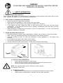
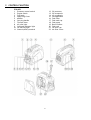
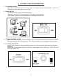
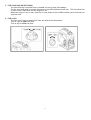
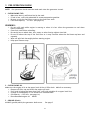
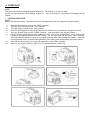
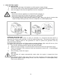
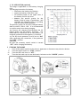
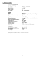
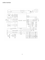
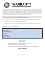
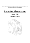
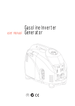
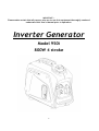
IMPORTANT ─
Please make certain that all persons who are to use this equipment thoroughly read and
understand this User’s Manual prior to operation.
Inverter Generator
Model 950i
800W 4 stroke
1
WARRANTY
This generator is backed by a comprehensive 12-month warranty. If you experience a mechanical fault that wasn’t
caused by user error, misuse or general wear and tear, please call 0800 045 100. You will be asked to explain what
the problem is, and if it is agreed that it is mechanical and covered by warranty, a claim number will be issued.
You can then take the generator to an authorised local repair agent. Quote your warranty claim number as well as
the serial number to the agent and they will contact us for permission to carry out the repairs. Spare parts will be
sent directly to the agent. They will invoice us directly with no costs to the owner.
Repairs not covered by warranty will need to be paid for by the owner. Spare parts specific to this generator are
available and may need to be purchased to complete the repair of the generator. These will be sent directly to the
repair agent, who will invoice the owner for the costs of parts and labour.
• Mechanical repairs carried out by someone other than an authorised repair agent will void this warranty.
• If this generator is purchased second hand, this warranty is void.
• Using parts other than ones specific to this generator, unless by prior arrangement, will void this warranty.
Please record your details in the space below:
GENERATOR SERIAL NUMBER:
PURCHASE DATE:
STORE PURCHASED FROM:
YOUR NAME:
YOUR ADDRESS:
YOUR PHONE NUMBER:
IMPORTANT
Please retain this warranty card, along with your purchase receipt.
Please DO NOT post this to The Warehouse Limited.
Should you have any questions regarding this generator please call the tollfree number:
0800 045 100
18
1.
2.
3.
4.
5.
6.
7.
8.
9.
10.
CONTENTS
SAFETY INFORMATION
CONTROL FUNCTIONS
PRE-OPERATION CHECKS
OPERATION
PERIODIC MAINTENANCE
TROUBLESHOOTING
STORAGE
SPECIFICATIONS
WIRING DIAGRAM
WARRANTY
3
3
4
8
9
12
15
15
16
15
18
WARNING
PLEASE READ AND UNDERSTAND THIS MANUAL COMPLETELY BEFORE
OPERATING THE MACHINE.
1.SAFETY INFORMATION
1 EXHAUST FUMES ARE POISONOUS
Never operate the engine in a closed area or it may cause unconsciousness and death within a short
time. Operate the engine in a well-ventilated OUTDOOR area.
2 FUEL IS HIGHLY FLAMMABLE AND POISONOUS
• Always turn off the engine when refuelling
• Never refuel while smoking or in the vicinity of an open flame.
• Take care not to spill any fuel on the engine or muffler when refuelling.
• If you swallow any fuel, inhale fuel vapor, or allow any to get in your eyes, see your doctor
immediately. If any fuel spills on your skin or clothing, immediately wash with soap and water
and change your clothes.
• When operating or transporting the machine, be sure it is kept upright. If it tilts, fuel may leak
from the carburettor or fuel tank.
3 ENGINE AND MUFFLER MAY BE HOT
• Place the machine in a place where pedestrians or children are not likely to touch the machine.
• DON’T place any flammable materials near the exhaust outlet during operation.
• Keep the machine at least 1m (3ft) from buildings or other equipment, or the engine may
overheat.
• Do not operate the engine with a dust cover in place.
• Lift and carry the generator only by its carrying handle.
• Put the machine on a flat, hard surface, to allow free ventilation and cooling.
4 ELECTRIC SHOCK PREVENTION
•
Never operate the engine in rain or snow.
•
Never touch the machine with wet hands or electrical shock will occur.
•
Be sure to always ground (earth) the generator.
NOTE: Use a ground (earth) lead of sufficient current capacity.
For example 1.5mm² wire
5 CONNECTION NOTES
•
NEVER connect the generator to a household switchboard or power outlet.
•
NEVER connect the generator in parallel with any other generator.
4
2 CONTROL FUNCTION
ITEM KEY
1
Economy control switch
2
Engine switch
3
Fuel tank
4
Spark Plug Cover
5
Muffler
6
Carrying handle
7
Throttle lever
8
AC pilot light
9
Overload indicator light
10 Oil warning light
11 Ground (earth) terminal
12
13
14
15
16
17
18
19
20
21
22
5
DC protector
DC receptacle
AC receptacle
not applicable
Fuel filter
Fuel tank cap
Fuel pump
Recoil Starter
Fuel cock
Oil filler cap
Air filter Cover
3 CONTROL FUNCTION DESCRIPTION:
1 OIL WARNING SYSTEM
When the oil level falls below the lower limit, the engine will stop automatically. Unless you
refill with oil, the engine will not start again.
2 ENGINE SWITCH
The engine switch controls the ignition system:
“ON”(run) - Ignition circuit is switched on. The engine can be started.
“OFF”(stop) - Ignition circuit is switched off. The engine will not run.
3 ECONOMY CONTROL SWITCH
When the economy control switch is turned “ON”, the economy control unit controls the engine
speed according to the connected load. The results are better fuel consumption and less noise.
4 DC CIRCUIT PROTECTOR
The DC circuit protector trips automatically when the load exceeds the generator rated output.
CAUTION:
Reduce the load to within specified generator rated output before restarting, if the DC circuit
protector should trip.
6
5 FUEL TANK CAP AIR VENT KNOB
The fuel tank cap is provided with a closable air vent to stop fuel leakage:
The air vent knob must be turned clockwise to the OPEN position before use. This will allow fuel
to flow to the carburettor and the engine to run.
When the engine is not in use, turn the air vent knob to the CLOSED position (anti-clockwise) to
stop fuel flow.
6 FUEL COCK
The fuel cock is used to supply fuel from the tank to the carburettor:
Turn to right to open fuel flow.
Turn to left to close fuel flow.
7
3 PRE-OPERATION CHECK
NOTE: Pre-operation checks must be made each time the generator is used.
1 CHECK ENGINE FUEL
• Make sure there is sufficient fuel in the tank.
• If fuel is low, refill with unleaded 91 octane automotive gasoline.
• Be sure to use the fuel filter screen on the fuel filter neck.
• Fuel tank capacity: 2.1 litre (see page 14)
WARNING:
•
•
•
•
•
•
Do not refill tank while engine is running or when it is hot. Allow the generator to cool down
before refuelling.
Close fuel cock before refuelling.
Be careful not to admit dust, dirt, water or other foreign objects into fuel.
Do not fill above the top of the fuel filter or it may overflow when the fuel heats up later and
expands.
Wipe off spilt fuel thoroughly before starting engine.
Keep open flames away.
2 CHECK ENGINE OIL
Make sure the engine oil is at the upper level of the oil filler hole. Add oil as necessary.
• Remove oil filler cap and check the engine oil level.
• If oil level is below the lower level line, refill with suitable oil to upper level line.
• Change oil immediately if it is found to be contaminated.
• Oil capacity: 0.35 litre (see page 14)
• Recommended engine oil: 10W30
3 GROUND (Earth)
ALWAYS ground (earth) the generator before use.
See page 3
8
4. OPERATION
NOTE:
The generator has been shipped without engine oil. Fill with oil or it will not start.
Do not tilt the generator when adding engine oil. This could result in overfilling and damage to the
engine
1 STARTING THE ENGINE
NOTE:
Before starting the engine, disconnect all electrical apparatus from the generator output sockets.
i.
ii.
iii.
iv.
v.
vi.
vii.
viii.
Open the fuel tank air vent to the “OPEN” position.
Turn the fuel cock lever to the “ON” position.
Turn the engine switch to the “ON” position
Press the priming bulb 6 times to get fuel to the carburettor (not necessary if engine is warm)
Turn the throttle lever to the “CHOKE” position. (not necessary if the engine is warm.)
Pull the starter handle slowly until resistance is felt. This is the “Compression” point. Return the
handle to its original position and pull swiftly. Do not fully pull out the rope. After starting,
allow the starter handle to return to its original position while still holding the handle. Grasp the
carrying handle firmly to prevent the generator from falling over when pulling the recoil starter.
Once started and running, move the throttle lever to the “RUN” position.
Warm up the engine without a load for a few minutes before connecting.
9
2 USING ELECTRIC POWER
1 AC APPLICATION
i.
Check the AC pilot lamp is lit brightly to confirm proper output voltage.
ii.
Turn off the switch of the electrical appliance before connecting to the generator.
iii.
Insert the plugs of the electrical appliance into the receptacle.
CAUTION:
• Be sure the electric appliance is turned off before plugging in.
• Be sure the total load is within the generator’s rated output.
• Be sure the outlet load current is within the rated current.
• The economy control switch must be turned to “OFF” when using electric devices that
require a large starting current, such as a compressor or a submergible pump.
OVERLOAD INDICATOR LIGHT
The overload indicator light comes on when an overload of a connected electrical device is
detected, the inverter unit overheats, or the AC output voltage rises. The electronic breaker will
then activate, stopping power to the generation in order to protect the generator and any
connected electric devices.
The output pilot light (green) will flicker and the overload indicator light (red) will turn on, then
the engine will stop running. If so please follow the following steps:
i.
Turn off any connected electric devices and stop the engine
ii.
Reduce the total wattage of connected electric devices to within the application range.
iii.
Check for blockages in the cooling air inlet and around the control unit. If any blockages
are found, remove.
iv.
After checking, restart the engine.
CAUTION:
The generator AC output automatically resets when the engine is stopped and then
restarted.
The overload indicator light may come on for a few seconds at first when using electric
devices that require a large starting current, such as a compressor or a submergible pump.
This is not a malfunction.
10
2 DC APPLICATION (optional)
This usage is applicable to 12V battery charging
only.
(a) Charging instruction for battery
• Disconnect the leads to the battery.
• Loosen the battery fluid filler caps.
• Fill distilled water to the upper limit, if
the battery fluid is low level.
• Measure the specific gravity for the
battery fluid by using a hydrometer, and
calculate the charging time in according
with the table shown alongside.
The specific gravity for the fully charged battery
shall be within 1.26 to 1.28. It is recommended
to confirm every hour during charging.
(b) Connect the charging lead between the DC
output socket and the battery terminals. The
leads shall be connected red to the positive (+)
terminal and black to the negative (-) terminal.
(c) The DC circuit protector is to be set to “ON”
after confirming the connection, if the protector
is in “OFF” position.
CAUTION:
Be sure the economy control switch is turned
“OFF” while charging the battery.
3 STOPPING THE ENGINE
i.
Turn off the power switch of the electric apparatus or disconnect any electric devices.
ii.
Turn the engine switch to “STOP” position.
iii.
Turn the fuel cock lever to “OFF”.
iv.
Turn the fuel tank cap air vent knob anti-clockwise to the “CLOSED” position.
11
5. PERIODIC MAINTENANCE
1…MAINTENANCE CHART
Regular maintenance is most important for the best performance and safe operation.
Item
Spark Plug
Engine oil
Oil Filter
Air Filter
Fuel Filter
Choke
Valve Clearance
Fuel Line
Exhaust Sytem
Carburettor
Cooling System
Starting System
Idle Speed
Fittings/Fasteners
Crankcase
Breather
Generator
Remarks
Check condition, adjust
gap and clean.
Replace if necessary.
Check level
Replace
Clean Filter
Clean. Replace if needed.
Clean Fuel cock filter.
Replace if needed.
Check operation
Check and adjust when
engine is cold
Check fuel hose for cracks
or damage. Replace if
needed.
Check for leakage.
Retighten or replace
gasket if needed.
Check muffler screen.
Clean/replace if needed.
Check choke operation.
Check fan for damage.
Check Recoil Starter
operation
Check and adjust engine
idle speed.
Check all fittings and
fasteners. Correct if
needed.
Check for cracks or
damage. Replace if
needed.
Check pilot light comes on
Pre-operation
check (daily)
Initial
1 month
or 20hr
Every
3 months
or 50hr
Every
6 months
Or 100hr
Every
12 months
or 300hr
●
●
●
●
●
●
●
●
●
●
●
●
●
●
●
●
●
●
12
2 ENGINE OIL REPLACEMENT
i.
Place the machine on a level surface and warm
up the engine for several minutes. Stop the
engine and turn the fuel cock knob to “OFF”.
ii.
Close the fuel tank cap air vent (counterclockwise).
iii.
Loosen the 4 screws and remove the side cover.
iv.
Remove the oil filler cap
v.
Place an oil pan under the engine. Tilt the
generator to drain the oil completely
vi.
Replace the generator on a level surface and
then add engine oil to the upper level.
vii.
Refit the oil filler cap
viii.
Re-install the side cover and replace the 4
screws.
• Recommended engine oil: 10W30 (see page
14)
•
•
•
CAUTION:
Be sure no foreign material enters the
crankcase.
Do not tilt the generator when adding
engine oil. This could result in overfilling
and damage to the engine
Clean the oil filter every 100 hours of
operation.
3 AIR FILTER
Maintaining an air cleaner in proper condition is very
important. Dirt induced through improperly installed,
improperly serviced, or inadequate elements damages
and wears out engines. Always keep the element clean.
i.
Remove the side cover.
ii.
Remove the filter cover and foam element.
iii.
Wash the foam element in solvent and dry.
iv.
Oil the element and squeeze out excess oil. The
element should be wet but not dripping.
v.
Insert the foam element back into the air filter
and replace the filter cover.
vi.
Install the side cover.
CAUTION:
NEVER run the engine without the filter
element - excessive piston and/or cylinder
wear will result.
13
4 CLEANING AND ADJUSTING SPARK PLUG
i.
Remove the top cover.
ii.
Carefully remove the sparkplug with the tube
spanner provided.
iii.
Check for discoloration and remove and carbon
deposits.
iv.
Check the spark plug type and gap.
v.
Re-install the spark plug. Do not overtighten.
vi.
Re-install the top cover.
5 FUEL TANK FILTER
i.
Remove the fuel tank cap and filter.
ii.
Clean the filter with solvent.
(If damaged,
replace the filter.)
iii.
Wipe the filter down and refit into the neck of
the tank.
WARNING
• Be sure the tank
tightened securely.
cap
is
always
6)MUFFLER SCREEN
WARNING
• The engine and muffler will be very hot
after the engine has been run. Allow to
cool down fully before working on the
muffler.
• Avoid touching the engine and muffler
while they are still hot with any part of
your body or clothing during inspection
or repair.
i.
ii.
iii.
iv.
v.
vi.
Remove the 4 screws and the end cover.
Remove the muffler screen.
Use a flathead screw driver to pry the spark
arrester out from the muffler.
Remove the carbon deposits on the muffler
screen and spark arrester using a wire brush.
Re-install the muffler screen.
Re-install the end cover and 4 screws.
14
6.
.TROUBLE SHOOTING
1…Engine won’t start
1. Fuel systems - no fuel supplied to combustion chamber.
• No fuel in tank - supply fuel.
• Fuel in tank - fuel tank cap air vent knob to “OPEN”, fuel cock knob to “ON”.
• Clogged fuel line - clean fuel line.
• Clogged carburettor - clean carburettor.
2.Engine oil system insufficient
• Oil level is low - add engine oil.
3. Electrical systems - poor spark
• Spark plug dirty with carbon or wet - remove carbon or wipe spark plug dry.
• Faulty ignition system - consult dealer.
4. Compression insufficient
• Worn out piston and cylinder - consult dealer.
2 Generator won’t produce power
Safety device (AC) to “OFF” - Stop the engine, then restart.
Safety device (DC) to “OFF” - Press to reset the DC protector
7. STORAGE
Long term storage of your machine will require some preventive procedures to guard against
deterioration.
1 DRAIN THE FUEL
i.
Remove the fuel tank cap, drain the fuel from the fuel tank
ii.
Remove the cover, drain fuel from the carburettor by loosening the drain screw.
2 ENGINE
i.
Remove the spark plug, pour in about one tablespoon of SAE 10W30 or 20W40 motor oil into the
spark plug hole and reinstall the spark plug.
ii.
Use the recoil starter to turn the engine over several times (with ignition off).
iii.
Pull the recoil starter until you feel compression, then stop pulling.
iv.
Clean exterior of the generator and apply a rust inhibitor.
v.
Store the generator in a dry, well-ventilated place, with a cover placed over it.
vi.
The generator must remain in a vertical position.
15
8. SPECIFICATION
MODEL 950i GENERATOR
Inverter Technology
AC Voltage:Max. Output:Rated Output:Power Factor:DC Output:-
50Hz 100, 230V, 240V
0.80 kVA
0.70 kVA
1.0
12V / 3.0A (Option)
ENGINE
Model:Type:Bore × Stroke (mm × mm):Displacement:Max. Output:Fuel:Fuel Tank Capacity:Rated Continuous Operation:Lubricating Oil:Lubricating Oil Capacity:Starting System:Ignition system:Spark Plug:-
XY139F-6
Air-cooled, 4 cycle, OHV, Gasoline Engine
39×33.5
40 cc
1.0KW / 5500rpm
Unleaded 91 Octane Automobile Gasoline
2.1 liters
4.5 hr
SAE 10W30
0.35 liter
Recoil Starter
C.D.I.
CMR6A (TORCH) or CMR6H (NGK)
DIMENSION
Net dimension (L×W×H):Overall dimension (L×W×H):Net Weight:Dry Weight:-
395×209×355
425×230×380
8.5 Kg
9.5Kg
Specifications subject to change without prior notice.
16
WIRING DIAGRAM
17
WARRANTY
This generator is backed by a comprehensive 12-month warranty. If you experience a mechanical fault that wasn’t
caused by user error, misuse or general wear and tear, please call 0800 045 100. You will be asked to explain what
the problem is, and if it is agreed that it is mechanical and covered by warranty, a claim number will be issued.
You can then take the generator to an authorised local repair agent. Quote your warranty claim number as well as
the serial number to the agent and they will contact us for permission to carry out the repairs. Spare parts will be
sent directly to the agent. They will invoice us directly with no costs to the owner.
Repairs not covered by warranty will need to be paid for by the owner. Spare parts specific to this generator are
available and may need to be purchased to complete the repair of the generator. These will be sent directly to the
repair agent, who will invoice the owner for the costs of parts and labour.
• Mechanical repairs carried out by someone other than an authorised repair agent will void this warranty.
• If this generator is purchased second hand, this warranty is void.
• Using parts other than ones specific to this generator, unless by prior arrangement, will void this warranty.
Please record your details in the space below:
GENERATOR SERIAL NUMBER:
PURCHASE DATE:
STORE PURCHASED FROM:
YOUR NAME:
YOUR ADDRESS:
YOUR PHONE NUMBER:
IMPORTANT
Please retain this warranty card, along with your purchase receipt.
Please DO NOT post this to The Warehouse Limited.
Should you have any questions regarding this generator please call the tollfree number:
0800 045 100
18