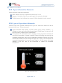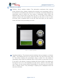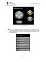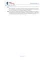
1
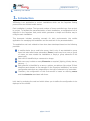
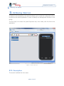
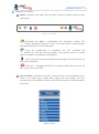
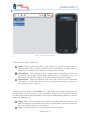
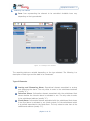
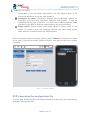
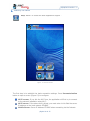
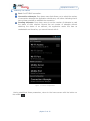
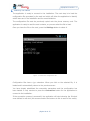
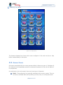
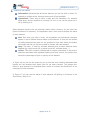
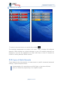
JGCBusing
User Manual v1.1
Agosto 2012
25/08/2012 versión 1.1
JGCBusing. User Manual
Table of Contents
1.
Introduction ................................................................................................... 3
2.
JGCBusing. Web tool....................................................................................... 4
2.1.
Description .............................................................................................. 4
2.2.
Creating a configuration from scratch ........................................................ 7
2.3.
Generating the configuration file .............................................................. 13
2.4.
Access to stored configurations ................................................................ 14
3.
JGCBusing. Mobile Application ........................................................................ 15
3.1.
First Steps .............................................................................................. 15
3.2.
Screen Zones .......................................................................................... 19
3.3.
Types of Static Elements.......................................................................... 21
3.4.
Types Informative Elements ..................................................................... 22
3.5.
Types of Operational Elements ................................................................. 22
página 2 de 25
25/08/2012 versión 1.1
JGCBusing. User Manual
1. Introduction
JGCBusing is an application to control installations which use the Ingenium Busing
protocol from an Android mobile device.
Each installation is unique. The type and number of items controlled vary from project
to project. To facilitate the parameterization of each installation, a configuration tool is
deployed in the Ingenium web portal which generates a simple and intuitive way to
configure each installation.
This document includes operating manuals for both environments: the mobile
application for managing the installation and the web tool for its parameterization.
The application and tools related to them have been developed based on the following
premises:
A mobile device has a small size screen, that is why it was decided to group
items into sets called home automation Zones (a zone may be a room, a group
of rooms, an area outside the installation or simply a group elements of the
same type).
Each zone is identified by a name and an image.
Each zone may include as many Elements as required (lighting, blinds, alarms,
sensors, …)
Each element is identified by a name, a picture, an address (the unique ID that
identifies each element to be managed in the Ingenium installation) and some
configuration data that vary depending on the type of element to be controlled.
Therefore, the configuration of this environment is based on defining zones
and the elements associated with them.
Let’s start by analyzing the web tool which allows you to define the configuration to be
deployed on the mobile.
página 3 de 25
25/08/2012 versión 1.1
JGCBusing. User Manual
2. JGCBusing. Web tool
As stated in the introduction, this web tool allows you to create the configuration file to
be used on the mobile application in order to identify and manage each element in the
facility.
The first step is to access the portal Ingenium and, once inside, click the link to the
application.
Figure 1. View of the tool
2.1. Description
The screen is divided into four areas:
página 4 de 25
25/08/2012 versión 1.1
JGCBusing. User Manual
Menu: Located on the upper left, the menu (Figure 2) allows access to basic
commands:
Figure 2. Tool menu
Command to load a configuration file previously created. The
configuration generated is saved to a file. If you later wish to make changes,
this option allows you to load them again.
Once the configuration is completed, this icon generates the
configuration file. This file must be copied to the memory card of a mobile
phone to update the application configuration.
Use if you wish to erase everything and start again, this icon brings you
back to the beginning.
Help icon. It displays the help file. It shows a small help menu for the
tool. It has a link to this PDF.
List of Zones: Located on the left, it shows the list of zones defined so far.
There is an initial zone, named Main, which can’t be erased. This zone
corresponds to the application home screen JGCBusing and it includes access to
each zone.
página 5 de 25
25/08/2012 versión 1.1
JGCBusing. User Manual
Figure 3. List of Zones
Zone Contents: Located on the right. It shows the elements that have been
added to each zone. By selecting a specific zone in the zone list, its contents
are displayed. Figure 4 shows an example of contents of the Principal zone
(with access to each zone) and Figure 5 the content of a particular zone.
Figure 4. Principal Zone Content
Figure 5. Contents of a zone
The name of the zone is always displayed at the top of the screen and at the
bottom, the Create icon. This icon allows you to create a new zone if Principal
zone has been selected, or a new element if any other zone has been selected.
página 6 de 25
25/08/2012 versión 1.1
JGCBusing. User Manual
Central Block. Each time you create or modify a zone or an element, this
block shows the associated data. Depending on the object you are adding
(zone or element) the data required vary (Figure 6 to create a new zone; Figure
7 to create a new element).
Figure 6. Create a new zone
Figure 7. Create an element
Both displays share the same icons:
Icon to create or modify a zone or an element
Icon to remove a zone or an element
The Icons are placed on the screen. The Up icon moves the selected icon
up on the screen.
The icons are placed on the screen. The Down icon moves the selected
icon down on the screen.
The following sections will show you how to create, modify, delete and manage
zones and elements.
2.2. Creating a configuration from scratch
Knowing the interface of the tool; we will show step by step how to create a
configuration for the application JGCBusing.
página 7 de 25
25/08/2012 versión 1.1
JGCBusing. User Manual
As shown in Figure 1, when you start the application, the only zone available is the
Main (where the icons that give access to all other Zones will be placed), therefore the
first step is to create the Zones in which you wish to separate the various elements.
Clicking the icon "Create", you access the form to create a new zone (Figure 7). As
you can see, each zone is identified by two kinds of data:
Name: Text that identifies the zone. You must take into account the fact that
this text is displayed below the selected icon, so if the name is too long it will
not be properly displayed.
Icon: There is a list of icons to represent the different areas or zones to be
defined. Select the most appropriate (Figure 7).
Figure 7. Creating a new zone
Once you have completed the name and selected an icon, press the Record button to
create the new zone (Figure 8). To illustrate this, we have created a zone called
"Exterior" to include all the automated elements located outdoors.
página 8 de 25
25/08/2012 versión 1.1
JGCBusing. User Manual
Figure 8. Exterior zone created
You may create all the zones you need following these steps. If you want to change
the position of an icon (order) or to modify the data in a zone (the name or icon), click
on the icon of the zone to be modified (on the left of the screen) and it will display the
data so that it can be modified.
Repeating these steps you will create each of the zones that will appear on the zone
list on the left.
The next step is to include in each zone the elements to control. To access the zone of
each screen, click the button on the same Zones list (Figure 9).
The upper right of the tool displays the name of the zone that is being edited (in our
example, "Exterior").
página 9 de 25
25/08/2012 versión 1.1
JGCBusing. User Manual
Figure 9. Exterior zone contents
There are three types of elements:
Static: These are elements which, when clicked on, execute an action but are
not associated with a specific element and no information on their status is
displayed; for example the execution of a scene from a screen.
Informative: Those elements which display status information but are not
interactive (for example a flood sensor that shows if it is enabled or not, or a
light sensor showing the amount of lux that is detected at any moment).
Operational: These are elements that show their status and are interactive
(for example, a blind that the user can pull up/down knowing its state or an
alarm that can arm or disarm).
To add new items, click on the Create icon. In the same way as when creating a zone,
in the central area of the screen a form is displayed (Figure 10). In this case the form
has fixed and variable data depending on the type of element being defined. Common
data to all elements are:
Name: Name to be displayed on the button associated with that element. As it
was the case with zone names, the name of the element is displayed inside the
icon so its length should not be excessive.
Type: This field defines the type of element to be controlled.
página 10 de 25
25/08/2012 versión 1.1
JGCBusing. User Manual
Icon: Icon representing the element to be controlled. Available icons vary
depending on the type selected.
Figure 10. Creating a new element
The remaining data are variable depending on the type selected. The following is a
description of each type and the data to be introduced.
Type of Elements
Arming and Disarming Alarm: Operational element associated to arming
and disarming the alarm. The only value to enter is the switchboard address
(usually “0”).
Intrusion Alarm: Informative element associated with the switchboard that
shows whether the intrusion alarm is activated or not. The only value to enter
is the switchboard address (usually “0”).
Flood Alarm: Informative element associated with the switchboard that shows
if the flood alarm is activated or not (check output 6 of the switchboard which
is by default associated to the flood alarm. The only value to enter here is the
switchboard address (usually “0”).
página 11 de 25
25/08/2012 versión 1.1
JGCBusing. User Manual
Fire or Gas Alarm: Informative element associated with the switchboard that
shows whether the gas or fire alarm is activated or not (check output 5 of the
switchboard which is by default associated with the flood alarm. The only value
to enter is the switchboard address (usually “0”).
Intrusion Call Control: Operational element to enable or disable calls from
the switchboard when an intruder alarm is activated. The only value to enter
here is the switchboard address (usually “37”).
Flood Call Control: Operational element to enable or disable calls from the
switchboard when a flood warning is activated. The only value to enter here is
the switchboard address (usually “37”).
Gas of Fire Call Control: Operational element to enable or disable calls from
the switchboard when a fire or a gas alarm is activated. The only value to enter
here is the switchboard address (usually “37”).
Power Outlets: Operational element acting on any power outlets (sockets,
motorized gates, pumps, irrigation systems ...). You must enter the computer
address data that controls that outlet and its output number.
Lighting: Operational element acting on any line of lighting. You must enter
the computer address data that controls that outlet and its output number.
Regulated lighting: Operational element acting on any line of lighting in
which the intensity can be regulated. You must enter the computer address
data that controls the outlet and its output number.
Blind: Operational element acting on any blind, awning, window shades ...
which is motorized. You must enter the computer address data that controls
the outlet and its output number (1, 3 or 5) as well as the type of equipment
(computer with 6 inputs and 6 outputs, computer with 4 inputs and 4 outputs
or computer with 2 inputs and 2 outputs).
Sreen: Operational element to access programmed scenes on a screen. You
must enter the computer address and then the scenes you wish to manage. To
enter the scenes, click on the button
. This opens a window in which to
enter the name and scene number (number assigned when you programmed
the screen). You can add as many scenes as desired. To delete a scene, click
on the button
associated with it.
Intrusion Probe: Informative element associated with an intrusion sensor. It
shows if it is active or not. The only value to enter is the probe address.
Flooding Probe: Informative element associated with a flood sensor. It shows
if it is active or not. The only value to enter is the probe address.
Gas or Fire Probe: Informative element associated with a gas sensor. It
shows if it is active or not. The only value to enter is the probe address.
Twilight Sensor: Informative element showing the amount of lux detected by
the sensor if you are in threshold mode and the percentage of light if you are in
linear mode. The only value to enter is the sensor address.
Thermostat: Operational element acting on an independent thermostat or on
one included in a screen. With this element you can check the current
página 12 de 25
25/08/2012 versión 1.1
JGCBusing. User Manual
temperature or set the desired temperature. The only value to enter is the
thermostat address or the screen that includes it.
Command or scene: Operational element fully configurable suitable for
integrators who know the equipment operation and protocol. It may be
associated with any type of element. You must enter the device address, data1
and data2 (basic data to generate a data packet in the protocol Busing).
Empty space: Special element that simply leaves an empty space on the
screen. It is used to order the remaining elements and leave empty spaces
where desired. No need to enter any additional data.
Once the data have been introduced, with the button "Record", the element is added
to the zone. If you wish to modify, delete or reorder, click again on the icon to access
your data.
Figure 11. Element created
2.3. Generating the configuration file
The last step, having defined zones and the elements of each zone, is to generate the
application configuration file.
página 13 de 25
25/08/2012 versión 1.1
JGCBusing. User Manual
The button
generates a new configuration file. This file is copied onto the phone
memory card. The next steps are explained in detail below in the application manual
JGCBusing.
2.4. Access to stored configurations
As you create new settings, these can be saved and later re-accessed to make any
changes required. Simply save the file generated as explained above and when you
need to go back to them the button
allows you to upload the file again.
página 14 de 25
25/08/2012 versión 1.1
JGCBusing. User Manual
3. JGCBusing. Mobile Application
As noted in the introduction, the application JGCBusing allows you to control a domotic
installation which uses Busing protocol from anywhere in the world via the Internet.
The basic characteristics of this application are:
Multiplatform. It works with any mobile device with an Android operating
system (version 2.3 or higher)
Multi-language. The current version supports English and Spanish languages
(the choice of either language is done automatically, based on the language
selected for the phone).
Multi-Installation: Simply by selecting the appropriate configuration file, the
application can control different installations.
Wi-Fi and mobile network. The application has been designed to
significantly reduce traffic between the mobile and the installation, increasing
its speed of response and minimizing consumption of data transfer (for mobile
networks).
Parametrizable. The application has a configuration screen to set the basic
parameters of operation.
3.1. First Steps
Each time the application starts, it tries to connect to the computer ETHBUS (Ingenium
Web server to which the application connects). The first time you start the application,
it does not have the information needed to connect with the installation, so after
several failed attempts, a configuration screen will be displayed (Figure 12).
In this screen there are the following buttons:
Configuration. Button to load a new configuration file generated with the
web tool as explained before in this manual.
Parameterization. Button to access the basic connection settings of the
application.
Connection. Button to connect to the installation.
página 15 de 25
25/08/2012 versión 1.1
JGCBusing. User Manual
Help. Button to access the basic application support .
Figure 12. Access Screen
The first step is to establish the basic connection settings. Press Parameterization
button to open a screen (Figure 13) to configure:
Wi-Fi access: If you tick the Wi-Fi box, the application will first try to connect
to the network installation using Wi-Fi.
Wi-Fi server: If the above box is ticked, you must enter in this field the server
IP address on the local network ETHBUS.
Mobile Server: Server IP Address ETHBUS when connecting via the Internet.
página 16 de 25
25/08/2012 versión 1.1
JGCBusing. User Manual
Port: Port ETHBUS connection.
Connection attempts: Drop down menu that allows you to select the number
of connection attempts the application should carry out before indicating that it
has not been possible to establish the connection.
Reading attempts: Drop down menu to set the number of attempts to read
the status of each element. Beyond the set number of attempts without
obtaining the status of an element, the application marks this item as
unattainable and therefore, you cannot interact with it.
Figure 13. Screen configuration
Having established these parameters, return to the home screen with the button on
the mobile
página 17 de 25
25/08/2012 versión 1.1
JGCBusing. User Manual
The application is ready to connect to the installation. The next step is to load the
configuration file generated by the web tool which will allow the application to identify
which items are in the installation and its zone distribution.
The configuration file must be previously copied onto the phone memory card. The
application is ready to read the card contents, so you can select the file to load.
Once you have the file on the card, press the Settings button to select it.
Figure 14. Select the configuration file
Configuration files have a jgs. extension. When you click on the selected file, it is
loaded and it automatically returns to the previous screen.
You have already established the connection parameters and the configuration has
been loaded. It only remains to press the Connection button for the application to
connect to the installation.
If the connection process is successful, the application will start showing the Principal
zone defined in web tool (this screen contains the buttons to link to each of the zones).
página 18 de 25
25/08/2012 versión 1.1
JGCBusing. User Manual
Figure 15. Main Screen
The buttons displayed are those which were configured in the web tool plus a help
button located always in last place.
3.2. Screen Zones
All screens associated with the zones operate similarly. When you open it, it displays all
the elements and immediately sends the commands necessary to find out the status of
its components.
As mentioned in the tool manual, there are three types of elements:
Static: These elements are generally associated with screens scenes. They do
not have a verifiable state and by clicking on them, they run configured scene.
página 19 de 25
25/08/2012 versión 1.1
JGCBusing. User Manual
Informative: Elements that do have a state but you can not click on them. For
example, a twilight sensor showing the amount of light available.
Operational: Those who do have a state and are interactive. For example
street lamp, which in addition to knowing if it is on or not, can be turned on or
off by clicking on it.
Static elements therefore do not required a status check. However, for the other two
types of buttons it is necessary. The application uses a color code to display the status
of each element:
Red: Each time you enter a zone, all information and operational elements
appear in red to indicate that its status is still unknown. If once the set number
of reading attempts has gone it is not possible to know their status, the button
will remain red and you will not be able to interact with that element.
Gray: This color is used for all static elements and all other elements when
disabled (eg a light turned off, a socket turned off, a shutter down, ...)
Yellow: This color is used to indicate that an output is activated. In the case of
elements associated with regulated lighting and blind control, the yellow color
shows the percentage of light or opening of the element.
In Figure 16 you can see the screen as you go into that zone. Buttons associated with
lighting are red because their status has not yet been checked. The garage door
button is gray because it is associated with a scene of a screen and therefore it is not
necessary to check its status.
In Figure 17 you can see the status of each element. All lighting is off except in the
Store Room, which is on.
página 20 de 25
25/08/2012 versión 1.1
JGCBusing. User Manual
Figure 16
Figure 17
To return to the zone screen you use the phone button
.
The operating arrangements are similar in all zones. First, it displays all configured
elements. Static elements are directly displayed in gray. All remaining elements are
displayed in red until the application can check their state or when it exceeds the
number of reading attempts without success.
3.3. Types of Static Elements
These elements allow the execution of screen scenes or specific commands (advanced
settings). Typical examples include:
Implementation of a scene that turns off all lights, or lets down all blinds.
Scene to initiate the programming of an irrigation system.
...
página 21 de 25
25/08/2012 versión 1.1
JGCBusing. User Manual
3.4. Types Informative Elements
There are several informative elements:
Alarm buttons report if an alarm has been set off or not.
Sensors: (intrusion, flood, fire or gas) report if a sensor is activated.
Twilight sensor that indicates the amount of light detected at each moment.
3.5. Types of Operational Elements
These are the most complete elements since you can check their status as well as
intereract with them. There are several:
Those associated with lighting or power points (plugs, pumps, cameras, ...).
Clicking on these will reverse the current state (if they were on they turn off
and vice versa), changing color automatically.
Thermostats: The thermostat button displays current temperature detected. If
you click on the button it opens a window (Picture 18) where you can see the
requested temperature and current temperature detected. Placing your finger
on the thermometer bar and moving the finger up or down, you can change the
requested temperature. As soon as your finger is off the screen, the value
selected is set and sent to the thermostat to update the requested
temperature.
Figure 18. Thermostat control
página 22 de 25
25/08/2012 versión 1.1
JGCBusing. User Manual
Shutters, blinds, window shades: The automation equipment that controls
these elements has a display indicating the opening as a percentage (100% if
the element is completely open and 0% if it is closed). The button displays the
percentage using a yellow bar (the button is completely yellow when the
detected rate is 100% and is gray when it's 0%). If you click on the button, it
opens a window with three objects: two buttons on the right to raise or lower
the blind, and a complete blind on the left. With the finger you can raise or
lower the blind to the percentage you wish.
Figure 19. Blind regulation
Regulated lighting: This element controls lighting lines connected to a dimmer
switch. This element will be at 0% when the light is off and 100% when fully
lit. The button displays the percentage using a yellow bar (the button is
completely yellow when the detected rate is 100% and it is gray when it's 0%).
If you click on the button, it opens a window with three objects: two buttons on
the right to turn on or off completely the light and a control on the left. With
your finger you can set the desired percentage in the same way you would do
with a volume control. The percentage of lighting set is displayed under the
control at all times.
página 23 de 25
25/08/2012 versión 1.1
JGCBusing. User Manual
Figure 20. Regulation Lighting
Scenes: This element allows access to the scenes in an automation screen.
Clicking on it, it opens a window with one button for each of the scenes defined
in the configuration file. Just click on any of them for the application to send
the executable order.
Figure 21. Screen scenes
página 24 de 25
25/08/2012 versión 1.1
JGCBusing. User Manual
Arming and disarming: Special element that allows you to arm and disarm an
alarm installation. It is yellow if the alarm system is armed and ready, and gray
if it is disarmed. If you click on it, it runs the opposite action to its current state
(it will arm the alarm if it is disarmed or disarm it if armed).
Call Control: This element can activate or deactivate the phone calls made by
the switchboard when an alarm is detected. If the button is gray, it means that
these calls will not be made and yellow indicates the opposite. If you click on it,
it runs the opposite action to the current states.
página 25 de 25