1
PRODUCT MANUAL
KLIC-DI
Interface KNX - Variable Refrigerant
Volume
ZN1CL-KLIC-DI
Program version: 1.3
Manual edition: a
INDEX
1. Introduction .............................................................................................................................................. 3
1.1.
KLIC-DI ............................................................................................................................................ 3
1.2.
Installation ...................................................................................................................................... 4
2. Configuration............................................................................................................................................. 7
2.1.
Basic control .................................................................................................................................... 7
2.2.
Advanced functionalities ................................................................................................................. 8
2.3.
Control using IR remote................................................................................................................. 11
3. ETS Parameterization ............................................................................................................................... 12
3.1.
Default configuration .................................................................................................................... 12
3.2.
General window ............................................................................................................................ 13
3.2.1.
Scenes ................................................................................................................................... 14
3.2.2.
Temperature limitation.......................................................................................................... 15
3.2.3.
Auto OFF ............................................................................................................................... 16
3.2.4.
Errors management ............................................................................................................... 16
3.2.5.
Start-up configuration............................................................................................................ 17
3.2.6.
Type of control ...................................................................................................................... 18
3.2.7.
Swing..................................................................................................................................... 19
3.3.
Mode window ............................................................................................................................... 21
3.4.
Fan window ................................................................................................................................... 22
Annex I. Communication objects ................................................................................................................... 24
Annex II. Correspondence Error Codes of the A/C Units ................................................................................ 26
ZENNiO AVANCE Y TECNOLOGÍA
vwww.zennio.com
2
1. INTRODUCTION
1.1.
KLIC-DI
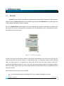
KLIC-DI is an interface that allows a bidirectional communication between a KNX domotic
system and the commercial series of air-conditioning units and the industrial air-conditioning units
of the Variable Refrigerant Volume systems.
Due to its bidirectional communication, the air conditioning unit can be controlled in the same way
as using an IR remote control and the real status if the air-conditioning unit is checked and sent to
the KNX bus for its monitoring.
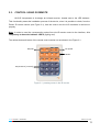
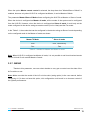
Figure 1.1. KLLIC-DI interface
Is case of using a wired remote control in the same communication bus of the unit, KLIC-DI will
communicate with this remote control in a bidirectional way, one acting as master control and the
other, as slave control. It is important to verify that KLIC-DI and the wires remote control are
configured with different types of control. This way, the control acting as slave will update its status
when the master orders it and will communicate its status changes when they are modified from the
own slave control.
KLIC-DI has several features, among which:
Controls bidirectionally the industrial A/C units (Variable Refrigerant Volume).
ZENNiO AVANCE Y TECNOLOGÍA
vwww.zennio.com
3
Control over all the air-conditioning unit functionality. Error management handles the own
A/C unit error codes as well as any communication errors that may arise.
LED indicator that allows monitoring the bidirectional traffic flow.
1.2. INSTALLATION
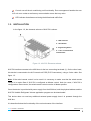
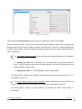
In the figure 1.2, the elements scheme of KLIC-DI is shown.
1.- KNX connector
2.- LED indicator
3.- Programming button
4.- 2-wire communication
terminal block
Figure 1.2. KLIC-DI. Elements scheme
KLIC-DI interface connects to the KNX bus via the bus connecting terminals (1). On the other hand,
this device is connected to the A/C internal unit PCB (P1/P2 connectors), using a 2-wire cable. See
figure 1.3.
Note: If the wired remote control is also used it is necessary to make sure that the wired remote
control is in mode Slave if KLIC-DI is configured as Master control. And vice versa, if KLIC-DI is
configured as Slave control, the wired remote control must be in Master position.
Once the device is provided with power supply from the KNX bus, both the physical address and the
KLIC-DI Variable Refrigerant Volume application program can be downloaded.
This device does not need any additional external power supply since it is powered through the
KNX bus.
It is described below the functionality of the main elements of the interface:
ZENNiO AVANCE Y TECNOLOGÍA
vwww.zennio.com
4
Programming button (3): a short press on this button sets the device in programming
mode, and the associated LED (2) lights red. If this button is held while plugging the device
into de KNX bus, KLIC-DI goes into secure mode.
LED indicator (2): luminous signal that indicates the working state of KLIC-DI. Besides
lighting red when the device is in programming mode, this LED may also light blue and green,
thus indicating the status of the bidirectional communication between KNX and the A/C unit,
resulting very useful in the installation process. Next, the meaning of every LED color:
Fixed red: KLIC-DI is in programming mode.
Blinking red: KLIC-DI is in secure mode (the LED blinks red every 0.5 seconds).
Fixed green: failure in the KLIC-DI power supply (this happens when KLIC-DI is not
connected to the AC unit and/or when the AC unit is not connected to the power supply
line).
Blinking green: communication data from AC unit to KLIC-DI.
Blinking blue: communication data from KLIC-DI to AC unit.
Communication cable: 2-wire cable, connected on one hand to KLIC-DI (through the
provided terminal block (4)) and, on the other hand, direct to P1/P2 connectors that can be
found at the PCB of the internal unit, or in the wired remote control.
ZENNiO AVANCE Y TECNOLOGÍA
vwww.zennio.com
5
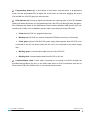
Figure 1.3. Connecting KLIC-DI to P1/P2 bus
Figure 1.4. Connecting KLIC-DI to bus P1/P2 with wired remote control
Diagrams legend
A
B
C
P1-P2
1-2
*
ZENNiO AVANCE Y TECNOLOGÍA
KLIC-DI
Wired remote control
A/C unit
Connection base to A/C unit
Zennio connection terminal block
The wired remote control must operate in the
opposite mode to KLIC-DI
vwww.zennio.com
6
To obtain more detailed information about the technical features of KLIC-DI, as well as security and
installation information, please read the interface Datasheet, included in the original package of the
device and also available at http://www.zennio.com.
It is also recommended to consult the KLIC-DI Installation Note, also available in the same web
site.
2. CONFIGURATION
2.1. BASIC CONTROL
With KLIC-DI, the air-conditioning unit can be monitored and controlled the same way it is
done with the infrared remote control provided with it.
By means of the KNX bus, the following basic functionalities of the air conditioning unit can be
controlled:
ON/OFF of the air-conditioning unit
Setpoint Temperature. Between 16 and 32ºC.
Operating mode: Heat, Cool, Fan and Dry.
Fan speed: 2 or 3 speed levels configuration. (Check out the available levels in the A/C
unit).
Swing (if available): swing or fixed position (5 different positions).
These functionalities have associated a machine status, which is periodically sent to KLIC-DI When
KLIC-DI receives a status different from the previous one from the machine, it updates the status of
the corresponding parameter in the KNX bus.
ZENNiO AVANCE Y TECNOLOGÍA
vwww.zennio.com
7
2.2. ADVANCED FUNCTIONALITIES
Besides the basic control over the air-conditioning system, KLIC-DI offers other advanced
functionalities that give an added value with regard to the remote control.
Scenes configuration: allows establishing a specific parameters combination in order to
generate a determined climate ambient in the room. KLIC-DI allows configuring up to 4
different scenes.
Auto OFF: allows an automatic and temporary switch off of the machine (after an
established delay, if parameterized) if a status change in the communication object associated
to it takes place. An example of this functionality could be the use of a window sensor,
associated to the auto switch off, which allows switching off the machine if the window is
opened.
Temperature limitation: air conditioning systems are limited in temperature to the range
16-32ºC. This KLIC functionality allows configuring custom temperature ranges for the modes
Heat and Cool by means of ETS, provided that these values keep the range. In case of
receiving from the KNX bus a temperature command with a value out of the configured limits,
the temperature value sent to the machine will be the corresponding limit value.
Indoor temperature and Reference temperature: the Variable Refrigerant Volume units
have several temperature sensors for measuring the temperature in different internal points.
The Indoor temperature is the measured internal value and it is used together with the
Reference temperature for controlling the modes Auto-Cool and Auto-Heat of the A/C
machine.
The Reference temperature is the real temperature i the room to acclimatize. It is necessary
to communicate this parameter to the machine by means of the corresponding communication
object and it is highly recommended to link this communication object with a temperature
sensor (installed in the room), which periodically updates the temperature value.
The modes Auto-Heat and Auto-Cool can be controlled in three different ways by the A/C
units:
1. The machine receives the Reference Temperature and, according to a pre-configured
hysteresis, it establishes the corresponding auto mode.
ZENNiO AVANCE Y TECNOLOGÍA
vwww.zennio.com
8
2. The machine uses he Indoor Temperature and, according to a pre-configured
hysteresis, it establishes the corresponding auto mode.
3. The machine establishes the auto mode according to the average value of the
Reference Temperature and the Indoor Temperature.
The temperature value used by the machine for switching between the modes Auto-Cool and
Auto-Heat depends on the configuration established in the A/C unit installation. This value, in
any of the previous cases, is compared to the setpoint temperature in such way that if the
setpoint temperature is higher, the Auto-Heat mode is established and if the setpoint
temperature is lower than this value, the Auto-Cool is established.
Take into account: It is highly recommended to link the Reference Temperature to a
temperature sensor that periodically monitors the real temperature in the room, because it is
possible not to know the switching way pre-configured in the machine and this fact can lead to
a wrong functioning of the Auto mode. The Reference Temperature has a default value of
25ºC.
Errors management: this functionality allows sending messages to the KNX bus
informing about errors. Errors management handles the A/C unit error codes as well as any
communication errors that may arise.
Besides informing about the apparition of possible errors it can be also configured the sending
of the error type. In case of internal errors, the numerical code associated to the error type is
shown in Table 2.1.
Error Number
1
2
3
4
Type of Internal Error
Problems with the data reception (speed,
parity, etc.)
Communication waiting time exceeded (Time
Out)
Incorrect checksum
Incorrect response from the machine
Table 2.1. Type of Internal Error
Regarding the numerical code associated to the type of external errors, please look up the
manual of the installed air-conditioning system or the Annex II. Correspondence Error Codes
of the A/C Units.
ZENNiO AVANCE Y TECNOLOGÍA
vwww.zennio.com
9
Initial configuration: this functionality allows establishing an initial value for the A/C unit
statuses after installing the system or after recovering from a power failure. The statuses that
may be configured are: ON/OFF, temperature, mode, fan and swing of the machine.
The initial values can be sent to the KNX bus.
Type of control: It is important to take into account the type of control (Master or Slave),
with which the KLIC-DI is going to be configured.
The Master remote control in the installation is in charge of the communication with the
machine and it will retransmit the instructions and status between the machine and the slave
remote control, in case of having one. However, all the functionalities of the machine can be
set from both remote controls.
This functionality allows including in the installation both the KLIC-DI and the A/C unit wired
remote control and choosing the desired master/slave configuration whenever the KLIC-DI
and the wired control are not configured with the same type of control.
In case of having both controls configured as Masters, the screen of the A/C unit control will
show the error "88" and the error "U5" will be sent to the bus.
Note: When switching the type of control of the A/C unit wired control between Master and Slave it
is necessary to remove the power supply from the wired control and connecting it again for
rebooting the wired control in the suitable mode.
Important: The wired control BRC1E51A7 can only operate as Master control. In case of using this
model in the installation, it is necessary to configure KLIC-DI as Slave control.
ZENNiO AVANCE Y TECNOLOGÍA
vwww.zennio.com
10
2.3. CONTROL USING IR REMOTE
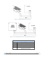
KLIC-DI incorporates in its design an infrared receiver, located next to the LED indicator.
This functionality eases the installation process of the device, since it is possible to check, from the
Zennio IR remote control (see Figure 2.1), that the control over the A/C machines is carried out
properly.
Note: In order to send the corresponding orders from the IR remote control to the interface, it is
compulsory to have the indicator LED lit (lighting red).
The actions that each button of the remote control carries out are shown in the Figure 2.1.
OFF/ON
Temperatures [17-32ºC]
OFF
ON
Min
Fan
Max
Fan
Fan Speed
Heat
Cool
Fan
Dry
Modes
17ºC
18ºC
19ºC
20ºC
21ºC
22ºC
23ºC
24ºC
25ºC
26ºC
27ºC
28ºC
29ºC
30ºC
31ºC
32ºC
Figure 2.1. pressing zones in the IR remote
ZENNiO AVANCE Y TECNOLOGÍA
vwww.zennio.com
11
3. ETS PARAMETERIZATION
For starting to parameterize the KLIC-DI interface it is necessary, once the ETS program has
been opened, importing the data base of the product (version 1.3 of the KLIC-DI VRV application
program).
Next, the device is added to the project where desired. Click the right mouse button on the device
and select "Edit parameters" for starting with the configuration.
In the following sections there is a detailed explanation about each of the different functionalities of
KLIC-DI VRV in ETS.
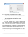
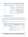
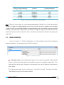
3.1. DEFAULT CONFIGURATION
This section shows the default configuration from which the device parameterization starts.
Figure 3.1. Default topology
In the default topology window (see Figure 3.1) appear the communication objects associated to the
sending and reception of the orders for basic control of the A/C unit: ON/OFF, Temperature, Mode
and Fan.
When entering the Parameters edition for the first time, the default General configuration window of
KLIC-DI is shown.
ZENNiO AVANCE Y TECNOLOGÍA
vwww.zennio.com
12
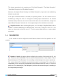
Figure 3.2. Configuration screen by default
As it can be seen in the figure 3.2, the configuration screen has 3 main windows:
General: to individually enable each of the advanced functionalities of the A/C machine.
Mode: to configure features related to the operating mode of the A/C machine.
Fan: to configure features related to the fan speed of the A/C machine.
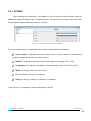
3.2. GENERAL WINDOW
From the General parameterization window one can enable the advanced functionalities
(Scenes, Temperature limitation, Auto OFF, Errors management and Initial configuration), which are
disabled by default. All these advanced functionalities are explained in detail in the following
sections.
When enabling the desired functionality in the right drop-down box, it will appear in the left menu the
access to the corresponding configuration window and the related communication objects will be
also enabled.
In the General window one can also configure the desired type of control for KLIC-DI: Master or
Slave remote control, the enabling or not of the slats (swing) and the Indoor Temperature
sending time.
ZENNiO AVANCE Y TECNOLOGÍA
vwww.zennio.com
13
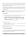
3.2.1. SCENES
After enabling this functionality, it will appear in the left menu the option Scenes, where to
enable and parametrize each of the 4 available scenes. The scene to be run will be sent to the KNX
bus through the object, enabled for this aim: "Scenes".
Figure 3.3. Scenes configuration window
For every enabled scene, the parameters that may be configured are the following:
Scene number. It indicates the scene number (from 1 to 64) to which the corresponding
configured orders will be sent to the A/C machine.
ON/OFF. Possibility to choose the A/C machine status: No change, OFF or ON.
Temperature. No change or sending of a new temperature value (from 16ºC to 32ºC).
Mode. No change, Heat, Dry, Fan or Cool.
Fan. No change, minimum or maximum.
Swing. No change, Swing or Fix Position (5 available).
In the figure 3.4, an example of scene configuration is shown.
ZENNiO AVANCE Y TECNOLOGÍA
vwww.zennio.com
14
Figure 3.4. Scene configuration example (Scene 1)
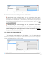
3.2.2. TEMPERATURE LIMITATION
Variable Refrigerant Volume units have defined upper and lower temperature limits that
cannot be exceeded (16ºC-32ºC). Nevertheless, KLIC-DI offers the possibility of establishing new
temperature limits if they are specified within the A/C unit predefined limits (please, look up the A/C
unit manual).
The temperature limits can be customized for the two modes that have a temperature associated:
Cool and Heat.
Figure 3.5. Temperature limitation configuration
ZENNiO AVANCE Y TECNOLOGÍA
vwww.zennio.com
15
For these limits to be taken into account, it will be necessary to explicitaly enable the temperature
limitation, by sending the value "1" through the specific communication object "Temperature
Limitation". To control the machine using its predefined temperature limitations, it is necessary to
send the value "0" through the same object.
Once established the new temperature limits for every mode and enabled the functionality, when a
value out of the range is sent from the KNX bus, the value that will be sent to the AC unit will be the
corresponding temperature limit and this new temperature will be notified, through the object
"Temperature sending".
Note: When configuring in ETS the temperature limitation, this functionlaity is automatically enabled
by default and the personalized ranges will control the unit performance when it switches on.
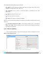
3.2.3. AUTO OFF
This option allows switching off the AC machine temporarily if a status change (from value
"0" to value "1") in the associated communication object happens ("Auto-OFF").
Figure 3.6. Auto OFF configuration
The only parameter to configure is:
Delay for Auto-OFF: to establish the time, in seconds, KLIC-DI waits before
automatically switching off the A/C machine.
Once the A/C machine has been automatically switched off, any ON order will be ignored until the
object “Auto-OFF” has the value “0”.
3.2.4. ERRORS MANAGEMENT
The errors management window allows enabling the sending of messages to the KNX bus
indicating any error that may arise: internal errors of the communication between KLIC-DI and the
A/C unit, or external errors (errors in the own A/C unit).
ZENNiO AVANCE Y TECNOLOGÍA
vwww.zennio.com
16
Figure 3.7. Errors management configuration window
The detection of internal, external or both types of errors can be enabled:
Internal errors: when enabling this option, two new communication objects appear:
"Internal error", 1-bit object and "Type of internal error", 1-byte object. The first one indicates if
an internal error has occurred (value "1": there is an error, value "0": there is not). The second
object indicates the code that identifies the error (numerical value between 1 and 4. See Table
2.1: Type of Internal Errors).
External errors: when enabling this option, two new communication objects appear:
"External Error" and "Type of external error". The first one indicates if an external error has
occurred (value "1": there is an error, value "0": there is not). The second object indicates the
code that identifies the error (see the specific manual of the A/C unit installed or see Annex II.
Correspondence Error Codes of the A/C Units).
3.2.5. START-UP CONFIGURATION
This functionality allows configuring the initial statuses of the A/C machine after the
installation or a power failure. This configuration can be default or custom. If a custom configuration
is chosen, the window of the figure 3.8 will be shown.
Figure 3.8. Initial configuration window
ZENNiO AVANCE Y TECNOLOGÍA
vwww.zennio.com
17
The variables than can be initialized are the following:
ON/OFF: last (the status the machine had before the power failure; after the first
installation, this status will be OFF), ON or OFF.
Temperature: Last or custom (a new field appears to establish the new initial
temperature).
Mode: Last, Heat, Dry, Fan or Cool.
Fan: Last, minimum or maximum.
Swing: Last, Swing or Fix Position (5 available).
Moreover, it can be configured the sending of the statuses to the KNX bus and when they must be
carried out:
Send initial configuration to BUS?: If this sending is enabled ("Yes"), a new field will
appear next: "Delay", where to configure the time, in seconds, KLIC-DI delays the sending of
the statuses to the KNX bus.
3.2.6. TYPE OF CONTROL
From the General window one can also select the type if control to be applied to KLIC-DI:
Master or Slave Remote control.
Figure 3.9. Type of control: master or slave
ZENNiO AVANCE Y TECNOLOGÍA
vwww.zennio.com
18
When the option Master remote control is selected, the drop-down box "Master/Slave of Mode" is
enabled, because only when KLIC-DI is configured as Master, it can be Master of Mode.
The parameter Master/Slave of Mode allows configuring the KLIC-DI as Master or Slave of mode.
When the device is configured as Master of mode, all the modes of the system can be configured
from the KLIC-DI. However, when the device is configured as Slave of mode, it could only set the
mode configured in the device acting as master control (Cool or Heat) and the Fan mode.
In the Table 3.1, the modes that can be configured in the device acting as Slave of mode depending
on the configured mode in the Master of mode are shown.
Mode configured in the
Master of Mode
Heat
Cool
Fan
Configurable modes from the
Sleve of mode
Heat and Fan
Cool, Fan and Dry
Fan
Table 3.1. Modes for Master and Slave of mode
Note: When KLIC-DI is configured as Master of mode, it is not possible to set from the wired remote
control of the A/C unit another Master of mode.
3.2.7. SWING
Thanks to this parameter, one can select whether to carry put a control over the slats of the
A/C machine or not.
Note: Make sure that the model of the A/C unit has slats (swing option) in the user manual, before
configuring it. If it does not have this option, this configuration could result in an incorrect control of
the system performance.
ZENNiO AVANCE Y TECNOLOGÍA
vwww.zennio.com
19
Figure 3.10. Swing
The slats have 5 fixed positions and the options of constant movement and stopped.
When enabling this option ("Yes"), two communication objects appear (1-byte each): "Swing [1 byte]
Sending" and "Swing [1 byte] Reception" and two other objects of 1-bit each: "Swing sending" and
"Swing [1 bit] reception". All of them allow controlling and showing at any moment the slats working
status, specifically:
The 1-bit object "Swing sending" allows selecting the swing performance in the following
way:
Sending the value "0": If the slats are in a fixed position, the position number is
risen. In case of being in swing mode, the slats change to the last fixed position they had
before entering in swing mode.
Sending the value "1": The slats begin to work in swing mode.
The status object ("Swing [1 bit] reception") will indicate the slats working: swing (value "1") or
fixed position (value "0").
The 1-byte object "Swing [1 byte] sending" allows establishing the slats position be
means of sending a value in percentage, according to the rates shown in Table 3.2.
The status object ("Swing [1 byte] reception") will indicate the slats current status, in
percentage.
ZENNiO AVANCE Y TECNOLOGÍA
vwww.zennio.com
20
Value of the object
"Swing [1 byte] Sending"
0%
1-20%
21-40%
41-60%
61-80%
81-100%
Number of Fixed
position
Position 1
Position 2
Position 3
Position 4
Position 5
Swing
Value of the object "Swing
[1 byte] Reception"
0%
20%
40%
60%
80%
100%
Table 3.2. Value of the objects "Swing [1 byte]"
Note: Take into account that due to the internal performance of the A/C unit, if the fixed position
number 3 or higher is configured being in mode Cool, the A/C unit will not answer to this command
in order to avoid a cold air flow directed to a particular point of the room (where a person could be
located). In the same way, if the position 2 or lowewr is configured being in the mode Heat, the A/C
unit will not answer to this command in order to avoid amn accumulation of hot air in the upper part
of the room.
3.3. MODE WINDOW
As seen in section 3.1. Default Configuration, the specific Mode window allows configuring
featured regarding to the operating mode of the A/C machine.
Figure 3.11. Mode window
Individual modes: when selecting this option, 8 new 1-bit communication objects will be
shown. 4 of them are associated to the sending of each of the available modes (Cool, Fan,
Heat and Dry) and the other 4 objects, to the reception from the A/C machine of the status of
every mode.
The objects associated with the sending are: "Cool Mode Sending", "Fan Mode Sending",
"Heat Mode Sending" and "Dry Mode Sending".
ZENNiO AVANCE Y TECNOLOGÍA
vwww.zennio.com
21
The objects associated to the reception are: "Cool Mode Reception", "Fan Mode Reception",
"Heat Mode Reception" and "Dry Mode Reception".
Moreover, the objects "Mode Sending" and "Mode Reception" (1-byte each and available by
default) may be used.
If the option Individual modes is activated, the operating mode of the A/C machine can be
modified (by writing the value "1" through the sending object associated to the desired
individual mode). Moreover, the current mode will be also sent to the KNX bus, through the
object "Mode Reception" and with the 1-bit reception object of the individual current mode.
Simplified modes: when selecting this option, the 1-bit object "Simplified Mode" will be
enabled. It allows establishing the desired mode: Cool mode, writing the value "0" in the
object, or Heat mode, writing the value "1". For this control object there is no status object
associated.
3.4. FAN WINDOW
In this window it can be configured several features related to the fan speed of the A/C
machine.
Figure 3.12. Fan window
Number of levels: this option allows configuring the number of fan levels the A/C unit
has. These may be 2 or 3 levels. The fan speed has associated two 1-byte objects: "Fan [1
Byte] Sending" and "Fan Reception", for controlling and indicating the fan speed, respectively.
The control object ("Fan Sending") records the fan speed in percentage. This value will be
interpolated in such a way that corresponds to the selected number of levels, as it can be
seen next. The status object ("Fan Reception") will show the current fan sped, according to
the interpolated percentages.
ZENNiO AVANCE Y TECNOLOGÍA
vwww.zennio.com
22
2 levels: The fan speed percentages will be interpolated as shown in Table 3.3.
Initial Speed
Percentage
0-49%
50-100%
Interpolated Speed Percentage
Level
25%
100%
Minimum
Maximum
Table 3.3. Fan speed percentages for 2 levels
3 levels: The fan speed percentages will be interpolated as shown in Table 3.4.
Initial Speed
Percentage
0-32%
33-65%
66-100%
Interpolated Speed Percentage
Level
25%
50%
100%
Minimum
Medium
Maximum
Table 3.4. Fan speed percentages for 3 levels
Step control: the selection of this option ("Yes") enables the 1-bit object "Fan [1 bit]
Sending" that allows increasing (sending the value "1") or decreasing (value "0") the fan
speed in one level (for example, for 3 levels, in the minimum level of fan speed, the value "1"
is sent via the object "Fan [1 bit] Sending", the fan speed level will go to medium).
The step control is not cyclical. This means that, being in the Auto level (0%), when
decreasing the fan speed level, the AC machine will stay in the auto mode until the speed
level is increased. The same way, when the speed level is in the maximum level (100%), the
machine will remain in this level until receiving an order to decrease the speed.
ZENNiO AVANCE Y TECNOLOGÍA
vwww.zennio.com
23
ANNEX I. COMMUNICATION OBJECTS
SECTION
VALUES
NUMBER
SIZE
IN/OUT
FLAGS
RANGE
1st TIME
RESET
0
1 bit
I
W
0/1
0
Last
ON/OFF Sending
Turn ON/OFF the machine
1
2 bytes
I
W
16-32ºC
25ºC
Last
Temperature Sending
Value sent to the machine
2
1 byte
I
W
0-255
Cool (3)
Last
Mode Sending
0=Aut;1=Heat;3=Cool;9=Fan;14=Dry
3
1 byte
I
W
0-100%
0
Last
Fan [1 byte] Sending
0-32%Min,33-65%Med,>65%Max For 3
levels
4
1 bit
I
W
0/1
0
Last
Swing sending
0=Among fixed pos.,1=Motion
5
1 bit
RT
0/1
Status
dependant
Last
ON/OFF Reception
Machine state (ON/OFF)
6
2 bytes
RT
16-32ºC
Status
dependant
Last
Temperature Reception
Value received from the machine
7
1 byte
RT
0-255
Status
dependant
Last
Mode reception
Actual mode:
0=Aut;1=Heat;3=Cool;9=Fan;14=Dry
8
1 byte
RT
0-100%
Status
dependant
Last
Fan Reception
25%Min,100%Máx For 2 levels
25%Min,50%Med,100%Max For 3 levels
9
1 byte
RT
0-100%
Status
dependant
Last
Swing [1 byte] Sending
0-80%=Fixed Pos.,100%=Motion
10
1 bit
I
WT
0/1
0
Last
Cool mode sending
1=Set Cool Mode; 0=Nothing
11
1 bit
I
WT
0/1
0
Last
Heat mode sending
1=Set Heat Mode; 0=Nothing
12
1 bit
I
WT
0/1
0
Last
Fan mode sending
1=Set Fan Mode; 0=Nothing
13
1 bit
I
WT
0/1
0
Last
Dry mode sending
1=Set Dry Mode; 0=Nothing
14
1 bit
I
W
0/1
0
Last
Simplified Mode
0=Cool; 1=Heat
NAME
DESCRIPTION
0-49%=Low, 50-100%=High For 2 levels
GENERAL
MODE
ZENNiO AVANCE Y TECNOLOGÍA
vwww.zennio.com
24
SECTION
MODE
NUMBER
SIZE
15
1 bit
16
1 bit
IN/OUT
VALUES
FLAGS
NAME
DESCRIPTION
RANGE
1st TIME
RESET
RT
0/1
0
Last
Cool mode reception
1=Cool mode enabled; 0=Disabled
RT
0/1
0
Last
Heat mode reception
1=Heat mode enabled; 0=Disabled
RT
0/1
0
Last
Fan mode reception
1=Fan mode enabled; 0=Disabled
17
1 bit
18
1 bit
RT
0/1
0
Last
Dry mode reception
1=Dry mode enabled; 0=Disabled
FAN
19
1 bit
I
W
0/1
0
Indifferent
Fan [1 bit] Sending
0=Down; 1=Up
SCENES
20
1 byte
I
W
0-63
Indifferent
Indifferent
Scenes
TEMPERATURE
LIMITATION
21
1 bit
I
W
0/1
0
Last
Temperature limitation
0=Disable; 1=Enable
AUTO OFF
22
1 bit
I
W
0/1
0
Last
Auto-OFF
0=Disable; 1=Enable
23
1 bit
O
RT
0/1
Connection
status
dependant
Connection
status
dependant
Internal error
0=No Error; 1=Error
24
1 byte
O
RT
1-4
Error type
dependant
Error type
dependant
Type of Internal Error
1=Recep.Err, 2=TimeOut, 3=Checksum,
4=Resp.Err
25
1 bit
O
RT
0/1
Machine status
dependant
Machine status
dependant
External error
0=No Error; 1=Error
26
1 byte
O
RT
0-255
Error type
dependant
Error type
dependant
Type of External Error
Check errors table
27
2 bytes
O
RT
0-120.0ºC
Machine type
dependant
Last
Indoor temperature reception
Machine temperature
28
2 bytes
I
WU
0-120.0ºC
25ºC
Last
Reference
reception
Reference temperature:
29
1 byte
I
WU
0-100%
0
Last
Swing [1 byte] Sending
0-80%=Fixed Pos.;100%=Mot.
30
1 bit
O
RT
0/1
0
Last
Swing [1 bit] Reception
0=Fixed Position; 1=Motion
ERRORS
MANAGEMENT
TEMPERATURES
RECEPTION
Set Scene "value"
temperature
SWING
ZENNiO AVANCE Y TECNOLOGÍA
vwww.zennio.com
25
ANNEX II. CORRESPONDENCE ERROR CODES OF THE A/C UNITS
Next table shows the correspondence between the external error code provided by KLIC-DI at the bus KNX and the breakdown codes of
the A/C units:
ERROR
BUS
CODE
ERROR
BUS
CODE
ERROR
BUS
CODE
ERROR
BUS
CODE
ERROR
BUS
CODE
ERROR
BUS
CODE
ERROR
BUS
CODE
ERROR
BUS
CODE
ERROR
BUS
CODE
ERROR
BUS
CODE
1
1
27
AH
53
E5
79
HF
105
J9
131
P3
157
UJ
183
87
209
61
235
5H
2
2
28
AC
54
E6
80
F0
106
JA
132
P4
158
UE
184
88
210
62
236
5C
3
3
29
AJ
55
E7
81
F1
107
JH
133
P5
159
UF
185
89
211
63
237
5J
4
4
30
AE
56
E8
82
F2
108
JC
134
P6
160
90
186
8A
212
64
238
5E
5
5
31
AF
57
E9
83
F3
109
JJ
135
P7
161
91
187
8H
213
65
239
5F
6
6
32
C0
58
EA
84
F4
110
JE
136
P8
162
92
188
8C
214
66
240
40
7
7
33
C1
59
EH
85
F5
111
JF
137
P9
163
93
189
8J
215
67
241
41
8
8
34
C2
60
EC
86
F6
112
L0
138
PA
164
94
190
8E
216
68
242
42
9
9
35
C3
61
EJ
87
F7
113
L1
139
PH
165
95
191
8F
217
69
243
43
10
0A
36
C4
62
EE
88
F8
114
L2
140
PC
166
96
192
70
218
6A
244
44
11
0H
37
C5
63
EF
89
F9
115
L3
141
PJ
167
97
193
71
219
6H
245
45
ZENNiO AVANCE Y TECNOLOGÍA
vwww.zennio.com
26
ERROR
BUS
CODE
ERROR
BUS
CODE
ERROR
BUS
CODE
ERROR
BUS
CODE
ERROR
BUS
CODE
ERROR
BUS
CODE
ERROR
BUS
CODE
ERROR
BUS
CODE
ERROR
BUS
CODE
ERROR
BUS
CODE
13
0J
39
C7
65
H1
91
FH
117
L5
143
PF
169
99
195
73
221
6J
247
47
14
0E
40
C8
66
H2
92
FC
118
L6
144
U0
170
9A
196
74
222
6E
248
48
15
0F
41
C9
67
H3
93
FJ
119
L7
145
U1
171
9H
197
75
223
6F
249
49
16
A0
42
CA
68
H4
94
FE
120
L8
146
U2
172
9C
198
76
224
50
250
4A
17
A1
43
CH
69
H5
95
FF
121
L9
147
U3
173
9J
199
77
225
51
251
4H
18
A2
44
CC
70
H6
96
J0
122
LA
148
U4
174
9E
200
78
226
52
252
4C
19
A3
45
CJ
71
H7
97
J1
123
LH
149
U5
175
9F
201
79
227
53
253
4J
20
A4
46
CE
72
H8
98
J2
124
LC
150
U6
176
80
202
7A
228
54
254
4E
21
A5
47
CF
73
H9
99
J3
125
LJ
151
U7
177
81
203
7H
229
55
255
4F
22
A6
48
E0
74
HA
100
J4
126
LE
152
U8
178
82
204
7C
230
56
23
A7
49
E1
75
HH
101
J5
127
LF
153
U9
179
83
205
7J
231
57
24
A8
50
E2
76
HC
102
J6
128
P0
154
UA
180
84
206
7E
232
58
25
A9
51
E3
77
HJ
103
J7
129
P1
155
UH
181
85
207
7F
233
59
26
AA
52
E4
78
HE
104
J8
130
P2
156
UC
182
86
208
60
234
5A
ZENNiO AVANCE Y TECNOLOGÍA
vwww.zennio.com
27
DOCUMENTATION
TECHNICAL SUPPORT
TECHNICAL
http://zennioenglish.zendesk.com
ZENNIO
BECOME USER!
28


![IA [impact assessment] template user manual](http://vs1.manualzilla.com/store/data/006900770_1-df6c75c7a80350a4ef518ef06058013e-150x150.png)