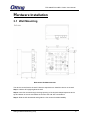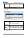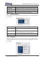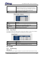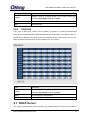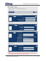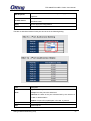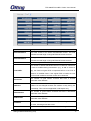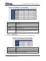
1
TPS-3082GT-M12-BP1 Industrial Managed Ethernet Switches User Manual Version 4.0 March, 2014 www.oring-networking.com TPS-3082GT-M12-BP1 Series User Manual COPYRIGHT NOTICE Copyright © 2014 ORing Industrial Networking Corp. All rights reserved. No part of this publication may be reproduced in any form without the prior written consent of ORing Industrial Networking Corp. TRADEMARKS is a registered trademark of ORing Industrial Networking Corp. All other trademarks belong to their respective owners. REGULATORY COMPLIANCE STATEMENT Product(s) associated with this publication complies/comply with all applicable regulations. Please refer to the Technical Specifications section for more details. WARRANTY ORing warrants that all ORing products are free from defects in material and workmanship for a specified warranty period from the invoice date (5 years for most products). ORing will repair or replace products found by ORing to be defective within this warranty period, with shipment expenses apportioned by ORing and the distributor. This warranty does not cover product modifications or repairs done by persons other than ORing-approved personnel, and this warranty does not apply to ORing products that are misused, abused, improperly installed, or damaged by accidents. Please refer to the Technical Specifications section for the actual warranty period(s) of the product(s) associated with this publication. DISCLAIMER Information in this publication is intended to be accurate. ORing shall not be responsible for its use or infringements on third-parties as a result of its use. There may occasionally be unintentional errors on this publication. ORing reserves the right to revise the contents of this publication without notice. CONTACT INFORMATION ORing Industrial Networking Corp. 4F., NO.3, Lane235, Baociao Rd., Sindian City, Taipei County 23145, Taiwan, R.O.C. Tel: + 886 2 2918 3036 // Fax: + 886 2 2918 3084 Website: www.oring-networking.com Technical Support E-mail: [email protected] Sales Contact E-mail: [email protected] (Headquarters) [email protected] (China) ORing Industrial Networking Corp 1 TPS-3082GT-M12-BP1 Series User Manual Table of Content Getting Started ............................................................................................... 5 1.1 About the TPS-3082GT-M12-BP1 Series .............................................................. 5 1.2 Software Features ................................................................................................ 5 1.3 Hardware Features ............................................................................................... 6 Hardware Overview ........................................................................................ 7 2.1 Front Panel ........................................................................................................... 7 2.2 Front Panel LEDs ................................................................................................. 8 2.3 Bypass Technology ............................................................................................... 8 Hardware Installation ................................................................................... 10 3.1 Wall Mounting ..................................................................................................... 10 3.2 Wiring ................................................................................................................. 11 3.2.1 Grounding .................................................................................................. 12 3.2.2 Relay Output .............................................................................................. 12 3.2.3 Power Input ................................................................................................ 12 3.3 Cables ................................................................................................................ 12 3.3.1 Ethernet Connection ................................................................................... 12 3.3.2 Console Port .............................................................................................. 13 3.3.3 O-Ring/O-Chain ......................................................................................... 14 Redundancy ................................................................................................. 17 4.1 O-Ring................................................................................................................ 17 4.1.1 Introduction ................................................................................................ 17 4.1.2 Configurations ............................................................................................ 17 4.2 OPEN-Ring......................................................................................................... 19 4.2.1 Introduction ................................................................................................ 19 4.2.2 Configurations ............................................................................................ 19 4.3 O-Chain .............................................................................................................. 20 4.3.1 Introduction ................................................................................................ 20 4.3.2 Configurations ............................................................................................ 20 4.4 MRP ................................................................................................................... 21 4.4.1 Introduction ................................................................................................ 21 4.4.2 Configurations ............................................................................................ 21 4.5 STP/RSTP/MSTP ............................................................................................... 22 4.5.1 STP/RSTP ................................................................................................. 22 ORing Industrial Networking Corp 2 TPS-3082GT-M12-BP1 Series User Manual 4.5.2 MSTP......................................................................................................... 26 4.6 Fast Recovery .................................................................................................... 30 Management ................................................................................................. 32 5.1 System Information......................................................................................... 33 5.2 Basic Setting .................................................................................................. 34 5.2.1 Admin Password ........................................................................................ 35 5.2.2 IP Setting ................................................................................................... 35 5.2.3 Time Setting ............................................................................................... 36 5.2.4 LLDP .......................................................................................................... 39 5.2.5 Modbus TCP .............................................................................................. 40 5.2.6 Backup & Restore ...................................................................................... 40 5.2.7 Upgrade Firmware...................................................................................... 42 5.3 Multicast ......................................................................................................... 42 5.3.1 IGMP Snooping .......................................................................................... 42 5.3.2 MVR........................................................................................................... 43 5.3.3 Static Multicast Filtering .............................................................................. 44 5.4 Port Setting .................................................................................................... 45 5.4.1 Port Control ................................................................................................ 45 5.4.2 Port Status ................................................................................................. 45 5.4.3 Port Alias.................................................................................................... 46 5.4.4 Rate Limit ................................................................................................... 46 5.4.5 Port Trunk .................................................................................................. 47 5.4.6 Loop Guard ................................................................................................ 48 5.5 VLAN ............................................................................................................. 48 5.5.1 VLAN Setting.............................................................................................. 48 5.5.2 Port Based ................................................................................................. 50 5.6 Traffic Prioritization ......................................................................................... 51 5.6.1 QoS Policy ................................................................................................. 52 5.6.2 Port-base priority ........................................................................................ 53 5.6.3 COS/802.1p ............................................................................................... 53 5.6.4 TOS/DSCP................................................................................................. 54 5.7 DHCP Server.................................................................................................. 54 5.7.1 Basic Setting .............................................................................................. 55 5.7.2 Client List ................................................................................................... 56 5.7.3 Port and IP bindings ................................................................................... 56 5.7.4 DHCP Relay Agent ..................................................................................... 56 5.8 SNMP............................................................................................................. 57 ORing Industrial Networking Corp 3 TPS-3082GT-M12-BP1 Series User Manual 5.8.1 Agent Setting....................................................................................................... 57 5.8.2 Trap Setting ......................................................................................................... 59 5.8.3 SNMPV3.............................................................................................................. 59 5.9 Security .................................................................................................................... 62 5.9.1 IP Security.................................................................................................. 62 5.9.2 Port Security............................................................................................... 63 5.9.3 MAC Blacklist ............................................................................................. 63 5.9.4 802.1x ........................................................................................................ 64 5.9.5 IP Guard..................................................................................................... 67 5.10 Warning .................................................................................................................... 68 5.10.1 Fault Relay Alarm ................................................................................... 69 5.10.2 SYSLOG ................................................................................................ 69 5.10.3 SMTP..................................................................................................... 70 5.10.4 Event Notification ................................................................................... 71 5.11 Monitor and Diag ..................................................................................................... 72 5.11.1 System Event Log .................................................................................. 72 5.11.2 MAC Address Table ................................................................................ 72 5.11.3 Ping ....................................................................................................... 78 5.12 PoE........................................................................................................................... 79 5.12.1 Basic Setting .......................................................................................... 79 5.12.2 Port Setting ............................................................................................ 80 5.12.3 Port Status ............................................................................................. 81 5.12.4 Boot Delay ............................................................................................. 82 5.12.5 Ping Alive Check .................................................................................... 83 5.12.6 Schedule ................................................................................................ 83 5.13 Save Configuration.................................................................................................. 84 5.14 Factory Default ........................................................................................................ 85 5.15 System Reboot ........................................................................................................ 85 Command Line Interface Management ...................................................... 86 ORing Industrial Networking Corp 4 TPS-3082GT-M12-BP1 Series User Manual Getting Started 1.1 About the TPS-3082GT-M12-BP1 Series The TPS-3082GT-M12-BP1 series, including the TPS-3082GT-M12-BP1 and the TPS-3082GT-M12-BP1-24V models, are managed Ethernet switches designed for industrial applications, such as rolling stock, vehicle, and railway applications. The switches boast EN50155 compliance and M12 connectors to ensure tight and robust connections, and guarantee reliable operation against environmental disturbances, such as vibration and shock. All models feature eight 10/100Base-T(X) P.S.E. ports which are able to provide sufficient power for power-hungry devices. Therefore, you can attach an IEEE 802.3af-compliant device to the switch without requiring additional power. The devices also provide 1 set of bypass ports that ensure constant network connectivity if power outage or node failure occurs. In such situations, the device will bypass the inactive switch and continue to transfer network traffic to the next switch in the relay. With complete support for Ethernet redundancy protocols such as O-Ring (recovery time < 30ms over 250 units of connection) and MSTP (RSTP/STP compatible), the switches can protect your mission-critical applications from network interruptions or temporary malfunctions with fast recovery ability. Featuring a wide operating temperature from -40oC to 70oC, the series can be managed centrally via Open-Vision, web browsers, Telnet and console (CLI) configuration. 1.2 Software Features Supports O-Ring (Recovery time < 10ms over 250 units connection) Supports Open-Ring to interoperate with other vendors’ ring technology in open architecture Supports O-Chain to allow multiple redundant network rings Supports MSTP/RSTP/STP (IEEE 802.1s/w/D) Supports PTP client (Precision Time Protocol) clock synchronization IGMP v2/v3 (IGMP snooping) for filtering multicast traffic Supports SNMP v1/v2c/v3 for network security Supports RMON for traffic monitoring 802.1Q VLAN Network Management Supports LLDP protocol Supports event notification through SYSLOG, e-mail, SNMP traps, and relay output Supports management via Web-based interfaces, Telnet, Console (CLI), and Windows utility (Open-Vision) ORing Industrial Networking Corp 5 TPS-3082GT-M12-BP1 Series User Manual 1.3 Hardware Features Dual DC power inputs EN50155 compliance 8 x 10/100Base-T(X) Ethernet ports with P.S.E. functions to provide up to 15.4 Watts per port 2 x 10/100/1000Base-T Ethernet ports with bypass function 1 x console port M12 connectors for reliable operation against environmental disturbances Wall mounting enabled Wide Operating Temperature: -40 to 70 C Storage Temperature: -40 to 85 C Operating Humidity: 5% to 95%, non-condensing Casing: IP-40 Dimensions: 170mm (W) x 75mm (D) x196mm (H) o o ORing Industrial Networking Corp 6 TPS-3082GT-M12-BP1 Series User Manual Hardware Overview 2.1 Front Panel The switches come with the following ports on the front panel: Port Description 10/100Base-T(X) 8 x 10/100Base-T(X) RJ-45 fast Ethernet ports in M12 connectors RJ-45 ports 10/100/1000Base-T 2 x 10/100Base-T(X) RJ-45 fast Ethernet ports in M12 connectors RJ-45 ports Console 1 x console port (Baud rate setting: 9600bps, 8, N, 1) Reset Press reset button 2 to 3 seconds to reset the switch. Press reset button 5 seconds to return the switch to factory setting. ORing Industrial Networking Corp 7 TPS-3082GT-M12-BP1 Series User Manual 1. Reset button 9. Power connector 2. Power 1 status LED 10. PoE Ethernet ports 3. Power 2 status LED 11. LNK/ACT indicator for PoE Ethernet port 4. R.M. status LED 12. PoE status LED 5. Ring status LED 13. Duplex/collision status LED 6. Fault satus LED 14. Gigabit Ethernet ports 7. Relay output port 15. LNK/ACT indicator for Gigabit Ethernet port 8. Console port 16. Speed indicator for Gigabit Ethernet port 2.2 Front Panel LEDs LED Color Status Description PWR1 Green On DC power module 1 activated PWR2 Green On DC power module 2 activated R.M Green On System running in Ring Master mode Ring Green On System running in Ring mode Fault Amber On Errors occur (power failure or port link down) On Port is linked Blinking Transmitting data On Port providing power to PD On Port running in full-duplex mode Blinking Collision occurs 10/100Base-T(X) Ports LNK/ACT Green PoE Green DPX/COL Amber 10/100/1000Base-T Ports LNK/ACT Green 100M Amber On Port is linked Blinking Transmitting data On Port speed at 100M 2.3 Bypass Technology When a device connected to other devices through a switch without bypass function, the device will lose connection if he switch loses power as traffic will not be able to flow through the link (as shown in the figure below). ORing Industrial Networking Corp 8 TPS-3082GT-M12-BP1 Series User Manual Switches with bypass functions such as the TPS-3082-M12-BP1 provide one or more sets of bypass ports that ensure constant network connectivity during power failure. ORing Industrial Networking Corp 9 TPS-3082GT-M12-BP1 Series User Manual Hardware Installation 3.1 Wall Mounting Wall-mount Kit Measurements The device can be fixed to the wall. Follow the steps below to install the device on the wall. Step 1: Hold the AP upright against the wall Step 2: Insert four screws through the large opening of the keyhole-shaped apertures at the top and bottom of the unit and fasten the screw to the wall with a screwdriver. Step 3: Slide the AP downwards and tighten the four screws for added stability. ORing Industrial Networking Corp 10 TPS-3082GT-M12-BP1 Series User Manual Instead of screwing the screws in all the way, it is advised to leave a space of about 2mm to allow room for sliding the AP between the wall and the screws. 3.2 Wiring WARNING Do not disconnect modules or wires unless power has been switched off or the area is known to be non-hazardous. The devices may only be connected to the supply voltage shown on the type plate. ATTENTION 1. Be sure to disconnect the power cord before installing and/or wiring your switches. 2. Calculate the maximum possible current in each power wire and common wire. Observe all electrical codes dictating the maximum current allowable for each wire size. 3. If the current goes above the maximum ratings, the wiring could overheat, causing serious damage to your equipment. 4. Use separate paths to route wiring for power and devices. If power wiring and device wiring paths must cross, make sure the wires are perpendicular at the intersection point. 5. Do not run signal or communications wiring and power wiring through the same wire conduit. To avoid interference, wires with different signal characteristics should be routed separately. 6. You can use the type of signal transmitted through a wire to determine which wires should be kept separate. The rule of thumb is that wiring sharing similar electrical characteristics can be bundled together 7. You should separate input wiring from output wiring 8. It is advised to label the wiring to all devices in the system ORing Industrial Networking Corp 11 TPS-3082GT-M12-BP1 Series User Manual 3.2.1 Grounding Grounding and wire routing help limit the effects of noise due to electromagnetic interference (EMI). Run the ground connection from the ground screw on the power connector to the grounding surface prior to connecting devices. 3.2.2 Relay Output The device uses a M12 A-coded 5-pin male connector on the front panel for relay output. The relay contacts will detect user-configured events and form an open circuit when an event is triggered. 3.2.3 Power Input The switch provides two sets of power supply on a M23 5-pin female connector to enable dual power inputs. Step 1: Insert a power cable to the power connector on the device. Step 2: Rotate the outer ring of the cable connector until a snug fit is achieved. Make sure the connection is tight. 3.3 Cables 3.3.1 Ethernet Connection The series provide Ethernet ports in M12 connectors. According to the link type, the switch uses CAT 3, 4, 5,5e UTP cables to connect to any other network devices (PCs, servers, switches, routers, or hubs). Please refer to the following table for cable specifications. Cable Types and Specifications ORing Industrial Networking Corp 12 TPS-3082GT-M12-BP1 Series User Manual Cable 10BASE-T Type Max. Length Cat. 3, 4, 5 100-ohm 100BASE-TX Cat. 5 100-ohm UTP 1000BASE-T Connector UTP 100 m (328 4-pin female M12 A-coding ft) connector UTP 100 m (328 4-pin female M12 A-coding ft) connector Cat. 5/Cat. 5e UTP 100 m 4-pin female M12 A-coding 100-ohm UTP (328ft) connector Below is the pin assignment for Ethernet ports. 4-Pin PoE Port Definition Pin No. Description #1 TD+ with PoE power input + #2 TD- with PoE power input + #3 RD+ with PoE power input - #4 RD- with PoE power input - 4-Pin Gigabit Port Definition 3.3.2 Console Port ORing Industrial Networking Corp 13 TPS-3082GT-M12-BP1 Series User Manual 3.3.3 O-Ring/O-Chain O-Ring You can connect three or more switches to form a ring topology to gain network redundancy capabilities through the following steps. 1. Connect each switch to form a daisy chain using an Ethernet cable. 2. Set one of the connected switches to be the master and make sure the port setting of each connected switch on the management page corresponds to the physical ports connected. For infomration about the port setting, please refer to 4.1.2 Configurations. 3. Connect the last switch to the first switch to form a ring topology. Coupling Ring If you already have two O-Ring topologies and would like to connect the rings, you can form them into a couping ring. All you need to do is select two switches from each ring to be connected, for example, switch A and B from Ring 1 and switch C and D from ring 2. Decide which port on each switch to be used as the coupling port and then link them together, for example, port 1 of switch A to port 2 of switch C and port 1 of switch B to port 2 of switch D. Then, enable Coupling Ring option by checking the checkbox on the management page and select the coupling ring in correspondance to the connected port. For more inforamtion on port setting, please refer to 4.1.2 Configurations. Once the setting is completed, one of the connections will act as the main path while the other will act as the backup path. ORing Industrial Networking Corp 14 TPS-3082GT-M12-BP1 Series User Manual Dual Homing If you want to connect your ring topology to a RSTP network environment, you can use dual homing. Choose two switches (Switch A & B) from the ring for connecting to the switches in the RSTP network (core switches). The connection of one of the switches (Switch A or B) will act as the primary path, while the other will act as the backup path that is activated when the primary path connection fails. O-Chain When connecting multiple O-Rings to meet your expansion demand, you can create an ORing Industrial Networking Corp 15 TPS-3082GT-M12-BP1 Series User Manual O-Chain topology through the following steps. 1. Select two switches from the chain (Switch A & B) that you want to connect to the O-Ring and connect them to the switches in the ring (Switch C & D). 2. In correspondence to the port connected to the ring, configure an edge port for both of the connected switches in the chain by checking the box in the management page (see 4.1.2 Configurations). 3. Once the setting is completed, one of the connections will act as the main path, and the ohter as the back up path. ORing Industrial Networking Corp 16 TPS-3082GT-M12-BP1 Series User Manual Redundancy Redundancy for minimized system downtime is one of the most important concerns for industrial networking devices. Hence, ORing has developed proprietary redundancy technologies including O-Ring and Open-Ring featuring faster recovery time than existing redundancy technologies widely used in commercial applications, such as STP, RSTP, and MSTP. ORing’s proprietary redundancy technologies not only support different networking topologies, but also assure the reliability of the network. 4.1 O-Ring 4.1.1 Introduction O-Ring is ORing's proprietary redundant ring technology, with recovery time of less than 30 milliseconds (in full-duplex Gigabit operation) or 10 milliseconds (in full-duplex Fast Ethernet operation) and up to 250 nodes. The ring protocols identify one switch as the master of the network, and then automatically block packets from traveling through any of the network’s redundant loops. In the event that one branch of the ring gets disconnected from the rest of the network, the protocol automatically readjusts the ring so that the part of the network that was disconnected can reestablish contact with the rest of the network. The O-Ring redundant ring technology can protect mission-critical applications from network interruptions or temporary malfunction with its fast recover technology. 4.1.2 Configurations O-Ring supports three ring topologies: Ring Master, Coupling Ring, and Dual Homing. You can configure the settings in the interface below. ORing Industrial Networking Corp 17 TPS-3082GT-M12-BP1 Series User Manual Label Description Enable Ring Check to enable O-Ring topology. Only one ring master is allowed in a ring. However, if more than one Enable Ring switches are set to enable Ring Master, the switch with the lowest MAC address will be the active ring master and the others will be Master backup masters. 1st Ring Port The primary port when the switch is ring master 2nd Ring Port The backup port when the switch is ring master Enable Check to enable Coupling Ring. Coupling Ring can divide a big Coupling ring into two smaller rings to avoid network topology changes Ring affecting all switches. It is a good method for connecting two rings. Ports for connecting multiple rings. A coupling ring needs four Couple Port switches to build an active and a backup link. Links formed by the coupling ports will run in active/backup mode. Enable Homing Dual Check to enable Dual Homing. When Dual Homing is enabled, the ring will be connected to normal switches through two RSTP links (ex: backbone Switch). The two links work in active/backup mode, and connect each ring to the normal switches in RSTP mode. Apply Note: Click to activate the configurations. due to heavy loading, setting one switch as ring master and coupling ring at the same time is not recommended. ORing Industrial Networking Corp 18 TPS-3082GT-M12-BP1 Series User Manual 4.2 OPEN-Ring 4.2.1 Introduction Open-Ring is a technology developed by ORing to enhance ORing switches’ interoperability with other vendors’ products. With this technology, you can add any ORing switches to the network based on other ring technologies. 4.2.2 Configurations Label Enable Description Check to enable Open-Ring topology Vender Choose the venders that you want to join in their rings ORing Industrial Networking Corp 19 TPS-3082GT-M12-BP1 Series User Manual 1 Ring Port The first port to connect to the ring 2nd Ring Port The second port to connect to the ring st 4.3 O-Chain 4.3.1 Introduction O-Chain is ORing’s revolutionary network redundancy technology which enhances network redundancy for any backbone networks, providing ease-of-use and maximum fault-recovery swiftness, flexibility, compatibility, and cost-effectiveness in a set of network redundancy topologies. The self-healing Ethernet technology designed for distributed and complex industrial networks enables the network to recover in less than 30 milliseconds (in full-duplex Gigabit operation) or 10 milliseconds (in full-duplex Fast Ethernet operation) for up to 250 switches if at any time a segment of the chain fails. O-Chain allows multiple redundant rings of different redundancy protocols to join and function together as a large and the most robust network topologies. It can create multiple redundant networks beyond the limitations of current redundant ring technologies. 4.3.2 Configurations O-Chain is very easy to configure and manage. Only one edge port of the edge switch needs to be defined. Other switches beside them just need to have O-Chain enabled. ORing Industrial Networking Corp 20 TPS-3082GT-M12-BP1 Series User Manual Label Description Enable Check to enable O-Chain function st 1 Ring Port nd 2 The first port connecting to the ring Ring Port The second port connecting to the ring Edge Port An O-Chain topology must begin with edge ports. The ports with a smaller switch MAC address will serve as the backup link and RM LED will light up. 4.4 MRP 4.4.1 Introduction MRP (Media Redundancy Protocol) is an industry standard for high-availability Ethernet networks. MRP allows Ethernet switches in ring configuration to recover from failure rapidly to ensure seamless data transmission. A MRP ring (IEC 62439) can support up to 50 devices and will enable a back-up link in 80ms (adjustable to max. 200ms/500ms). 4.4.2 Configurations ORing Industrial Networking Corp 21 TPS-3082GT-M12-BP1 Series User Manual Label Description Enable Enables the MRP function Manager Every MRP topology needs a MRP manager. One MRP topology can only have a Manager. If two or more switches are set to be Manager, the MRP topology will fail. React on Link Change Faster mode. Enabling this function will cause MRP topology to (Advanced mode) converge more rapidly. This function only can be set in MRP manager switch. st 1 Ring Port nd 2 Ring Port Chooses the port which connects to the MRP ring Chooses the port which connects to the MRP ring Force Speed / Duplex By default, this is in auto-negotiation mode. Enabling this for 100BASE-TX function will automatically change the default to Full mode.(this function is used in combination with Hirschmann’s switch as the MRP ring port speed/duplex of Hirschmann’s switches are always in Full mode) 4.5 STP/RSTP/MSTP 4.5.1 STP/RSTP STP (Spanning Tree Protocol), and its advanced versions RSTP (Rapid Spanning Tree Protocol) and MSTP (Multiple Spanning Tree Protocol), are designed to prevent network loops and provide network redundancy. Network loops occur frequently in large networks as when two or more paths run to the same destination, broadcast packets may get in to an infinite loop and hence causing congestion in the network. STP can identify the best path to the destination, and block all other paths. The blocked links will stay connected but inactive. When the best path fails, the blocked links will be activated. Compared to STP which recovers a link in 30 to 50 seconds, RSTP can shorten the time to 5 to 6 seconds. In other words, RSTP provides faster spanning tree convergence after a topology changes. The switch supports STP and will auto detect the connected device running on STP or RSTP protocols. RSTP Repeater A repeater can pass a BPDU packet directly from one RSTP device to another as if the two devices are connected. ORing Industrial Networking Corp 22 TPS-3082GT-M12-BP1 Series User Manual Label Description Enable Check to enable RSTP Repeater 1st Ring Port The first port connecting to the RSTP network nd 2 Ring Port Edge Port The second port connecting to the RSTP network Only the edge device (connected to RSTP device) needs to specify edge port. The user must specify the edge port according to topology of network. RSTP Bridge Setting Label Description RSTP mode Enables or disables RSTP mode. Priority (0-61440) A value used to identify the root bridge. The bridge with the lowest priority is selected as the root. If more than one bridges have the same priority, the one with the lowest MAC address will be selected. If the value changes, you must reboot the switch. The ORing Industrial Networking Corp 23 TPS-3082GT-M12-BP1 Series User Manual value must be a multiple of 4096 according to the protocol standard rule Max Age Time(6-40) The number of seconds a bridge waits without receiving STP configuration messages before attempting a reconfiguration. The valid value is between 6 and 40. Hello Time (1-10) The time interval a switch sends out the BPDU packet to check RSTP current status. The time is measured in seconds and the valid value is between 1 and 10. Forwarding Time (4-30) Delay The time of a port waits before changing from RSTP learning and listening states to forwarding state. The valid value is between 4 and 30. Apply Click to apply the configurations. NOTE: the calculation of the MAX Age, Hello Time, and Forward Delay Time is as follows: 2 x (Forward Delay Time value –1) > = Max Age value >= 2 x (Hello Time value +1) The following pages show the information of the root bridge, including its port status. ORing Industrial Networking Corp 24 TPS-3082GT-M12-BP1 Series User Manual Label Description Port No. The number of port you want to configure Path Cost (1-200000000) The path cost incurred by the port. The path cost is used when establishing an active topology for the network. Lower path cost ports are chosen as forwarding ports in favor of higher path cost ports. The range of valid values is 1 to 200000000. Priority (0-240) Decide which port should be blocked by priority in the LAN. The valid value is between 0 and 240, and must be a multiple of 16. Admin P2P Configures whether the port connects to a point-to-point LAN rather than a shared medium. This can be configured automatically or set to true or false manually. True means P2P enabling. False means P2P disabling. Transiting to forwarding state is faster for point-to-point LANs than for shared media. Admin Edge Specify whether this port is an edge port or a nonedge port. An edge port is not connected to any other bridge. Only edge ports and point-to-point links can rapidly transition to forwarding state. To configure the port as an edge port, set the port to True. Admin Non STP The port includes the STP mathematic calculation. True is not including STP mathematic calculation, false is including the STP mathematic calculation. Apply Click to apply the configurations. Label Description Path Cost (1-200000000) The path cost incurred by the port. The path cost is used when establishing an active topology for the network. Lower path cost ports are chosen as forwarding ports in favor of higher path cost ports. The range of valid values is 1 to 200000000. Port Priority (0-240) Decide which port should be blocked by priority in the LAN. The ORing Industrial Networking Corp 25 TPS-3082GT-M12-BP1 Series User Manual valid value is between 0 and 240, and must be a multiple of 16 Oper P2P Configures the port connects to a point-to-point LAN rather than a shared medium. This can be configured automatically or set to true or false manually. True means P2P enabling. False means P2P disabling. Transiting to forwarding state is faster for point-to-point LANs than for shared media. Oper Edge A flag indicating whether the port is connected directly to edge devices or not (no bridges attached). Transiting to the forwarding state is faster for edge ports (operEdge set to true) than other ports. STP Neighbor The port uses mathematical calculations according to STP. True means not included in mathematical calculations, and False means contained in mathematical calculations according to STP. State Determines the STP state of the port Role When enabled, the port will not be selected as root port for CIST or any MSTI, even if it has the best spanning tree priority vector. Such a port will be selected as an alternate port after the root port has been selected. If set, spanning trees will lose connectivity. It can be set by a network administrator to prevent bridges outside a core region of the network from influencing the active spanning tree topology because those bridges are not under the full control of the administrator. This feature is also known as Root Guard. Apply Click to apply the configurations. 4.5.2 MSTP Since the recovery time of STP and RSTP takes seconds, which is unacceptable in industrial applications, MSTP was developed. The technology supports multiple spanning trees within a network by grouping and mapping multiple VLANs into different spanning-tree instances, known as MSTIs, to form individual MST regions. Each switch is assigned to an MST region. Hence, each MST region consists of one or more MSTP switches with the same VLANs, at least one MST instance, and the same MST region name. Therefore, switches can use different paths in the network to effectively balance loads. ORing Industrial Networking Corp 26 TPS-3082GT-M12-BP1 Series User Manual Bridge Settings This page allows you to examine and change the configurations of current MSTI ports. A MSTI port is a virtual port, which is instantiated separately for each active CIST (physical) port for each MSTI instance configured and applicable for the port. The MSTI instance must be selected before MSTI port configuration options are displayed. Label Description MSTP Enable Enables or disables MSTP function. Force Version Forces a VLAN bridge that supports RSTP to operate in an ORing Industrial Networking Corp 27 TPS-3082GT-M12-BP1 Series User Manual STP-compatible manner. Configuration Name The name which identifies the VLAN to MSTI mapping. Bridges must share the name and revision (see below), as well as the VLAN-to-MSTI mapping configurations in order to share spanning trees for MSTIs (intra-region). The name should not exceed 32 characters. Revision Level Revision of the MSTI configuration named above. This must be an (0-65535) integer between 0 and 65535. Priority (0-61440) A value used to identify the root bridge. The bridge with the lowest value has the highest priority and is selected as the root. If the value changes, you must reboot the switch. The value must be a multiple of 4096 according to the protocol standard rule. Max Age Time(6-40) The number of seconds a bridge waits without receiving Spanning-tree Protocol configuration messages before attempting a reconfiguration. The valid value is between 6 through 40. Hello Time (1-10) The time interval a switch sends out the BPDU packet to check RSTP current status. The time is measured in seconds and the valid value is between 1 through 10. Forwarding Delay Time (4-30) The time of a port waits before changing from RSTP learning and listening states to forwarding state. The valid value is between 4 through 30. Max Hops (1-40) An additional parameter for those specified for RSTP. A single value applies to all STP within an MST region (the CIST and all MSTIs) for which the bridge is the regional root. Apply Click to apply the configurations. ORing Industrial Networking Corp 28 TPS-3082GT-M12-BP1 Series User Manual Label Description Port No. The number of port you want to configure Priority (0-240) Decide which port should be blocked by priority in the LAN. The valid value is between 0 and 240, and must be a multiple of 16. Path (1-200000000) Cost The path cost incurred by the port. The path cost is used when establishing an active topology for the network. Lower path cost ports are chosen as forwarding ports in favor of higher path cost ports. The range of valid values is 1 to 200000000. Admin P2P Configures whether the port connects to a point-to-point LAN rather than a shared medium. This can be configured automatically or set to true or false manually. True means P2P enabling. False means P2P disabling. Transiting to forwarding state is faster for point-to-point LANs than for shared media. Admin Edge Specify whether this port is an edge port or a nonedge port. An edge port is not connected to any other bridge. Only edge ports and point-to-point links can rapidly transition to forwarding state. To configure the port as an edge port, set the port to True. Admin Non STP The port includes the STP mathematic calculation. True is not including STP mathematic calculation, false is including the STP mathematic calculation. Apply Click to apply the configurations. Label Description Instance Set the instance from 1 to 15 State Enables or disables the instance VLANs The VLAN which is mapped to the MSTI. A VLAN can only be mapped to one MSTI. An unused MSTI will be left empty (ex. without any mapped VLANs). ORing Industrial Networking Corp 29 TPS-3082GT-M12-BP1 Series User Manual Priority (0-61440) A value used to identify the root bridge. The bridge with the lowest value has the highest priority and is selected as the root. If the value changes, you must reboot the switch. The value must be a multiple of 4096 according to the protocol standard Apply Click to apply the configurations. Port Priority This page allows you to change the configurations of current MSTI bridge instance priority. Label Description The bridge instance. CIST is the default instance, which is always Instance active. Port The port number which you want to configure. Decides the priority of ports to be blocked in the LAN. The valid Priority (0-240) value is between 0 and 240, and must be a multiple of 16 The path cost incurred by the port. The path cost is used when Path (1-200000000) Cost establishing an active topology for the network. Lower path cost ports are chosen as forwarding ports in favor of higher path cost ports. The range of valid values is 1 to 200000000. Apply Click to apply the configurations. 4.6 Fast Recovery Fast recovery mode can be set to connect multiple ports to one or more switches, thereby providing redundant links. Fast recovery mode supports 5 priorities. Only the first priority will be the active port, and the other ports with different priorities will be backup ports. ORing Industrial Networking Corp 30 TPS-3082GT-M12-BP1 Series User Manual Label Description Active Activate fast recovery mode Port.01 - 05 Ports can be set to 5 priorities. Only the port with the highest priority will be the active port. 1st Priority is the highest. Apply Click to activate the configurations. ORing Industrial Networking Corp 31 TPS-3082GT-M12-BP1 Series User Manual Management The switch can be controlled via a built-in web server which supports Internet Explorer (Internet Explorer 5.0 or above versions) and other Web browsers such as Chrome. Therefore, you can manage and configure the switch easily and remotely. You can also upgrade firmware via a Web browser. The Web management function not only reduces network bandwidth consumption, but also enhances access speed and provides a user-friendly viewing screen. Note: By default, IE5.0 or later version do not allow Java applets to open sockets. You need to modify the browser setting separately in order to enable Java applets for network ports. Management via Web Browser Follow the steps below to manage your switch via a Web browser System Login 1. Launch an Internet Explorer. 2. Type http:// and the IP address of the switch. Press Enter. 3. A login screen appears. 4. Type in the username and password. The default username and password is admin. 5. Press Enter or click OK, the management page appears. ORing Industrial Networking Corp 32 TPS-3082GT-M12-BP1 Series User Manual Note: you can use the following default values: IP Address: 192.168.10.1 Subnet Mask: 255.255.255.0 Default Gateway: 192.168.10.254 User Name: admin Password: admin After logging in, you will see the information of the switch as below. On the left hand side of the management interface shows links to various settings. Clicking on the links will bring you to individual configuration pages. On the right hand side shows a picture of the front panel of the device whose LED indicators correspond to the physical device. Click Close to close the image. 5.1 System Information This page shows the general information of the switch. ORing Industrial Networking Corp 33 TPS-3082GT-M12-BP1 Series User Manual Label Description An administratively assigned name for the managed node. By convention, this is the node's fully-qualified domain name. A domain name is a text string consisting of alphabets (A-Z, a-z), System Name digits (0-9), and minus sign (-). Space is not allowed to be part of the name. The first character must be an alpha character. And the first or last character must not be a minus sign. The allowed string length is 0 to 255. System Description Description of the device The physical location of the node (e.g., telephone closet, 3rd System Location floor). The allowed string length is 0 to 255, and only ASCII characters from 32 to 126 are allowed. The textual identification of the contact person for this managed System Contact node, together with information on how to contact this person. The allowed string length is 0 to 255, and only ASCII characters from 32 to 126 are allowed. SNMP OID Shows the OID of the SNMP message Firmware Version Shows the version of the current firmware Kernel Version Shows the version of the current kernel MAC Address Show the MAC address of the device System Uptime Shows the period of time since the system starts operation Enable Location Alert Check to enable location alert function Help Shows Help file 5.2 Basic Setting The page allows you to configure the basic functions of the switch. ORing Industrial Networking Corp 34 TPS-3082GT-M12-BP1 Series User Manual Label Description System Name Assigns the name of switch. The maximum length is 64 bytes System Description Description of the device System Location Assigns physical switch location. The maximum length is 64 bytes System Contact Information of the contact person or organization 5.2.1 Admin Password This page allows you to configure the system password required to access the web pages or log in from CLI. Label Description User name The account name you use to log into the system (the default is admin) New Password The new system password. The allowed string length is 0 to 31, and only ASCII characters from 32 to 126 are allowed. Confirm password Re-type the new password. Apply Click to activate the configurations. 5.2.2 IP Setting This page allows you to configure IP information for the switch. You can configure the settings manually by disabling DHCP Client. After inputting the values, click Apply and the new values will be applied. ORing Industrial Networking Corp 35 TPS-3082GT-M12-BP1 Series User Manual Label DHCP Client Description Enables or disables the DHCP client. If DHCP fails or the configured IP address is zero, DHCP will retry. If DHCP retry fails, DHCP will stop trying and the configured IP settings will be used. IP Address Assigns the IP address of the network in use. If DHCP client function is enabled, you do not need to assign the IP address. The network DHCP server will assign an IP address to the switch and it will be displayed in this column. The default IP is Subnet Mask 192.168.10.1. Assigns the subnet mask of the IP address. If DHCP client function is enabled, you do not need to assign the subnet mask. Assign the network gateway for the switch. The default gateway is Gateway 192.168.10.254. DNS1 Assign the primary DNS IP address DNS2 Assign the secondary DNS IP address Apply Click to apply the changes 5.2.3 Time Setting This page allows you to configure SNTP and system clock. System Clock The system clock synchronizes the tasks in a computer, like loading data before manipulating Label Description System clock Shows the current system time. The time stamp could be assigned manually configuration or automatically by a SNTP server. System Date Specifies the year, month and day of the system clock (YYYY/MM/DD). Year: 2006-2015. Month: Jan-Dec. Day:1-31(28) System Time Specify the hour, minute and second of the system clock (hh:mm:ss). ORing Industrial Networking Corp 36 TPS-3082GT-M12-BP1 Series User Manual Hour:0-24, Minute:0-59, Second:0-59 SNTP SNTP (Simple Network Time Protocol) is a protocol able to synchronize the time on your system to the clock on the Internet. It will synchronize your computer system time with a server that has already been synchronized by a source such as a radio, satellite receiver or modem. Label Description SNTP Client Enables or disables SNTP function to retrieve the time from a SNTP server. UTC Time zone Selects the time zone for the switch according to its location SNTP Sever Address Enters the SNTP server IP address which you would like to use for time synchronization. Daylight Saving Time Enables or disables daylight saving time function. When it is enabled, you need to configure the daylight saving time period. Daylight Saving Period Configures the beginning and ending time for the daylight saving option. The values will vary each year. Daylight Saving Offset Configures the offset time. Apply Click to apply the changes The following table lists different location time zones for your reference. Local Time Zone Conversion from UTC Time at 12:00 UTC November Time Zone - 1 hour 11 am Oscar Time Zone -2 hours 10 am ADT - Atlantic Daylight -3 hours 9 am ORing Industrial Networking Corp 37 TPS-3082GT-M12-BP1 Series User Manual AST - Atlantic Standard -4 hours 8 am -5 hours 7 am -6 hours 6 am -7 hours 5 am -8 hours 4 am ALA - Alaskan Standard -9 hours 3 am HAW - Hawaiian Standard -10 hours 2 am Nome, Alaska -11 hours 1 am +1 hour 1 pm EET - Eastern European, USSR Zone 1 +2 hours 2 pm BT - Baghdad, USSR Zone 2 +3 hours 3 pm ZP4 - USSR Zone 3 +4 hours 4 pm ZP5 - USSR Zone 4 +5 hours 5 pm ZP6 - USSR Zone 5 +6 hours 6 pm WAST - West Australian Standard +7 hours 7 pm CCT - China Coast, USSR Zone 7 +8 hours 8 pm JST - Japan Standard, USSR Zone 8 +9 hours 9 pm +10 hours 10 pm +12 hours Midnight EDT - Eastern Daylight EST - Eastern Standard CDT - Central Daylight CST - Central Standard MDT - Mountain Daylight MST - Mountain Standard PDT - Pacific Daylight PST - Pacific Standard ADT - Alaskan Daylight CET - Central European FWT - French Winter MET - Middle European MEWT - Middle European Winter SWT - Swedish Winter EAST - East Australian Standard GST Guam Standard, USSR Zone 9 IDLE - International Date Line NZST - New Zealand Standard NZT - New Zealand PTP Client The Precision Time Protocol (PTP) is a time-transfer protocol defined in the IEEE 1588-2002 standard that allows precise synchronization of networks (e.g., Ethernet). Accuracy within the nanosecond range can be achieved with this protocol when using hardware generated ORing Industrial Networking Corp 38 TPS-3082GT-M12-BP1 Series User Manual timestamps. Label Description PTP Client Enables or disables PTP Client 5.2.4 LLDP LLDP (Link Layer Discovery Protocol) provides a method for networked devices to receive and/or transmit their information to other connected devices on the network that are also using the protocols, and to store the information that is learned about other devices. This page allows you to examine and configure current LLDP port settings. Label Description LLDP Protocol Enables or disables LLDP function. LLDP Interval The interval of resending LLDP ( 30 seconds by default) Apply Click to apply the configurations. Help Shows help file. Neighbor info table Shows neighbor device info, including system name, MAC address, and IP address. ORing Industrial Networking Corp 39 TPS-3082GT-M12-BP1 Series User Manual 5.2.5 Modbus TCP Modbus TCP uses TCP/IP and Ethernet to carry the data of the Modbus message structure between compatible devices. The protocol is commonly used in SCADA systems for communications between a human-machine interface (HMI) and programmable logic controllers. This page enables you to enable and disable Modbus TCP support of the switch. Label Description Mode Enables or disables Modbus TCP function Auto Provision Auto Provision allows you to update switch firmware automatically. You can put the firmware or configuration file on a TFTP server. When you reboot the switch, it will upgrade firmware automatically. Before updating, make sure you have your TFTP server ready and the firmware image and configuration files are on the TFTP server. 5.2.6 Backup & Restore You can save current values from the switch to a TFTP server, and restore the switch to the settings by going to the TFTP restore configuration page. The following page allows you to save the existing configurations as a backup file to a TFTP server. ORing Industrial Networking Corp 40 TPS-3082GT-M12-BP1 Series User Manual The following page allows you to restore the system to previous configurations from a TFTP server. Label TFTP Description Server IP The IP address of the FTFP where you put the configuration file Address or where you want to restore the switch to previous settings. Backup File Name The name of the configuration file you want to save as. Restore File Name The name of the configuration file you want to use for the switch. Backup Click to back up the configurations. To Local PC You can save the configuration file to your your PC instead of a TFTP server. Restore Click to restore the configurations. Form Local PC You can use the file stored on a local PC instead of from the ORing Industrial Networking Corp 41 TPS-3082GT-M12-BP1 Series User Manual TFTP server. Click Browse to locate the file you want to use for update, and then click Restore. 5.2.7 Upgrade Firmware This page allows you to update the firmware of the switch. Before updating, make sure you have your TFTP server ready and the firmware file is on the TFTP server. Enter the IP address of the TFTP server you want to connect to and the firmware file name, and then click upgrade to start upgrading. You can also choose the firmware file form your PC. 5.3 Multicast 5.3.1 IGMP Snooping IGMP (Internet Group Management Protocol) snooping monitors the IGMP traffic between hosts and multicast routers. The switch uses what IGMP snooping learns to forward multicast traffic only to interfaces that are connected to interested receivers. This conserves bandwidth by allowing the switch to send multicast traffic to only those interfaces that are connected to hosts that want to receive the traffic, instead of flooding the traffic to all interfaces in the VLAN. This page allows you to set up IGMP snooping configurations. ORing Industrial Networking Corp 42 TPS-3082GT-M12-BP1 Series User Manual Label Description IGMP Snooping Table Shows a list of current IP multicast IGMP Snooping Check to enable global IGMP snooping IGMP Query Mode Configures the switch to be the IGMP querier. Only one IGMP querier is allowed in an IGMP application. Auto will select the switch with the lowest IP address as the querier. Apply Click to apply the configurations. Help Shows help file. 5.3.2 MVR MVR (Multicast VLAN registration) enables hosts that are not part of a multicast VLAN to receive multicast streams from the multicast VLAN. As a result, the multicast VLAN can be shared across the network and there is no need to send duplicate multicast streams to each requesting VLAN in the network. ORing Industrial Networking Corp 43 TPS-3082GT-M12-BP1 Series User Manual Label Description MVR Mode Enables or disables MVR MVR VLAN The number of MVR VLANs TYPE Indicates the MVR type of the port. Inactive means the port is not participating in any MVR groups. Immediate Leave Check to enables immediate leave function. Immediate leave reduces the length of time it takes the switch to stop forwarding multicast traffic when the last member host on the interface leaves the group. 5.3.3 Static Multicast Filtering Static multicast filtering provides a method for users to configure multicast group memberships manually. The function enables end devices to receive multicast traffic only if they register to join specific multicast groups. With static multicast filtering, network devices only forward multicast traffic to the ports connected to registered end devices. The function allows you to control the multicast traffic precisely. Label Description Multicast IP Address Assigns a multicast group IP address in the range of 224.0.0.0 ~ 239.255.255.255 Member Ports Check the box next to the port number to include them as member ports in the specific multicast group. Add Click to add the ports to the IP multicast list Delete Deletes an entry from the table Help Shows help file. ORing Industrial Networking Corp 44 TPS-3082GT-M12-BP1 Series User Manual 5.4 Port Setting Port Setting allows you to manage individual ports of the switch, including speed/duplex, flow control, and security. 5.4.1 Port Control Label Description Port NO. The number of the port to be configured. State Enables or disables the port. Speed/Duplex Available values include auto-negotiation, 100-full, 100-half, 10-full, or 10-half Flow Control Supports symmetric and asymmetric modes to avoid packet loss when congestion occurs Security Enabling port security will disable MAC address learning in this port. Thus only the frames with MAC addresses in the port security list will be forwarded, otherwise will be discarded. Auto Detect 100/1000 Automatically detects SFP port speed (100M / 1000M) Apply Click to apply the configurations 5.4.2 Port Status This page shows the status of the each port in terms of its state, speed/duplex, and flow control. ORing Industrial Networking Corp 45 TPS-3082GT-M12-BP1 Series User Manual 5.4.3 Port Alias This page provides alias IP address configuration. Some devices might have more than one IP addresses. You could specify other IP addresses here. 5.4.4 Rate Limit This page allows you to define the rate limits applied to a port, including incoming and outgoing traffic. Label Description Ingress Limit Frame Valid values include All, Broadcast only, Broadcast/Multicast Type and Broadcast/Multicast/Flooded Unicast. Ingress The transmission rate for incoming traffic Egress The transmission rate for outgoing traffic Apply Click to activate the configurations. ORing Industrial Networking Corp 46 TPS-3082GT-M12-BP1 Series User Manual 5.4.5 Port Trunk A port trunk is a group of ports that have been grouped together to function as one logical path. This method provides an economical way for you to increase the bandwidth between the switch and another networking device. In addition, it is useful when a single physical link between the devices is insufficient to handle the traffic load. This page allows you to configure the aggregation hash mode and the aggregation group. Label Description Group ID Indicates the ID of each aggregation group. None means no aggregation. Only one group ID is valid per port. Type The switch supports two types of link aggregation; static and 802.3ad LACP. Static trunks are manually configured, while. LACP-configured ports will automatically negotiate a trunk with LACP-configured ports on another device. Work Port The total number of active ports in a dynamic trunk group. The default value of works ports is Max. In a dynamic trunk group, if the number of work ports is lower than the number of ORing Industrial Networking Corp 47 TPS-3082GT-M12-BP1 Series User Manual members of the trunk group, the exceed ports are standby/redundant ports and can be aggregated if working ports fail. If it is a static trunk group, the number of work ports must equal the total number of group member ports. Apply Click to activate the configurations. Label Description Group ID Indicates the ID of each aggregation group. None means no aggregation. Only one group ID is valid per port. Trunk Member Lists members of a specific trunk group. Type Indicates the type of the port trunk 5.4.6 Loop Guard This feature prevents loop attack. When receiving loop packets, the port will be disabled automatically, preventing the loop attack from affecting other network devices. Label Description Active Check to enable Loop Guard Port Status Indicates the enabled/disabled status of the port. 5.5 VLAN 5.5.1 VLAN Setting IEEE 802.1Q A VLAN (Virtual LAN) is a logical LAN based on a physical LAN with links that does not consist ORing Industrial Networking Corp 48 TPS-3082GT-M12-BP1 Series User Manual of a physical (wired or wireless) connection between two computing devices but is implemented using methods of network virtualization. A VLAN can be created by partitioning a physical LAN into multiple logical LANs using a VLAN ID. You can assign switch ports to a VLAN and add new VLANs in this page. Label Description VLAN Operation Mode Available options include Disable, Port Base, and 802.1Q GVRP is a GARP application that provides IEEE 802.1Q-compliant VLAN pruning and dynamic VLAN creation on 802.1Q trunk ports. With GVRP, the switch can exchange VLAN GVRP Mode configuration information with other GVRP switches, prune unnecessary broadcast and unknown unicast traffic, and dynamically create and manage VLANs on switches connected through 802.1Q trunk ports. Management VLAN ID The VLAN ID for the entry. Three link types are available: Access Link: An access link connects a VLAN-unaware device to the port of a VLAN-aware bridge. All frames on access links must e implicitly tagged (untagged). Link type Trunk Link: All the devices connected to a trnk link, including workstations, must be VLAN-aware. All frames on a trunk linke must have a special header attached. Hybrid Link: The combination of Access Link and Trunk Link. This is a link where both VLAN-aware and VLAN-unaware devices are attached. It can have both tagged and untagged ORing Industrial Networking Corp 49 TPS-3082GT-M12-BP1 Series User Manual frames, but all the frames for a specific VLAN must be either tagged or untagged. Hybrid(QinQ) Link: Allows one more VLAN tag in an original VLAN frame. Untagged VID Tagged VIDs Apply 5.5.2 Set the port default VLAN ID for untagged devices that connect to the port. The range is 1 to 4094. Set the tagged VIDs to carry different VLAN frames to other switch. Click to set the configurations. Port Based Packets can only be sent to members in the same VLAN group. All unselected ports will be treated as belonging to another single VLAN. If port-based VLAN is enabled, the VLAN-tagging is ignored. Label Description VLAN Operation Mode Available options include Disable, Port Base, and 802.1Q Add Click to start adding a VLAN Edit Edits existing VLANs Delete Deletes existing VLANs Help Shows help file. ORing Industrial Networking Corp 50 TPS-3082GT-M12-BP1 Series User Manual Label Description VLAN Operation Mode Available options include Disable, Port Base, and 802.1Q Group Name The name of the VLAN that you want to change settings. VLAN ID The number of the VLAN Add Select ports from the left column and clicks Add to include them to the VLAN group Remove Remove ports from the VLAN group Apply Click to apply the configurations Help Shows help file. 5.6 Traffic Prioritization With traffic prioritization schemes, the switch can transmit data based on its importance, thereby ensuring mission-critical applications, such as VoIP and video teleconferencing, have sufficient bandwidth for transmission when the network is congested. QoS (Quality of Service) is a method to achieve efficient bandwidth utilization between devices by prioritizing frames according to individual requirements and transmit the frames based on their importance. Frames in higher priority queues receive a bigger slice of bandwidth than those in a lower priority queue. ORing Industrial Networking Corp 51 TPS-3082GT-M12-BP1 Series User Manual 5.6.1 QoS Policy Policing is a traffic regulation mechanism for limiting the rate of traffic streams, thereby controlling the maximum rate of traffic sent or received on an interface. When the traffic rate exceeds the configured maximum rate, policing drops or remarks the excess traffic. This page allows you to configure QoS policies for the switch. Label Description Available modes include: Disable: disables the mode Port-base: the output priority is determined by ingress port. COS only: the output priority is determined by COS only. QOS Mode TOS only: the output priority is determined by TOS only. COS first: the output priority is determined by COS and TOS, but COS first. TOS first: the output priority is determined by COS and TOS, but TOS first. Using the 8,4,2,1 weight fair queue scheme: the output queues will use an 8:4:2:1 ratio to transmit packets from the highest to lowest queue. For example: 8 high queue packets, 4 middle queue packets, 2 low queue packets, and the one lowest queue packets are QOS policy transmitted in one turn. Use the strict priority scheme: when traffic arrives at the device, traffic on the highest priority queue will be transmitted first, followed by traffic on lower priorities. If there is always some content in the highest priority queue, then the other packets in the rest of queues will not be sent until the highest priority queue is empty. Apply Click to apply the configurations Help Shows help file. ORing Industrial Networking Corp 52 TPS-3082GT-M12-BP1 Series User Manual 5.6.2 Label Priority Port-base priority Description Assigns a port to a priority queue. Four priority queues are available: High, Middle, Low, and Lowest. Apply Click to apply the configurations Help Shows help file. 5.6.3 COS/802.1p COS (Class of Service), also known as 802.1p, is a parameter for differentiating the types of payloads contained in the packet to be transmitted. CoS operates only on 802.1Q VLAN Ethernet at Layer 2, while other QoS mechanisms operate at the Layer 3or use a local QoS tagging system that does not modify the actual packet. COS supports up to 7 priorities and 4 priority queues: High, Middle, Low, and Lowest. When an ingress packet has no VLAN tag, the default priority value will be used. ORing Industrial Networking Corp 53 TPS-3082GT-M12-BP1 Series User Manual Label Priority Description Assigns a port to a priority queue. Four priority queues are available: High, Middle, Low, and Lowest. Apply Click to apply the configurations Help Shows help file. 5.6.4 TOS/DSCP TOS (Type of Service) is a field in the IP header of a packet. It is used by Differentiated Services and is called the DSCP (Differentiated Services Code Point). The output priority of a packet can be determined by this field and the supported priority value ranges from 0 to 63. DSCP supports four priority queues: High, Middle, Low, and Lowest. Label Priority Description Assigns a port to a priority queue. Four priority queues are available: High, Middle, Low, and Lowest. Apply Click to apply the configurations Help Shows help file. 5.7 DHCP Server The switch provides DHCP server functions. By enabling DHCP, the switch will become a ORing Industrial Networking Corp 54 TPS-3082GT-M12-BP1 Series User Manual DHCP server and dynamically assigns IP addresses and related IP information to network clients. 5.7.1 Basic Setting This page allows you to set up DHCP settings for the switch. You can check the Enabled checkbox to activate the function. Once the box is checked, you will be able to input information in each column. Label DHCP Server Description Enables or disables DHCP server function. When enabled, the switch will become the DHCP server on your local network. The beginning of the dynamic IP address range. The lowest IP Low IP Address address in the range is considered the start IP address. For example, if the range is from 192.168.1.100 to 192.168.1.200, 192.168.1.100 will be the start IP address. The end of the dynamic IP address range. The highest IP address High IP Address in the range is considered the end IP address. For example, if the range is from 192.168.1.100 to 192.168.1.200, 192.168.1.200 will be the end IP address Subnet Mask The subnet mask for the dynamic IP assign range Gateway The gateway of your network DNS The DNS IP of your network Lease Time (sec) Apply The length of time that the client may use the IP address it has been assigned. The time is measured in seconds. Click to apply the configurations ORing Industrial Networking Corp 55 TPS-3082GT-M12-BP1 Series User Manual 5.7.2 Client List When DHCP server functions are activated, the switch will collect DHCP client information and display it in the following table. 5.7.3 Port and IP bindings You can assign a specific IP address within the dynamic IP range to a specific port. When a device is connected to the port and requests for dynamic IP assigning, the switch will assign the IP address that has previously been assigned to the connected device. 5.7.4 DHCP Relay Agent DHCP relay is used to forward and transfer DHCP messages between the clients and the server when they are not in the same subnet domain. You can configure the function in this page. ORing Industrial Networking Corp 56 TPS-3082GT-M12-BP1 Series User Manual Label Description Mode st 1 – Enables or disables DHCP relay agent th 4 Server IP/VID DHCP the server is inactive. Option 82 Remote ID Type DHCP Specify the IP address and VID of the DHCP server. 0.0.0.0 means Option Circuit-ID Table Provides an identifier for the remote server. Four types of IDs are supported: IP, MAC, Client-ID, and Other. 82 Encodes an agent-local identifier of the circuit from which a DHCP client-to-server packet is received. It is intended for use by agents in relaying DHCP responses back to the proper circuit. Apply Click to apply the configurations 5.8 SNMP SNMP (Simple Network Management Protocol) is a protocol for managing devices on IP networks. It is mainly used network management systems to monitor the operational status of networked devices. In an event-triggered situation, traps and notifications will be sent to administrators. 5.8.1 Agent Setting An SNMP agent will receive and process requests, send responses to the manager, and send traps when an event occurs. The following page allows you to configure the SNMP agent for the switch. ORing Industrial Networking Corp 57 TPS-3082GT-M12-BP1 Series User Manual Label SNMP Description Agent Version The column shows the version of the SNMP agent used by the switch. Three SNMP versions are supported, including SNMP V1, SNMP V2c, and SNMP V3. SNMP V1/SNMP V2c agents use a community string to authenticate the SNMP management station and SNMP agent. SNMP V3 requires MD5 or DES authentication which will encrypt data for higher data security. Community String The default community string that provides monitoring or read capability is often public. The default management or write community string is often private. Do not leave the community string to public on any of your SNMP agents. Since anyone with SNMP manager software installed on his/her PC can make changes to your SNMP agents, this will expose your SNMP agent to any SNMP management station. Privilege Choose the appropriate access level from the dropdown list. Read Only: The community string can only read the values of MIB objects. Write Only: The community string can read and write the values of MIB objects. Read and Write: The community string can read and write the values of MIB objects and send MIB object values for a trap and inform messages. Apply Click to apply the configurations ORing Industrial Networking Corp 58 TPS-3082GT-M12-BP1 Series User Manual 5.8.2 Trap Setting SNMP traps are event reports sent to a list of managers configured to receive event notifications when an error occurs. SNMP traps provide the value of one or more instances of management information. A trap manager is a management station that receives traps. If no trap manager is defined, no traps will be issued. You can create a trap manager by entering the IP address of the station and a community string. Label Description Server IP The IP address of the server to receive traps Community The community string for authentication Trap Version The trap version. V1 and V2c are supported. Add Click to add the trap sever to the trap server profile. Trap Server Profile Remove 5.8.3 Shows a list of trap servers, including their community strings and trap versions. Click to remove a trap server from the profile SNMPV3 Unlike SNMP v1 and v2 which uses community strings for authentication, SNMP v3 uses username/password authentication, along with an encryption key. Therefore, SNMPv3 provides greater security features for authentication, privacy, and access control. The switch supports SNMP v3 which can be configured in the following page. ORing Industrial Networking Corp 59 TPS-3082GT-M12-BP1 Series User Manual ORing Industrial Networking Corp 60 TPS-3082GT-M12-BP1 Series User Manual Label Description Context Table Context is a collection of management information accessible by a SNMP entity and is stored in the context table. You can assign a context name to the context table and click Apply to change the name. User Table You can manage existing and add new user profiles in this section. In Current User Profiles, select an entry you want to remove and click Remove. In New User Profiles, specify the following information of a new entry: User ID: the username of the user Authentication Password: the authentication password for the user Privacy Password: the private password for the user Click Add after inputting the information. You can manage existing and add new group content in this section. In Current Group Content, select an entry you want to remove and click Remove. In New Group Table, specify the following information for a new Group Table entry: Security Name (User ID): the name of the user to be added to the table. Group Name: the name of the group Click Add after inputting the information. The Access table lists the access rights and restrictions of the various groups. 1. You can manage existing and add new tables in this section. In Current Access Tables, select an entry you want to remove and click Remove. In New Access Table, specify the following information for a new entry: Context Prefix: the context name of the user as defined in the context Access Table table. Group Name: set up the group. Security Level: the security level of the user Context Match Rule: the rule for matching context Read View Name: the read view name provided for the v3 user Write View Name: the write view name provided for the v3 user. Notify View Name: the notify view name provided for the v3 user. Click Add after inputting the information. You can configure MIB views for users and groups by entering the OID MIBview number of the MIB view. A MIB view consists of a family of view subtrees Table which may be individually included in or (occasionally) excluded from the view. Each view subtree is efined by a combination of an OID subtree ORing Industrial Networking Corp 61 TPS-3082GT-M12-BP1 Series User Manual together with a bit string mask. The view table is indexed by the view name and subtree OID values. In New MIBview Table, enter the following information: ViewName: the name of the view Sub-Oid Tree: fill in the Sub OID. Type: select the type as excluded or included. Click Add after inputting the information. 5.9 Security The switch supports five security functions: IP security, port security, MAC blacklist, MAC address aging, and 802.1x protocol. 5.9.1 IP Security By setting up a secure IP list, only IP addresses in the list can manage the switch according to the management mode you have specified (WEB, Telnet, SNMP, etc.). Label Description Mode Indicates IP security mode. Enables or disables IP security functions. Enable WEB Management Check to enable WEB management Enable Telnet Management Check to enable Telnet management Enable SNMP Management Check to enable MPSN management Apply Click to apply the configurations. Help Shows help file. ORing Industrial Networking Corp 62 TPS-3082GT-M12-BP1 Series User Manual 5.9.2 Port Security You can use static MAC addresses to provide port security for the switch. With this method, only the frames with the MAC addresses in this list will be forwarded, otherwise will be discarded. Label Description MAC Address Enter a MAC address for a specific port. Port NO. Select a switch port Add Add the MAC address and port information. Delete Deletes an entry Help Shows help file 5.9.3 MAC Blacklist You can block specific devices from network access by creating a MAC blacklist.MAC blacklists will prevent traffic from forwarding to specific MAC addresses in the list. Any frames forwarding to the MAC addresses in this list will be discarded. As a result, the target device will never receive any frame. ORing Industrial Networking Corp 63 TPS-3082GT-M12-BP1 Series User Manual Label Description MAC Address Enter a MAC address for a specific port. Port NO. Select a switch port Add Add the MAC address and port information. Delete Delete an entry Help Shows help file 5.9.4 802.1x The IEEE 802.1X standard defines a port-based access control procedure that prevents unauthorized access to a network by requiring users to first submit credentials for authentication. One or more backend servers (RADIUS) determine whether the user is allowed access to the network. In an 802.1X network environment, the user is called the supplicant, the switch is the authenticator, and the RADIUS server is the authentication server. The switch acts as the man-in-the-middle, forwarding requests and responses between the supplicant and the authentication server. Frames sent between the supplicant and the switch are special 802.1X frames, known as EAPOL (EAP Over LANs) frames which encapsulate EAP PDUs. Frames sent between the switch and the RADIUS server are RADIUS packets. RADIUS packets also encapsulate EAP PDUs together with other attributes like the switch's IP address, name, and the supplicant's port number on the switch. EAP is very flexible as it allows for different authentication methods, like MD5-Challenge, PEAP, and TLS. The important thing is that the authenticator (the switch) does not need to know which authentication method the supplicant and the authentication server are using, or how many information exchange frames are needed for a particular method. The switch simply encapsulates the EAP part of the frame into the relevant type (EAPOL or RADIUS) and forwards it. When authentication is complete, the RADIUS server sends a special packet containing a success or failure indication. Besides forwarding the result to the supplicant, the switch uses it to open up or block traffic on the switch port connected to the supplicant. Note: in an environment where two backend servers are enabled, the server timeout is configured to X seconds (using the authentication configuration page), and the first server in the list is currently down (but not considered dead), if the supplicant retransmits EAPOL Start frames at a rate faster than X seconds, it will never be authenticated because the switch will cancel on-going backend authentication server requests whenever it receives a new EAPOL Start frame from the supplicant. Since the server has not failed (because the X seconds have not expired), the same server will be contacted when the next backend authentication server request from the switch. This scenario will loop forever. Therefore, the server timeout should be smaller than the supplicant's EAPOL Start frame retransmission rate. ORing Industrial Networking Corp 64 TPS-3082GT-M12-BP1 Series User Manual Label Description 802.1x Protocol Enables or disables 802.1X Radius server Radius Server IP IP address of the authentication server Server Port Accounting Port The UDP port number used by the authentication server to authenticate The number of the UDP port that the RADIUS server uses for accounting requests. Shared Key A key shared between the switch and authentication server NAS, Identifier A string used to identify the switch. Quiet Period Tx Period Supplicant Timeout Server Timeout The time interval between authentication failure and the start of a new authentication attempt. The time that the switch waits for response to an EAP request/identity frame from the client before resending the request. The period of time the switch waits for a supplicant respond to an EAP request. The period of time the switch waits for a Radius server respond to an authentication request. ORing Industrial Networking Corp 65 TPS-3082GT-M12-BP1 Series User Manual Max Requests Re-Auth Period The maximum number of times to retry sending packets to the supplicant. The period of time after which clients connected must be re-authenticated Apply Click to apply the configurations Help Shows help file The 802.1x authorized mode of each port can be set in the following dialog: Label Port Mode Description Authorize Reject: force the port to be unauthorized Accept: force the port to be authorized Authorize: the state of the port is determined by the outcome of the 802.1x authentication Disable: the port will not participate in the 802.1x portocol Apply Click to apply the configurations Help Shows help file ORing Industrial Networking Corp 66 TPS-3082GT-M12-BP1 Series User Manual 5.9.5 IP Guard Port Setting This page allows you to configure IP guard functions for each port, an intelligent and user-friendly IP security method. It protects the network from unknown IP (IPs not in the allowed list) attack. Unauthorized IP traffic will be blocked. Label Description Mode Disabled: disables the function Monitor: scans the IP information of the connected device before implementing further actions Security: performs security actions without scanning the information of the connected device Apply Click to apply the configurations Help Shows help file Allow List By creating an allow list, traffic from the IP addresses in the list will be allowed. Label Description IP IP address of the allowed entry MAC MAC address of the allowed entry ORing Industrial Networking Corp 67 TPS-3082GT-M12-BP1 Series User Manual Port Port number of the allowed entry Status The option allows you to block suspicious IP traffic. Active: allows the IP traffic. Suspend: blocks the IP traffic. Delete Check to delete an entry Super-IP List A super-IP list enables you to give full access to the switch to the user you specify. Devices with the IP addresses listed in the table will be able to manage the switch disregarding the rule you have set. Monitor List You can create a monitor list to monitor IP traffic of individual ports automatically. 5.10 Warning The switch supports several alerting methods, including fault relay, SYSLOG and e-mail. These methods enable you to monitor switch status remotely. When an event occurs, the ORing Industrial Networking Corp 68 TPS-3082GT-M12-BP1 Series User Manual system will send an alert to your appointed servers. 5.10.1 Fault Relay Alarm When any selected fault event is happened, the Fault LED in switch panel will light up and the electric relay will signal at the same time. 5.10.2 SYSLOG SYSLOG is a protocol that allows a device to send event notification messages across IP networks to event message collectors. It permits separation of the software that generates messages from the system that stores them and the software that reports and analyzes them. As Syslog messages are UDP-based, the sender and receiver will not be aware of it if the packet is lost due to network disconnection and no UDP packet will be resent. Label Description Syslog Mode Disable: disables SYSLOG Client Only: logs in to a local system Server Only: logs in to a remote SYSLOG server Both: logs in to a local and remote server. ORing Industrial Networking Corp 69 TPS-3082GT-M12-BP1 Series User Manual SYSLOG Server IP Address The IP address of the remote SYSLOG server Apply Click to apply the configurations Help Shows help file 5.10.3 SMTP SMTP (Simple Mail Transfer Protocol) is a protocol for transmitting e-mails across the Internet. By setting up SMTP alert, the device will send a notification e-mail when a user-defined event occurs. Label Description E-mail Alert Enables or disables transmission of system warnings by e-mail SMTP Server IP The IP address of the SMTP server to receive the notification Address e-mail Mail Subject Subject of the mail Sender The email account to send the alert Username: the authentication username Authentication Password: the authentication password Confirm Password: re-enter password Recipient E-mail The recipient's e-mail address. A mail allows for 6 recipients. Address Apply Click to activate the configurations Help Shows help file ORing Industrial Networking Corp 70 TPS-3082GT-M12-BP1 Series User Manual 5.10.4 Event Notification The device supports both SYSLOG and SMTP alerts. Check the corresponding box to enable the system event warning method you want. Please note that the checkboxes will gray out if SYSLOG or SMTP is disabled. Label Description Device cold start Sends alerts when you restart the device using the power button on your PC. Device warm start Sends alerts when you restart the device using the Reset button or software. Authentication Failure Sends alerts when SNMP authentication fails O-Ring topology change Sends alerts when O-Ring topology changes Sends alerts when the port meets a specified condition. Available options include: Disable: disables alert function Port Event Link Up: sends alerts when port is connected Link Down: sends alerts when port is not connected Link Up & Link Down: sends alerts when port is connected and disconnected Apply Click to apply the configurations Help Shows help file ORing Industrial Networking Corp 71 TPS-3082GT-M12-BP1 Series User Manual 5.11 Monitor and Diag 5.11.1 System Event Log If a system log client is enabled, the system event log will be shown in this table. Label Description Page The page number of the selected LOG Reload Click to refresh the information in this page Clear Clear log Help Shows help file 5.11.2 MAC Address Table A MAC address tablet is a table in a network switch that maps MAC addresses to ports. The switch uses the table to determine which port the incoming packet should be forwarded to. Entries in a MAC address table fall into two types: dynamic and static entries. Entries in a static MAC table are added or removed manually and cannot age out by themselves. Entries in a dynamic MAC tablet will age out after a configured aging time. Such entries can be added by learning or manual configuration. ORing Industrial Networking Corp 72 TPS-3082GT-M12-BP1 Series User Manual Aging Configuration Aging enables the switch to track only active MAC addresses on the network and flush out MAC addresses that are no longer used, thereby keeping the table current. You can configure aging time by entering a value in the MAC Address Aging Time box. Note that aging time must be a multiple of 15. MAC Table Learning The switch can add the address and port on which the packet was received to the MAC table if the address does not exist in the table by examining the source address of each packet received on a port. This is called learning. It allows the MAC table to expand dynamically. If the learning mode for a given port is grayed out, it means another module is in control of the mode, and thus the user cannot change the configurations. An example of such a module is MAC-Based authentication under 802.1X. Label Port NO. Description : Shows all MAC addresses mapped to a selected port in the table Flush Table Clears all MAC addresses in the table MAC Address Aging The time of an entry stays valid in the table ORing Industrial Networking Corp 73 TPS-3082GT-M12-BP1 Series User Manual Time Auto Flush Table When Clears the MAC table automatically when Ports Link Down disconnected MAC Address Auto Learning Apply ports are Enables or disables MAC learning function Click to apply the configurations. Port Overview This page provides an overview of general traffic statistics for all switch ports. Label Description Type Shows port speed and media type. Link Shows port link status State Shows port status TX GOOD Packet The number of good packets sent by this port TX Bad Packet The number of bad packets sent by this port RX GOOD Packet The number of good packets received by this port RX Bad Packet The number of bad packets received by this port TX Abort Packet The number of packets aborted by this port Packet Collision The number of times a collision is detected by this port Clear Clears all counters Help Shows help file Port Counter The displayed counters include the total number for receive and transmit, the size for receive and transmit, and the errors for receive and transmit. ORing Industrial Networking Corp 74 TPS-3082GT-M12-BP1 Series User Manual Label Description InGoodOctetsLo The lower 32-bits of the 64-bit InGoodOctets counter. This field indicates the total length of all good Ethernet frames received. InGoodOctetsHi InBadOctets The upper 32-bits of the 64-bit InGoodOctets counter. This field indicates the total length of all good Ethernet frames received. The total length of all bad Ethernet frames received. The number of frames transmitted with an invalid FCS. Whenever a frame is modified during transmission (e.g., to add or remove a OutFCSErr tag), the frame’s original FCS is inspected before a new FCS is added to a modified frame. If the original FCS is invalid, the new FCS is made invalid too and this counter is incremented. InUnicasts The number of good frames received that have a Unicast destination MAC address. The total number of successfully transmitted frames without Deferred collision but are delayed because the medium is busy during the first attempt. This counter is applicable in half-duplex only. InBroadcasts InMulticasts Octets64 Octets127 The number of good frames received that have a Broadcast destination MAC address. The number of good frames received that have a Multicast destination MAC address. Total frames received (and/or transmitted) with a length of exactly 64 octes, including those with errors. Total frames received (and/or transmitted) with a length of between ORing Industrial Networking Corp 75 TPS-3082GT-M12-BP1 Series User Manual 65 and 127 octes, including those with errors. Octets255 Octets511 Octets1023 OctetsMax Total frames received (and/or transmitted) with a length of between 128 and 255 octes, including those with errors. Total frames received (and/or transmitted) with a length of between 256 and 511 octes, including those with errors. Total frames received (and/or transmitted) with a length of between 512 and 1023 octes, including those with errors. Total frames received (and/or transmitted) with a length of between 1024 and MaxSize octes, including those with errors. The lower 32-bit of the 64-bit OutOctets counter. This field OutOctetsLo indicates the total length of all Ethernet frames sent from this MAC address. The upper 32-bit of the 64-bit OutOctets counter. This field OutOctetsHi indicates the total length of all Ethernet frames sent from this MAC address. OutUnicasts The number of frames sent with a Unicast destination MAC address. The number frames dropped in the transmitted MAC address Excessive because the frame experiences 16 consecutive collisions. This counter is applicable in half-duplex only and only when DiscardExcessive is one. OutBroadcasts The number of good frames sent with a Broadcast destination MAC address The total number of successfully transmitted frames that Single experiences exactly one collision. This counter is applicable in half-duplex only. OutPause The number of good Flow Control frames sent InPause The number of good Flow Control frames received The total number of successfully transmitted frames that Multiple experience more than one collision. This counter is applicable in half-duplex only. Undersize Fragments Oversize Total frames received with a length of less than 64 octets but with a valid FCS Total frames received with a length of more than 64 octets and with an invalid FCS Total frames received with a length of more than MaxSize octets but with a valid FCS ORing Industrial Networking Corp 76 TPS-3082GT-M12-BP1 Series User Manual Jabber InMACRcvErr InFCSErr Total frames received with a length of more than MaxSize octets but with an invalid FCS Total frames received with an RxErr signal from the PHY Total frames received with a CRC error not counted in Fragments, Jabber or RxErr. The number of frames for which one or more collisions occurred Collisions when the frames were sent, including single, multiple, excessive, or late collisions. This counter is applicable in half-duplex only. When a collision is detected by a station after it has sent the 512th Late bit of its frame, it is counted as a late collision. This counter is applicable in half-duplex only. Port Monitoring The switch supports several types of port monitoring including TX (egress) only, RX (ingress) only, and both TX/RX monitoring. TX monitoring sends any data that egress out checked TX source ports to a selected TX destination port as well. RX monitoring sends any data that ingress in checked RX source ports out to a selected RX destination port as well as sending the frame where it normally would have gone. Note that keep all source ports unchecked in order to disable port monitoring. Label Description Destination Port The port will receive a copied frame from source port for monitoring purpose. Source Port Check to monitor specific ports TX The frames transmitted by a port RX The frames received by a port Apply Click to activate the configurations. Clear Clears all checked boxes (disable the function) Help Shows help file ORing Industrial Networking Corp 77 TPS-3082GT-M12-BP1 Series User Manual Traffic Monitoring By enabling traffic monitoring function, the switch will send out an SYSLOG event notification or SMTP e-mail when the traffic becomes too large. Label Description Monitored–Counter Monitor the incoming traffic by bandwidth or number of packets. Available options include: RX Octet: calculates the total bandwidth consumed by incoming traffic RX Broadcast: calculates the number of broadcast packets RX Multicast: calculates the number of multicast packets RX Unicast: calculates the number of unicast packets RX Non-Unicast: calculates the total number of multicast and broadcast packets Disable: disables the function Time-Interval Increasing Sets the time interval of counting – Specify a threahold for the counter. When the result of calculation Quantity exceeds the value, an alert will be issued. Event Alarm Specifies alarm type (SYSLOG or SMTP) 5.11.3 Ping This command sends ICMP echo request packets to another node on the network. Using the ping command, you can see if another site on the network can be reached. ORing Industrial Networking Corp 78 TPS-3082GT-M12-BP1 Series User Manual After you press Active, four ICMP packets will be transmitted, and the sequence number and roundtrip time will be displayed upon reception of a reply. The page refreshes automatically until responses to all packets are received, or until a timeout occurs. Label Description IP Address Enter the IP address that you want to detect Active Click to send ICMP packets 5.12 PoE 5.12.1 Basic Setting PoE (Power over Ethernet) is a technology that transmits electrical power to devices such as IP telephones, wireless LAN access points, and IP cameras over standard Ethernet cables. The ability is very useful in places where power supply is difficult or expensive deploy. ORing Industrial Networking Corp 79 TPS-3082GT-M12-BP1 Series User Manual Label Description Maximum Power Available Displays the maximum power supply in watts. Actual Power Consumption Shows the real-time total power consumption Pork Knockoff Disabled Power Management state where one or more PDs have been powered down so that a higher priority PD may be powered up and yet not exceed the maximum total power available for PDs AC Disconnect Check to monitor the AC impedance on the port terminals and removes power when the impedance rises above a certain value, for a certain period Capacitive Detection If the port and capacitive detection are enabled, the capacitances state reads in the voltage result from the constant current. This is then subtracted from the pre-capacitance voltage to get a charge rate. If this charge rate is within the window of the PD signatures, the device is considered to be discovered. 5.12.2 Port Setting You can configure settings for each port in this section. ORing Industrial Networking Corp 80 TPS-3082GT-M12-BP1 Series User Manual Label Description Port Port number. Enable Check to enable PoE function for specific ports Power Limit From Check to decide the power limit method; when this check box is Classification ticked, the system will limit the power supply to the powered device in accordance with the related class. The legacy detection is to identify the PD devices not compliant Legacy with the IEEE 802.3af standard. Check it to support the legacy power devices. Priority Choose the priority of power supplying from the drop-down list. Set port priority for P.O.E. power management. 1 = C (critical), 2 = H (High), 3 = L (Low) Power Limit Input a value to set the power limit value. The maximum value 15400. 5.12.3 Port Status This page allows you to examine the current status for all PoE ports. ORing Industrial Networking Corp 81 TPS-3082GT-M12-BP1 Series User Manual Label Description Port Port number State Shows P.S.E. Status Current(mA) Displays current value Voltage(V) Displays voltage value Power(mW) Displays watt value Displays power class. When Bypass classification is enable, the Class 5.12.4 class value will not show in here Boot Delay You can specify how much time for the switch to wait for a key stroke while booting. Label Description Port Port number. Delay Mode Enables or disables Delay Mode Delay Time(0-300) Time interval for providing power ORing Industrial Networking Corp 82 TPS-3082GT-M12-BP1 Series User Manual 5.12.5 Ping Alive Check You can control PoE functions via ping commands which will enable or disable other PoE devices connected to the configured ports. Label Description Ping Check Enables or disables ping check function Send Mail When ping fails, an email notification will be sent Port Ports which you want to perform auto-ping check function Ping IP Address Enter an IP address Interval Time Assigns a time interval for the check (10 - 120 seconds) Retry Time Set up the number of times for which the function will perform repeatedly Failure Log Note down failed results Failure Action Assign the action you want to perform Reboot Time Assigns the time for rebooting the switch after check fails Event Alarm by SMTP Send alarm message form SMTP mail 5.12.6 Schedule You can appoint a date and time as well as enable or disable PoE functions. The switch will perform PoE functions based on your configurations (SNTP function must be enabled). ORing Industrial Networking Corp 83 TPS-3082GT-M12-BP1 Series User Manual Label Description Port No. Select a port for the schedule Mode Enables or disables the schedule mode Select all Check to have the schedule enabled at all time Hour Check to choose the hour for the schedule Sunday ~ Saturday Check to choose the day for the schedule 5.13 Save Configuration Click Save Configuration whenever you change a configuration to save current configurations; otherwise, the changes you make will be lost when the power is off or system is reset. Label Description Save Saves all configurations Help Shows help file ORing Industrial Networking Corp 84 TPS-3082GT-M12-BP1 Series User Manual 5.14 Factory Default This function is to force the switch back to the original factory settings. You can decide to keep current IP address settings or username/password by checking in the boxes. 5.15 System Reboot You can reset the stack switch on this page. After reset, the system will boot normally as if you have powered on the devices. ORing Industrial Networking Corp 85 TPS-3082GT-M12-BP1 Series User Manual Command Line Interface Management Besides Web-based management, the switch also supports CLI management. You can use console or telnet to manage the switch by CLI. CLI Management by RS-232 Serial Console (115200, 8, none, 1, none) Before configuring RS-232 serial console, connect the RS-232 port of the switch to your PC Com port using a RJ45 to DB9-F cable. Follow the steps below to access the console via RS-232 serial cable. Step 1: On Windows desktop, click on Start -> Programs -> Accessories -> Communications -> Hyper Terminal Step 2. Input a name for the new connection. ORing Industrial Networking Corp 86 TPS-3082GT-M12-BP1 Series User Manual Step 3. Select a COM port in the drop-down list. Step 4. A pop-up window that indicates COM port properties appears, including bits per second, data bits, parity, stop bits, and flow control. ORing Industrial Networking Corp 87 TPS-3082GT-M12-BP1 Series User Manual Step 5. The console login screen will appear. Use the keyboard to enter the Username and Password (same as the password for Web browsers), then press Enter. ORing Industrial Networking Corp 88 TPS-3082GT-M12-BP1 Series User Manual CLI Management by Telnet You can can use TELNETto configure the switch. The default values are: IP Address: 192.168.10.1 Subnet Mask: 255.255.255.0 Default Gateway: 192.168.10.254 User Name: admin Password: admin Follow the steps below to access console via Telnet. Step 1. Telnet to the IP address of the switch from the Run window by inputingcommands (or from the MS-DOS prompt) as below. Step 2. The Login screen will appear. Use the keyboard to enter the Username and Password (same as the password for Web browser), and then press Enter. ORing Industrial Networking Corp 89 TPS-3082GT-M12-BP1 Series User Manual Commands Level Modes Access Method Prompt Exit Method About This Model User EXEC Begin a session switch> Enter logout The user command or quit. available at the level of with your switch. user is the subset of those available at the privileged level. Use this mode to • Enter menu mode. • Display system information. Privileged Enter the enable EXEC switch# Enter The privileged command while in disable to command is advance user EXEC mode. exit. mode Privileged this mode to • Display advance function status • save configures Global Enter the configure switch(co To exit to Use this mode to configuration command while in nfig)# privileged configure privileged EXEC EXEC mode, parameters that apply mode. enter exit or to your end Switch as a whole. VLAN Enter the vlan switch(vla To exit to Use this mode to database database n)# user EXEC configure command while in mode, enter VLAN-specific privileged exit. parameters. EXEC mode. Interface Enter the interface switch(co To exit to Use this mode to configuration command (with a nfig-if)# global configure specific configuration parameters for the interface)while in mode, switch and Ethernet global configuration enter exit. ports. mode To exist privileged EXEC mode or end. ORing Industrial Networking Corp 90 TPS-3082GT-M12-BP1 Series User Manual Symbol of Command Level. Mode Symbol of Command Level User EXEC E Privileged EXEC P Global configuration G VLAN database V Interface I configuration 6.1 Commands Set List—System Commands Set TES-3080-M12 / TES-3080-M12-BP2 Level Description Example Commands show config E Show switch switch>show config configuration show terminal P Show console switch#show terminal information write memory P Save your switch#write memory configuration into permanent memory (flash rom) system name G [System Name] system location G G G [System Contact] show system-info Set switch system switch(config)#system location xxx location string [System Description] system contact switch(config)#system name xxx name [System Location] system description Configure system Set switch system switch(config)#system description description string xxx Set switch system switch(config)#system contact xxx contact window string E Show system switch>show system-info information ip address G [Ip-address] Configure the IP switch(config)#ip address address of switch 192.168.1.1 255.255.255.0 [Subnet-mask] 192.168.1.254 [Gateway] ip dhcp G Enable DHCP client switch(config)#ip dhcp function of switch ORing Industrial Networking Corp 91 TPS-3082GT-M12-BP1 Series User Manual show ip P Show IP information of switch#show ip switch no ip dhcp G Disable DHCP client switch(config)#no ip dhcp function of switch reload G Halt and perform a switch(config)#reload cold restart default G Restore to default Switch(config)#default admin username G Changes a login switch(config)#admin username username. xxxxxx [Username] (maximum 10 words) admin password G [Password] show admin Specifies a password switch(config)#admin password (maximum 10 words) xxxxxx P Show administrator switch#show admin information dhcpserver enable G Enable DHCP Server switch(config)#dhcpserver enable dhcpserver lowip G Configure low IP switch(config)# dhcpserver lowip address for IP pool 192.168.1.1 Configure high IP switch(config)# dhcpserver highip address for IP pool 192.168.1.50 Configure subnet switch(config)#dhcpserver [Low IP] dhcpserver highip G [High IP] dhcpserver subnetmask G [Subnet mask] dhcpserver gateway mask for DHCP clients subnetmask 255.255.255.0 G [Gateway] dhcpserver dnsip DHCP clients G [DNS IP] dhcpserver leasetime G [Hours] dhcpserver ipbinding Configure gateway for switch(config)#dhcpserver gateway I [IP address] 192.168.1.254 Configure DNS IP for switch(config)# dhcpserver dnsip DHCP clients 192.168.1.1 Configure lease time switch(config)#dhcpserver (in hour) leasetime 1 Set static IP for DHCP switch(config)#interface clients by port fastEthernet 2 switch(config-if)#dhcpserver ipbinding 192.168.1.1 show dhcpserver P configuration show dhcpserver clients Show configuration of switch#show dhcpserver DHCP server P configuration Show client entries of switch#show dhcpserver clinets DHCP server show dhcpserver P ip-binding ORing Industrial Networking Corp Show IP-Binding switch#show dhcpserver ip-binding information of DHCP 92 TPS-3082GT-M12-BP1 Series User Manual server no dhcpserver G Disable DHCP server switch(config)#no dhcpserver function security enable G Enable IP security switch(config)#security enable function security http G Enable IP security of switch(config)#security http HTTP server security telnet G Enable IP security of switch(config)#security telnet telnet server security ip G Set the IP security list switch(config)#security ip 1 [Index(1..10)] [IP 192.168.1.55 Address] show security P Show the information switch#show security of IP security no security G Disable IP security switch(config)#no security function no security http G Disable IP security of switch(config)#no security http HTTP server no security telnet G Disable IP security of switch(config)#no security telnet telnet server 6.2 Commands Set List—Port Commands Set TES-3080-M12 / TES-3080-M12-BP2 Level Description Example Commands interface fastEthernet G [Portid] duplex I [full | half] Choose the port for switch(config)#interface modification. fastEthernet 2 Use the duplex switch(config)#interface configuration fastEthernet 2 command to specify switch(config-if)#duplex full the duplex mode of operation for Fast Ethernet. speed I [10|100|1000|auto] Use the speed switch(config)#interface configuration fastEthernet 2 command to specify switch(config-if)#speed 100 the speed mode of ORing Industrial Networking Corp 93 TPS-3082GT-M12-BP1 Series User Manual operation for Fast Ethernet., the speed can’t be set to 1000 if the port isn’t a giga port.. flowcontrol mode I [Symmetric|Asymmetric] Use the flowcontrol switch(config)#interface configuration fastEthernet 2 command on Ethernet switch(config-if)#flowcontrol mode ports to control traffic Asymmetric rates during congestion. no flowcontrol I Disable flow control of switch(config-if)#no flowcontrol interface security enable I Enable security of switch(config)#interface interface fastEthernet 2 switch(config-if)#security enable no security I Disable security of switch(config)#interface interface fastEthernet 2 switch(config-if)#no security bandwidth type all Set interface ingress switch(config)#interface limit frame type to fastEthernet 2 “accept all frame” switch(config-if)#bandwidth type all Set interface ingress switch(config)#interface broadcast-multicast-floo limit frame type to fastEthernet 2 ded-unicast “accept broadcast, switch(config-if)#bandwidth type bandwidth type I I multicast, and flooded broadcast-multicast-flooded-unicast unicast frame” bandwidth type I broadcast-multicast Set interface ingress switch(config)#interface limit frame type to fastEthernet 2 “accept broadcast and switch(config-if)#bandwidth type bandwidth type I broadcast-only bandwidth in I [Value] ORing Industrial Networking Corp multicast frame” broadcast-multicast Set interface ingress switch(config)#interface limit frame type to fastEthernet 2 “only accept switch(config-if)#bandwidth type broadcast frame” broadcast-only Set interface input switch(config)#interface bandwidth. fastEthernet 2 Rate 94 TPS-3082GT-M12-BP1 Series User Manual Range is from 100 switch(config-if)#bandwidth in 100 kbps to 102400 kbps or to 256000 kbps for giga ports, and zero means no limit. bandwidth out I [Value] Set interface output switch(config)#interface bandwidth. fastEthernet 2 Rate Range is from 100 switch(config-if)#bandwidth out 100 kbps to 102400 kbps or to 256000 kbps for giga ports, and zero means no limit. show bandwidth I Show interfaces switch(config)#interface bandwidth control fastEthernet 2 switch(config-if)#show bandwidth state I [Enable | Disable] Use the state interface switch(config)#interface configuration fastEthernet 2 command to specify switch(config-if)#state Disable the state mode of operation for Ethernet ports. Use the disable form of this command to disable the port. show interface I configuration show interface switch(config)#interface configuration status fastEthernet 2 switch(config-if)#show interface configuration show interface status I show interface actual switch(config)#interface status fastEthernet 2 switch(config-if)#show interface status show interface I accounting ORing Industrial Networking Corp show interface switch(config)#interface statistic counter fastEthernet 2 95 TPS-3082GT-M12-BP1 Series User Manual switch(config-if)#show interface accounting no accounting 6.3 I Clear interface switch(config)#interface accounting fastEthernet 2 information switch(config-if)#no accounting Commands Set List—Trunk command set TES-3080-M12 / TES-3080-M12-BP2 Level Description Example Commands aggregator priority G [1to65535] aggregator activityport Set port group system switch(config)#aggregator priority 22 priority G Set activity port [Port Numbers] aggregator group switch(config)#aggregator activityport 2 G Assign a trunk group switch(config)#aggregator group 1 [GroupID] [Port-list] with LACP active. 1-4 lacp workp 2 lacp [GroupID] :1to3 or workp [Port-list]:Member port switch(config)#aggregator group 2 [Workport] list, This parameter 1,4,3 lacp workp 3 could be a port range(ex.1-4) or a port list separate by a comma(ex.2, 3, 6) [Workport]: The amount of work ports, this value could not be less than zero or be large than the amount of member ports. aggregator group G Assign a static trunk switch(config)#aggregator group 1 [GroupID] [Port-list] group. 2-4 nolacp nolacp [GroupID] :1to3 or [Port-list]:Member port switch(config)#aggreator group 1 list, This parameter 3,1,2 nolacp could be a port range(ex.1-4) or a port list separate by a ORing Industrial Networking Corp 96 TPS-3082GT-M12-BP1 Series User Manual comma(ex.2, 3, 6) show aggregator P Show the information switch#show aggregator of trunk group no aggregator lacp G Disable the LACP [GroupID] no aggregator group switch(config)#no aggreator lacp 1 function of trunk group G Remove a trunk group switch(config)#no aggreator group 2 [GroupID] 6.4 Commands Set List—VLAN command set TES-3080-M12 / TES-3080-M12-BP2 Level Description Example Commands vlan database P Enter VLAN configure switch#vlan database mode vlan V [8021q | gvrp] To set switch VLAN switch(vlan)# vlanmode 802.1q mode. or switch(vlan)# vlanmode gvrp no vlan V [VID] no gvrp Disable vlan group(by switch(vlan)#no vlan 2 VID) V Disable GVRP switch(vlan)#no gvrp V Assign a access link switch(vlan)#vlan 802.1q port 3 IEEE 802.1Q VLAN vlan 8021q port [PortNumber] for VLAN by port, if the access-link untag 33 access-link untag port belong to a trunk [UntaggedVID] group, this command can’t be applied. vlan 8021q port V Assign a trunk link for switch(vlan)#vlan 8021q port 3 [PortNumber] VLAN by port, if the trunk-link tag port belong to a trunk or [TaggedVID List] group, this command switch(vlan)#vlan 8021q port 3 can’t be applied. trunk-link tag 3-20 vlan 8021q port V trunk-link tag 2,3,6,99 Assign a hybrid link for switch(vlan)# vlan 8021q port 3 [PortNumber] VLAN by port, if the hybrid-link untag 4 tag 3,6,8 hybrid-link untag port belong to a trunk or [UntaggedVID] group, this command switch(vlan)# vlan 8021q port 3 tag can’t be applied. hybrid-link untag 5 tag 6-8 [TaggedVID List] ORing Industrial Networking Corp 97 TPS-3082GT-M12-BP1 Series User Manual vlan 8021q aggreator V Assign a access link switch(vlan)#vlan 8021q aggreator 3 [TrunkID] for VLAN by trunk access-link untag 33 access-link untag group [UntaggedVID] vlan 8021q aggreator V [TrunkID] Assign a trunk link for switch(vlan)#vlan 8021q aggreator 3 VLAN by trunk group trunk-link tag 2,3,6,99 trunk-link tag or [TaggedVID List] switch(vlan)#vlan 8021q aggreator 3 trunk-link tag 3-20 vlan 8021q aggreator V [PortNumber] Assign a hybrid link for switch(vlan)# vlan 8021q aggreator 3 VLAN by trunk group hybrid-link untag 4 tag 3,6,8 hybrid-link untag or [UntaggedVID] switch(vlan)# vlan 8021q aggreator 3 tag hybrid-link untag 5 tag 6-8 [TaggedVID List] show vlan [VID] V or Show VLAN switch(vlan)#show vlan 23 information show vlan 6.5 Commands Set List—Spanning Tree command set TES-3080-M12 / TES-3080-M12-BP2 Level Description Example Commands spanning-tree enable G Enable spanning tree switch(config)#spanning-tree enable spanning-tree priority G Configure spanning [0to61440] spanning-tree max-age switch(config)#spanning-tree priority tree priority parameter 32767 G [seconds] Use the spanning-tree switch(config)# spanning-tree max-age global max-age 15 configuration command to change the interval between messages the spanning tree receives from the root switch. ORing Industrial Networking Corp If a switch 98 TPS-3082GT-M12-BP1 Series User Manual does not receive a bridge protocol data unit (BPDU) message from the root switch within this interval, it recomputed the Spanning Tree Protocol (STP) topology. spanning-tree G hello-time [seconds] Use the spanning-tree switch(config)#spanning-tree hello-time global hello-time 3 configuration command to specify the interval between hello bridge protocol data units (BPDUs). spanning-tree G forward-time [seconds] Use the spanning-tree switch(config)# spanning-tree forward-time global forward-time 20 configuration command to set the forwarding-time for the specified spanning-tree instances. The forwarding time determines how long each of the listening and learning states last before the port begins forwarding. stp-path-cost I [1to200000000] Use the spanning-tree switch(config)#interface fastEthernet cost interface 2 configuration switch(config-if)#stp-path-cost 20 command to set the path cost for Spanning Tree ORing Industrial Networking Corp 99 TPS-3082GT-M12-BP1 Series User Manual Protocol (STP) calculations. In the event of a loop, spanning tree considers the path cost when selecting an interface to place into the forwarding state. stp-path-priority I [Port Priority] Use the spanning-tree switch(config)#interface fastEthernet port-priority interface 2 configuration switch(config-if)# stp-path-priority command to configure 127 a port priority that is used when two switches tie for position as the root switch. stp-admin-p2p I [Auto|True|False] Admin P2P of STP switch(config)#interface fastEthernet priority on this 2 interface. switch(config-if)# stp-admin-p2p Auto stp-admin-edge I [True|False] Admin Edge of STP switch(config)#interface fastEthernet priority on this 2 interface. switch(config-if)# stp-admin-edge True stp-admin-non-stp I [True|False] Admin NonSTP of switch(config)#interface fastEthernet STP priority on this 2 interface. switch(config-if)# stp-admin-non-stp False Show spanning-tree E Display a summary of switch>show spanning-tree the spanning-tree states. no spanning-tree G ORing Industrial Networking Corp Disable spanning-tree. switch(config)#no spanning-tree 100 TPS-3082GT-M12-BP1 Series User Manual 6.6 Commands Set List—QoS command set TES-3080-M12 / TES-3080-M12-BP2 Level Description Example Commands qos policy G [weighted-fair|strict] qos prioritytype G [port-based|cos-only|tos Select QOS policy switch(config)#qos policy scheduling weighted-fair Setting of QOS switch(config)#qos prioritytype priority type -only|cos-first|tos-first] qos priority portbased G [Port] Configure Port-based switch(config)#qos priority portbased Priority 1 low Configure COS switch(config)#qos priority cos 22 Priority middle Configure TOS switch(config)#qos priority tos 3 high [lowest|low|middle|high] qos priority cos G [Priority][lowest|low|mid dle|high] qos priority tos G [Priority][lowest|low|mid Priority dle|high] show qos P Display the switch>show qos information of QoS configuration no qos 6.7 G Disable QoS function switch(config)#no qos Commands Set List—IGMP command set TES-3080-M12 / TES-3080-M12-BP2 Level Description Example Commands igmp enable G Enable IGMP switch(config)#igmp enable snooping function Igmp-query auto G Set IGMP query to switch(config)#Igmp-query auto auto mode Igmp-query force G Set IGMP query to switch(config)#Igmp-query force force mode show igmp P configuration Displays the details of switch#show igmp configuration an IGMP configuration. show igmp multi P ORing Industrial Networking Corp Displays the details of switch#show igmp multi 101 TPS-3082GT-M12-BP1 Series User Manual an IGMP snooping entries. no igmp G Disable IGMP switch(config)#no igmp snooping function no igmp-query 6.8 G Disable IGMP query switch#no igmp-query Commands Set List—MAC/Filter Table command set TES-3080-M12 / TES-3080-M12-BP2 Level Description Example Commands mac-address-table static I Configure MAC switch(config)#interface fastEthernet hwaddr address table of 2 [MAC] interface (static). switch(config-if)#mac-address-table static hwaddr 000012345678 mac-address-table filter G hwaddr Configure MAC switch(config)#mac-address-table address table(filter) filter hwaddr 000012348678 Show all MAC switch#show mac-address-table [MAC] show mac-address-table P address table show mac-address-table P static show mac-address-table P filter no mac-address-table Show static MAC switch#show mac-address-table address table static Show filter MAC switch#show mac-address-table filter address table. I Remove an entry of switch(config)#interface fastEthernet static hwaddr MAC address table of 2 [MAC] interface (static) switch(config-if)#no mac-address-table static hwaddr 000012345678 no mac-address-table Remove an entry of switch(config)#no mac-address-table filter hwaddr MAC address table filter hwaddr 000012348678 [MAC] (filter) no mac-address-table G G Remove dynamic switch(config)#no mac-address-table entry of MAC address table ORing Industrial Networking Corp 102 TPS-3082GT-M12-BP1 Series User Manual 6.9 Commands Set List—SNMP command set TES-3080-M12 / TES-3080-M12-BP2 Level Description Example Commands snmp agent-mode G [v1v2c | v3] Select the agent mode switch(config)#snmp agent-mode of SNMP v1v2c Configure SNMP switch(config)#snmp-server host [IP address] server host 192.168.10.50 community public community information and trap-version v1 [Community-string] community string (remove) snmp-server host G trap-version Switch(config)# [v1|v2c] no snmp-server host 192.168.10.50 snmp G community-strings Configure the switch(config)#snmp community string right community-strings public right RO [Community-string] or right switch(config)#snmp [RO|RW] community-strings public right RW snmp snmpv3-user G Configure the switch(config)#snmp snmpv3-user [User Name] userprofile for test01 password AuthPW PrivPW password SNMPV3 agent. [Authentication Privacy password Password] [Privacy could be empty. Password] show snmp P Show SNMP switch#show snmp configuration show snmp-server P Show specified trap switch#show snmp-server server information no snmp G community-strings Remove the specified switch(config)#no snmp community. community-strings public Remove specified switch(config)# no snmp [User Name] user of SNMPv3 snmpv3-user test01 password password agent. AuthPW PrivPW [Authentication password could be Password] [Privacy empty. [Community] no snmp snmpv3-user G Privacy Password] ORing Industrial Networking Corp 103 TPS-3082GT-M12-BP1 Series User Manual no snmp-server host G [Host-address] Remove the SNMP switch(config)#no snmp-server server host. 192.168.10.50 6.10 Commands Set List—Port Mirroring command set TES-3080-M12 / TES-3080-M12-BP2 Level Description Example Commands monitor rx G Set RX destination switch(config)#monitor rx port of monitor function monitor tx G Set TX destination switch(config)#monitor tx port of monitor function show monitor P Show port monitor switch#show monitor information monitor I [RX|TX|Both] Configure source port switch(config)#interface fastEthernet of monitor function 2 switch(config-if)#monitor RX show monitor I Show port monitor switch(config)#interface fastEthernet information 2 switch(config-if)#show monitor no monitor I Disable source port of switch(config)#interface fastEthernet monitor function 2 switch(config-if)#no monitor 6.11 Commands Set List—802.1x command set TES-3080-M12 / TES-3080-M12-BP2 Level Description Example Commands 8021x enable G Use the 802.1x global switch(config)# 8021x enable configuration command to enable 802.1x protocols. 8021x system radiousip G [IP address] Use the 802.1x switch(config)# 8021x system system radious IP radiousip 192.168.1.1 global configuration command to change ORing Industrial Networking Corp 104 TPS-3082GT-M12-BP1 Series User Manual the radious server IP. 8021x system serverport G [port ID] Use the 802.1x switch(config)# 8021x system system server port serverport 1815 global configuration command to change the radious server port 8021x system G Use the 802.1x switch(config)# 8021x system accountport system account port accountport [port ID] global configuration 1816 command to change the accounting port 8021x system sharekey G [ID] Use the 802.1x switch(config)# 8021x system system share key sharekey 123456 global configuration command to change the shared key value. 8021x system nasid G [words] Use the 802.1x switch(config)# 8021x system nasid system nasid global test1 configuration command to change the NAS ID 8021x misc quietperiod G [sec.] Use the 802.1x misc switch(config)# 8021x misc quiet period global quietperiod 10 configuration command to specify the quiet period value of the switch. 8021x misc txperiod G [sec.] Use the 802.1x misc switch(config)# 8021x misc txperiod TX period global 5 configuration command to set the TX period. 8021x misc G supportimeout [sec.] Use the 802.1x misc switch(config)# 8021x misc supp timeout global supportimeout 20 configuration command to set the supplicant timeout. ORing Industrial Networking Corp 105 TPS-3082GT-M12-BP1 Series User Manual 8021x misc servertimeout G [sec.] Use the 802.1x misc switch(config)#8021x misc server timeout global servertimeout 20 configuration command to set the server timeout. 8021x misc maxrequest G [number] Use the 802.1x misc switch(config)# 8021x misc max request global maxrequest 3 configuration command to set the MAX requests. 8021x misc G reauthperiod [sec.] Use the 802.1x misc switch(config)# 8021x misc reauth period global reauthperiod 3000 configuration command to set the reauth period. 8021x portstate I Use the 802.1x port switch(config)#interface fastethernet [disable | reject | accept | state interface 3 authorize] configuration switch(config-if)#8021x portstate command to set the accept state of the selected port. show 8021x E Display a summary of switch>show 8021x the 802.1x properties and also the port sates. no 8021x G Disable 802.1x switch(config)#no 8021x function ORing Industrial Networking Corp 106 TPS-3082GT-M12-BP1 Series User Manual 6.12 Commands Set List—TFTP command set TES-3080-M12 / TES-3080-M12-BP2 Level Defaults Description Example Commands backup G flash:backup_cfg Save configuration to switch(config)#backup TFTP and need to flash:backup_cfg specify the IP of TFTP server and the file name of image. restore flash:restore_cfg G Get configuration from switch(config)#restore TFTP server and need flash:restore_cfg to specify the IP of TFTP server and the file name of image. upgrade G flash:upgrade_fw Upgrade firmware by switch(config)#upgrade TFTP and need to lash:upgrade_fw specify the IP of TFTP server and the file name of image. 6.13 Commands Set List—SYSLOG, SMTP, EVENT command set TES-3080-M12 / TES-3080-M12-BP2 Level Description Example Commands systemlog ip G [IP address] systemlog mode G [client|server|both] Set System log server switch(config)# systemlog ip IP address. 192.168.1.100 Specified the log switch(config)# systemlog mode mode both show systemlog E Display system log. Switch>show systemlog show systemlog P Show system log switch#show systemlog client & server information no systemlog G Disable systemlog switch(config)#no systemlog functon smtp enable G Enable SMTP function switch(config)#smtp enable smtp serverip G Configure SMTP ORing Industrial Networking Corp switch(config)#smtp serverip 107 TPS-3082GT-M12-BP1 Series User Manual [IP address] smtp authentication G server IP 192.168.1.5 Enable SMTP switch(config)#smtp authentication authentication smtp account G [account] Configure switch(config)#smtp account User authentication account smtp password G [password] Configure switch(config)#smtp password authentication password smtp rcptemail G [Index] [Email address] show smtp Configure Rcpt e-mail switch(config)#smtp rcptemail 1 Address P [email protected] Show the information switch#show smtp of SMTP no smtp G Disable SMTP switch(config)#no smtp function event device-cold-start G [Systemlog|SMTP|Both] event G authentication-failure Set cold start event switch(config)#event type device-cold-start both Set Authentication switch(config)#event failure event type authentication-failure both Set s ring topology switch(config)#event changed event type ring-topology-change both Set port event for switch(config)#interface fastethernet system log 3 [Systemlog|SMTP|Both] event G O-Ring-topology-change [Systemlog|SMTP|Both] event systemlog I [Link-UP|Link-Down|Bot h] switch(config-if)#event systemlog both event smtp I [Link-UP|Link-Down|Bot Set port event for switch(config)#interface fastethernet SMTP 3 h] switch(config-if)#event smtp both show event P Show event selection switch#show event no event G Disable cold start switch(config)#no event event type device-cold-start device-cold-start no event G authentication-failure no event G O-Ring-topology-change ORing Industrial Networking Corp Disable Authentication switch(config)#no event failure event typ authentication-failure Disable O-Ring switch(config)#no event topology changed ring-topology-change 108 TPS-3082GT-M12-BP1 Series User Manual event type no event systemlog I Disable port event for switch(config)#interface fastethernet system log 3 switch(config-if)#no event systemlog no event smpt I Disable port event for switch(config)#interface fastethernet SMTP 3 switch(config-if)#no event smtp show systemlog P Show system log switch#show systemlog client & server information 6.14 Commands Set List—SNTP command set TES-3080-M12 / TES-3080-M12-BP2 Level Description Example Commands sntp enable G Enable SNTP function switch(config)#sntp enable sntp daylight G Enable daylight saving switch(config)#sntp daylight time, if SNTP function is inactive, this command can’t be applied. sntp daylight-period G [Start time] [End time] Set period of daylight switch(config)# sntp daylight-period saving time, if SNTP 20060101-01:01 20060202-01-01 function is inactive, this command can’t be applied. Parameter format: [yyyymmdd-hh:mm] sntp daylight-offset G [Minute] Set offset of daylight switch(config)#sntp daylight-offset 3 saving time, if SNTP function is inactive, this command can’t be applied. sntp ip G [IP] Set SNTP server IP, if switch(config)#sntp ip 192.169.1.1 SNTP function is inactive, this ORing Industrial Networking Corp 109 TPS-3082GT-M12-BP1 Series User Manual command can’t be applied. sntp timezone G Set timezone index, switch(config)#sntp timezone 22 use “show sntp [Timezone] timzezone” command to get more information of index number show sntp P Show SNTP switch#show sntp information show sntp timezone P Show index number of switch#show sntp timezone time zone list no sntp G Disable SNTP switch(config)#no sntp function no sntp daylight G Disable daylight switch(config)#no sntp daylight saving time 6.15 Commands Set List—O-Ring command set TES-3080-M12 / TES-3080-M12-BP2 Level Description Example Commands Ring enable G Enable O-Ring switch(config)# ring enable Ring master G Enable ring master switch(config)# ring master Ring couplering G Enable couple ring switch(config)# ring couplering Ring dualhoming G Enable dual homing switch(config)# ring dualhoming Ring ringport G Configure 1st/2nd switch(config)# ring ringport 7 8 [1st Ring Port] [2nd Ring Ring Port Port] Ring couplingport G [Coupling Port] Ring controlport Configure Coupling switch(config)# ring couplingport 1 Port G Configure Control Port switch(config)# ring controlport 2 G Configure Dual [Control Port] Ring homingport [Dual Homing Port] show Ring switch(config)# ring homingport 3 Homing Port P Show the information switch#show ring of O-Ring no Ring G ORing Industrial Networking Corp Disable O-Ring switch(config)#no ring 110 TPS-3082GT-M12-BP1 Series User Manual no Ring master G Disable ring master switch(config)# no ring master no Ring couplering G Disable couple ring switch(config)# no ring couplering no Ring dualhoming G Disable dual homing switch(config)# no ring dualhoming ORing Industrial Networking Corp 111 TPS-3082GT-M12-BP1 Series User Manual Technical Specifications ORing Switch Model TPS-3082GT-M12-BP1-24V TPS-3082GT-M12-BP1 Physical Ports 10/100 Base-T(X) Ports in M12 8 x M12 connector (4-pin D-coding) Auto MDI/MDIX with P.S.E. 10/100/1000Base-T(X) ports in M12 RS-232 Serial Console Port 2 x (combinig 2 x M12 connectors 4-pin D-coding for 1 Gigabit port) RS-232 in M12 connector (A-coding). Baud rate setting: 9600bps, 8, N, 1 Technology IEEE 802.3 for 10Base-T IEEE 802.3u for 100Base-TX IEEE 802.3ab for 1000Base-T IEEE 802.3x for Flow control IEEE 802.3ad for LACP (Link Aggregation Control Protocol ) IEEE 802.1D for STP (Spanning Tree Protocol) Ethernet Standards IEEE 802.1p for COS (Class of Service) IEEE 802.1Q for VLAN Tagging IEEE 802.1w for RSTP (Rapid Spanning Tree Protocol) IEEE 802.1s for MSTP (Multiple Spanning Tree Protocol) IEEE 802.1x for Authentication IEEE 802.1AB for LLDP (Link Layer Discovery Protocol) IEEE 802.3af PoE specification (up to 15.4 Watts per port for P.S.E.) MAC Table 8192 MAC addresses Priority Queues 4 Processing Store-and-Forward Switching latency: 7 us Switching bandwidth: 5.6Gbps Switch Properties Max. Number of Available VLANs: 4096 IGMP multicast groups: 1024 Port rate limiting: User Define Enable/disable ports, MAC based port security Port based network access control (802.1x) Security Features VLAN (802.1Q ) to segregate and secure network traffic Supports Q-in-Q VLAN for performance & security to expand the VLAN space Radius centralized password management SNMP v1/v2c/v3 encrypted authentication and access security STP/RSTP/MSTP (IEEE 802.1D/w/s) Redundant Ring (O-Ring) with recovery time less than 10ms over 250 units TOS/Diffserv supported Quality of Service (802.1p) for real-time traffic VLAN (802.1Q) with VLAN tagging and GVRP supported Software Features IGMP Snooping for multicast filtering Port configuration, status, statistics, monitoring, security SNTP for synchronizing of clocks over network Support PTP Client (Precision Time Protocol) clock synchronization DHCP Server / Client support Port Trunk support MVR (Multicast VLAN Registration) support O-Ring Open-Ring Network Redundancy O-RSTP STP RSTP MSTP Relay output for fault event alarming Warning / Monitoring System Syslog server / client to record and view events Include SMTP for event warning notification via email Event selection support LED Indicators Power Indicator Green : Power LED x 2 ORing Industrial Networking Corp 112 TPS-3082GT-M12-BP1 Series User Manual R.M. Indicator Green : Indicate system operated in O-Ring Master mode O-Ring Indicator Green : Indicate system operated in O-Ring mode Fault Indicator Amber : Indicate unexpected event occurred 10/100Base-T(X) M12 PoE Port M12 Port Indicator 10/100/1000Base-T(X) Indicator Up Green for port Link/Act. Green for Link/Act. Down Green for PoE indicator. Amber for Collision/Duplex indicator. Amber for 100Mbps indicator Fault contact Relay Relay output to carry capacity of 3A at 24VDC on M12 connector (5-pin A-coding) Power Redundant Input Power Power Consumption (Typ.) Dual DC inputs. 24VDC (12 ~ 57VDC) on 5-pin M23 connector 15 Watts (power consumption of P.S.E. is not included) PoE Output Power 60 Watts (12~24VDC) / 120 Watts (24~57VDC) Overload Current Protection Present Reverse Polarity Protection Not Presented Dual DC inputs. 48VDC on 5-pin M23 connector 9 Watts (power consumption of P.S.E. is not included) 120 watts Physical Characteristic Enclosure IP-40 Dimension (W x D x H) 170 (W) x 75 (D) x196 (H) mm 170 (W) x 75 (D) x196 (H) mm Weight (g) 1510 g 1427 g Environmental Storage Temperature -40 to 85oC (-40 to 185oF) Operating Temperature -40 to 70oC (-40 to 158oF) Operating Humidity 5% to 95% Non-condensing Regulatory approvals EMI FCC Part 15, CISPR (EN55022) class A, EN50155 (EN50121-3-2, EN55011, EN50121-4) EN61000-4-2 (ESD), EN61000-4-3 (RS), EN61000-4-4 (EFT), EN61000-4-5 (Surge), EN61000-4-6 (CS), EMS EN61000-4-8, EN61000-4-11 Shock IEC60068-2-27 Free Fall IEC60068-2-32 Vibration IEC60068-2-6 Safety EN60950-1 Warranty 5 years ORing Industrial Networking Corp 113