1
Overture Technical Report Series
No. TR-004
April 2013
Tutorial for Overture/VDM++
by
Peter Gorm Larsen
John Fitzgerald
Sune Wolff
Nick Battle
Kenneth Lausdahl
Augusto Ribeiro
Kenneth Pierce
Overture – Open-source Tools for Formal Modelling
Tutorial to Overture/VDM-RT
Document history
Month
Year
January 2010
March
2010
May
2010
February 2011
April
2013
Version Version of Overture.exe
0.1.5
0.2
1
0.2
2
1.0.0
3
2.0.0
ii
Contents
3
Overture Tool Support for VDM++: an Introductory Guide
3.1 Introduction . . . . . . . . . . . . . . . . . . . . . . . .
3.2 Obtaining the Tools . . . . . . . . . . . . . . . . . . . .
3.3 Using Modelio . . . . . . . . . . . . . . . . . . . . . .
3.4 Using the Overture Perspective . . . . . . . . . . . . . .
3.5 Getting Started using Templates . . . . . . . . . . . . .
3.6 Mapping Between UML and VDM . . . . . . . . . . . .
3.7 Debugging . . . . . . . . . . . . . . . . . . . . . . . . .
3.7.1 The Debug Configuration . . . . . . . . . . . .
3.7.2 The Debug Perspective . . . . . . . . . . . . . .
3.7.3 Breakpoints . . . . . . . . . . . . . . . . . . . .
3.8 Test coverage . . . . . . . . . . . . . . . . . . . . . . .
3.9 Combinatorial Testing . . . . . . . . . . . . . . . . . .
3.10 Proof Obligations . . . . . . . . . . . . . . . . . . . . .
3.11 A Command-Line Interface . . . . . . . . . . . . . . . .
3.12 Summary . . . . . . . . . . . . . . . . . . . . . . . . .
A A Chemical Plant Example
A.1 An informal description . . . . . . . . .
A.2 A VDM++ model of the Alarm example
A.2.1 A UML Class Diagram . . . . .
A.2.2 The Plant Class . . . . . . . . .
A.2.3 The Expert Class . . . . . . . .
A.2.4 the Alarm Class . . . . . . . . .
A.2.5 A Test Class . . . . . . . . . .
iii
.
.
.
.
.
.
.
.
.
.
.
.
.
.
.
.
.
.
.
.
.
.
.
.
.
.
.
.
.
.
.
.
.
.
.
.
.
.
.
.
.
.
.
.
.
.
.
.
.
.
.
.
.
.
.
.
.
.
.
.
.
.
.
.
.
.
.
.
.
.
.
.
.
.
.
.
.
.
.
.
.
.
.
.
.
.
.
.
.
.
.
.
.
.
.
.
.
.
.
.
.
.
.
.
.
.
.
.
.
.
.
.
.
.
.
.
.
.
.
.
.
.
.
.
.
.
.
.
.
.
.
.
.
.
.
.
.
.
.
.
.
.
.
.
.
.
.
.
.
.
.
.
.
.
.
.
.
.
.
.
.
.
.
.
.
.
.
.
.
.
.
.
.
.
.
.
.
.
.
.
.
.
.
.
.
.
.
.
.
.
.
.
.
.
.
.
.
.
.
.
.
.
.
.
.
.
.
.
.
.
.
.
.
.
.
.
.
.
.
.
.
.
.
.
.
.
.
.
.
.
.
.
.
.
.
.
.
.
.
.
.
.
.
.
.
.
.
.
.
.
.
.
.
.
.
.
.
.
.
.
.
.
.
.
.
.
.
.
.
.
.
.
.
1
1
2
3
3
7
9
10
10
11
13
14
16
19
20
23
.
.
.
.
.
.
.
.
.
.
.
.
.
.
.
.
.
.
.
.
.
.
.
.
.
.
.
.
.
.
.
.
.
.
.
.
.
.
.
.
.
.
.
.
.
.
.
.
.
.
.
.
.
.
.
.
.
.
.
.
.
.
.
.
.
.
.
.
.
.
.
.
.
.
.
.
.
.
.
.
.
.
.
.
.
.
.
.
.
.
.
.
.
.
.
.
.
.
27
27
28
28
28
30
31
31
Chapter 3
Overture Tool Support for VDM++: an
Introductory Guide
Preamble
This is an introduction to the Overture Integrated Development Environment (IDE) and its facilities
for supporting modelling and analysis in VDM++. It may be used as a substitute for Chapter 3 of
“Validated Designs for Object-oriented Systems”1 or as a free-standing guide. Additional material
is available on the book’s web site2 . Throughout this guide we will refer to the textbook as “the
book” and the book’s web site simply as “the web site”.
We use examples based on the alarm case study introduced in Chapter 2 of the book. For readers using this as a free-standing guide, an informal explanation of the case study and its VDM++
model are given in Appendix A. The model has been slightly extended from the original version
in order to illustrate Overture’s test automation features.
We introduce the features of Overture that support the combination of formal modelling in
VDM++ with object-oriented design using UML. This is done by providing a “hands-on” tour of
Overture, providing enough detail to allow you to use Overture for serious applications, including
the exercises in the book. However, this is by no means a complete guide to Overture3 ; more
information can be obtained from www.overturetool.org.
3.1
Introduction
One of the main benefits of combining VDM++ and UML class diagrams and sequence diagrams is
the ability to use software tools to assist in the analysis of the models. Often the analytic power of
1
John Fitzgerald, Peter Gorm Larsen, Paul Mukherjee, Nico Plat and Marcel Verhoef. Validated Designs for Objectoriented Systems, Springer, New York. 2005, ISBN 1-85233-881-4
2
www.vdmbook.com.
3
Note that the Overture tool suite support three different VDM dialects; VDM-SL (Specification Language), VDM++
and VDM-RT (Real Time) so although this tutorial illustrate how to use Overture with VDM++ models you will see
multiple references to these dialects.
1
Tutorial to Overture/VDM-RT
UML models alone can be limited as many tools concentrate on just the structural view of classes.
However, the combination of Modelio and Overture provides a significant number of benefits.
This guide can be used to illustrate the combination of Modelio and Overture support, or just
Overture support if a UML tool is not available or desired.
Section 3.2 describes how to obtain the tools. For those readers who would like to start using
Modelio, Section 3.3 briefly explains how a first model can be built in UML. Section 3.4 provides
an initial introduction to the terminology used by Eclipse tools such as Overture. Section 3.6
shows how to import Modelio UML model into Overture and export them back to UML again.
Section 3.7 describes the process of testing and debugging using Overture. Section 3.8 describes
how line coverage from using the debugger can be covered and displayed. Section 3.9 shows
how parts of the test process can be automated using Overture’s combinatorial testing feature.
Section 3.10 demonstrates how it is possible to automatically generate the additional checks (called
proof obligations) needed in order to ensure that a model is consistent. Finally, Section 3.11
illustrates how parts of Overture’s functionality can be accessed from a command line.
3.2
Obtaining the Tools
In order to run the examples and exercises presented in the book, it is necessary to install two
separate tools – Overture and Modelio.
Overture: This is an open source tool developed by a community of volunteers and built on the
Eclipse platform. The Overture development project is managed on SourceForge4 . The
best way to run Overture is to download a special version of Eclipse with the Overture
functionality already pre-installed. If you go to
http://sourceforge.net/projects/overture/files/
you can find pre-installed versions of Overture for Windows, Linux and Mac5 .
Modelio: This is a tool that is both available in a commercial version as well as in an open source
setting from a company called Softeam. Just like Overture this tool is built on top of the
Eclipse platform. The product can be obtained from
http://www.modelio.org/
A large library of sample VDM++ models, including all those needed for the exercises in the
book, is available and can be downloaded from the URL6 :
4
https://sourceforge.net/projects/overture/
It is planned to develop an update facility, allowing updates to be applied directly from within the generic Eclipse
platform without requiring a reinstallation. However, this can be a risky process because of the dependencies on
non-Overture components and so is not yet supported.
6
The library files are created to be used with Eclipse, but can be opened with file compression programs like Winrar
on Windows.
5
2
Chapter 3. Overture Tool Support for VDM++: an Introductory Guide
http://overture.sourceforge.net/examples/ExamplesVDM_PP.zip
You can import the example library zip folder as described in Section 3.4. Finally, the web site
www.vdmbook.com contains all the examples used in this book as plain text files but these are
also all present in the above mentioned zip file. Finally, in order to make use of the test coverage
feature described in Section 3.8 it is necessary to have the text processing system called LATEX and
its pdflatex feature. This can for example be obtained from:
http://miktex.org/2.9/
R
Note for VDMTools
users. Overture provides a new open source VDM tool set, but it can also
R
be used with VDMTools
. VDMTools, originally developed by IFAD A/S, is now maintained
and developed by SCSK (see http://www.vdmtools.jp/en/). From Overture it is also
possible automatically to transfer a project over to VDMTools.
3.3
Using Modelio
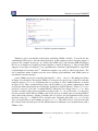
This section describes the tool support available if you wish to start model construction using UML
class diagrams. The AlarmInitUML.uml file can be found on the book’s web site7 . This UML
class diagram model is identical to the initial class diagram from the previous chapter except that
the Plant class has been updated with the three operations identified in Appendix A. Note that
the operations have not yet been given signatures. Download this .uml file and import it using
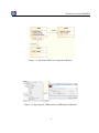
Modelio. When this model is open, the class diagram should look like that shown in Figure 3.1.
The small ‘+’ next to the rôle name schedule indicates that this association is public. The
‘-’ in front of the rôle name alarms indicates that it is private. You can change the visibility of
the schedule association to private by selecting the association and changing the Visibility with
the To:Expert.
You can update the signatures for the operations in the Plant class. However, this is awkward
and most developers prefer to use a text editor to perform such updates in the VDM++ text, then
converting back to the UML model automatically.
To convert a UML class diagram model to a VDM++ model, you first need to export the UML
model from Modelio to the Eclipse XMI format, called UML using the EMF UML3.0.0 format (see
Figure 3.2). This is then subsequently imported into Overture as will be explained in Section 3.6.
3.4
Using the Overture Perspective
Eclipse is an open source platform based on a workbench that provides a common look and feel
to a large collection of extension products. Thus if a user is familiar with one Eclipse product,
it will generally be easy to start using a different product on the same workbench. The Eclipse
7
http://www.vdmbook.com/twiki/bin/viewfile/Main/BookExamples?rev=1;filename=
AlarmInitUML.uml.
3
Tutorial to Overture/VDM-RT
Figure 3.1: The initial UML class diagram in Modelio.
Figure 3.2: Exporting the UML model to XMI format in Modelio.
4
Chapter 3. Overture Tool Support for VDM++: an Introductory Guide
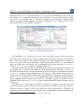
workbench consists of several panels known as views, such as the VDM Explorer view at the top
left of Figure 3.3. A particular collection of panels designed to assist a specific activity is called
a perspective. For example Figure 3.3 shows the standard Overture perspective which contains
views for managing Overture projects, viewing and editing files. As we shall see later, several
other perspectives are also available in Overture.
Figure 3.3: The Overture Perspective
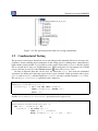
The VDM Explorer view allows you to create, select, and delete Overture projects and navigate
between the files in these projects. Start by importing the alarm project from zip file mentioned
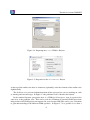
above. This can be done by right clicking the project view and selecting Import, followed by
General → Existing Projects into Workspace. In this way the projects from .zip file mentioned
above can be imported easily. Initially it is recommended that you only import the AlarmErrPP
and the Alarm++tracesPP projects as shown in Figure 3.48 .
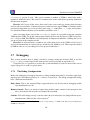
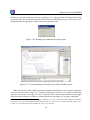
An editor customised to the dialect of VDM being used in the project will appear when one of
the imported files are selected in the Explorer view by double clicking. When the AlarmErrPP
project has been imported one can right click on the project in the Explorer view and then select the
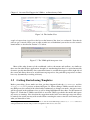
Properties item in the menu and then Figure 3.5 will pop up. This includes the properties set
for this project including specific VDM options. Note that there is a language version option that
for the AlarmErrPP project set to vdm10 which indicates that it include non-standard features
such as traces which is explained in Section 3.9. In addition, options are gathered here for
additional checks where the AlarmErrPP project simply follow the standard settings used for
new projects.
The Outline view, to the right of the editor (see Figure 3.6) displays an outline of the file
selected in the editor. It shows all declared classes, their instance variables, values, types, functions,
operations and traces. Figure 3.3 shows the outline view on the right hand side. Clicking on an
operation or a function will move the cursor in the editor to the definition of that operation/function.
8
You need both of these to carry out various exercises throughout this chapter.
5
Tutorial to Overture/VDM-RT
Figure 3.4: Importing the Alarm VDM++ Projects
Figure 3.5: Properties for the AlarmErrPP Project
At the top of the outline view there is a button to (optionally) order the elements of the outline view
alphabetically.
The Problems view presents information about all the open projects you are working on, such
as warning and error messages. In Figure 3.3 the problems view is shown at the bottom.
In the standard Overture perspective there is a VDM Quick Interpreter view in a pane in the
same area as the problems view. This can be used for evaluation of standard VDM expressions
independent of all VDM projects incorporated in your Overture IDE. This can be very convenient
to gain understanding of the different VDM operators. In Figure 3.7 it is possible to see how a
6
Chapter 3. Overture Tool Support for VDM++: an Introductory Guide
Figure 3.6: The Outline View
couple of expressions (typed in at the box at the botton of the view) are evaluated9 . Note that in
order to get a console where you are able to make use of definitions you need to use the console
launch mode as described in Section 3.7.1 below.
Figure 3.7: The VDM quick interpreter view
Most of the other features of the workbench, such as the menus and toolbars, are similar to
those used in other Eclipse applications, though it is worth noting that there is a special menu with
Overture-specific functionality. One convenient feature is a toolbar that appears on the right side of
the screen and allows the user to switch between perspectives; the particular perspectives on show
here vary dynamically according to history.
3.5
Getting Started using Templates
Before proceeding, please make sure that you have imported both the AlarmErrPP and the
Alarm++tracesPP projects as shown in Figure 3.4. When editing a VDM++ model, the Overture IDE parses the content of the editor buffer continuously as changes are made. Any parse errors
will be reported in the problems view, as well as being highlighted in the editor. See the bottom of
Figure 3.3. Each time a VDM++ model file is saved the editor type-checks the model and reports
any errors or warnings. Note also that the suggestions made in the error messages may not always
be entirely the action you may wish to take when correcting the source since the tool cannot guess
what you intended to write.
9
If errors appear in this evaluation the current version of the Overture IDE simply yield a Fatal error where it is
anticipated that later releases will provide more helpful run-time errors to the users.
7
Tutorial to Overture/VDM-RT
Figure 3.8: Explicit operation template
Templates can be particularly useful when modifying VDM++ models. If you hit the key
combination CTRL+space after the initial characters of the template needed, Overture triggers a
proposal. For example, if you type ”op” followed by CTRL+space, the Overture IDE will propose
the use of an implicit or explicit operation template as shown in Figure 3.8. The Overture IDE
supports several types of template: cases, quantifications, functions (explicit/implicit), operations
(explicit/implicit) and many more10 . Additional templates can easily be added in the future. The
use of templates makes it much easier for users lacking deep familiarity with VDM syntax to
nevertheless construct models.
A new VDM++ project is created by choosing File → New → Project. The dialog box shown
in Figure 3.9 will appear. Ensure that VDM++ is selected as the project type, click Next and then
name the project AlarmUML. Following this it is possible to select standard libraries as shown
in Figure 3.10. These standard libraries gives the possibility to get standard input/output, math
and general utility functionality by selecting the appropriate standard libraries. In this AlarmUML
project we can try to select the IO standard library. Afterwards one simply select Finish. Now
you have an almost empty project (with the exception of the IO.vdmpp file in the lib directory)
and you can then either add new VDM++ files to the project or simply paste in existing VDM++
source files from elsewhere. Adding a VDM++ file to a project you can rightclick on the project
and then select New → VDM-PP Class and then give a meaning full name (e.g. Test) to the
class you would like to start defining and press Finish. This will create a new class file with
the selected name and with space for the different kinds of definitions you can make inside such a
VDM++ class.
10
It is possible to see and enhance the complete list of these by selecting Window → Preferences → VDM → Templates.
8
Chapter 3. Overture Tool Support for VDM++: an Introductory Guide
Figure 3.9: Creating a New VDM++ Project
Figure 3.10: The VDM++ Standard Libraries
3.6
Mapping Between UML and VDM
In order to map the UML class diagram created in Modelio to VDM, use a new project inside
the VDM Explorer. Paste the UML file exported from Modelio into this new project. By rightclicking on the XMI/UML file in the VDM Explorer view, the UML Transformation can be chosen,
followed by Convert to VDM. This will create a new uml import directory with one vdmpp file
per class from the UML model. The round-trip engineering abilities of this link however is still at
a prototype stage so if you wish to use this you have to expect that this part is still not as automatic
as we would like.
The three classes from the Alarm system will be converted to VDM++ format (.vdmpp), one
file per class.
Before proceeding, delete the AlarmUML project in the Overture IDE. For the following, the
9
Tutorial to Overture/VDM-RT
AlarmErrPP project is used. This project contains a number of VDM++ model files with a
number of deliberate errors. The errors are common ones such a semicolons separating definitions
that has been forgotten.
Exercise 3.1 Correct all the errors discovered by the syntax and type checker from Overture
and save the corrected files. Continue this process until no errors appear. Hint: Consult the model
presented in Appendix A to see how values (note using “=” rather than “:=”), types and constructors should be defined and how access modifiers should be used. 2
After correcting all the errors in the AlarmErrPP project, it is possible to map the complete
VDM model to UML. To do this, simply right click the project root and choose UML Transformation → Export XMI. The XMI file can subsequently be imported in Modelio, enabling the user to
get an overview of the complete model.
Exercise 3.2 Add an instance variable to one of the other classes at the VDM++ level. Save it
and it will automatically be syntax and type checked at the VDM++ level. Then export the model
to XMI in order to see your changes in a new project in Modelio. 2
3.7
Debugging
This section describes how to debug a model by testing it using the Overture IDE. A test file
(Test1.vdmpp) can be found in the alarm project and it is provided in Appendix A.2.
Using this test, it is possible to exercise the system informally in order to check if the correct
expert is paged as a result of a given alarm.
3.7.1
The Debug Configuration
Before the debugging can begin in Overture, a debug configuration must be created by right clicking the project and choosing Debug As → Debug configuration. The debug configuration dialog
have 3 different launch modes:
Entry Point: This is the standard Eclipse approach where one decides before debugging which
operation/function to call.
Remote Console: This is an anvanced option that enables remote control of the interpreter and
this is described in the Overture user manual [Larsen&10].
Console: This will simply start up a console where the user interactive can debug different operations/functions defined in the selected project11 .
11
For VDMTools users this will be a familiar console corresponding to a VDM model that has been initialised in
VDMTools’ interpreter.
10
Chapter 3. Overture Tool Support for VDM++: an Introductory Guide
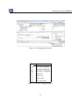
Here we will start with using the traditional Eclipse approach with an “Entry Point” launch
configuration which requires the project name and the class and the operation/function used as the
entry point of the test. Figure 3.11 shows the debug configuration for the alarm model. The class
and operation/function name can be chosen from a Browse dialog; if the operation or function has
arguments, these must be typed in manually between the brackets of the entry point function/operation.
Figure 3.11: The debug configuration dialog
Once the debug configuration is ready, the model can be debugged. If any breakpoints are set
this will change the main perspective of the Overture IDE to the Debug perspective which contains
the views needed for debugging in VDM. The Debug perspective is illustrated in Figure 3.12.
Breakpoints can easily be set by double clicking in left margin in the editor view. When the
debugger reaches the location of a breakpoint, evaluation suspends and you can inspect the values
of different variables and step through the VDM model line by line.
3.7.2
The Debug Perspective
The Debug view in the upper left corner of the Debug perspective shows all running threads in the
VDM++ model and their call stacks. It also shows whether a given model is stopped, suspended
or running. All threads are also shown, along with their running status. It is possible to switch
between threads from the Debug view.
At the top of the view are buttons for controlling debugging such as stop, step into, step over
and resume. These are standard Eclipse debugging buttons (see Table 3.1).
11
Tutorial to Overture/VDM-RT
Figure 3.12: Debugging perspective
Button Explanation
Resume debugging
Suspend debugging
Terminate debugging
Step into
Step over
Step return
Use step filters
Table 3.1: Overture debugging buttons
12
Chapter 3. Overture Tool Support for VDM++: an Introductory Guide
The Variables view shows all the variables in a given context, when a breakpoint is reached.
The variables and their displayed values are automatically updated when stepping through a model.
The view is located in the upper right corner in the Debug perspective.
Figure 3.13: Breakpoint View
3.7.3
Breakpoints
The Breakpoints view gives an overview of all breakpoints set (see Figure 3.13). From this view
you can easily navigate to the location of a given breakpoint, disable or delete them, or set their
properties. Conditional breakpoints are also supported. These are a powerful tool for the developer
since they allow a condition to be specified which has to be true in order for the debugger to stop
at the given breakpoint. The condition can either be a boolean expression using variables in scope
at the breakpoint, or it can be a hit count after which the breakpoint should become active.
Figure 3.14: Conditional breakpoint options
You can make a simple breakpoint conditional by right clicking on the breakpoint mark in the
left margin of the editor and selecting the option Breakpoint properties. This opens a dialog shown
13
Tutorial to Overture/VDM-RT
in Figure 3.14.
The Expressions view allows the user to enter watch expressions whose values are automatically displayed and updated when stepping. Watch expressions can be added manually or created
by selecting create watch expression from the Variables view. It is possible to edit existing expressions. Like the Breakpoints view, this view is hidden in the upper right hand corner in Figure 3.12.
Exercise 3.3 Use the interpreter to evaluate the following expression: new Test1().Run().
2
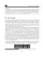
3.8
Test coverage
It is often useful to know how much of a model has been exercised by a set of tests12 . This gives
some insight into the thoroughness of a test suite and may also help to identify parts of the model
that have not been assessed, allowing new tests to be devised to cover these. When any evaluation
is performed on a VDM++ model, the interpreter records the lines of the VDM++ model that are
executed. This permits the line coverage to be examined after a test to identify the parts of the
VDM++ model that have not yet been exercised – coverage is cumulative, so a set of tests can be
executed and their total coverage examined at the end.
In our simple example, the different tests in the exercise above does cause the majority of the
VDM++ model to be executed, but for demonstration purposes let us start by cleaning the model
(right click on the project and select Clean). If we simply take the AlarmPP debug launch
configuration the ExpertIsOnDuty and ExpertToPage operations in plant.vdmpp are
called by the Run function. Remember that whenever test coverage information is desired the
Generate Coverage option must be selected as shown in Figure 3.1113 . Once the debugger
has completed and the result is written out in the console it is possible to right click on the
AlarmPP project and select the Latex → Latex coverage. The coverage information that have
been gathered in any expressions that have been debugged since the last change to a file have been
saved or the project have been cleaned will be turned into a pdf file. The AlarmPP.pdf file is
placed in the generated/latex directory as shown in Figure 3.15 and it includes the VDM
definitions from all the files included in the project including coverage information. Note that
whenever the model is adjusted or it is cleaned so it gets type checked again all the files in the
generated directory are deleted.
The coverage information is provided in a way where uncovered expressions are shown in
red in the generated pdf file. In addition to the content of each VDM++ source file a table with
coverage overview is provided in tabular form. For the plant.vdmpp file this looks like:
Function or operation Coverage Calls
ExpertIsOnDuty
100.0%
1
ExpertToPage
100.0%
1
12
13
Note that this feature is not yet supported for models using unicode characters such a Japanese identifiers.
Note that using this feature required pdflatex to be installed.
14
Chapter 3. Overture Tool Support for VDM++: an Introductory Guide
NumberOfExperts
Plant
PlantInv
plant.vdmpp
0.0%
100.0%
100.0%
89.0%
0
1
2
5
where the ExpertIsOnDuty and ExpertToPage operations are fully covered by just one call
(due to the fact that its body is simply one line) whereas the PlantInv operation is called twice.
Exercise 3.4? Before reading on try to add two new operations to the Plant class called
AddExpertToSchedule and RemoveExpertFromSchedule respectively for adding and
removing an expert to/from the schedule for a paticular period. Please remmebr to include preconditions when necessary. 2
15
Tutorial to Overture/VDM-RT
Figure 3.15: The generated pdf file with test coverage information
3.9
Combinatorial Testing
The previous sections have shown how to test and debug models manually. However, Overture also
contains a feature enabling more automation in the testing process, making more comprehensive
high-volume testing feasible. It is possible to write regular expressions, as traces, that one would
like to expand into a large set of individual tests. When new traces are incorporated in a VDM
project you may need to press the Refresh button ( ) in the CT Overview view.
In order to illustrate how this can be used, we extend the Plant class with two additional
operations for adding and removing experts from a given schedule. Both operations take a given
Period and an Expert and then update the schedule instance variable from the Plant class.
The AddExpertToSchedule operation can be defined as:
public AddExpertToSchedule: Period * Expert ==> ()
AddExpertToSchedule(p,ex) ==
schedule(p) := if p in set dom schedule
then schedule(p) union {ex}
else {ex};
and the RemoveExpertFromSchedule operation can be expressed as:
public RemoveExpertFromSchedule: Period * Expert ==> ()
RemoveExpertFromSchedule(p,ex) ==
let exs = schedule(p) in
schedule := if card exs = 1
then {p} <-: schedule
else schedule ++ {p |-> exs \ {ex}}
16
Chapter 3. Overture Tool Support for VDM++: an Introductory Guide
pre p in set dom schedule;
Note that RemoveExpertFromSchedule contains a deliberate error. It fails to take account
of the invariant so the operation can leave the Plant in a state where it cannot be guaranteed
that experts with the right qualifications are available in the periods that have been scheduled.
AddExpertToSchedule has a similar error. If nobody is scheduled at the period provided as
an argument, and the expert added for the schedule at this period does not have all the necessary
qualifications, the invariant will again be violated. In fact this means that one would probably have
to change the signature of this operation such that it instead of taking a simple expert would take a
collection of experts. Instead of adding the two operations manually, use the Alarm++tracesPP
project.
We could use the debugger presented above to test these two new operations manually, but we
can also automate a part of this process. In order to do the automation, Overture needs to know
about the combinations of operation calls that you would like to have carried out, so it is necessary
to write a kind of regular expression called a trace. VDM++ has been extended such that traces
can be written directly as a part of a VDM++ model. In our case, inside the Test1 class one can
write:
traces
AddingAndDeleting:
let myex in set exs
in
let myex2 in set exs \ {myex}
in
let p in set ps
in
(plant.AddExpertToSchedule(p,myex);
plant.AddExpertToSchedule(p,myex2);
plant.RemoveExpertFromSchedule(p,myex);
plant.RemoveExpertFromSchedule(p,myex2));
The three nested let-be statements in the trace called AddingAndDeleting yield all possible
combinations of their variable bindings whereas manual debugging will just select a few combinations. The cardinality of these sets determines the overall number of test cases, each being formed
as a sequence of four operation calls, as shown. In this case, the cardinality of the three sets are
respectively 4, 3 and 4. Multiplying these gives 48 tests in total. If you select the Combinatorial
Testing perspective you will see the CT Overview view. Inside this combinatorial testing view you
can select the Alarm++tracesPP project, right click it and choose the Full Evaluation option
as shown in Figure 3.16. Now Overture expands and executes all 48 test cases one after another.
The results of these executions are illustrated with green check marks and red crosses, meaning
17
Tutorial to Overture/VDM-RT
that the tests passed or failed respectively (see Figure 3.17). Note that in the Combinatorial Testing
perspective, the view in the lower region is able to show the individual steps of a selected test case,
along with the corresponding results from its four operation calls.
Figure 3.16: Invoking the combinatorial testing feature
Figure 3.17: Using Combinatorial Testing for the Alarm VDM++ model
The syntax for traces also enables operation repetition and alternatives to be specified, but these
were not needed for this simple case. Using the full power of traces, it is possible to efficiently
generate and execute very large test suites. Naturally, this is most likely to find inconsistencies
when the model attempts to define its essential predicates (invariants, pre and post-conditions)14 .
14
Note that when using repetitions and sequencing in combination it is easy to define traces that expands to hundreds of
thousands of test cases and naturally their execution may then be very slow if one executes them all. Thus it is also
possible to use a feature that reduce the numbers of tests to be executed.
18
Chapter 3. Overture Tool Support for VDM++: an Introductory Guide
3.10
Proof Obligations
The Overture tool is also able to generate Proof Obligations automatically for VDM++ models.
Proof obligations are boolean expressions that describe constraints to be met at various points in
the model in order to ensure that the model is internally consistent (i.e. no run-time errors will
occur while debugging if these are all satisfied). Proof obligations are generated to ensure, for
example, that operations will always respect invariants on instance variables. Each proof obligation
generated from a model should evaluate to true.
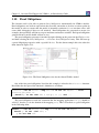
The proof obligation generator is invoked by right clicking on the project in the Explorer view
and then selecting the Proof Obligations -> Generate Proof Obligations entry. This will start up
a proof obligation perspective with a special PO view. For the alarm example this view takes the
form shown in Figure 3.18.
Figure 3.18: The Proof Obligation view for the Alarm VDM++ model
One of the first proof obligations listed for this example is related to the PlantInv function.
Recall that the first part of the function’s definition is as follows:
PlantInv: set of Alarm * map Period to set of Expert -> bool
PlantInv(as,sch) ==
(forall p in set dom sch & sch(p) <> {}) and ...
The proof obligation records the constraint that the mapping application sch(p) should be
valid (i.e. that the p is in the domain of the mapping sch). This is described as a proof obligation
in the following form:
forall as:set of Alarm, sch:map Period to set of Expert &
forall p in set (dom sch) &
p in set dom sch
19
Tutorial to Overture/VDM-RT
It is easy to see with simple pattern matching that this proof obligation is true and thus in the Proof
Obligation Explorer view the status field the small checkmark indicates that indeed the proof
obligation generation have been able to automatically determine this.
In general proof obligations represent checks that should be made on a model in order to gain
confidence in its consistency. At present, proof obligations have to be checked by manual inspection of the model code. Proof tools are being developed for Overture to check as many as possible
of the proof obligations automatically and with human assistance, but there are always likely to
be some that have to be checked manually. If we for example instead consider the fifth proof
obligation it is derived from the body of the expertToPage operation. That body looks like:
let expert in set schedule(p) be st
a.GetReqQuali() in set expert.GetQuali()
in
return expert
where an expert on duty with the right qualifications are being selected. The proof obligation here
states:
exists expert in set schedule(p) &
a.GetReqQuali() in set expert.GetQuali()
This is exactly describing that in order for this expression to be defined it is necessary to gurantee
that there exists at least one such expert. Thus, without taking the pre-condition for the operation
here into account it would not be possible to gurantee that. So it will never be possible to automatically to determin this using simple pattern matching because this is only guranteed because of the
invariant over the instance variables for the Plant class that has been defined.
3.11
A Command-Line Interface
So far only the graphical user interface of Overture has been presented but the core of Overture
also provides a simple command line interface. This is useful for the automatic batch execution
of tests, though the command line also provides a full set of interactive execution and debugging
commands which can be useful when examining batch tests.
Overture is written in Java, and so to run it from the command line, the Overture jar file15
should be executed with a Java JRE (version 7 or later):
java -jar Overture-2.0.0.jar
15
See the Overture documentation at sourceforge.net/projects/overture for the location of the jar file or
use the script or windows bat file incorporating this.
20
Chapter 3. Overture Tool Support for VDM++: an Introductory Guide
If the jar file is executed with no further options like this, it will print a list of available options
and exit. The most important option is the VDM dialect that the tool should use. In the case of
our alarm example, we want to use VDM++ for which the option is -vdmpp. After this, we can
simply specify the names of the VDM model files to load, or the name of a directory from which
all VDM model files will be loaded:
java -jar Overture-2.0.0.jar -vdmpp AlarmPP
That will perform a syntax and type check of all the VDM model files in the AlarmPP directory,
producing any errors and warning messages on the console, before terminating:
Parsed 4 classes in 0.109 secs. No syntax errors
Type checked 4 classes in 0.093 secs. No type errors
In the case of our alarm example, there are no syntax or type checking errors. Any warnings can
be suppressed using the -w option.
If a VDM model has no type checking errors, it can either be given an expression to evaluate as
an option on the command line, or the user can enter an interactive mode to evaluate expressions
and debug their execution.
To evaluate an expression from the command line, the -e option is used, followed by a VDM
expression to evaluate. You may also find the -q option useful, as this suppresses the informational
messages about the parsing and type checking:
java -jar Overture-2.0.0.jar -vdmpp -q -e "new Test1().Run()"
AlarmPP
This produces a single line of output for the evaluation, since the parsing and checking messages
are suppressed:
mk_({mk_token("Monday day")},
Expert{#3, quali:={<Mech>, <Bio>}})
Clearly a batch of test evaluations could be performed automatically by running a series of
similar commands and saving the output results for comparison against expected results.
To run the command line interpreter interactively, the -i command line option must be given.
Instead of terminating after the type check, this will cause VDMJ to enter its interactive mode, and
give the interactive > prompt:
Type checked 4 classes in 0.078 secs. No type errors
Initialized 4 classes in 0.063 secs.
Interpreter started
21
Tutorial to Overture/VDM-RT
>
From this prompt, various interactive commands can be given to evaluate expressions, debug their
evaluation, or examine the VDM model environment. The help command lists the commands
available. The quit command leaves the interpreter.
For example, the following session illustrates the creation of a test object, followed by an
evaluation (using a print command) of its Run operation, and a debug session with a breakpoint
at the start of the same operation:
> create test := new Test1()
> print test.Run()
= mk_({mk_token("Monday day")},
Expert{#3, quali:={<Mech>, <Bio>}})
Executed in 0.15 secs.
> break Test1‘Run
Created break [1] in ’Test1’ (test1.vdmpp) at line 26:3
26:
let periods = plant.ExpertIsOnDuty(ex1),
> print test.Run()
Stopped break [1] in ’Test1’ (test1.vdmpp) at line 26:3
26:
let periods = plant.ExpertIsOnDuty(ex1),
[MainThread-10]> print plant.NumberOfExperts(
mk_token("Wednesday"))
Runtime: Error 4071: Precondition failure:
pre_NumberOfExperts in
’Test1’ (console) at line 1:1
[MainThread-10]> continue
= mk_({mk_token("Monday day")}
Expert{#3, quali:={<Mech>, <Bio>}})
Executed in 72.651 secs.
Notice that the print command is available at the breakpoint to examine the runtime state of the
system. In the example, we attempt to evaluate an operation which fails its precondition (because
the system is not yet initialized). The help command is context sensitive, and will list the extra
debugging commands available at a breakpoint, such as continue, step, stack, list and so
on. The full set of commands is described in the Overture User Guide16 .
16
Supplied with the Overture documentation.
22
Chapter 3. Overture Tool Support for VDM++: an Introductory Guide
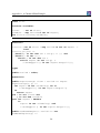
3.12
Summary
In this guide we have introduced the following major features of tool support for VDM++:
• using Modelio with class diagrams;
• mapping back and forth between Modelio and Overture;
• syntax checking of VDM++ models;
• type checking of VDM++ models;
• executing and debugging VDM++ models;
• collecting and displaying test coverage information on VDM++ models;
• a command-line interface;
• combinatorial testing enabling automation of parts of the testing process;
• proof obligation generation and
• a command-line interface.
23
Tutorial to Overture/VDM-RT
24
References
[Fitzgerald&98]
John Fitzgerald and Peter Gorm Larsen. Modelling Systems – Practical Tools
and Techniques in Software Development. Cambridge University Press, 1998.
[Larsen&10]
Peter Gorm Larsen and Kenneth Lausdahl and Augusto Ribeiro and Sune
Wolff and Nick Battle. Overture VDM-10 Tool Support: User Guide. Technical Report TR-2010-02, The Overture Initiative, www.overturetool.org, May
2010. 103 pages.
25
Tutorial to Overture/VDM-RT
26
Appendix A
A Chemical Plant Example
This appendix presents the requirements for a simple alarm system for a chemical plant. It forms
a running example that serves to illustrate the process described earlier and to introduce elements
of the VDM++ modelling language. Although the modelling process is described here as though
it were a single-pass activity, a real development would usually be iterative.
A.1
An informal description
The example is inspired by a subcomponent of a large alarm system developed by IFAD A/S and
introduced in [Fitzgerald&98]. A model of the system will be developed and validated using the
facilities of Enterprise Architect and Overture enabling a graphical overview of the model in the
form of UML class diagrams and sequence diagrams corresponding to traces. Chapter 3 provides
an interactive and hands-on tour of the tools available for supporting the development of the model.
Imagine that you are developing a system that manages the calling out of experts to deal with
operational faults discovered in a chemical plant. The plant is equipped with sensors that are able
to raise alarms in response to conditions in the plant. When an alarm is raised, an expert must be
called to the scene. Experts have different qualifications for coping with different kinds of alarms.
It has been decided to produce a model to ensure that the rules concerning the duty schedule and
the calling out of experts are correctly understood and implemented. The individual requirements
are labelled R1, R8 for further reference:
R1. A computer-based system is to be developed to manage the alarms of this plant.
R2. Four kinds of qualifications are needed to cope with the alarms: electrical, mechanical,
biological, and chemical.
R3. There must be experts on duty during all periods allocated in the system.
R4. Each expert can have a list of qualifications.
R5. Each alarm reported to the system has a qualification associated with it along with a description of the alarm that can be understood by the expert.
27
Tutorial to Overture/VDM-RT
R6. Whenever an alarm is received by the system an expert with the right qualification should be
found so that he or she can be paged.
R7. The experts should be able to use the system database to check when they will be on duty.
R8. It must be possible to assess the number of experts on duty.
In the next section the development of a model of an alarm system to meet these requirements
is initiated. The purpose of the model is to clarify the rules governing the duty roster and calling
out of experts to deal with alarms.
A.2
A VDM++ model of the Alarm example
This section presents the UML class diagram and the full VDM++ model of the alarm example.
However, it does so without any explanatory text. That is placed in the VDM++ book so if you are
a newcommer to VDM++ please read that there.
A.2.1
A UML Class Diagram
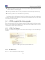
In Figure A.1 the final class diagram for the extended alarm example is shown from Enterprise
Architect.
Figure A.1: UML diagram translated from VDM++ files
A.2.2
The Plant Class
The Plant class is the main class in this example.
28
Appendix A. A Chemical Plant Example
class Plant
instance variables
alarms
: set of Alarm;
schedule : map Period to set of Expert;
inv PlantInv(alarms,schedule);
functions
PlantInv: set of Alarm * map Period to set of Expert ->
bool
PlantInv(as,sch) ==
(forall p in set dom sch & sch(p) <> {}) and
(forall a in set as &
forall p in set dom sch &
exists expert in set sch(p) &
a.GetReqQuali() in set expert.GetQuali());
types
public Period = token;
operations
public ExpertToPage: Alarm * Period ==> Expert
ExpertToPage(a, p) ==
let expert in set schedule(p) be st
a.GetReqQuali() in set expert.GetQuali()
in
return expert
pre a in set alarms and
p in set dom schedule
post let expert = RESULT
in
expert in set schedule(p) and
a.GetReqQuali() in set expert.GetQuali();
public NumberOfExperts: Period ==> nat
NumberOfExperts(p) ==
29
Tutorial to Overture/VDM-RT
return card schedule(p)
pre p in set dom schedule;
public ExpertIsOnDuty: Expert ==> set of Period
ExpertIsOnDuty(ex) ==
return {p | p in set dom schedule &
ex in set schedule(p)};
public Plant: set of Alarm *
map Period to set of Expert ==> Plant
Plant(als,sch) ==
( alarms := als;
schedule := sch)
pre PlantInv(als,sch);
end Plant
A.2.3
The Expert Class
class Expert
instance variables
quali : set of Qualification;
types
public Qualification = <Mech> | <Chem> | <Bio> | <Elec>;
operations
public Expert: set of Qualification ==> Expert
Expert(qs) ==
quali := qs;
public GetQuali: () ==> set of Qualification
GetQuali() ==
return quali;
end Expert
30
Appendix A. A Chemical Plant Example
A.2.4
the Alarm Class
class Alarm
types
public String = seq of char;
instance variables
descr
: String;
reqQuali : Expert‘Qualification;
operations
public Alarm: Expert‘Qualification * String ==> Alarm
Alarm(quali,str) ==
( descr := str;
reqQuali := quali
);
public GetReqQuali: () ==> Expert‘Qualification
GetReqQuali() ==
return reqQuali;
end Alarm
A.2.5
A Test Class
class Test1
instance variables
a1
a2
: Alarm
: Alarm
:= new Alarm(<Mech>,"Mechanical fault");
:= new Alarm(<Chem>,"Tank overflow");
31
Tutorial to Overture/VDM-RT
ex1 :
ex2 :
ex3 :
ex4 :
plant:
Expert
Expert
Expert
Expert
Plant
:=
:=
:=
:=
:=
new
new
new
new
new
Expert({<Mech>,<Bio>});
Expert({<Elec>});
Expert({<Chem>,<Bio>,<Mech>});
Expert({<Elec>,<Chem>});
Plant({a1},{p1 |-> {ex1,ex4},
p2 |-> {ex2,ex3}});
values
p1:
p2:
p3:
p4:
Plant‘Period
Plant‘Period
Plant‘Period
Plant‘Period
=
=
=
=
mk_token("Monday day");
mk_token("Monday night");
mk_token("Tuesday day");
mk_token("Tuesday night");
operations
public Run: () ==> set of Plant‘Period * Expert
Run() ==
let periods = plant.ExpertIsOnDuty(ex1),
expert = plant.ExpertToPage(a1,p1)
in
return mk_(periods,expert);
end Test1
32