1
Robo-Erectus
Virtual Simulator Software
RE–VSS – CSR
User Manual
Version 1
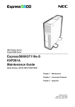
TO CREATE A LEARNING ENVIRONMENT FOR TODAY,
AND TO FOSTER UNDERSTANDING AMONG HUMANS
AND TECHNOLOGY FOR TOMORROW
RoboErectus Virtual Simulator Software RE – VSS – CSR User Guide
2
Copyright Warning
©2011 Robo-Erectus. All rights reserved.
No part of this training material may be reproduced, stored in a retrieval system or
transmitted, in any form or by any means, electronic, mechanical, photocopying, recording or
otherwise, without the prior permission of the copyright owner.
RoboErectus Virtual Simulator Software RE – VSS – CSR User Guide
3
Contents
1.
Introduction ..................................................................................................................... 6
2.
Microsoft Robotics Developer Studio (MRDS) and Robo-Erectus Virtual Simulator
Software for CoSpace Rescue ........................................................................................ 7
3.
Visual Simulated Environment ....................................................................................... 8
4.
CoSpace Virtual Robot ................................................................................................... 9
5.
3D Virtual Environment .............................................................................................. 10
6.
RE-VSS-CSR Control Panel ....................................................................................... 11
6.1
The Robot Control Panel .............................................................................................. 11
6.2
Competition Control Panel ........................................................................................... 16
7.
AI Development Panel .................................................................................................. 20
7.1
Introduction of AI Development Environment ............................................................ 20
7.2
Project Management Section ........................................................................................ 21
7.3
Statement Management Section ................................................................................... 25
7.4
Programming Section ................................................................................................... 33
7.5
C++ Programming Interface ......................................................................................... 43
8.
Practical Guide .............................................................................................................. 49
8.1
Manual control of robot ................................................................................................ 49
8.2
Working with ultrasonic sensors .................................................................................. 50
8.3
Working with compass sensors .................................................................................... 56
8.4
Working with colour sensors ........................................................................................ 63
9.
MPLAB IDE, MPLAB C30 and PICkit 2 for PIC Microcontroller ............................. 67
9.1
Get Ready ..................................................................................................................... 67
RoboErectus Virtual Simulator Software RE – VSS – CSR User Guide
4
9.2
Installation .................................................................................................................... 68
9.3
Running MPLAB IDE .................................................................................................. 69
9.4
PICkit 2 Programming Interface .................................................................................. 74
10.
Working with Real Robots............................................................................................ 76
10.1 Install ZigBee Modules ................................................................................................ 76
10.2 Manual Control of Real Robots.................................................................................... 76
10.3 Fully Autonomous Robot ............................................................................................. 77
Appendix A. User Guide of Virtual Simulation Environment .............................................. 83
A1. Starting Visual Simulation Environment...................................................................... 83
A2. Visual Simulation Environment Menus ....................................................................... 84
A3. Visual Simulation Environment Keyboard and Mouse ................................................ 87
Appendix B. ZigBee Communication Module Setup ........................................................... 90
Appendix C. RE – VSS – CSR Directory Structure .............................................................. 93
Appendix D. How to Control the Real and Virtual Robots Using Your Own C Code ......... 95
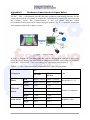
Appendix E. Hardware Connection for CoSpace Robot ....................................................... 96
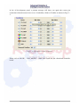
Appendix F. Communication Protocol ................................................................................. 98
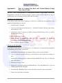
Appendix G. Action To Be Taken After the Treasures Found ............................................ 100
Contact Us … ....................................................................................................................... 101
RoboErectus Virtual Simulator Software RE – VSS – CSR User Guide
5
1.
Introduction
Popular interest in robotics has increased astonishingly in the last few years. Robotics is seen
by many as offering major new benefits in education at all levels. Is it a fashion? No. Robots
are excellent tools to train students‟ competency in both academic and workplace. Robotics in
Education can enhance their knowledge in science, mathematics, physics, mechanics, and
programming, as well as time management, project management, problem solving skills,
creativity, and teamwork. Many schools have their own robotics lab for extra curricula
activities, but most schools still lack the resources. Students may not be able to own a robot
all by themselves. If it can be shown that robotics has sustained potential in education, the
virtual robot and easy programming tool will give students an alternative platform for
learning in the area of robotics.
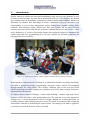
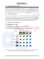
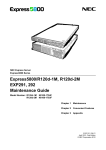
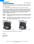
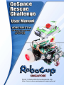
Fig. 1 – 1 : Students participating in RoboCupJunior CoSpace Rescue (Demo) Challenge
RoboCupJunior CoSpace Rescue Challenge is an educational initiative to promote knowledge
and skills in engineering design, programming, electronic control, and the 3D simulation
through robotics for young minds. The CoSpace Challenge aims to fuse real and virtual
robotic technologies towards bridging two prominent areas of the future namely, Interactive
Digital Media and Robotics.
In CoSpace Rescue (Demo) Challenge – treasure hunt challenge, a treasure map with a list of
treasures will be provided to each participating team. The team has to develop appropriate
strategies for a virtual autonomous robot to navigate through the treacherous terrain by
avoiding obstacles and collecting treasures in the 3D virtual environment while competing
with another robot that is performing the same mission. The strategies will then be applied to
a real robot to search the treasures in the real world.
RoboErectus Virtual Simulator Software RE – VSS – CSR User Guide
6
2.
Microsoft Robotics Developer Studio (MRDS) and Robo-Erectus
Virtual Simulator Software for CoSpace Rescue
Microsoft Robotics Developer Studio (MRDS) is a development platform for the robotics
community, supporting a wide variety of users, hardware, and application scenarios. MRDS
is not a tool to program code that will execute directly on the microcontroller of a robot.
Instead, researchers and scientists can use MRDS to develop a user friendly graphical
interactive programming interface and virtual environment for their own robots. Students
without programming experience can then use the programming interface and virtual
environment developed to program and control both real and virtual robots. The high
resolution visual simulation environment that integrates 3D software physics supplied by the
Ageia Technologies PhysX engine let students have an actual virtual 3D or CoSpace
experience.
The virtual robot and the user friendly interactive programming interface – the Virtual
Simulator Software for CoSpace Rescue, RE–VSS–CSR, is developed by the Advanced
Robotics and Intelligent Control Centre (ARICC), a Technology & Innovation Centre in
Singapore Polytechnic. This educational package is powered by Microsoft® Robotics
Developer Studio. It gives users an opportunity to work with both virtual and real robots. The
RE–VSS–CSR platform provides a venue for users to understand the physical structure,
sensors, motors, and the programming of a robot. Students will be able to program a robot to
perform its mission in both real and virtual environment using this educational package.
The RE–VSS–CSR offers hands on technological experience to motivate young minds to
learn and share knowledge with fellow participants. It also helps in the social and emotional
development of the students as they work together in groups and build inter-personal skills
required for their successful future in the real world.
RoboErectus Virtual Simulator Software RE – VSS – CSR User Guide
7
3.
Visual Simulated Environment
The Visual Simulation Environment (VSE) simulates physical objects and their interactions
including collisions, friction and gravity. To launch the RE–VSS–CSR, you need to double
click the icon “
” on desktop. Fig. 3 – 1 shows the Visual Simulation Environment*
(VSE) for CoSpace Rescue. It consists of many virtual entities, such as virtual robots, a
rescue arena, ground, sky, sun, and camera (invisible), etc.
Fig. 3-1: Microsoft visual simulation environment
When the simulator is running in the Visual Simulation Environment, you can move the
camera viewpoint by dragging the mouse pointer across the screen. It does not change the
camera position but it changes the point that the camera is looking at.
* You will need to fill up a registration form in order to launch the VSE.
The quick user guide for the Virtual Simulation Environment is attached in Appendix A.
RoboErectus Virtual Simulator Software RE – VSS – CSR User Guide
8
4.
CoSpace Virtual Robot
The platform supports all types of real robots equipped with the RE-controller board. It can
be integrated with Lego brick, Vex components, and other commercial sensors, servos, and
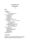
motors. The CoSpace virtual robot RE-VWheelie02 is equipped with 4 ultrasonic sensors, 2
colour sensors, and 1 compass sensor as shown in Fig. 4 – 1. They are used to detect
obstacles/boundaries, colour objects and direction.
Left Ultrasonic Sensor
Front Ultrasonic Sensor
Right Ultrasonic Sensor
Back Ultrasonic Sensor
Compass Sensor
Left Colour Sensor
Right Colour Sensor
Fig. 4 – 1: CoSpace virtual Robot RE-VWheelie02
RoboErectus Virtual Simulator Software RE – VSS – CSR User Guide
9
5.
3D Virtual Environment
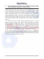
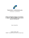
Fig. 5 – 1 shows the 3D virtual environment for the CoSpace Rescue Challenge. It consists of
two virtual robots, some obstacles, and a set of different coloured objects. The information
centre displays the current date and time, the team name, and the score.
Information Board
Virtual Robot
Virtual Object
Obstacles
Fig. 5 – 1: RE–VSS–CSR 3D virtual environment
Obstacles
The obstacles are 10cm in height.
Virtual Objects
There are two types of objects – red objects and black objects.
Virtual Robots
Two virtual robots, red robot and blue robot are used to represent two teams.
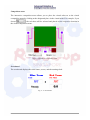
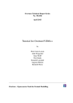
Information Board
The Information board shows the team name, score, etc
Team name
Total score
Points for the treasures on the cart
Treasures on the cart
Fig. 5 – 2: Information Board
RoboErectus Virtual Simulator Software RE – VSS – CSR User Guide
10
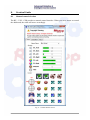
6.
RE-VSS-CSR Control Panel
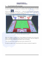
Fig. 6 – 1 shows the RE–VSS–CSR control panel. The control panel consists of two subpanels, namely Robot Control Panel and Competition control Panel.
Fig. 6 – 1: RE–VSS–CSR control panel.
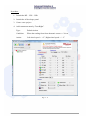
6.1
The Robot Control Panel
Fig. 6 – 2 shows the robot control panel. In this panel, you are able to
View the real-time sensor feedback of a selected robot;
Control real/virtual robot(s) via dashboard or game controller;
RoboErectus Virtual Simulator Software RE – VSS – CSR User Guide
11
Robot Selection
Real-time Sensor Feedback
Robot Control
Fig. 6 – 2: RE–VSS–CSR Robot Control Panel
RoboErectus Virtual Simulator Software RE – VSS – CSR User Guide
12
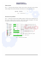
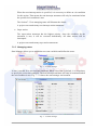
Robot selection
Fig. 6 – 3 shows the robot selection. It allows user to select a robot and view the real-time
sensor reading. The real robot will only be selected once it is connected to the server.
Fig. 6 – 3: Robot selection
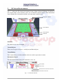
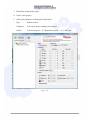
Real-time sensor feedback
Fig. 6 – 4 shows the real-time sensor feedback segment. It allows users to monitor the realtime sensor readings when the selected virtual robot navigates through the 3D virtual
environment, or the selected real robot moves in the real world.
Reading of front ultrasonic sensor, cm
Reading of back ultrasonic sensor, cm
Reading of left ultrasonic sensor, cm
Reading of right ultrasonic sensor, cm
Reading of left colour senor
Reading of right colour sensor
Reading of compass sensor, degree
Timer, second
Fig 6 – 4: Real-time sensor feedback
RoboErectus Virtual Simulator Software RE – VSS – CSR User Guide
13
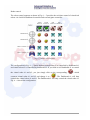
Robot control
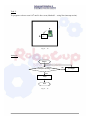
The robot control segment as shown in Fig. 6 – 5 provides the real-time control of virtual/real
robots via a build-in dashboard controller and external game controller.
Virtual
Robot #1
Virtual
Robot #2
Real
Real
Robot #1 Robot #2
Dashboard #1
Dashboard #2
Game Controller #1
Game Controller #2
Fig. 6 – 5: Robot control segment
The configuration in Fig. 6 – 5 shows that the virtual robot #1 is controlled by Dashboard #1
and virtual robot #2 is controlled by dashboard #2. If you wish to use Dashboard #1 to control
the virtual robot #1 and #2, you just simply click on the corresponding “
” which
connects virtual robot #1 and #2 and change it to “
”. The Dashboard #1 will then
controls the virtual robot #1 and #2. The Dashboard #2 will only control the virtual robot #2.
Fig. 6 – 6 shows the configuration.
RoboErectus Virtual Simulator Software RE – VSS – CSR User Guide
14
Fig. 6 – 6: Robot control configuration
Fig. 6 – 6 shows that the real robots and game controller are not connected. Session 10 shows
the procedure of connecting a real robot to the CoSpace server.
Dashboard and Game Controller
The dashboard and game controller are used to control both real and virtual robots movement
in their corresponding real world and 3D virtual environment. The sensor feedback segment
will display the real-time sensor reading during the robots navigation.
RoboErectus Virtual Simulator Software RE – VSS – CSR User Guide
15
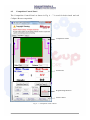
6.2
Competition Control Panel
The Competition Control Panel as shown in Fig. 6 – 7 is used for both virtual and real
CoSpace Rescue competition.
Competition Arena
Scoreboard
Programming Interface
Game Control
Fig. 6 – 7: Competition Control Panel
RoboErectus Virtual Simulator Software RE – VSS – CSR User Guide
16
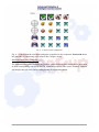
Competition arena
The interactive competition arena allows you to place the virtual robot on to the virtual
competition arena by clicking at the designated place in the virtual arena. For example, if you
choose
, the red robot will be selected and placed on the respective location in
the virtual competition arena.
Fig. 6 – 8: Interactive competition arena
Scoreboard
The scoreboard displays the team names, scores, and the running clock.
Fig. 6 – 9: Scoreboard
RoboErectus Virtual Simulator Software RE – VSS – CSR User Guide
17
Game control
The game control as shown in Fig. 6 – 10 provides the overall control of the competition. It
allows judges to load the AI strategies and run the game.
Fig. 6 – 10: The game control
Load Blue Team AI/Load Red Team AI – to load the AI strategy designated for Blue
Team or Red Team. The AI strategy is designed via AI Developmnt Panel. The AI
strategy file has an extension of “.dll” as shown in Fig. 6 – 11.
Fig. 6 – 11: Load a AI strategy
RoboErectus Virtual Simulator Software RE – VSS – CSR User Guide
18
Virtual Game / Start – to start a virtual game.
Virtual Game / Pause – to pause a virtual game.
Virtual game / Stop – to stop a virtual game.
Virtual Game / Reset All – to reset the virtual game. Score will be reset to the initial
value.
Real Game / Start – to start a real robot in the real world. The communication
between the server and real robot is via ZigBee communication protocol.
Real Game / Stop – to stop a real game in the real world.
Penalty / Red Team – the Red team will receive penalty as described in the rule.
Penalty / Blue Team – the Blue team will receive penalty as described in the rule.
Penalty / Both Teams – both teams will receive penalty as described in the rule.
Programming interface
The programming interface
is to launch the AI development panel.
RoboErectus Virtual Simulator Software RE – VSS – CSR User Guide
19
7.
AI Development Panel
7.1
Introduction of AI Development Environment
The RE – VSS – CSR Robot programming uses an event-driven approach. The graphical AI
development panel in the RE – VSS – CSR as shown in Fig. 7 – 1 is designed for participants
in three different levels.
If you are a new programmer without any programming knowledge and skills, the RE – VSS
– CSR provides a perception-action based programming techniques which allows you to
write a simple program using the graphical programming interface to control the robot. If you
have experience in using Lego NXT, VEX or other robot platforms, your knowledge in
programming will help you to program the CoSpace robot with ease as the RE – VSS – CSR
provides advanced programming techniques. The RE – VSS – CSR also provides a C++
programming interface which enables professional programmers to test the AI strategy using
the CoSpace platform.
Project
Management
Section
Statement
Management
Section
Programming
Section
Fig. 7 – 1 : RE – VSS – CSR AI development environment
The RE – VSS – CSR AI programming interface consists of 3 sections, i.e. project
management section, statement management section, and the programming section.
RoboErectus Virtual Simulator Software RE – VSS – CSR User Guide
20
7.2
Project Management Section
Fig. 7 – 2 shows the project management section. In this section, you are able to
Create and initialize a new project;
Load a project;
Save a project;
Build a project;
Define global variables;
Define a team name;
Select a controller board;
Fig. 7 – 2: Project management section
7.2.1 Create and initialize a new project
This function is to create and initialize a new project. When a new project is created, a project
folder will be created in the designated path. You may change the path if you wish. To create
a new project, double click on the new project “
” button.
Fig. 7 – 3: Create a new project
RoboErectus Virtual Simulator Software RE – VSS – CSR User Guide
21
7.2.2 Load a project
This function is to load a project. The project file has an extension of “.smp”. To load a
project, click the
button. The project can be edited after loading.
Fig. 7 – 4 : Load a project
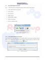
7.2.3 Save a project
This function is to save a project. The project file has an extension of “.smp”. To save a
project, click the
button. The project can be loaded for editing using “Load a project”
function. The saved project will have the same file name as the project name by default. You
may wish to save it as another project by simply changing the project name..
Fig. 7 – 5: Save a project
RoboErectus Virtual Simulator Software RE – VSS – CSR User Guide
22
7.2.4 Build a project
This function is to build a project. The built project has an extension of “.dll”. The built
project can be loaded in the control panel via loading AI function. To build a project, click
the
button.
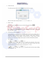
7.2.5 Define a new variable
The RE – VSS – CSR has a set of pre-defined variables. They are Duration, bGameEnd,
CurAction, and CurGame. In addition to the pre-defined global variables, additional variables
can be added for the project. Click on the “Add Variable”
to add a variable. All
parameters, such as variable name, initial value, variable type, etc, associated with the
variable are to be set as shown in Fig. 7 – 6.
Fig. 7 – 6: Add a global variable
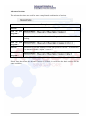
Parameter
What it means …
ArrayLength
The length of the array if the global variable is defined as an array. Set this
parameter to be 0 for other variable types.
Initial value
The initial value of the variable.
Name
Name of the variable. It can only contain „a ~ z‟, „A ~ Z‟, and „0 ~ 9‟.
VarType
Type of the variable. It can be Byte, Int16, Boolean, Float, String, Byte
Array, and Int16 Array.
RoboErectus Virtual Simulator Software RE – VSS – CSR User Guide
23
Step 3: Click
to add the defined variable to the list.
Step 4: Click
to save.
If you wish to delete a global variable from the list, click on “
click on “
”. If you do not wish to save,
”.
7.2.6 Add a team name
This function is to add a team name to the designed project. To add a team name, click the
button “Team Name button
”. The team name must be less than 8 characters.
Fig. 7 – 7: Add a team name
The added team name will be displayed in the scoreboard as well as in the virtual
environment as shown in Fig. 7 – 8..
Fig. 7 – 8: New team nme is displayed
RoboErectus Virtual Simulator Software RE – VSS – CSR User Guide
24
7.2.7. Select a controller board
There are two types of controller board, RE – CS01 board and RE – CS02 board (for Lego
sensors and motors) are used for the CoSpace robot. You can select the controller board used
from the dropdown list as shown in Fig. 7 – 9.
Fig. 7 – 9:Select a controller board
7.3
Statement Management Section
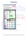
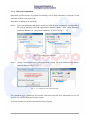
Fig. 7 – 10 shows the statement management section. In this section, you are able to
Add a new statement and a new subroutine;
Define the statement type and state;
Fig. 7 – 10: Statement management section
The RE – VSS – CSR CoSpace platform uses sequential programming technique. The
compiler executes the program statements sequentially in a “top-down” manner. Therefore,
the order of the statements in the program plays a very important role in deciding the priority
of statements with the same priority.
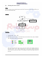
In order to synchronise the real and virtual robots and maintain real-time data updating, the
CoSpace platform RE – VSS – CSR automatically scans all sensors‟ readings in an interval
of 60 ms. In other words, all the variables associated with sensors will be updated every 60
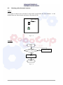
ms. Fig. 7 – 11 shows the program execution flow.
RoboErectus Virtual Simulator Software RE – VSS – CSR User Guide
25
Scan Begins; Scan Time = 0
Read all sensors’ value
CoSpace Program
Begin
Re-arrange all statements
according to the priorities
Is the statement with the highest
priority executed?
Yes
No
Is the statement with the 2nd-highest
priority executed?
Yes
No
Default Statement
End
Wait until: Scan Time = 60 ms
Fig. 7 – 11: Program execution flow
RoboErectus Virtual Simulator Software RE – VSS – CSR User Guide
26
7.3.1 Add a new statement
Statement specifies action. A program is formed by one or more statements in sequence. Each
statement will have an expression.
Procedure of adding new statement:
Step1: Select the statement/subroutine which you wish the new statement to be appended in
the project and then click the right mouse button. Choose “Add a new statement
within the Bundle” or “Add a new statement” as shown in Fig. 7 – 12.
or
Fig. 7 – 12: Adding a new statement
Step 2: Assign a meaningful name to the statement created. The new statement will then be
added as shown in Fig 7 – 13.
Fig. 7 – 13: Assigning a new statement name
The statement type, conditions and actions associated with the new statement need to be
specified. It will be illustrated in later section.
You can continue to add more statements to the program.
RoboErectus Virtual Simulator Software RE – VSS – CSR User Guide
27
7.3.2 Add a new subroutine
A subroutine (also called procedure, method, function, or routine) is a portion of code within
a larger program that performs a specific task and is relatively independent of the remaining
code.
Procedures of adding a new subroutine:
Step 1: Select the previous statement/subroutine in the project that you wish to have the
subroutine appended and click the right mouse button. Choose “Add a new Bundle
within the Bundle” or “Add a new Bundle” as shown in Fig. 7 – 14.
or
Fig. 7 – 14: Adding a subroutine
Step 2: Assign a meaningful name to the subroutine created. The new subroutine will then
be added as shown in Fig 7 – 15.
Fig. 7 - 15: Assigning a new subroutine name
The subroutine is a set of statements. You can add more statements or subroutines to an
existing subroutine.
RoboErectus Virtual Simulator Software RE – VSS – CSR User Guide
28
7.3.3 Managing statements and subroutines
You can delete, move up, move down, and change the statement or subroutine‟s name. To do
so, you need to select the statement or subroutine and right click to select the appropriate
action as shown in Fig. 7 – 16.
Fig. 7 - 16: Managing statement
7.3.4 Statement type
The type of the statement has to be specified when each new statement is added. There are
three types statements for different requirements, namely default action, non-interrupt action,
and super action as shown in Fig. 7 – 17.
Fig. 7 – 17: Statement types
Default action
The default action statement has the lowest priority. A project can have many default
action statements.
Non-interrupt action
The non-interrupt statement has the same priority as the default statement. When the
non-interrupt statement is executed, it will not be interrupted or terminated unless
1) The exit action condition is fulfilled.
2) The super action statement is executed.
RoboErectus Virtual Simulator Software RE – VSS – CSR User Guide
29
When the non-interrupt action is specified, it is necessary to define an exit condition
for this action. That means the non-interrupt statement will only be terminated when
the specified exit condition is true.
The Section 7.3.5 on managing states will illustrate the details.
A project can contain many non-interrupt action statements.
Super action:
The super-action statement has the highest priority. Once the condition for the
statement is true, it will be executed immediately. All other actions will be
interrupted.
A project can contain many super action statements.
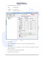
7.3.5 Managing states
State Manager allows you to add/delete new state variables and define the states.
Fig. 7 – 18: State manager
A state is needed for a non-interrupt statement. When a new state is defined, it is compulsory
to specify the exit-action condition. The non-interrupt statement will only be terminated when
the exit-condition is true. Fig. 7 – 19 shows the state manager environment.
Fig. 7 – 19: State manager
RoboErectus Virtual Simulator Software RE – VSS – CSR User Guide
30
Add a new state
To add a new state, double click the
and specify the new state.
Fig. 7 – 20: Add a new state
The new state name can only contain „a ~ z‟, „A ~ Z‟, and „0 ~ 9‟.
Delete a state
To delete a state, highlight the state you wish to delete and click the
Save a state
Just simply click on the
the states will be saved.
.
button. The state manager window will be closed and
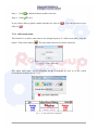
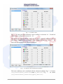
Define an exit-action condition
In this platform, we can define the exit-condition based on the sensor readings from 4
ultrasonic sensors (Ultrasonic Sensor Front, Ultrasonic Sensor Back, Ultrasonic
Sensor Left, Ultrasonic Sensor Right), 1 Direction Sensors, 2 colour sensors (Colour
Sensor Left, Colour Sensor Right), time sequence and other self-defined variables.
For example,
specifies the ultrasonic front sensor
reading is in between 10 and 50 cm. That means that distance between the front
obstacle and the front ultrasonic sensor is in between 10 – 50 cm.
specifies the left colour sensor reading
is in between 10 – 30.
RoboErectus Virtual Simulator Software RE – VSS – CSR User Guide
31
Fig. 7 – 21: Define a state
Fig. 7 – 21 shows the front ultrasonic sensor reading is in between 10 – 50 and left
colour sensor reading is in between 10 – 30.
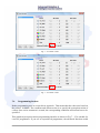
The advanced condition can be used to specify more complex conditions, such as
(US_Front>=10&&US_Front<=50)||(CS_Left>=10&&CS_Left<=30) . Fig. 7 – 22
shows the implementation of advanced condition.
Fig. 7 – 22: Define a state with advanced condition
The basic conditions can be combined with the advanced condition. Fig. 7 – 23 shows
(US_Front>=0&&US_Front<=50)&&(CS_Left<50). Fig. 7 – 24 shows
(US_Front>=0&&US_Front<=50)||(CS_Left<50).
RoboErectus Virtual Simulator Software RE – VSS – CSR User Guide
32
Fig. 7 – 23: Define a state
Fig. 7 – 24: Define a state
7.4
Programming Section
Robot programming uses an event-driven approach. That means that the robot acts based on
the sensors‟ feedback. The condition and action section is to specify the perception-action of
a robot. Once a new statement is created, the corresponding conditions and actions have to be
specified.
This graphical perception-action programming interface as shown in Fig 7 – 25 is suitable for
a novice programmer. If you are an experienced programmer, the advanced function would
RoboErectus Virtual Simulator Software RE – VSS – CSR User Guide
33
better suit your needs. Of course, the package also provides an interface for proficient C++
programmers to write their own C++ code.
Fig. 7 – 25: Graphical Programming Interface
7.4 1 Basic conditions
The following sensors readings are used for specifying conditions.
US_Front – feedback value from the front ultrasonic sensor
US_Back – feedback value from the back ultrasonic sensor
US_Left – feedback value from the left ultrasonic sensor
US_Right – feedback value from the right ultrasonic sensor
CS_Left – feedback value from the left colour sensor
CS_Right – feedback value from the right colour sensor
Direction – feedback value from the compass sensor
Time – Time sequence
RoboErectus Virtual Simulator Software RE – VSS – CSR User Guide
34
You can also use self-defined variables.
RE–VSS–CSR uses a perception based programming strategy. You just need to specify the
conditions and action. Fig. 7 – 26 shows the condition/action panel.
Edit Max Value
Edit Min Value
Set motor speed
Set LED mode
Fig. 7 – 26: Programming panel
The simple conditions can be defined using the slider to specify the data range.
Examples
Condition
0 ≤ Front Ultrasonic Sensor Reading ≤ 50
How do you
program…
Condition
40 ≤ Back Ultrasonic Sensor Reading ≤ 80
How do you
program…
RoboErectus Virtual Simulator Software RE – VSS – CSR User Guide
35
Condition
0 ≤ Left Colour Sensor Reading ≤ 60
How do you
program…
Condition
0o ≤ Compass Sensor Reading ≤ 45o
How do you
program…
You can combine any two or more conditions using the same method. Please note that the
relationship between these conditions will be “Logical AND”.
Examples
Condition
0 ≤ Front Ultrasonic Sensor Reading ≤ 50
and
0 ≤ Left Colour Sensor Reading ≤ 60
How do you
program…
Condition
How do you
program…
0 ≤ Front Ultrasonic Sensor Reading ≤ 50
or
0 ≤ Left Colour Sensor Reading ≤ 60
Use advanced condition
RoboErectus Virtual Simulator Software RE – VSS – CSR User Guide
36
Condition
40 ≤ Back Ultrasonic Sensor Reading ≤ 80
and
Right Colour Sensor Reading ≥ 100
How do you
program…
Condition
How do you
program…
Condition
40 ≤ Back Ultrasonic Sensor Reading ≤ 80
or
Right Colour Sensor Reading ≥ 100
Use advanced condition
0 ≤ Left Colour Sensor Reading ≤ 60
and
o
45 ≤ Compass Sensor Reading ≤ 90o
How do you
program…
RoboErectus Virtual Simulator Software RE – VSS – CSR User Guide
37
7.4.2 Basic action
Define robot moving direction
Movement
Left Wheel
Right Wheel
Robot moves forward
Positive Value, e.g. “+1”
Positive Value
Robot turns right
Positive Value
Negative Value, e.g. “- 1”
Robot turns left
Negative Value
Positive Value
Robot moves backwards
Negative Value
Negative Value
Define robot moving speed
Speed Setting
Motor Speed
0
Stop
1
Robot moves at 20% of its full speed
2
Robot moves at 40% of its full speed
3
Robot moves at 60% of its full speed
4
Robot moves at 80% of its full speed
5
Robot moves at full speed
Set LED display
LED Setting
What it means…
0
LED – off
1
LED – blinks
2
LED – steady display
Duration
Duration is used to specify the duration for the action. The action will be continuously
executed for the period that is specified in duration. The unit for duration is 60ms.
Game End
If the Game End box is checked, the entire game will end when this statement is
executed.
RoboErectus Virtual Simulator Software RE – VSS – CSR User Guide
38
Examples
Actions
Robot moves forward with 40% of the full speed for 120 ms
How do you
program…
Actions
Robot moves forward with 40% of the full speed for 120 ms while
LED is flashing.
How do you
program…
Actions
Robot moves forward with 40% of the full speed for 120 ms. At mean
time, The internal variable “Alpha” is set to 5.
How do you Use advanced action.
program…
7.4.3 Advanced programming function
In the advanced function, you can write simple codes for specific conditions and actions.
The Advanced programming supports the symbols for C arithmetic operations and relational
operators.
You can use all pre-defined variables and global variables specified in the advanced
conditions and actions.
RoboErectus Virtual Simulator Software RE – VSS – CSR User Guide
39
Advanced Conditions
The advanced conditions are used for more complicated combination of conditions.
Examples
Condition
0 ≤ Front Ultrasonic Sensor Reading ≤ 50
and
0 ≤ Left Colour Sensor Reading ≤ 60
How do you
program…
Condition
0 ≤ Front Ultrasonic Sensor Reading ≤ 50
or
0 ≤ Left Colour Sensor Reading ≤ 60
How do you
program…
Condition
40 ≤ Back Ultrasonic Sensor Reading ≤ 80
and
Right Colour Sensor Reading ≥ 100
How do you
program…
(US_Back>=40&&US_Back<=80)&&(CS_Right>=100)
Condition
40 ≤ Back Ultrasonic Sensor Reading ≤ 80
or
Right Colour Sensor Reading ≥ 100
How do you
program…
(US_Back>=40&&US_Back<=80)||(CS_Right>=100)
Condition
0 ≤ Left Colour Sensor Reading ≤ 60
and
o
45 ≤ Compass Sensor Reading ≤ 90o
How do you
program…
(CS_Left<=60)&&(Compass>=45&&Compass<=90)
RoboErectus Virtual Simulator Software RE – VSS – CSR User Guide
40
The advanced conditions can be combined with the basic conditions to fulfill more
comprehensive requirement.
Condition
Examples
0 ≤ Front Ultrasonic Sensor Reading ≤ 50
and
0 ≤ Left Ultrasonic Sensor Reading ≤ 40
or
0 ≤ Left Colour Sensor Reading ≤ 60
How do you
program…
Condition
0 ≤ Front Ultrasonic Sensor Reading ≤ 50
or
0 ≤ Left Ultrasonic Sensor Reading ≤ 50
or
0 ≤ Left Colour Sensor Reading ≤ 60
How do you
program…
RoboErectus Virtual Simulator Software RE – VSS – CSR User Guide
41
Advanced Actions
The advanced actions are used for more complicated combination of actions.
Examples
Actions
Robot moves forward with 40% of the full speed for 120 ms
How do you
program…
Actions
Robot moves forward with 40% of the full speed for 120 ms while LED is
flashing.
How do you
program…
Actions
Robot moves forward with 40% of the full speed for 120 ms. At mean time,
The internal variable “Alpha” is set to 5.
How do you
program…
Please note that when the advanced action is created, it overwrites the basic actions for the
same variables.
RoboErectus Virtual Simulator Software RE – VSS – CSR User Guide
42
7.5
C++ Programming Interface
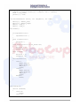
When a project is built, there will be two files, namely “ai.cs” and “ai.c” generated
automatically.
“ai.cs” is a CSharp program. It is generated according to the graphical programming.
The “ai.cs” can be further modified and then be compiled and run in the virtual
environment.
“ai.cs” can be opened using Note Pad or Microsoft Visual Studio.net.
using System;
namespace AI
{
public static class AI
{
static int Duration = 0;
static int SuperDuration = 0;
static bool bGameEnd = false;
static int CurAction = 0;
static int CurGame = 0;
static int US_Front = 0;
static int US_Back = 0;
static int US_Left = 0;
static int US_Right = 0;
static int CS_Left = 0;
static int CS_Right = 0;
static int Compass = 0;
static int Time = 0;
static int Wheel_Left = 0;
static int Wheel_Right = 0;
static int LED_1 = 0;
public static string GetTeamName()
{
return "Happy";
}
public static void SetGameID(int GameID)
{
CurGame = GameID;
bGameEnd = false;
}
public static int GetGameID()
{
return CurGame;
}
public static bool IsGameEnd()
{
return bGameEnd;
}
RoboErectus Virtual Simulator Software RE – VSS – CSR User Guide
43
public static void OnTimer()
{
switch (CurGame)
{
case 100:
break;
case 101:
Wheel_Left=0;
Wheel_Right=0;
LED_1=0;
break;
case 0:
Game0();
break;
default:
break;
}
}
public static void SetData(int Sensor0 , int Sensor1 , int Sensor2
, int Sensor3 , int Sensor4 , int Sensor5 , int Sensor6 , int Sensor7)
{
US_Front = Sensor0;
US_Back = Sensor1;
US_Left = Sensor2;
US_Right = Sensor3;
CS_Left = Sensor4;
CS_Right = Sensor5;
Compass = Sensor6;
Time = Sensor7;
}
public static void GetCommand(ref int Actuator0 , ref int Actuator1
, ref int Actuator2)
{
Actuator0 = Wheel_Left;
Actuator1 = Wheel_Right;
Actuator2 = LED_1;
}
private static void Game0()
{
if(SuperDuration>0)
{
SuperDuration--;
}
else if(Duration>0)
{
Duration--;
}
else if(US_Front>=0 && US_Front<=30)
{
Duration = 0;
CurAction =0;
}
else if(true)
{
Duration = 0;
CurAction =1;
}
switch(CurAction)
{
RoboErectus Virtual Simulator Software RE – VSS – CSR User Guide
44
case 0:
Wheel_Left=0;
Wheel_Right=0;
LED_1=0;
break;
case 1:
Wheel_Left=2;
Wheel_Right=2;
LED_1=0;
break;
default:
break;
}
}
}
}
RoboErectus Virtual Simulator Software RE – VSS – CSR User Guide
45
“ai.c” is a C program. It is generated according to the graphical programming. The
“ai.c” can be further modified and then be compiled and downloaded onto the real
robot. The real robot will perform in the real environment according the program
edited in the environment.
////////////////////////////
//The ID : It must be three digital number. Value is from "001" to "999".
"000" is reserved.
char AI_MyID[3] = "002";
///////////////////////////////////
#define true 1
#define false 0
int AI_MotorType = 0;
int Duration = 0;
int SuperDuration = 0;
int bGameEnd = false;
int CurAction = 0;
int CurGame = 0;
int US_Front = 0;
int US_Back = 0;
int US_Left = 0;
int US_Right = 0;
int CS_Left = 0;
int CS_Right = 0;
int Compass = 0;
int Time = 0;
int Wheel_Left = 0;
int Wheel_Right = 0;
int LED_1 = 0;
int AI_SensorNum = 7;
void SetGameID(int GameID)
{
CurGame = GameID;
bGameEnd = false;
}
int GetGameID()
{
return CurGame;
}
int IsGameEnd()
{
return bGameEnd;
}
void SetData(int *packet, int *CCP , int *ADC , int compass, int play_time)
{
int sum = 0;
US_Front = CCP[0]; packet[0] = US_Front; sum += US_Front;
US_Back = CCP[1]; packet[1] = US_Back; sum += US_Back;
US_Left = CCP[2]; packet[2] = US_Left; sum += US_Left;
US_Right = CCP[3]; packet[3] = US_Right; sum += US_Right;
CS_Left = ADC[2]; packet[4] = CS_Left; sum += CS_Left;
RoboErectus Virtual Simulator Software RE – VSS – CSR User Guide
46
CS_Right = ADC[3]; packet[5] = CS_Right; sum += CS_Right;
Compass = compass; packet[6] = Compass; sum += Compass;
Time = play_time;
packet[7] = sum;
}
void GetCommand(int *Motor, int *LegoMotor, int *LED)
{
Motor[0] = Wheel_Left;
Motor[2] = Wheel_Right;
LED[0] = LED_1;
LED[1] = LED_1;
}
void Game0()
{
if(SuperDuration>0)
{
SuperDuration--;
}
else if(Duration>0)
{
Duration--;
}
else if(US_Front>=0 && US_Front<=30)
{
Duration = 0;
CurAction =0;
}
else if(true)
{
Duration = 0;
CurAction =1;
}
switch(CurAction)
{
case 0:
Wheel_Left=0;
Wheel_Right=0;
LED_1=0;
break;
case 1:
Wheel_Left=2;
Wheel_Right=2;
LED_1=0;
break;
default:
break;
}
}
void OnTimer()
{
switch (CurGame)
{
case 100:
break;
case 101:
RoboErectus Virtual Simulator Software RE – VSS – CSR User Guide
47
Wheel_Left=0;
Wheel_Right=0;
LED_1=0;
break;
case 0:
Game0();
break;
default:
break;
}
}
RoboErectus Virtual Simulator Software RE – VSS – CSR User Guide
48
8.
Practical Guide
8.1
Manual control of robot
The RE – VSS – CSR provides a manual control interface. When you use a mouse to control
the dashboard, the robot will move accordingly.
Up
Right
Left
Down
Fig. 8 – 1 Robot manual control
RoboErectus Virtual Simulator Software RE – VSS – CSR User Guide
49
8.2
Working with ultrasonic sensors
Task 1:
To program a robot to move forward. It stops when it approaches the front obstacle. i.e. the
distance between front obstacle and robot is less than 20 cm.
D <=20 cm
Fig. 8 – 2
Analysis:
Begin
D <= 20cm ?
No
Move Forward
Yes
Stop
End
Fig. 8 – 3
RoboErectus Virtual Simulator Software RE – VSS – CSR User Guide
50
Procedure:
1. Launch the RE – VSS – CSR.
2. Launch the AI developer panel
3. Create a new project.
4. Add a statement namely “Stop”.
Type:
Default Action
Condition:
When the reading from front ultrasonic sensor <= 20 cm
Action:
Both wheels speed = 0 (stop position)
Fig. 8 – 4
RoboErectus Virtual Simulator Software RE – VSS – CSR User Guide
51
5. Add a statement namely “Forward”.
Type:
Default Action
Condition:
no restrictions
Action:
Both wheels speed = “+2”
Fig. 8 – 5
6. Save project
The saved project has an extension of “smp”. It can be reloaded for editing.
7. Build project
The built project has an extension of “.dll”. This file can be loaded in the control
panel for execution.
8. Load the built project and start the simulation.
9. Monitor the robot performance.
RoboErectus Virtual Simulator Software RE – VSS – CSR User Guide
52
Task 2:
To program a robot to avoid an obstacle. That means that the robot will turn right when the
front ultrasonic sensor detects an obstacle, i.e. the distance between front obstacle and robot
is less than 20 am.
D <=20 cm
Fig. 8 – 6
Analysis:
Begin
D <= 20cm ?
No
Move Forward
Yes
Turn Right
End
Fig. 8 – 7
RoboErectus Virtual Simulator Software RE – VSS – CSR User Guide
53
Procedure:
1. Launch the RE – VSS – CSR.
2. Launch the AI developer panel
3. Create a new project.
4. Add a statement namely “Turn Right”.
Type :
Default Action
Condition:
When the reading from front ultrasonic sensor <= 20 cm
Action:
Left wheel speed = “+2”, Right wheel speed = “- 2”
Fig. 8 – 8
RoboErectus Virtual Simulator Software RE – VSS – CSR User Guide
54
5. Add a statement namely “Forward”.
Type:
Default Action
Condition:
no restrictions
Action:
Both wheels speed = “+2”
Fig. 8 – 9
6. Save project (MyEx2.smp)
The saved project has an extension of “.smp”. It can be reloaded for editing.
7. Build project (MyEx2.dll)
The built project has an extension of “dll”. This file can be loaded in the control panel
for execution.
8. Load the “MyEx2.dll” in RE – VSS – CSR control panel and start the simulation.
9. Monitor the robot performance.
RoboErectus Virtual Simulator Software RE – VSS – CSR User Guide
55
8.3
Working with compass sensors
Task 1:
To program a robot to turn 1800 until it faces west (Method 1 – using default action).
Fig. 8 – 10
Analysis:
Begin
171 <=Compass Reading <= 190 ?
No
Turn Right
Yes
Stop
End
Fig. 8 – 11
RoboErectus Virtual Simulator Software RE – VSS – CSR User Guide
56
Procedure:
1. Launch the RE – VSS – CDR.
2. Launch the AI developer panel
3. Create a new project.
4. Add a new statement “Stop”.
Type :
Default Action
Condition:
When Compass sensor reading is in between 171 and 190 degree.
Action:
Left wheel speed = “0”, Right wheel speed = “0”
Fig. 8 – 12
RoboErectus Virtual Simulator Software RE – VSS – CSR User Guide
57
5. Add a new statement “Turn Right”.
Type :
Default Action
Condition:
No restrictions.
Action:
Left wheel speed = “+1”, Right wheel speed = “-1”
Fig. 8 – 13
6. Save the project as “MyEx3.smp”.
7. Build the project as “MyEx3.dll”.
8. Load the “MyEx3.dll” in RE – VSS – CSR control panel and start the simulation.
9. Monitor the robot performance.
RoboErectus Virtual Simulator Software RE – VSS – CSR User Guide
58
Task 2:
To program a robot to turn 1800 until it faces west (Method 2 – using Non-interrupt action).
Fig. 8 – 14
Analysis:
Begin
171 <=Compass Reading <= 190 ?
No
Turn Right
Yes
Stop
End
Fig. 8 – 15
RoboErectus Virtual Simulator Software RE – VSS – CSR User Guide
59
Procedure:
1. Launch the RE – VSS – CSR.
2. Launch the AI developer panel.
3. Create a new project.
4. Add a new statement “Right Turn”.
Type :
Non_Interrupt
Add a new exit state using state manager:
Fig. 8 – 16
Set the exit action condition to be
, That
means that when 171 <= Compass Reading <= 190 is true, the Non Interrupt action
statement “Turn Right” will be terminated. The next statement in the program will be
executed.
Condition:
“(Compass>=0 && Compass<=170) || (Compass>=190 && Compass<=360)”
This statement means:
When the condition (0 <= Compass sensor reading <=170) or (191 <= Compass
sensor reading <=360) is fulfilled, the “Right Turn” statement will be executed.
RoboErectus Virtual Simulator Software RE – VSS – CSR User Guide
60
Action:
Left wheel speed = “+1”, Right wheel speed = “-1”
Fig. 8 – 17
RoboErectus Virtual Simulator Software RE – VSS – CSR User Guide
61
5. Add a new statement “Stop”.
Type :
Default Action
Condition:
No restrictions.
Action:
Left wheel speed = “0”, Right wheel speed = “0”
Fig. 8 – 18
6. Save the project as “MyEx4.smp”.
7. Build the project as “MyEx4.dll”.
8. Load the “MyEx4.dll” in RE – VSS – CSR control panel and start the simulation.
9. Monitor the robot performance.
RoboErectus Virtual Simulator Software RE – VSS – CSR User Guide
62
8.4
Working with colour sensors
Task 1:
Program a robot to locate a black object in the field. The robot will stop with an LED on for
the successful identification.
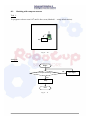
Analysis:
Begin
Object Found?
No
Move Forward
Yes
Stop with LED on
End
Fig. 8 – 19
Procedure:
1. Launch the RE – VSS – CSR.
2. Manually move the robot over the black object and read the colour sensor feedback.
This value will be used for programming.
Fig. 8 – 20
This means that when the colour sensor senses the red object, the reading is about 40.
The robot in RE – VSS – CSR is installed with 2 colour sensors. Both left and right
colour sensors can detect the object. The readings for both left and right sensors are
the same.
RoboErectus Virtual Simulator Software RE – VSS – CSR User Guide
63
3. Launch the AI developer panel.
4. Create a new project.
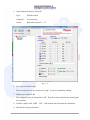
5. Add a new statement “Left Sensor Found Object”.
Type :
Default Action
Condition:
Left colour sensor reading is less than 85.
Action:
Left wheel speed = “0”, Right wheel speed = “0”, LED is on
Fig. 8 – 21
RoboErectus Virtual Simulator Software RE – VSS – CSR User Guide
64
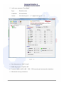
6. Add a new statement “Right Sensor Found Object”.
Type :
Default Action
Condition:
Right colour sensor reading is less than 42.
Action:
Left wheel speed = “0”, Right wheel speed = “0”, LED is on
Fig. 8 – 22
RoboErectus Virtual Simulator Software RE – VSS – CSR User Guide
65
7. Add a new statement “Move Forward”.
Type :
Default Action
Condition:
No restrictions.
Action:
Left wheel speed = “+1”, Right wheel speed = “+1”
Fig. 8 – 23
8. Save the project as “MyEx5.xml”.
9. Build the project as “MyEx5.dll”.
10. Load the “MyEx5.dll” in RE – VSS – CSR control panel and start the simulation.
11. Monitor the robot performance.
RoboErectus Virtual Simulator Software RE – VSS – CSR User Guide
66
9.
MPLAB IDE, MPLAB C30 and PICkit 2 for PIC Microcontroller
9.1
Get Ready
CoSpace robot is equipped with PIC microcontroller. Therefore, MPLAB IDE, MPLABC30
Compiler, and PICkit2 are required for program compiling and downloading to real robot
controller.
9.1.1 MPLAB Integrated Development Environment (IDE) and MPLAB C30 Compiler
MPLAB Integrated Development Environment (IDE) is a comprehensive editor, project
manager and design desktop for application development of embedded designs using
Microchip PIC MCUs and dsPIC DSCs.
MPLAB IDE provides the ability to:
Create and edit source code using the built-in editor.
Assemble, compile and link source code.
Debug the executable logic by watching program flow with the built-in simulator or
in real time with in-circuit emulators or in-circuit debuggers.
Make timing measurements with the simulator or emulator.
View variables in watch windows.
Program firmware into devices with device programmers (for details, consult the
user‟s guide for the specific device programmer).
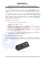
9.1.2 PICkit 2 MCU Programmer/Debuger
The PICkit 2 Development Programmer/Debugger is a low-cost development programmer. It
is capable of programming most of Microchips Flash microcontrollers and serial EEPROM
devices.
Fig. 9 – 1: PICkit 2
RoboErectus Virtual Simulator Software RE – VSS – CSR User Guide
67
9.2
Installation
9.2.1 Install/Uninstall MPLAB IDE
To install MPLAB IDE on your system:
If installing from a CD-ROM, place the disk into a CD Drive. Follow the on-screen menu
to install MPLAB IDE. If no on-screen menu appears, use Windows Explorer to find and
execute the CD-ROM menu, menu.exe.
If downloading MPLAB IDE from the Microchip website (www.microchip.com), locate
the download (.zip) file, select the file and save it to the PC. Unzip the file and execute
the resulting setup.exe file to install.
Please note: Before the installation is completed, you will be asked to install “HITECH”. Please select “NO” to end.
To uninstall MPLAB IDE:
Select Start > Settings > Control Panel to open the Control Panel.
Double click on Add/Remove Programs. Find MPLAB IDE on the list and click on it.
Click Change/Remove to remove the program from your system.
9.2.2 Install/Uninstall MPLAB C30 Compiler
To install MPLAB C30 Compiler on your system:
Download and install
(www.microchip.com):
the
following
compiler
from
Microchip
website
MPLAB C Compiler for PIC24 MCUS and dsPIC DSCs, academic version.
To uninstall MPLAB C30 Compiler:
Select Start > Settings > Control Panel to open the Control Panel.
Double click on Add/Remove Programs. Locate & select the “MPLAB C for dsPIC DSCs
and PIC24 MCUs”.
Click “uninstall” button to uninstall it from your system.
**Both MPLAB IDE & MPLAB C30 Compiler must be installed on the system. Failure
to do so may cause failure/errors when compiling the project.
RoboErectus Virtual Simulator Software RE – VSS – CSR User Guide
68
9.2.3 Install/Uninstall PICkit 2 (PICkit2need to be purchased)
To install the PICkit 2 on your system
Insert the PICkit™ 2 Starter Kit CD ROM into the CD ROM drive. In a few moments,
the introductory screen should appear. Follow the directions on the screen for installing
the PICkit™ 2 Programming Software. If the introductory screen does not appear, browse
to the CD ROM directory and select the Setup.exe program.
To install the PICkit 2 on your system
Select Start > Settings > Control Panel to open the Control Panel.
Double click on Add/Remove Programs. Locate & select the “PICkit 2”,
Click “uninstall” button to uninstall it from your system.
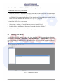
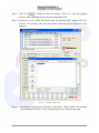
9.3
Running MPLAB IDE
To start MPLAB IDE, double click on the icon installed on the desktop after installation or
select Start > Programs > Microchip > MPLAB IDE v8.xx > MPLAB IDE. A screen will
appear displaying the MPLAB IDE logo followed by the MPLAB IDE desktop as shown in
Fig. 9 – 2.
Fig. 9 – 2 : MPLAB IDE Desktop
RoboErectus Virtual Simulator Software RE – VSS – CSR User Guide
69
In order to create code that is executable by the target PIC Microcontroller unit, source files
need to be put into a project. The codes can then be built into executable code using selected
language tools (assemblers, compilers, linkers, etc.). In MPLAB IDE, the project manager
controls this process. All projects will have these basic steps:
1. Create Project
2. Select Device
3. Select Language Tools
4. Put Files in Project
5. Create Code
6. Build Project
7. Test Code with Simulator
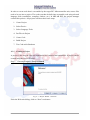
9.3.1 Creating a Project
A project is the way the files are organized to be compiled and assembled. A project can be
created using the Project Wizard.
Step 1: Choosing Project > Project Wizard
Fig. 9 – 3: Project Wizard – Welcome
From the Welcome dialog, click on “Next” to advance.
RoboErectus Virtual Simulator Software RE – VSS – CSR User Guide
70
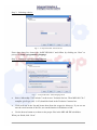
Step 2: Selecting a device
Fig. 9 – 4: Project Wizard – Select Device
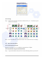
From drop down list, choose the “dsPIC30F6014A” and follow by clicking on “Next” to
proceed to setup a programming language.
Step 3: Setting up a programming language
Fig. 9 – 5: Project Wizard – Select language tools
Select “Microchip C30 Toolsuite” in the Active Toolsuite list box. Then MPLAB C30 C
compiler (pic30-gcc.exe) v3.25) should be listed in the Toolsuite Contents box.
Click each one in the list and locate them from the respective directory. If you are not
sure the exact location of the file, use search function in Windows to find.
Use the browse button to set them to the proper files in the MPLAB IDE subfolders.
When you finish, click “Next”.
RoboErectus Virtual Simulator Software RE – VSS – CSR User Guide
71
Step 4: Naming a new project and put it into a folder
Fig. 9 – 6: Name Project
In this example, we will create a sample project will be called C:\Projects\MyProject. Type
this into the text box and then click “Next”. You will be prompted to create the directory
since it does not exist. Click OK.
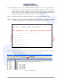
Step 5: Adding files
Select the necessary files (motherboard.o, motherboard.h, main.c, and main.h) and click
“Add” to add them into the right panel.
Fig. 9 – 7: Adding files
Once it is done, clicking “Next” will show up a project summary dialog.
The project summary dialog summaries the selected device, the toolsuite, and the new project
file name.
RoboErectus Virtual Simulator Software RE – VSS – CSR User Guide
72
Fig. 9-8: Project summary
Click on “Finish” to generate the project and proceed to the “MPLAB WorkSpace”
Step 6: Viewing the Project
You can select View > Project in menu bar to view the project created.
Fig. 9-9: MPLAB WorkSpace
Files can be added and project can be saved by clicking the right mouse button in the project
window. In case of error, files can be manually removed from the project by selecting them;
clicking the right mouse button and selecting “Remove” from the menu.
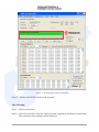
9.3.2 Building a project
“Build a project” is to compile and link all the source files for an application.
Double click on the project created. In the MPLAB IDE menu, select Project > Build All.
RoboErectus Virtual Simulator Software RE – VSS – CSR User Guide
73
The output window shows the result of build process. There should be no errors or warning at
any step. However, if you do receive errors, go back to the previous sections and check the
project assembly steps. Errors will prevent the project from building. If you receive warnings,
you may ignore them for this project as they will not prevent the project from building.
Fig. 9-10: Output window
If you follow all the steps mentioned previously, you will get the message “BUILD
SUCCEEDED” as shown in Fig. 9-10 shown above on your output window when you select
“Build All”.
9.4
PICkit 2 Programming Interface
Start the PICkit™ 2 Programming Software by selecting Start > Programs > Microchip >
PICkit 2. The programming interface appears as shown in Fig. 9 – 11.
Fig. 9 – 11: PICkit 2 programming interface
9.4.1 Checking Communication
RoboErectus Virtual Simulator Software RE – VSS – CSR User Guide
74
Plug PICkit 2 into both computer and Robot controller board. To test the communication.
select the Tools > check communication. The message “PICkit 2 found and connected” will
be displayed in the status bar.
RoboErectus Virtual Simulator Software RE – VSS – CSR User Guide
75
10.
Working with Real Robots
Upon successful compilation and building of a project, “ai.c” – a C code file, is automatically
generated. The “ai.c” can be downloaded to the real robot. Of course, you can open the ai.c
file to study the programming logics if you wish do. You can also modify the C code for
further improvement. This feature allows students to program a robot controlled by a
microcontroller without writing a C code for any specific microcontroller.
10.1 Install ZigBee Modules
The real robot communicates with the virtual control/competition panels via ZigBee
communication protocol. Hence, it is necessary to make sure that the ZigBee modules are
connected to the real robot and the computer properly. If this is your first time using ZigBee,
you need to install “FT232R USB UART Driver” for the ZigBee module. Appendix B shows
the procedures of determining the correct com port connected with the ZigBee module.
10.2 Manual Control of Real Robots
10.2.1 Connecting the real robot
Step 1: Identify the com port ID used to connect the ZigBee module.
Step 2: Double click the robot icon in the control panel as shown in Fig. 10 – 1.
Virtual
Robot #1
Virtual
Robot #2
Real
Real
Robot #1 Robot #2
Dashboard #1
Dashboard #2
Game Controller #1
Game Controller #2
Fig. 10 – 1: Robot control configuration
Step 3: Assign the correct com port and robot ID in the pop-up window. The robot ID must
be unique. It has to be the same as the robot ID assigned to the real robot.
RoboErectus Virtual Simulator Software RE – VSS – CSR User Guide
76
Fig. 10 – 2: Connect real robot window
10.2.2 Testing
Step 1: Double click on the blue cross button as indicated in Fig. 10 – 3. It will turn to green
tick once it is connected.
Real
Robot
#1
Dashboard
#1
Fig. 10 – 3: Manual control of a real robot
Step 2: Move the dashboard to control the real robot. The real robot will move accordingly.
10.3
Fully Autonomous Robot
10.3.1 Connecingt the real robot
Repeat the steps stated in 10.2.1 to establish the communication via ZigBee.
10.3.2 Download the Program into the Real Robot
Step 1: Copy the folder RealAI from the CD or from the following website to your own PC.
RoboErectus Virtual Simulator Software RE – VSS – CSR User Guide
77
Step 2: Substitute the file “ai.c” in the RealAI folder with the new “ai.c” generated. The
same file name must be retained. As the lighting condition in real environment
varies and it is certainly different from the virtual world, the sensor readings will
change. Therefore, it is important to do a sensor calibration and make necessary
changes in the program before downloading it onto the real robot.
Step 3: Launch the MPLAB workspace and open a project called RE2009PIC.mcp.
Step 4: In order to receive the real-time feedback from all sensors during the navigation
controlled by a program, it is compulsory to change the robot ID in the “ai.c” file.
////////////////////////////
//The ID : It must be three digital number. Value is
from "001" to "999". "000" is reserved.
char AI_MyID[3] = "002";
Assign the correct robotID
///////////////////////////////////
#define true 1
#define false 0
int AI_MotorType = 0;
int Duration = 0;
int SuperDuration = 0;
int bGameEnd = false;
int CurAction = 0;
Step 5: Build the project. The message “Build Succeeded” will appear upon successful
int CurGame = 0;
building. The compiled file will have an extension “.HEX”.
int US_Front = 0;
Build All
int US_Back = 0;
int US_Left = 0;
int US_Right = 0;
int CS_Left = 0;
int CS_Right = 0;
int Compass = 0;
int Time = 0;
Fig. 10 – 4: Build a project
int Wheel_Left = 0;
int Wheel_Right = 0;
RoboErectusint
Virtual
Simulator
Software RE – VSS – CSR User Guide
LED_1
= 0;
int AI_SensorNum = 7;
78
Step 6: Power off the robot and Connect the PKCKIT2 to controller board.
PICkit 2
USB
Fig. 10 – 5: PICKit 2 connection
Step 7: Launch the PICkit 2 programmer by clicking the “PICkit 2.exe”.
Step 8: Choose “Tool – Check Communication” from the menu bar. The message “PICkit 2
found and connected” will be displayed in the status bar as shown in Fig. 10 – 6.
Fig. 10 – 6: PICkit 2 Communication
RoboErectus Virtual Simulator Software RE – VSS – CSR User Guide
79
Step 9: Click on “
” button to erase the memory. This is to erase the program
memory, data EEPROM memory, ID and configuration bits.
Step 10: Import the correct “.HEX” file built in step 5 by choosing “File – Import HEX file”
function. The message “Hex file successfully imported” will be displayed in the
status bar.
Fig. 10 – 7: Import “.HEX” file
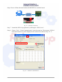
Step 11: Download the program to real robot by clicking the “Write” button. The message
“Programming Successful” will be displayed upon successful downloading.
RoboErectus Virtual Simulator Software RE – VSS – CSR User Guide
80
Fig. 10 – 8: Downloading program to Real Robot
Step 12: Remove the PICKit 2 and test the program.
10.3.3 Testing
Step 1: Power on the robot.
Step 2: Select the real robot from the “Robot Section” segment in the Robo Control Panel.
The real-time sensor readings will be displayed.
RoboErectus Virtual Simulator Software RE – VSS – CSR User Guide
81
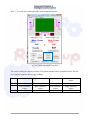
Step 3: You can also control the robot in the competition panel.
Fig. 10 – 9: Real-time control of real robot
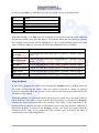
The sensor reading are displayed on the LCD panel attached on the controller board. The two
rows display segments shows eight readings.
Left colour sensor Right colour sensor
Row 1
Row 2
Compass sensor
Front ultrasonic
sensor
0
0
0
0
Front ultrasonic
sensor
Back ultrasonic
sensor
Left ultrasonic
sensor
Right ultrasonic
sensor
10
32
9
526
RoboErectus Virtual Simulator Software RE – VSS – CSR User Guide
82
Appendix A.
A1.
User Guide of Virtual Simulation Environment
Starting Visual Simulation Environment
The Visual Simulation Environment (VSE) provides simulates physical objects and their
interactions including collisions, friction and gravity. It requires a reasonably powerful
graphics card. Please check the requirements below and ensure that your computer satisfies
them.
For best performance hide or close all pop-up windows that may appear on top of the
simulation window.
Microsoft Visual Simulation Environment Graphics Card Requirements
Minimal Requirements
Graphics card supporting DirectX 9.0c (or later) and Shader Model 2.0+ with 64MB
of video memory or greater. Examples include, ATI Radeon 9800+ or NVIDIA FX
series or later.
Recommended Requirements
Graphics card supporting DirectX 9.0c (or later) and Shader Model 3.0+ with 128MB
of video memory or greater. Examples include, ATI Radeon x1300 or NVIDIA 6
series or later.
Minimal Requirements to use GPU Accelerated Physics
NVIDIA GeForce 8, GeForce 9, or GTX 200 series GPU or later, 256MB of video
memory or more required.
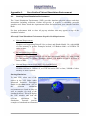
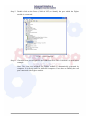
Starting Simulations
To start VSE, select one of the
entries in the VSE folder under
Microsoft Robotics Developer
Studio in the Start menu. (All of
the
different
simulation
environments are listed in there as
well as samples for each of the
simulated robots.) This will display
the VSE window and load the
relevant
simulation.
The
Simulation
Tutorials
provide
examples of simulated environments.
RoboErectus Virtual Simulator Software RE – VSS – CSR User Guide
83
When the simulator is running, you can move the camera viewpoint by dragging the mouse
pointer across the screen. It does not change the camera position but it changes the point that
the camera is looking at.
To move the camera, you can use the keyboard as follows
Key
Action
w or Up Arrow
moves forward
s or Down Arrow
moves backward
a or Left Arrow
moves left
d or Right Arrow moves right
q
moves up
e
moves down
If you hold down the Shift key while you hold one of the keys listed above, the camera
moves much faster. You can also use the mouse at the same time as you hold down a key.
This allows you to "fly" around by changing direction with the mouse and moving with the
keyboard.
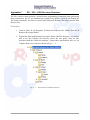
A2.
Visual Simulation Environment Menus
The following commands are provided on the Microsoft Visual Simulation Environment
(VSE) window.
The File Menu
Open Scene - Loads a scene.
Save Scene As - Saves a scene. When you save a scene, the simulator saves the
simulator state along with the state for every entity in the scene. It also saves a
manifest which can be used to re-initialize the scene and any services associated with
the entities.
Save Material Changes - Saves changes made to materials in Edit mode.
Open Manifest - Load a service manifest.
Create Embedded Resources - Creates a single saved file containing all effects,
textures, meshes, etc.
Capture Image As - Save the current view of the simulation to a file.
RoboErectus Virtual Simulator Software RE – VSS – CSR User Guide
84
Exit - Exits the simulation and shutdown its Decentralized Software Services (DSS)
node. The Simulator will remember the window size and position for the next time it
is started.
The Entity Menu
The Entity Menu is only visible when you select Edit from the Mode menu.
Undo - Undoes the previous change.
Redo - Repeats the last change that was undone.
Cut - Removes the currently checked entities.
Copy - Copies the currently checked entities.
Paste - Adds the last cut or copied entities back into the scene.
Paste As Child - Pastes the last cut or copied entities as a child of the currently
checked entity.
New - Displays a dialog that enables you to create a new entity.
Load Entities - Loads entities from a file.
Save Entities As - Saves the currently checked entities to a file.
The View Menu
Playback bar - Displays the playback bar for recording and playing back recorded
sequences.
Status bar - Displays or hides the status bar. The status bar shows you the current
frame rate in frames-per-second, the simulation time, as well as the current camera
position and look at point.
Profiler - Brings up the Profiler UI dialog.
Look Along - Sets the camera view to a specific viewing axis. Useful for accurately
re-orienting the camera after you have moved it around a lot.
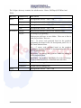
The Render Menu
The first four entries in this menu enables you to change how entities in the simulation are
rendered. You can toggle between these modes using the F2 key.
Visual - Renders a full 3D view. Meshes associated with each entity in the scene are
rendered with realistic lighting and shading.
RoboErectus Virtual Simulator Software RE – VSS – CSR User Guide
85
Wireframe - Renders the scene as a wireframe view. This mode enables you to get a
rough idea of how many polygons make up each mesh and where the polygon edges
are.
Physics - Renders the scene showing physics outlines. This mode enables you to see
how each entity is modeled in the physics engine. The scene is not rendered
completely if the physics engine is disabled.
Combined - Renders the full 3D view with physics. This mode makes it easy for you
to determine how well the physics shapes match the visual mesh for each entity. The
physics part of this scene is not rendered completely if the physics engine is disabled.
No Rendering - This option turns off the rendering to economize on CPU time. The
simulator continues to run.
Graphics Settings - Enables you to change settings that control how the scene is
rendered.
Physics View Settings - Allows you to select the items that are shown in Physics
View.
The Camera Menu
The Camera menu allows you to easily switch between cameras if you have more than
one in the scene. You can press F8 to quickly switch between cameras.
Main Camera - Sets the view from the simulated camera provided by default.
Other cameras - Sets the view from other cameras defined in the current scene. Note
that there are also options to display cameras in separate windows. This allows you to
have, for example, a view from a camera mounted on a robot at the same time as the
main view so that you can see not only what the robot sees but also what it is doing.
This is very useful for diagnosing computer vision programs.
The Physics Menu
Enabled - Enables, or disables, physics forces in the simulation. You can also use the
F3 key to toggle physics on/off.
Settings - Enables you to control whether default camera is treated as a rigid body and
the gravity setting. If the camera option is set, you can use the camera to bump objects
in the scene. You can also adjust the simulation speed.
The Mode Menu
The settings on the Mode menu enable you to change how you can interact with
entities in the scene. Pressing F5 toggles between the options.
RoboErectus Virtual Simulator Software RE – VSS – CSR User Guide
86
Run - The normal operation mode for running your simulation.
Edit - The mode that enables you to edit state of entities in the simulation. This mode
automatically disables Physics.
The Help Menu
Contents - Shows web pages that provide more information about how to use the
various features and controls of the VSE.
About - Shows a dialog that displays information about the version of the VSE and
also information about the current graphics hardware.
A3.
Visual Simulation Environment Keyboard and Mouse
The Visual Simulation Environment (VSE) simulation window provides keyboard and mouse
operations that can be used to control the view and elements in the simulation environment.
Using the Keyboard
The following keys control the movement and orientation of the camera in the simulation
environment when the Simulation pane has input focus. When the Simulation pane has input
focus, it is surrounded by a blue border. Click inside the pane or press the Tab key until the
blue border appears.
Key
Action
w or Up Arrow
Move forward
s or Down Arrow
Move backward
a or Left Arrow
Move to the left (slide sideways)
d or Right Arrow Move to the right (slide sideways)
q or Page Up
Move up
e or Page Down
Move down
Home
Reset to initial position
Note that you can also use the numeric keypad, as long as it is not in numeric mode. In this
case the numeric keys 2, 4, 6 and 8 act as arrow keys.
RoboErectus Virtual Simulator Software RE – VSS – CSR User Guide
87
If you press the Shift key with these keys, the movement keys move 20 times faster.
Key
Action
F2
Change the render mode
F3
Toggle the physics engine enable
F5
Toggle between Edit Mode and Run Mode
F8
Change the active camera
When the simulator is in Edit mode the navigation keys work the same but some additional
options are available when the left Ctrl key is held down. When the left Ctrl key is pressed,
the currently selected entity will be highlighted if it has a valid bounding sphere associated
with it. While the Ctrl key is pressed, the following additional keys are available:
Key
Action
Up Arrow
View the selected object from above (a positive Y distance from the
object)
Shift+Up Arrow
View the selected object from below (a negative Y distance from the
object)
Left Arrow
View the selected object from a positive X distance from the object
Shift+Left Arrow View the selected object from a negative X distance from the object
Right Arrow
View the selected object from a positive Z distance from the object
Shift+Right Arrow View the selected object from a negative Z distance from the object
Using the Mouse
In most cases, dragging the mouse cursor through the Graphics pane by holding down the
left button and moving the mouse causes the camera viewpoint to change. In general,
keyboard commands affect the position of the camera while mouse movement affects the
orientation of the camera.
When the simulator is in Edit mode and the left control key is held down, the mouse behavior
can be different. If an entity is selected and the Position property is selected in the Property
window, the mouse movement affects the position of the entity. If any component of the
position vector is selected, the entity is constrained to move only along that axis. Similarly, if
the rotation property is selected in the Property window, the mouse movement affects the
orientation of the entity. If any component of the rotation vector is selected, the entity is
constrained to rotate only along that axis.
RoboErectus Virtual Simulator Software RE – VSS – CSR User Guide
88
Using an Xbox Controller
If you have an Xbox Controller connected to your PC, you can use it to control the camera as
well. The two thumbsticks on the controller can be used to move the camera around. Note
that you must press and hold the Left Shoulder button (just above the left thumbstick) while
you are moving the camera. This is not immediately obvious.
The movement of the camera is controlled using the left thumbstick and the right thumbstick
is used to pan and tilt the camera as follows (with Left Shoulder held down):
Thumbstick
Direction
Action
Left
Up
Move forward
Left
Down
Move backward
Left
Left
Move to the left (slide sideways)
Left
Right
Move to the right (slide sideways)
Right
Up
Rotate (tilt) up
Right
Down
Rotate (tilt) down
Right
Left
Rotate (pan) left
Right
Right
Rotate (pan) right
IMPORTANT NOTE: If you are using another application that uses the Xbox Controller,
such as the Simple Dashboard, you must make sure that the Simulation window has the input
focus in order to use the controller to move the camera. Click inside the simulation window
with the mouse to give it focus. A blue border appears around the simulation area when it has
focus. If another application has the focus, then you cannot control the simulation camera
using the Xbox Controller.
The simulation coordinate system
The simulator uses a right-handed coordinate system. The +Y axis represents elevation above
the ground plane. The X and Z axes are parallel to the ground plane. When facing in the +X
direction, the +Z axis is to the right. Some modeling tools use a different coordinate system
and it is important to export the models rotated in such a way that they appear correct in the
simulation environment.
RoboErectus Virtual Simulator Software RE – VSS – CSR User Guide
89
Appendix B.
ZigBee Communication Module Setup
Step 1: Launch the Control Panel (Start Settings Control panel)
Fig. B – 1: Launch the Control Panel
Step 2: Double click on the
Fig. B – 2.
icon. The system properties window appears as shown in
Fig. B – 2: System properties
RoboErectus Virtual Simulator Software RE – VSS – CSR User Guide
90
Step 3: Select the Hardware Tab in the system property window.
Fig. B – 3: System Properties
Step 4: Double click on the Device Manager button to explore the device manager.
Fig. B – 4: Device Manager
RoboErectus Virtual Simulator Software RE – VSS – CSR User Guide
91
Step 5: Double click on the Ports (COM & LPT) to identify the port which the Zigbee
module is connected.
Fig. B – 5: Device Manager
Step 6: Check the com port assigned to the USB Serial Port. The COM Port 8 is used in this
example.
Note: The com port assigned for ZigBee module is automatically generated by
computer. It is not the same for different computers. Users have to identify the com
port connected with Zigbee module.
RoboErectus Virtual Simulator Software RE – VSS – CSR User Guide
92
Appendix C.
RE – VSS – CSR Directory Structure
The files, such as entity property, wheeled robot programming, humanoid robot gait tuning
data, performance file etc. are automatically organized by default, if you do not change the
file location manually. All files are stored in the Microsoft Robotics Developer Studio 2008
R3 directory.
To access it,
1. Click on Start All Programs Microsoft Robotics Dev Studio 2008 R3
Robotics Developer Studio,
2. Expend the Microsoft Robotics Developer Studio 2008 R3 directory; you will be
able to see the CoSpace file directory where the user guide, icon, all files
associated with the virtual environment, virtual robot, and manifest files, etc. for
CoSpace Dance are located as shown in Fig. C – 1.
Fig. C – 1: The structure of CoSpace Directory
RoboErectus Virtual Simulator Software RE – VSS – CSR User Guide
93
The CoSpace directory contains four subdirectories: Dance, DIYBiped, DIYWheel and
Entity.
Directory
Subdirectory
Files stored
Dance
Media
Not applicable for RE – VSS - CSR
Property
Not applicable for RE – VSS - CSR
Design
Not applicable for RE – VSS - CSR
Gait
Not applicable for RE – VSS - CSR
Design
Robot design interface (rdi) files for wheeled robots
Project
AI strategies (programing)
DIYBiped
DIYWheel
Each project will have its own folder. There are 4 files in
each project folder. There are
ai.cs – C# source code generated based on the graphical
programing developed in the AI development panel. ai.cs is
for virtual wheeled robot.
ai.c – C source code generated based on the graphical
programing developed in the AI development panel. ai.c is
for real wheeled robot.
MyAI.smp – Ai strategy file. It can be loaded for editing in
AI development panel.
MyAI.DLL – the dynamic link library file of the AI strategy.
It can be loaded to control a virtual/real wheeled robot.
Entity
RealAI
Real robot AI strategy files.
VirtualAI
Virtual robot AI strategy files.
Not applicable for RE – VSS - CSR
RoboErectus Virtual Simulator Software RE – VSS – CSR User Guide
94
Appendix D.
How to Control the Real and Virtual Robots Using
Your Own C Code
The RE – VSS – CSR provides a C programming interface which enables professional
programmers to test the AI strategy using the CoSpace platform. Following are the steps of
creating your own AI strategy for both virtual and real robots.
AI strategy for virtual robot
If you like to write your own AI strategy in Visual C# or modify the ai.cs generated from
graphical programming, you need to
1. Install Visual C# compiler.
2. Copy ai.cs from the project directory to ..\VirtualAI\VirtualAI\ directory and replace
the existing ai.cs file.
3. Launch the visual C# project by double clicking VirtualAI.csproj. The ai.cs will be
the part of the project.
4. Edit the necessary C# code.
5. Build solution to generate the DLL file. The “virtualAI.dll” is created in
\VirtualAI\VirtualAI\bin\Release folder.
6. The “virtual.dll” file can be loaded.
AI strategy for real robot
If you like to write your own AI strategy in C or modify the ai.c generated from graphical
programming (only Game0), you need to
1. Install MPLAB and PICKit 2 downloader. Please refer to session 9 and 10.
2. Copy ai.c from the project directory to realAI directory and replace the existing ai.c
file.
3. Launch the real robot project by double clicking RE2009PIC.mcp. The ai.c will be the
part of the project.
4. Edit the necessary C code.
5. Build ALL to generate/update the RE2009PIC.hex. The “RE2009PIC.hex” is the AI
strategy in the machine language.
6. Download the “RE2009PIC.hex” to the real robot (Session 10 shows the details).
7. Observe the real robot performance.
RoboErectus Virtual Simulator Software RE – VSS – CSR User Guide
95
Appendix E.
Hardware Connection for CoSpace Robot
The RE – VSS – CSR platform provides the same graphical programming interface for the
virtual robots and the real robots. It enables the communication between the real robots and
the CoSpace server. The synchronization of the real robots and the virtual
environment/virtual robots can be realized using the patform. Fig. E – 1 shows the connection
and communication of the CoSpace system.
ZigBee
Com
CoSpace Server
RE – CS
board
Fig E – 1: CoSpace System
In order to program the real robot using the same AI development panel as for the virtual
robot, all sensors, motors and other hardware components must be connected to the controller
board (RE – CS01 or RE – CS02) according to the connection stated in table E – 1.
Table E – 1: The Connection of all Components of a CoSpace Rescue Robot
PIN
Component
RE-CS01
RE-CS02
(LEGO)
Left
Motor 1 [DUO] Motor 1 [LEGO]
Right
Motor 2 [DUO] Motor 3 [LEGO]
Front
CCP1
CCP1
Ultrasonic
Back
CCP2
CCP2
Sensor
Left
CCP3
CCP3
Right
CCP4
CCP4
Left
ADC2
ADC2
Right
ADC3
ADC3
Compass
DI/01
I/01
Speed scale [-5, +5]
Wheel
Distance in centimeter.
Brightness value
Color Sensor
Compass
Unit
RoboErectus Virtual Simulator Software RE – VSS – CSR User Guide
Degree
96
In the AI development panel, a prompt message will show you again the correct pin
connection when the mouse hover over a ComboBox, Slider or TextBox as shown in Fig. E –
2.
Fig. E – 2: The connection of each component.
Please refer to the RE – CS01 and RE – CS02 User Guide for the educational controller
board.
RoboErectus Virtual Simulator Software RE – VSS – CSR User Guide
97
Appendix F.
Communication Protocol
One device is able to communicate with many devices via ZigBee communication. Hence,
the CoSpace server equipped with ZigBee transceiver is able to communicate with many real
robots with ZigBee module installed. In order to establish one-to-one communication, each
robot has to assign a unique ID. The ID is made up of three integer numbers. It is defined at
the end of main.h file of Real project. ZigBee utilizes Serial Port for communication. Fig. F
– 1 shows the setting of serial port properties.
Fig.F – 1: Serial Port Properties
All packets follow the communication protocol in the following format:
“<!” (start code) , three integer number (real robot ID),
a char (command), data, “!>” (end code)
The communication protocol is listed in Table F – 1.
RoboErectus Virtual Simulator Software RE – VSS – CSR User Guide
98
Table F – 1: The Communication Protocol for CoSpace Platform
Sender
Robot
CoSpace
Server
Command
Function
Packet
Remark
„P‟
Feedback
Play State
<!006Pc!>
c is a char denoted Play State.
0: Normal Mode; 1: AI Mode.
„G‟
Feedback
Game ID
<!006Gc!>
c is a char denoted Game ID.
Its value is [„0‟,‟8‟];
c is a char denoted Play State.
0: Normal Mode; 1: AI Mode.
The Play state in Control center will
set to this value.
„Q‟
Set Play
State
<!006Qc!>
„I‟
Feedback
MyID
<!006I!>
„S‟
Feedback
Sensor
Value
<!006Ss1,
s2,s3,s4,
s5,s6,s7,
sum !>
S1 to s7 are sensor‟s value of front,
back, left and right ultrasonic sensor,
left and right color sensor and
compass sensor. Sum is the sum of all
sensors value. All this value is in
digital number, for example, if sensor
value 123, it sents three chars, i.e. „1‟,
„2‟ and „3‟;
„V‟
Set Motor
Speed
<!006Vv1v
2v3v4!>
V1 to v4 are four chars denoted speed
of four wheels. Its value is [„0‟-5 ,
„0‟+5 ];
„G‟
Set Game
ID
<!006Gc!>
c is a char denoted Game ID.
Its value is [„0‟,‟8‟];
„L‟
Set LED
<!006Lc!>
c is a char.
0:OFF; 1: TOGGLE; 2:ON
„H‟
Request
Game ID
<!006H!>
„P‟
Set Play
State
<!006Pc!>
„Q‟
Request
Play State
<!006Q!>
„T‟
Request
Play time
<!006T!>
„S‟
Request
Sensor
Value
<!006S!>
RoboErectus Virtual Simulator Software RE – VSS – CSR User Guide
c is a char denoted Play State.
0: Normal Mode; 1: AI Mode.
99
Appendix G.
Action To Be Taken After the Treasures Found
When a robot detects a treasure, it must stop and flash the LEDs for 2 seconds. In fact, if the
robot does not move away after 2 seconds, it will still sense the treasure. Hence, it will not
move away. Therefore, in order to let the robot move forward after the treasure is detected,
the following actions (or similar actions) are necessary.
1. If the “default” type condition is used, you need to write the following action in the
statement.
Fig. G – 1: The action in the default statement
2. If the “super” type condition is used, you need to write the following action in the
statement.
Fig. G – 2: The action in the super statement
RoboErectus Virtual Simulator Software RE – VSS – CSR User Guide
100
Contact Us
Advanced Robotics and Intelligent Control Centre (ARICC)
Singapore Polytechnic,
500 Dover Road,
Singapore 139651
E-mail: [email protected]
http://www.robocupsingapore.org
RoboErectus Virtual Simulator Software RE – VSS – CSR User Guide
101