1
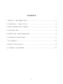
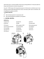
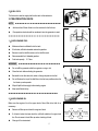
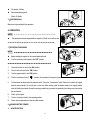
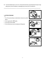
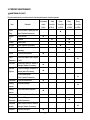
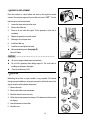
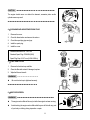
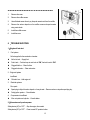
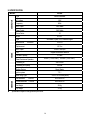
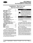
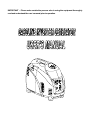
IMPORTANT ─ Please make certain the persons who is using the equipment thoroughly
read and understand the user’s manual prior to operation
CONTENTS
1.SAFETY INFORMATION………………………………………………2
2.CONTROL
FUNCTION……………………………………………3
3.PRE-OPERATION CHECK……………………………………………5
4.OPERATION…………………………………………………………6
5.PERIODIC
MAINTENANCE…………………………………………9
6.TROUBLE SHOOTING………………………………………………12
7.STORAGE…………………………………………………………13
9.SPECIFICATIONS…………………………………………………14
10.WIRING
DIAGRAM…………………………………………………15
1
! WARNING
──────────────────────────────────
PLEASE READ AND UNDERSTAND THIS MANUAL COMPLETELY BEFORE OPERATING THE MACHINE.
────────────────────────────────────────
1.SAFETY INFORMATION
1)EXHAUST FUMES ARE POISONOUS
z
Never operate the engine in a closed area because it may cause unconsciousness and death within a short time.
Operate the engine in a well ventilated area.
2)FUEL IS HIGHLY FLAMMABLE AND POISONOUS
z
Always turn off the engine when refueling
z
Never refuel while smoking or in the vicinity of an open flame.
z
Take care not to spill any fuel on the engine or muffler when refueling.
z
If you swallow any fuel, inhale fuel vapor, or allow any fuel to get in your eyes, see your doctor immediately. If any fuel
spills on your skin or clothing, immediately wash with soap and water and change your clothes.
z
When operating or transporting the machine, be sure it is kept upright. If tilted, fuel may leak from the carburetor or
fuel tank.
3)ENGINE AND MUFFLER MAY BE HOT
z
Place the machine in a place where pedestrians or children are not likely to touch the machine.
z
Avoid placing any flammable materials near the exhaust outlet during operation.
z
Keep the machine at least 1 m ( 3 ft ) from buildings or other equipment, or the engine may overheat.
z
Avoid operating the engine with a dust cover.
z
Be sure to carry the generator only by its handle.
z
Put the machine on a flat surface. This will allow the machine to
hot
distribute the heat evenly.
4)ELECTRIC SHOCK PREVENTION
cool air
z
Never operate the engine in rain or snow.
z
Never touch the machine with wet hands or electrical shock will occur.
z
Be sure to ground (earth) the generator.
The National Electric Code requires that the frame of generator and the
external electrically conductive parts of the generator be connected to an
2
approved earth ground. Local codes may differ and require other grounding specifications. For this purpose, please use
the ground wire that attaches from the frame to the generator unit.
Using a No. 12 AWG (American Wire Gauge) stranded copper wire to the frame and to an earth-driven copper or brass
grounding rod provides sufficient safety against shock. However, local codes may differ. Contact a local electrician to find
out specifications for grounding your generator
5)CONNECTION NOTES
z
Avoid connecting the generator to commercial power outlet.
z
Avoid connecting the generator in parallel with any other generator.
2.CONTROL FUNCTION
DESCRIPTION
(1) Engine switch
(2) Auto throttle
(3) Fuel tank
(4) Spark plug
(5) Muffler
(6) Carrying handle
(7) Choke lever
(8) AC receptacle L14-30R
(9) Ground (earth) terminal
(10) AC receptacle 5-20R GFCI
(11) AC protector 20A
(12) Oil alert light
(13) Overload light
(14) Output light
(15) Fuel filter
(16) Fuel tank cap
(17) Recoil starter
(18) Fuel cock
(19) Oil filler cap
(20) Air filter cover
1
8
2
9
3
4
10 11 12 13 14
5
15
16
19 20
6
7
17
3
18
1)OIL WARNING SYSTEM
When the oil level falls below the low level line, the engine will stop
automatically. Unless you refill with oil, the engine will not start again.
2)ENGINE SWITCH
The engine switch controls the ignition system.
①
“ON”
Ignition circuit is switched on. The engine can be started.
②
“OFF”
Ignition circuit is switched off. The engine will not run.
3)AUTO THROTTLE
When the AUTO THROTTLE switch is turned to “ECO”, the economy control
will adjust the engine speed according to the connected load. The results are
1
better fuel consumption and less noise.
2
4)FUEL TANK CAP AIR VENT KNOB
The fuel tank cap is provided with an air vent knob to stop fuel flow. The air vent
knob must be turned once counterclockwise from the closed position. This will
1
allow fuel to flow to the carburetor and the engine to run.
When the engine is not in use, tigten the air vent knob clockwise until it is
2
OFF
OFF
4
ON
ON
finger-tight to stop fuel flow.
ON
5)FUEL COCK
OFF
The fuel cock is used to supply fuel from the tank to the carburetor.
3. PRE-OPERATION CHECK
NOTE: ─ ─ ─ ─ ─ ─ ─ ─ ─ ─ ─ ─ ─ ─ ─ ─ ─ ─ ─ ─ ─ ─ ─ ─
z
Add more than 2 liters of fuel to run this machine for the first time.
z
Pre-operation checks should be made each time the generator is used.
───────────────────────────
1)CHECK ENGINE FUEL
z
Make sure there is sufficient fuel in the tank.
z
If fuel is low, refill with unleaded automotive gasoline.
z
Be sure to use the fuel filter screen on the fuel filter neck.
z
Recommended fuel: Unleaded gasoline.
z
Fuel tank capacity: 5.7 liters
WARNING: ─ ─ ─ ─ ─ ─ ─ ─ ─ ─ ─ ─ ─ ─ ─ ─ ─ ─ ─ ─ ─ ─
z
Do not refill the generator while the engine is running or hot.
z
Close fuel cock before refueling the generator.
z
Be careful not to allow dust, dirt, water or foreign objects into the fuel.
z
Do not fill above the top of the fuel filter or the fuel may overflow when the
fuel heats up and expands.
z
Wipe off spilt fuel thoroughly before starting engine.
z
Keep open flames away.
──────────────────────────
2)CHECK ENGINE OIL
Make sure the engine oil is at the upper level of the oil filler hole. Add oil as
necessary.
0¡ Cã
z
Remove oil filler cap and check the engine oil level.
z
If oil level is below the lower level line, refill with suitable oil to upper level
line. Do not screw in the oil filler cap when checking oil level.
z
Change oil if contaminated.
5
SAE 10W
or 10W-30
or 10W-40
25¡ C
ã
SAE #20
or 10W-30
or 10W-40
32¡ Fã
SAE #30
or 10W-30
or 10W-40
80¡ Fã
Oil capacity: 0.9 liters
z
Recommended engine oil:
OFF
Above SJ Grade
ON
z
3)GROUND (Earth)
Make sure to ground (earth) the generator.
4. OPERATION
ON
NOTE: ─ ─ ─ ─ ─ ─ ─ ─ ─ ─ ─ ─ ─ ─ ─ ─ ─ ─ ─ ─ ─ ─ ─ ─
z
The generator has been shipped without engine oil. Fill with oil or it will not start.
───────────────────────────
1)STARTING THE ENGINE
NOTE: ─ ─ ─ ─ ─ ─ ─ ─ ─ ─ ─ ─ ─ ─ ─ ─ ─ ─ ─ ─ ─ ─
z
Before starting the engine, do not connect electrical loads.
z
Turn the economy control switch to the “OFF” position.
ON
ENGINE
SWITCH
OFF
─────────────────────────
1.
Open the fuel tank air vent to the “ON” position.
2.
Turn the fuel cock lever to the “ON” position.
3.
Turn the engine switch to the “ON” position
4.
Turn the choke lever to the “│
5.
Pull the starter handle slowly until resistance is felt. This is the “Compression” point. Return the handle to its original
│ ” position. Not necessary if the engine is warm.
position and pull swiftly. Do not fully pull out the rope. After starting, guide the starter handle to its original position
while still holding the handle. Grasp the carrying handle firmly to prevent the generator from falling over when pulling
the recoil starter.
6.
Warm up the engine.
7.
Turn the choke lever back to the operating position.
8.
Warm up the engine without a load for a few minutes.
2)USING ELECTRIC POWER
1. AC APPLICATION
6
(a) Check the AC pilot lamp for proper voltage.
(b) Turn the economy control switch to the “ON” position.
(c) Turn off the switch(es) of the electrical appliance(s) before connecting to
the generator.
(d) Insert the pulg(s) of the electrical appliance(s) into the receptacle(s).
CAUTION: ─ ─ ─ ─ ─ ─ ─ ─ ─ ─ ─ ─ ─ ─ ─ ─ ─ ─ ─ ─ ─
z
Be sure the electrical load is turned off before plugging it in.
z
Be sure the total load is within the generator rated output.
z
Be sure the socket load current is within socket rated current.
z
The AUTO THROTTLE switch must be turned to “HIGH” when using
electric devices that require a large starting current, such as a compressor
or a submergible pump.
──────────────────────────
2.OVERLOAD INDICATOR LIGHT
The overload indicator light comes on when an overload of a connected
electrical device is detected, the inverter unit overheats, or the AC output
voltage rises. The electronic breaker will then activate, stopping power to the
ECO
AUTO
THROTTLE
HIGH
generation in order to protect the generator and any connected electric devices.
The AC pilot light (green) will turn off and the overload indicator light (red) will
turn on, but the engine will not stop running. As the engine overloads the
overload indicator light(red) with turn on. Allowing you to turn off the power too appliances. After twenty seconds the
overload indicator light will turn off and the generator will begin to run again. If the generator is still overloaded the overload
indicator light with turn on once again. If this process happens a total of three times the engine will completely turn off. If so
please follow the following steps
(a)
Turn off any connected electric devices and stop the engine
(b)
Reduce the total wattage of connected electric devices within the application range.
(c)
Check for blockages in the cooling air inlet and around the control unit. If any blockages are found, remove.
(d)
After checking, restart the engine.
CAUTION: ─ ─ ─ ─ ─ ─ ─ ─ ─ ─ ─ ─ ─ ─ ─ ─ ─ ─ ─ ─ ─ ─ ─ ─ ─ ─ ─ ─ ─ ─ ─ ─ ─ ─ ─ ─ ─
z
The generator AC output automatically resets when the engine is stopped and then restarted.
7
z
The overload indicator light may come on for a few seconds at first when using electric devices that require a large
starting current, such as a compressor or a submergible pump. However, this is not a malfunction.
──────────────────────────────────────────
3)STOPPING THE ENGINE
1. Turn off the power switch(s) on electrical loads or disconnect any electric
devices.
2. Turn the engine switch to “OFF” position.
ON
3. Turn the fuel cock lever to “OFF”.
ENGINE
SWITCH
4. Turn the fuel tank cap air vent knob clockwise until it is finger-tight.
OFF
.
8
OFF
OFF
ON
OFF
5. PERIODIC MAINTENANCE
1) MAINTENANCE CHART
Regular maintenance is most important for the best performance and safe operation.
Pre-operation
Item
Remarks
Spark
Check condition, adjust gap and
Plug
clean. Replace if necessary.
Engine
Check oil level
Oil
Replace
Oil filter
Clean oil filter
Air Filter
Clean. Replace if necessary.
Fuel Filter
Clean fuel cock filter. Replace if
Check choke operation
Valve
Check and adjust when engine
Clearance
is cold.
Fuel Line
Check fuel hose for cracks or
damage. Replace if necessary.
Exhaust
Check for leakage. Retighten or
System
replace gasket if necessary
Every
Every
Every
check
1 months
3 months
6 months
12 months
(daily)
or 20 Hr
or 50Hr
or100Hr
or 300Hr
z
z
z
z
z
z
z
necessary
Choke
Initial
z
z
z
z
Check muffler screen.
z
Clean / replace if necessary.
Carburetor Check choke operation
Cooling
z
Check fan damage.
z
system
Starting
Check recoil starter operation.
system
Idle speed
Check and adjust engine idle speed
Fittings /
Check all fittings and fasteners
Fasteners
correct if necessary.
z
z
z
Crankcase Check breather hose for cracks or
breather
damage. Replace if necessary
Generator
Check the pilot lights
z
z
9
2)ENGINE OIL REPLACEMENT
Place the machine on a level surface and warm up the engine for several
minutes. Then stop the engine and turn the fuel cock knob to “OFF””. Turn the
fuel tank cap air vent knob clockwise.
1.
Loosen the screw and remove the cover.
2.
Remove the oil filler cap
3.
Place an oil pan under the engine. Tilt the generator to drain the oil
completely
4.
Replace the generator on a level surface.
5.
Add engine oil to the upper level.
6.
Install the oil filler cap
7.
Install the cover and tighten the screw
z
Recommended engine oil: (see page 5)
Above SJ Grade
CAUTION: ─ ─ ─ ─ ─ ─ ─ ─ ─ ─ ─ ─ ─ ─ ─ ─ ─ ─ ─ ─ ─ ─
z
Be sure no foreign material enters the crankcase.
z
Do not tilt the generator when adding engine oil. This could result in
overfilling and damage to the engine
z
Clean the oil filter every 100hr.
oil filter
3)AIR FILTER
Maintaining the air filter in proper condition is very important. Dirt induced
through improper installation or improperly servicing the air filter will wear out the
engine. Keep the air filter element always clean.
1. Remove the cover.
2. Remove the air filter cover and element.
3. Wash the element in solvent and dry.
4. Oil the element and squeeze out excess oil. The element should be wet but
not dripping.
5. Insert the element into the air filter.
6. Install the cover
10
CAUTION: ─ ─ ─ ─ ─ ─ ─ ─ ─ ─ ─ ─ ─ ─ ─ ─ ─ ─ ─ ─ ─ ─
The engine should never run without the element; excessive piston and/or
cylinder wear may result.
───────────────────────────
4)CLEANING AND ADJUSTING SPARK PLUG
1. Remove the cover.
2. Check for discoloration and remove the carbon.
3. Check the spark plug type and gap.
4. Install the spark plug.
5. Install the cover
Standard electrode color: Tan Color
Standard Spark Plug: CR4HSB (NGK)
Spark Plug Gap: 0.6-0.7 mm (0.024-0.028 in)
5)FUEL TANK FILTER
1. Remove the fuel tank cap and filter.
2. Clean the filter with solvent. If damaged, replace.
3. Wipe the filter and insert it.
! WARNING ─ ─ ─ ─ ─ ─ ─ ─ ─ ─ ─ ─
z
Be sure the tank cap is tightened securely.
─────────────────
6)MUFFLER SCREEN
! WARNING ─ ─ ─ ─ ─ ─ ─ ─ ─ ─ ─ ─ ─ ─ ─ ─ ─ ─ ─ ─ ─
z
The engine and muffler will be very hot after the engine has been running.
z
Avoid touching the engine and muffler while they are still hot with any part
of your body or clothing during inspection or repair.
11
1
──────────────────────────
1.
Remove the cover.
2.
Remove the muffler screen.
3.
Use a flathead screw driver to pry the spark arrester out from the muffler
4.
Remove the carbon deposits on the muffler screen and spark arrester
using a wire brush.
5.
Install the muffler screen.
6.
Install the cover
6.TROUBLE SHOOTING
1)Engine will not start
1. Fuel system
No fuel supplied to the combustion chamber.
z
No fuel in tank….Supply fuel.
z
Fuel in tank….Fuel tank cap air vent knob to “ON”, fuel cock knob to “ON”.
z
Clogged fuel line….Clean fuel line.
z
Clogged carburetor….Clean carburetor.
2.Engine oil system
Insufficient
z
Oil level is low….Add engine oil.
3. Electrical systems
Poor spark
z
Spark plug is dirty with carbon deposit or it may be wet….Remove carbon or wipe the spark plug dry.
z
Faulty ignition system….Consult dealer.
4. Compression is insufficient
z
Worn out piston and cylinder….Consult dealer.
2)Generator won’t produce power
Safety device (AC) to “OFF” …Stop the engine, then restart.
Safety device (DC) to “OFF” …Press to reset DC protector button.
12
7. STORAGE
Long term storage of your machine will require some preventive procedures to guard against deterioration.
1)DRAIN THE FUEL
1.
Remove the fuel tank cap, drain the fuel from the fuel tank
2.
Remove the cover, drain the fuel from the carburetor by loosening the drain screw.
2)ENGINE
1.
Remove the spark plug, pour in about one tablespoon of SAE 10W30 or 20W40 motor oil into the spark plug hole
and reinstall the spark plug.
2.
Use the recoil starter to turn the engine over several times (with ignition off).
3.
pull the recoil starter until you feel compression.
4.
Stop pulling.
5.
Clean exterior of the generator and apply a rust inhibitor.
6.
Store the generator in a dry, well-ventilated place, with a cover placed over it.
7.
The generator must remain in a vertical position.
13
9. SPECIFICATION
MODEL
IN3500i
GENERATOR
Type
AC Voltage
120V
Frequency
60Hz
Max. Output
3500 Watts
Rated Output
3000 Watts
Power Factor
1.0
Model
XY157F
Type
Air-cooled, 4 cycle, OHV, Gasoline Engine
Bore×Stroke
ENGINE
Inverter Generator
mm×mm
57×57.8
Displacement
147.5 cc
Max. Output
4.0KW / 5500rpm
Fuel
Regular Automobile Gasoline
Fuel tank Capacity
5.7 liters
Rated Continuous Operation
3h5min(100% Load) 4h10min(50% Load)
Lubricating oil
SAE 10W30
Lubricating oil Capacity
0.90 liter
Starting System
Recoil Starter
Ignition system
T.C. I.
Spark Plug: Type
DIMENSION
Net dimension
z
A7RTC or CR5HSB (NGK)
L×W×H
565×320×470
Overall dimension L×W×H
595×355×510
Net Weight
29 Kg
Dry Weight
31 Kg
Specifications subject to change without prior notice.
14
10.WIRING DIAGRAM
M
R
O
Y
P
BU
R
O
Y
BL
BU
BL
BL
BL
BL
R
R
BL
BL
BL
BL
BL
BL
W
W
Protector 20A
St eppi ng mot or
Y/ G
Mai n
wi ndi ng
cont r ol
wi ndi ng
W
BL
W
BL
I nver t
cel l
R
Y
BU
O
BL
BL
PU
BL
AC27V wi ndi ng
OI L SENSOR
Spar k
pl ug
W
Y/ G
Economi c
swi t ch
BU Wor ki ng
GR i ndi cat or
W
BU
R
R
A
Over l oad
Y/ G i ndi cat or
P
O
BU Low oi l
i ndi cat or
Spr i ng wi ndi ng
I gni t i on
equi pment
R
Hi gh
pr essur e
wr ap
15
Engi ne
swi t ch
LIMITED WARRANTY
Eastern Tools & Equipment, Inc. will repair or replace, free of charge, any part or parts of the generator that are defective in material or
workmanship or both. Transportation charges on parts submitted for repair or replacement under this Warranty must be borne by
purchaser. This warranty is effective for the time period and subject to the conditions provided for in this policy. For warranty service, find
the nearest Authorized Service Dealer by contacting the place of purchase or Eastern Tools & Equipment, Inc.
THERE IS NO OTHER
EXPRESSED WARRANTY. IMPLIED WARRANTIES, INCLUDING THOSE OF MERCHANTABILITY AND FITNESS FOR A
PARTICULAR PURPOSE, ARE LIMITED TO ONE YEAR FROM PURCHASE, OR TO THE EXTENT PERMITED BY LAW ANY AND
ALL IMPLIED WARRANTIES ARE EXCLUDED. LIABILITY FOR CONSEQUENTIAL DAMAGES UNDER ANY AND ALL
WARRANTIES ARE EXCLUDED TO THE EXTENT EXCLUSION IS PERMITTED BY LAW. Some states do not allow limitations on
how long an implied warranty lasts, and some states do not allow the exclusion or limitation of incidental or consequential damages, so the
above limitation and exclusion may not apply to you. This warranty gives you specific legal rights and you may also have other rights,
which vary from state to state.
Eastern Tools & Equipment, Inc
WARRANTY PERIOD***
WITHIN U.S.A AND CANADA
ENGINES
OUTSIDE U.S.A. AND CANADA
CONSUMER
COMMERCIAL
CONSUMER
COMMERCIAL
USE
USE
USE
USE
1 year
90 days
1 year
90 days
GASOLINE
GENERATOR
The warranty period begins on the date of purchase by the first retail consumer or commercial end user, and continues for the period of time
stated in the table above. “Consumer use” means personal residential household use by a retail consumer. “Commercial use” means all
other uses, including the commercial, income producing or rental purpose. Once the engine has experienced commercial use, it shall
thereafter be considered as a commercial use engine for purpose of this warranty. Engines use in competitive racing or commercial
or rental tracks are not warranted.
16
***A two-year warranty applies to the emission control system on engines certified by EPA and CARB.
IMPORTANT
“WARRANTY REGISTRATIONS IS NECESSARY TO OBTAIN LIMITED WARRANTY ON EASTERN
TOOLS & EQUIPMENT, INC., ENGINES. THE WARRANTY REGISTRATION CARD MUST BE
RETURNED WITHIN 15 DAYS OF PURCHASE FOR LIMITED WARRANTY TO BE VALID”
About Your Product Warranty
Eastern Tools & Equipment, Inc. welcomes warranty repair and apologizes to you for being inconvenienced. Any Authorized Service
Dealer may perform warranty repairs. Most warranty repairs are handled routinely, but sometimes warranty service may be inappropriate.
For example, warranty would not apply if an engine is damaged because of misuse, lack of routine maintenance, shipping, handling,
warehousing and improper installation. Similarly, warranty is void if the serial number on the engine has been removed or if the engine has
been altered or modified. If a customer differs with the decision of the Service Dealer, an investigation will be made to determine whether
the warranty applies. Ask the Service Dealer to submit all supporting facts to his Distributor or the factory for review. If the distributor or
the factory decides that the claim is justified, the customer will be fully reimbursed for those items that are defective.
To avoid
misunderstanding, which might occur between the customer and the dealer, listed below are some of the causes of engine failure that the
warranty does not cover.
Normal wear:
Engines and generators, like all mechanical devices, need periodic parts service and replacement to perform well. Warranty will not cover
repair when normal use has exhausted the life of a part of an engine.
Improper maintenance:
The life of an engine or your equipment depends upon the conditions under which it operates, and the care it receives. Some applications,
such as tillers, pumps, and rotary movers, are very often used in dusty or dirty conditions, which can cause what appears to be premature,
wear. Such wear, when caused by dirt, dust, spark pug cleaning grit, or other abrasive material that has entered the engine because of
improper maintenance is not covered by warranty.
This warranty cover engine related defective material and/or workmanship only, and not replacement or refund of the equipment
to which the engine may be mounted. Nor des the warranty extend to repairs required because of:
1.
Problems caused by parts that are not original eastern tools & equipment, inc., parts.
2.
Equipment controls or installations that prevent starting, cause unsatisfactory engine performance, or shorten engine life.
(Contact equipment manufacturer.)
17
3.
Leaking carburetor, clogged fuel pipes, sticking valves, or other damage, caused by using contaminated or stale fuel.
(Use clean, fresh, lead-free gasoline.)
4.
Parts which are scored or broken because an engine was operated with insufficient or contaminated lubricating oil, or and
incorrect grad of lubricating oil (check oil level daily or after every 8 hours of operation. Refill when necessary and change
at recommended intervals.) Engine damage may occur if oil level is not properly maintained. Read Operating &
Maintenance Instructions.
5.
Repair or adjustment of associated parts or assemblies such as clutches, transmissions, remote controls, etc., which are not
manufactured by Eastern Tools & Equipment, Inc.
6.
Damage or wear to parts caused by dirt, which entered the engine because of improper air filter maintenance, re-assembly,
or use of a non-original air filter element or cartridge. Read Operating & Maintenance Instructions.
7.
Parts damaged by over-speeding, or overheating caused by grass, debris, or dirt, which plugs or clogs the cooling fins, or
flywheel are, or damaged caused by operating the engine in a confined area without sufficient ventilation.
8.
Engine or equipment parts broken by excessive vibration caused by a loosen cutter blades unbalanced blades or loose
unbalanced impellers, improper attachment of equipment to engine crankshaft, over speeding or other abuse in operation.
9.
A bent or broken crankshaft, caused by striking a solid object with the cutter blade of a rotary lawn mower, or excessive
v-belt tightness.
10.
Routine tune-up or adjustment of the engine.
11.
Engine or engine component failure, i.e., combustion chamber, valves, valve seats, valve guides, or burned starter motor
winding, caused by the alternated fuels such as, liquefied petroleum, natural gas, altered gasoline’s etc.
Warranty is available only through service dealers, which have been authorized by Eastern Tools & Equipment, Inc.,
please contact the place of purchase or Eastern Tools & Equipment, Inc. for a Service Dealer near you.
CALIFORNIA & USEPA EMISSION (OR EVAPORATIVE) CONTROL WARRANTY
The U.S. Environmental Protection Agency (EPA), the California Air Resources Board (CARB) and Eastern Tools & Equipment, Inc. are
pleased to explain the Federal and California Emission Control System Warranty on your small non-road engine. In California, new small
nonroad engines must be designed, built and equipped to meet the State’s stringent and anti-smog standards. Eastern Tools &
Equipment, Inc. must warrant the emission (or evaporative) control system on your small nonroad engine for the periods of time listed above
listed above provided there has been no abuse, neglect or improper maintenance of your small nonroad engine.
Your emission (or evaporative) control system may include parts such as the carburetor, or fuel-injection system, the ignition system and
catalytic converter. Also included may be hoses, belts, connectors and other emission (or evaporative)-related assemblies.
Where a warrantable condition exists, Eastern Tools & Equipment, Inc. will repair your small nonroad engine at no cost to you including
diagnosis, parts and labor.
18
OWNER’S WARRANTY RESPONSIBILITIES
As the small nonroad engine owner, you are responsible for the performance of the required maintenance listed in your Owner’s Manual.
Eastern Tools & Equipment, Inc. recommends that you retain all receipts covering maintenance on your small nonroad engine, but Eastern
Tools & Equipment, Inc. cannot deny warranty solely for the lack of receipts or for your failure to ensure the performance of all scheduled
maintenance.
As the small nonroad engine owner, you should, however, be aware that Eastern Tools & Equipment, Inc. may deny you warranty coverage
if your; small nonroad or part thereof has failed due to abuse, neglect, improper maintenance or unapproved modifications.
You are responsible for presenting your small nonroad engine to Eastern Tools & Equipment, Inc. distribution center as soon as a problem
exists. The warranty repairs should be completed in a reasonable amount of time, not to exceed 30 days.
If you have any questions regarding your warranty rights and responsibilities or request warranty service you should contact either the place
of purchase or Eastern Tools & Equipment, Inc., c/o Service Manager, Engine and Equipment Service Division.
IMPORTANT NOTE:
This warranty statement explains your rights and obligations under Emission Control system Warranty (ECS Warranty), which is provided to
our by Eastern Tools & Equipment, Inc. pursuant to California law, Eastern Tools & Equipment, Inc. also provides to original purchasers of
new Eastern Tools & Equipment, Inc. engines. Eastern Tools & Equipment, Inc. Limited Warranties for New engines & other Equipment
associated with the engine (Eastern Tools & Equipment, Inc. Products Warranty), which is enclosed with all New Eastern Tools &
Equipment, Inc. engines and products on a separate sheet. The ECS Warranty applies only to the emission (or evaporative) control
system of your new engine. To the extent that there is any conflict in terms between the ECS Warranty and the Eastern Tools &
Equipment, Inc., Warranty, the ECS Warranty shall apply except in any circumstances in which the Eastern Tools & Equipment, Inc. Product
Warranty may provide a longer warranty period. Both the ECS Warranty and the Eastern Tools & Equipment, Inc. product Warranty
describe important right and obligations with respect to your new engine.
Eastern Tools & Equipment, Inc. at its location in Ontario, California can perform warranty service or any authorized service dealer near you.
At the time of requesting warranty service, evidence must be presented of the date of sale to the original purchaser. The purchaser shall pay
any charges for transporting the product to and from the place when the inspection and/or warranty preformed. The purchaser shall be
responsible for any damage or loss incurred in connection with the transportation of any engine or any part(s) thereof submitted for inspection
and/or warranty work.
If you have any questions regarding your warranty rights and responsibilities, you should contact Eastern Tools & Equipment, Inc.
19
Mail:
Eastern Tools & Equipment, Inc.
111 Bluegrass Dr.
Norwalk, OH 44857
Telephone:
1-888-908-6200
Website:
www.easterntools.com
20
21