1
Epec 4W Herman Installation and Maintenance Manual © Epec Oy 2 / 75 11.8.2009 MAN000508 Epec 4W Herman, Installation and Maintenance Manual VERSION HISTORY Version Date 0.1 11.8.2009 Description New document Epec Oy reserves all rights for improvements without prior notice Epec Oy Tiedekatu 6 FI-60320 Seinäjoki Postiosoite/Postal address PL/P.O.Box 194 FI-60101 Seinäjoki, Finland Puhelin/Phone +358-(0)20-7608 111 Fax +358-(0)20-7608 110 Internet www.epec.fi 3 / 75 11.8.2009 MAN000508 Epec 4W Herman, Installation and Maintenance Manual TABLE OF CONTENTS 1 GENERAL ........................................................................................................................................ 5 1.1 1.2 1.3 1.4 1.5 1.6 1.7 2 4W HERMAN MEASURING DEVICE.............................................................................................. 8 2.1 2.2 2.3 3 Purpose ..................................................................................................................................... 5 Installation and Maintenance Manual ....................................................................................... 5 Explanations of symbols ........................................................................................................... 5 Safety ........................................................................................................................................ 6 Warranty conditions .................................................................................................................. 6 Environmental issues ................................................................................................................ 7 Definitions, terminology and abbreviations ............................................................................... 7 Measuring device configuration ................................................................................................ 8 User rights and maintenance mode .......................................................................................... 8 Allowing operating during maintenance .................................................................................... 9 FIRST INSTALLATION OF A NEW MEASURING DEVICE ......................................................... 11 3.1 Actions before booting the measuring device for the first time ............................................... 11 3.1.1 Connecting Epec control units and wiring ....................................................................... 11 3.1.2 Safety switch .................................................................................................................... 11 3.1.3 Handle buttons and preselection keyboard ..................................................................... 11 3.1.4 Rotator control ................................................................................................................. 11 3.1.5 Pumps .............................................................................................................................. 12 3.1.6 Connecting sensors and actuators .................................................................................. 12 3.2 Actions after first booting of the measuring device ................................................................. 12 3.2.1 Selecting harvester head and options as well as installing software ............................... 12 4 REPLACING HARVESTER HEAD/REINSTALLING MEASURING DEVICE .............................. 16 5 MANAGING OPTIONS .................................................................................................................. 17 5.1 5.2 6 UPDATING MEASURING DEVICE'S SOFTWARE VERSIONS .................................................. 18 6.1 6.2 7 Changing options after the first installation ............................................................................. 17 Printer ...................................................................................................................................... 17 Updating application software and runtime ............................................................................. 18 Updating display unit firmware ................................................................................................ 20 CALIBRATING MEASURING DEVICE AND SETTINGS ............................................................. 21 7.1 Calibration ............................................................................................................................... 21 7.1.1 Length calibration ............................................................................................................ 21 7.1.2 Diameter sensor movement range calibration ................................................................. 23 7.1.3 Diameter curve calibration ............................................................................................... 24 7.1.4 Rotator handle calibration (option) .................................................................................. 26 7.1.5 Rotator valve calibration (option) ..................................................................................... 26 7.1.6 Saw bar movement range calibration .............................................................................. 27 7.2 Settings ................................................................................................................................... 29 7.3 Restoring default settings ....................................................................................................... 29 8 DIAGNOSTICS AND TROUBLESHOOTING ................................................................................ 30 8.1 Error messages ....................................................................................................................... 30 8.2 Display unit diagnostics screens and using them when troubleshooting ................................ 66 8.2.1 I/O and CAN screen ......................................................................................................... 67 8.2.2 Handles ............................................................................................................................ 68 8.2.3 Operating dial................................................................................................................... 69 8.2.4 Sensors ............................................................................................................................ 69 8.2.5 Harvester Head Controls ................................................................................................. 70 Epec Oy reserves all rights for improvements without prior notice Epec Oy Tiedekatu 6 FI-60320 Seinäjoki Postiosoite/Postal address PL/P.O.Box 194 FI-60101 Seinäjoki, Finland Puhelin/Phone +358-(0)20-7608 111 Fax +358-(0)20-7608 110 Internet www.epec.fi 4 / 75 11.8.2009 MAN000508 Epec 4W Herman, Installation and Maintenance Manual 8.2.6 9 Message log..................................................................................................................... 71 REPLACING A FAULTY CONTROL UNIT ................................................................................... 72 9.1 9.2 10 Replacing the head, cabin or hub control unit ........................................................................ 72 Replacing the display unit control unit .................................................................................... 73 CUSTOMER SUPPORT ............................................................................................................. 75 10.1 10.2 Ordering spare parts ........................................................................................................... 75 Contact information and on-call times ................................................................................. 75 Epec Oy reserves all rights for improvements without prior notice Epec Oy Tiedekatu 6 FI-60320 Seinäjoki Postiosoite/Postal address PL/P.O.Box 194 FI-60101 Seinäjoki, Finland Puhelin/Phone +358-(0)20-7608 111 Fax +358-(0)20-7608 110 Internet www.epec.fi 5 / 75 11.8.2009 MAN000508 Epec 4W Herman, Installation and Maintenance Manual 1 GENERAL 1.1 Purpose This Installation and Maintenance Manual is meant for authorised service personnel to be used as an aid when installing and maintaining the 4W Herman measuring device. Do not hand over this document to the device users or any other third parties! 1.2 Installation and Maintenance Manual The measuring device may be installed only by a mechanic authorised by the harvester head manufacturer. A USB M.A.S.K. flash memory drive with at least maintenance-level user rights (= a USB maintenance memory drive) is required when installing the measuring device. The harvester head manufacturer delivers such USB maintenance memory drives only to trained and approved maintenance and installation companies. This is done to ensure that the devices will be properly installed and safe to use, and also to ensure that the devices will be maintained by trained experts. 1.3 Explanations of symbols This manual includes the following symbols to point out important information or safety instructions: The symbol and warning refer to electric shocks that may cause when touching the product or a product component. A failure may endanger the user's health, cause danger to the user or render the system non-functional. This symbol refers to very important information or a warning. If instructions marked with this symbol are not followed, personal injury, a system failure or a software failure will occur. This symbol highlights important information and issues the user must read and take into account when using the product. Epec Oy reserves all rights for improvements without prior notice Epec Oy Tiedekatu 6 FI-60320 Seinäjoki Postiosoite/Postal address PL/P.O.Box 194 FI-60101 Seinäjoki, Finland Puhelin/Phone +358-(0)20-7608 111 Fax +358-(0)20-7608 110 Internet www.epec.fi 6 / 75 11.8.2009 MAN000508 Epec 4W Herman, Installation and Maintenance Manual 1.4 Safety This product is meant to be used as a harvester head measuring and control device only. Using the product for any other purpose is not allowed. The user must follow general safety instructions of the machine, directives, regulations and country-specific statutes. The user must carefully familiarise him or herself with the system features. The system may be installed by trained persons acquainted with the device in accordance with the system Installation and Maintenance Manual. The person installing the system must carry out thorough testing before the system is taken into use. The latest system User Manual must be available in the machine so that the system user will have access to up-to-date information about correct and safe machine control. The system may be maintained by trained persons acquainted with the device in accordance with the system Installation and Maintenance Manual. Control units included in the system cannot be maintained at a logging site and the systems may not be dismantled under any circumstances. The control units may be maintained only by the manufacturer or a person authorised by the manufacturer. Epec Oy reserves the right to make improvements in its products without a prior announcement. 1.5 Warranty conditions Epec offers products and software delivered a twelve (12) month guarantee starting from delivery of the product to the end customer. As the manufacturer, Epec is liable for material, design and manufacturing faults of the control units listed in Section 3.1 and the display unit that arise during the warranty period. The manufacturer may, at its own discretion, either repair a faulty product or replace it with a new one. All warranty repairs the manufacturer chooses to implement will be performed at the manufacturer's plant in Seinäjoki, Finland. The manufacturer's warranty does not cover any cables classified as consumables or any installations done by a retailer or a reseller. The warranty will not cover any costs arising from detachment or fixing of the product or its delivery from and back to the customer, or any travel, accommodation, daily allowance and similar expenses of a mechanic. The manufacturer cannot be held liable for a production shutdown, lost profits, a disturbance in operations or any other indirect damage, regardless of its cause. If the manufacturer is the subject of any claims pertaining to product liability or business liability damage which the manufacturer may be liable to compensate, the manufacturer's liability will be limited and the manufacturer can be held liable only to the extent defined by normal product liability and business liability insurance terms and conditions. The manufacturer's liability for direct damage will be limited in each case to the full value of the products sold. The warranty period of new or used parts installed under the warranty will end when the original warranty period ends. The warranty will become null and void if a reseller, the end user and/or a third party makes any changes to the product or software, or if the product or software is otherwise used contrary to the manufacturer's instructions. Epec Oy reserves all rights for improvements without prior notice Epec Oy Tiedekatu 6 FI-60320 Seinäjoki Postiosoite/Postal address PL/P.O.Box 194 FI-60101 Seinäjoki, Finland Puhelin/Phone +358-(0)20-7608 111 Fax +358-(0)20-7608 110 Internet www.epec.fi 7 / 75 11.8.2009 MAN000508 Epec 4W Herman, Installation and Maintenance Manual A reseller or a mechanic may define separate additional warranties for the product, in addition to the manufacturer's warranty. 1.6 Environmental issues The manufacturer's processes and the materials used are ISO 14001 certified. In the case of products returned by the buyer and/or maintenance work, the manufacturer will recycle and dispose of products found unfit for use. The manufacturer will charge the buyer a waste management fee in accordance with the valid price list. The waste management fee will not be charged if the product is returned under the warranty, however. 1.7 Definitions, terminology and abbreviations A list of definitions, terminology and abbreviations with which the reader may not be familiar. Unnecessary abbreviations may be deleted from the list. • CAN Controller Area network • SDO (Service Data Object) A protocol used to read and write data in the CANopen object library. • PDO (Process Data Object) A protocol used to update process signal status between CANopen nodes and object libraries. • M.A.S.K. (Multi-Access Service Key) A USB memory including the user rights needed when maintaining or installing a 4W Herman measuring device. • Runtime • Firmware Epec Oy reserves all rights for improvements without prior notice Epec Oy Tiedekatu 6 FI-60320 Seinäjoki Postiosoite/Postal address PL/P.O.Box 194 FI-60101 Seinäjoki, Finland Puhelin/Phone +358-(0)20-7608 111 Fax +358-(0)20-7608 110 Internet www.epec.fi 8 / 75 11.8.2009 MAN000508 Epec 4W Herman, Installation and Maintenance Manual 2 4W HERMAN MEASURING DEVICE 2.1 Measuring device configuration The Epec 4W Herman measuring device consists of four control units (= control units) connected to a CAN bus. These are the display, the harvester head, the cabin and the hub. The system also includes the Epec 4W Herman operating dial. Another essential part of the system is the control handles, even though they are not included in the standard measuring device delivery. A printer (Canon IP100) is available as an accessory to the system. Figure 1. Configuration of the 4W Herman measuring device. 2.2 User rights and maintenance mode The measuring device uses the M.A.S.K. system to identify users and define user rights. In practice, this means that there are different kinds of user rights for the measuring device's different settings. There are three user right levels (user, maintenance and factory). The user level has the least extensive access rights and the factory level the most extensive rights. In practice, all users of the measuring device have user-level rights. People to whom the harvester head manufacturer has delivered a USB memory including the maintenance level user rights have maintenance level access. The harvester head manufacturer and measuring device manufacturer have factory level user rights. Epec Oy reserves all rights for improvements without prior notice Epec Oy Tiedekatu 6 FI-60320 Seinäjoki Postiosoite/Postal address PL/P.O.Box 194 FI-60101 Seinäjoki, Finland Puhelin/Phone +358-(0)20-7608 111 Fax +358-(0)20-7608 110 Internet www.epec.fi 9 / 75 11.8.2009 MAN000508 Epec 4W Herman, Installation and Maintenance Manual The different user rights disable certain screens or settings from certain user groups who do not need to see the screens or change the settings. The user rights are specified by the measuring device manufacturer and the harvester head manufacturer. Maintenance mode refers to a situation in which a USB memory with at least maintenance level user rights is connected to the display unit's USB port, which enables installation and changing settings required when maintaining the system. When the device is in the maintenance mode, the top bar of all screens is red. Functions that are prevented when the device is not in the maintenance mode: • Updating software versions using a USB memory • Editing options • Reinstalling the system • Restoring default settings • Changing pump control settings • Viewing/editing some settings Only the harvester head manufacturer is able to generate USB memories with maintenance or factory level user rights. The manufacturer uses special software for this. The user rights cannot be copied from one USB memory to another. DO NOT HAND OVER A USB MEMORY INCLUDING THE USER RIGHTS TO THE MACHINE USERS OR OTHER THIRD PARTIES! 2.3 Allowing operating during maintenance The measuring device requires all the control units for safe operation. This is why all the control units control each others' activity through the CAN bus. If one of the control units malfunctions, the measuring device will enter a so-called safe mode where all control functions are prevented. In some situations, it is important to be able to temporarily control the harvester head so that the machine can be transferred onto a platform for transport, etc. For example, if the display unit is damaged and there is still a log in the harvester head, the harvester head must be opened before the machine can be transported. This is possible even if the display unit has malfunctioned by connecting the hub control unit's maintenance operation input (X4.11) with a jump thread to the ground potential (X4.23); see the following figure. This enables temporary manual control of the harvester head movements but prevents all automatic functions, such as automatic cut-to-length. Maintenance operation can only be allowed when the display unit has malfunctioned; all the other control units and the CAN bus must still be in working order. Epec Oy reserves all rights for improvements without prior notice Epec Oy Tiedekatu 6 FI-60320 Seinäjoki Postiosoite/Postal address PL/P.O.Box 194 FI-60101 Seinäjoki, Finland Puhelin/Phone +358-(0)20-7608 111 Fax +358-(0)20-7608 110 Internet www.epec.fi 10 / 75 11.8.2009 MAN000508 Epec 4W Herman, Installation and Maintenance Manual THE MAINTENANCE OPERATION MODE OVERRIDES SOME OF THE MEASURING DEVICE'S SAFETY FEATURES AND SHOULD ONLY BE USED WHEN IT IS ABSOLUTELY NECESSARY! DON'T FORGET TO DISENGAGE THE MAINTENANCE OPERATION MODE BEFORE LEAVING THE MACHINE! Figure 2. Connections required to enter maintenance operation mode. Epec Oy reserves all rights for improvements without prior notice Epec Oy Tiedekatu 6 FI-60320 Seinäjoki Postiosoite/Postal address PL/P.O.Box 194 FI-60101 Seinäjoki, Finland Puhelin/Phone +358-(0)20-7608 111 Fax +358-(0)20-7608 110 Internet www.epec.fi 11 / 75 11.8.2009 MAN000508 Epec 4W Herman, Installation and Maintenance Manual 3 FIRST INSTALLATION OF A NEW MEASURING DEVICE 3.1 Actions before booting the measuring device for the first time 3.1.1 Connecting Epec control units and wiring See Appendix 1, General Epec Control unit Connection and Installation Manual. 3.1.2 Safety switch For safety reasons, there must be a machine safety switch connected to the measuring device's hub control unit. The safety switch can be a door switch, a seat limit detector or another safety switch. The only limitation is that the switch must generate a 24 V voltage when the operator is seated and the machine is ready to be used. Epec recommends redundant safety switch voltage by, for example, using two safety switches or a safety switch with two sets of poles. The two safety switch voltage messages must be connected with separate conductors to the hub control unit; see the switch diagram (Appendix 2). If using a redundant safety switch is not possible in the base machine in use, the redundancy feature of the measuring device can be disengaged. 3.1.3 Handle buttons and preselection keyboard The system directly supports SureGrip L8 handles and a ten-button preselection keyboard. Handles by other manufacturers may also be used, provided that they have the same number of buttons. The handles must have a total of twenty function buttons and ten preselection buttons. If there are SureGrip L8 handles and a preselection keyboard, connect the handles as shown in the switch diagram (Appendix 2). The measuring device includes programmable function buttons; the function buttons will automatically change based on the selected options, which means that no button wiring changes will be necessary if the selected rotator control method are the handle buttons, for example. 3.1.4 Rotator control 4W Herman supports the following rotator control alternatives: • Rotator control using the base machine with no connection to the measuring device. • Rotator control using the handle buttons with two of the handle buttons being used for rotator control. Epec Oy reserves all rights for improvements without prior notice Epec Oy Tiedekatu 6 FI-60320 Seinäjoki Postiosoite/Postal address PL/P.O.Box 194 FI-60101 Seinäjoki, Finland Puhelin/Phone +358-(0)20-7608 111 Fax +358-(0)20-7608 110 Internet www.epec.fi 12 / 75 11.8.2009 MAN000508 Epec 4W Herman, Installation and Maintenance Manual • Rotator control with a joystick: the right handle (joystick) potentiometer signal for direction x (0–5 V) is connected to the cabin control unit input X3.7. See the switch diagram (Appendix 2). • Rotator control using a hydraulic handle and pressure sensors. If an excavator is used as the base machine, the pressure sensors can be connected to the harvester head cylinder's pilot-operated pressure line, in which case the rotator will be controlled based on the sensor signals (0–5 V). There must be a sensor for both directions, and these sensors must be connected to the seat control unit inputs X3.20 and X3.22. See the switch diagram (Appendix 2). - If controlling the harvester head cylinder in connection with boom extension (jib) control is necessary, a selection valve can be connected to the measuring device to select whether the hydraulics will control the rotator or the harvester head cylinder. See the switch diagram (Appendix 2). The rotator/harvester head cylinder selection valve can be controlled using the handle buttons. 3.1.5 Pumps The 4W Herman measuring device supports simultaneous control of a maximum of three pumps. The pumps may be of the on/off type or proportional pumps. Pump control can be configured separately for each movement. For more information on this function, please see Settings. 3.1.6 Connecting sensors and actuators When connecting the sensors and actuators, the measuring device switch diagram (Appendix 2) and the connection guidelines included in the Epec Control unit Installation and Connection Manual must be followed. 3.2 Actions after first booting of the measuring device 3.2.1 Selecting harvester head and options as well as installing software Epec delivers the display unit with the application installed. The I/O control units do not have an application (or firmware) downloaded which means that a USB memory with maintenance or factory level user rights containing the software package must be connected to the display unit. When you switch on the measuring device for the first time, the first screen will be the harvester head selection screen. Epec Oy reserves all rights for improvements without prior notice Epec Oy Tiedekatu 6 FI-60320 Seinäjoki Postiosoite/Postal address PL/P.O.Box 194 FI-60101 Seinäjoki, Finland Puhelin/Phone +358-(0)20-7608 111 Fax +358-(0)20-7608 110 Internet www.epec.fi 13 / 75 11.8.2009 MAN000508 Epec 4W Herman, Installation and Maintenance Manual Figure 3. The harvester head selection screen. 1. 2. 3. 4. 5. Select the language you want under Language. Set the Date if necessary. Set the Time if necessary. Select either SI units or imperial units under Unit. Select the harvester head type under Harvester Head. Be careful when selecting the harvester head: if you want to change it at a later time, you must first return the measuring device to its default mode, and this means that you will lose all changes you have made to the factory settings. For more information on this issue, see Replacing harvester head. If the harvester head you have installed is not included in the selection list, the software package does not support the harvester head type in question. In such a case, please contact the harvester head manufacturer for further instructions. When you have selected the language, unit and harvester head, you must specify the options to be used. The 'Define options' button will not be displayed until you have selected the harvester head and the unit. Figure 4. Specifying options. Epec Oy reserves all rights for improvements without prior notice Epec Oy Tiedekatu 6 FI-60320 Seinäjoki Postiosoite/Postal address PL/P.O.Box 194 FI-60101 Seinäjoki, Finland Puhelin/Phone +358-(0)20-7608 111 Fax +358-(0)20-7608 110 Internet www.epec.fi 14 / 75 11.8.2009 MAN000508 Epec 4W Herman, Installation and Maintenance Manual When you have selected the harvester head and pressed 'Define options', a screen in which you can define the options will be displayed. The options include: o o o o o whether or not top saw or colour marking has been set how the rotator is controlled the type of rear knives that have been installed, or whether the knives have been replaced with collecting jaws whether or not there is jib control whether or not a stump handling device has been installed Note! Select only the options that are available on the harvester head when you are installing the system. The handle button layout depends on the selected options. When you have specified the options and pressed Start, an Update screen will be displayed. You will install the control unit software at this point. Figure 5. The Update screen. The measuring device will automatically select for updating all control units whose software version is older than the version included in the software package on the USB memory. You can start the update by pressing Update. When the update is completed, a summary screen will be displayed. It states that the update was successful/unsuccessful and requests you to reboot the measuring device by selecting OK. At the same time, the default parameters based on the selected harvester head type will be downloaded to the control units and the button layout complying with the selected options will be implemented. Epec Oy reserves all rights for improvements without prior notice Epec Oy Tiedekatu 6 FI-60320 Seinäjoki Postiosoite/Postal address PL/P.O.Box 194 FI-60101 Seinäjoki, Finland Puhelin/Phone +358-(0)20-7608 111 Fax +358-(0)20-7608 110 Internet www.epec.fi 15 / 75 11.8.2009 MAN000508 Epec 4W Herman, Installation and Maintenance Manual Figure 6. The screen after a successful software update. When the measuring device has rebooted, the main menu will be displayed. You can now continue installing the device. Epec Oy reserves all rights for improvements without prior notice Epec Oy Tiedekatu 6 FI-60320 Seinäjoki Postiosoite/Postal address PL/P.O.Box 194 FI-60101 Seinäjoki, Finland Puhelin/Phone +358-(0)20-7608 111 Fax +358-(0)20-7608 110 Internet www.epec.fi 16 / 75 11.8.2009 MAN000508 Epec 4W Herman, Installation and Maintenance Manual 4 REPLACING HARVESTER HEAD/REINSTALLING MEASURING DEVICE If the harvester head is replaced with a harvester head of a different type (from the same manufacturer) than the harvester head for which the measuring device was configured or if the measuring device is transferred to another base machine with a harvester head of a different type (from the same manufacturer), a reinstallation of the measuring device must be performed. The reinstallation will return the system to the state in which it was before the first installation. This means that you will lose all settings you have made in the system and the default settings of the new harvester head will be implemented. This is the only way possible to replace the harvester head. You should save the work area and output data on a USB memory before reinstallation so that you can continue any unfinished work areas after replacing the harvester head or with the other machine. To reinstall the system, connect a maintenance level USB memory to the display unit, open the Factory settings screen (SettingsFactory settings) and select New installation. Figure 7. The Factory settings screen. The measuring device will reboot itself. When the reboot is finished, the Harvester head selection window will be displayed and you can continue the installation in the same manner as when installing the measuring device for the first time. See Chapter 2. Epec Oy reserves all rights for improvements without prior notice Epec Oy Tiedekatu 6 FI-60320 Seinäjoki Postiosoite/Postal address PL/P.O.Box 194 FI-60101 Seinäjoki, Finland Puhelin/Phone +358-(0)20-7608 111 Fax +358-(0)20-7608 110 Internet www.epec.fi 17 / 75 11.8.2009 MAN000508 Epec 4W Herman, Installation and Maintenance Manual 5 MANAGING OPTIONS 5.1 Changing options after the first installation If you need to make changes in the options after the first installation, such as add a colour marking device or a top saw to the harvester head, you can do this using the Options screen. Note that the handle button layout will change if certain options are taken into use or taken out of use. For example, if you disengage the top saw option, the top saw button will be replaced with another button and some buttons may change places. The button layout which changes based on the selected options enables optimal utilisation of the buttons without wiring changes because no unnecessary buttons will be in use at any time. To change the options, connect a maintenance level USB memory to the display unit and open the Options screen (SettingsOptions). Figure 8. The Options screen. When you exit the screen, the handle button layout will be automatically changed based on the selected options. For more information, please see the option-specific button layouts for SureGrip L8 handles (Appendix 3). 5.2 Printer You can connect a printer to the measuring device for printing production data. The 4W Herman measuring device supports Canon IP90 and IP100 inkjet printers. You can connect the printer with the USB cable included in the measuring device delivery to the display unit's USB port (at the end of a wire). The printer power cable (delivered with the printer) must be connected to the cable set's printer connection using a voltage reducer. For more information, please see the 4W Herman Printer Connection Manual (Appendix 4). Epec Oy reserves all rights for improvements without prior notice Epec Oy Tiedekatu 6 FI-60320 Seinäjoki Postiosoite/Postal address PL/P.O.Box 194 FI-60101 Seinäjoki, Finland Puhelin/Phone +358-(0)20-7608 111 Fax +358-(0)20-7608 110 Internet www.epec.fi 18 / 75 11.8.2009 MAN000508 Epec 4W Herman, Installation and Maintenance Manual 6 UPDATING MEASURING DEVICE'S SOFTWARE VERSIONS Software can be updated in maintenance mode only, i.e. when a USB memory with at least maintenance level user rights is connected to the system. However, you can download software to the spare part control unit from the display unit's memory without an USB maintenance memory drive (see Replacing a faulty control unit). 6.1 Updating application software and runtime Copy the software package into the root directory of the USB maintenance memory drive and ensure that there are no previous packages or other zip files in the root directory. Then connect the memory drive to the display unit's USB port and switch the measuring device on. If the versions on the USB memory drive are more recent than the versions of the display unit, the system will automatically transfer to the Update window. You can also go to the Update screen via the Settings menu. (Settings SoftwareUpdate). Figure 9. The Update screen. The Update screen includes information in two tables. The table on the left shows the system control unit names and the current software and runtime versions. The table on the right shows new file versions found on the USB memory or the display unit memory as well as selection fields. ) The USB symbol in the bottom right hand corner of the screen ( shows that the file source is USB. If the symbol is not visible when a USB maintenance memory drive is connected to the system, the memory drive has not been identified or there is no software package on the memory drive. Restart the measuring device. Epec Oy reserves all rights for improvements without prior notice Epec Oy Tiedekatu 6 FI-60320 Seinäjoki Postiosoite/Postal address PL/P.O.Box 194 FI-60101 Seinäjoki, Finland Puhelin/Phone +358-(0)20-7608 111 Fax +358-(0)20-7608 110 Internet www.epec.fi 19 / 75 11.8.2009 MAN000508 Epec 4W Herman, Installation and Maintenance Manual The measuring device will automatically select the software to be downloaded by ticking the application/runtime to be updated. Then, press the button that will start the download(s) and the system will automatically update the control unit software. The downloaded files will be saved in the display unit's file system, and thus the same software can be reloaded without a USB flash drive when a control unit is replaced, for example. The system informs you of the download status in two ways. The version information of software being downloaded will change to "Loading" for the duration of the download, and as green text "Ready" when the download has been successful or as red text "Failed" if the download was unsuccessful. You can also see the progress of a single download with the download bar at the bottom of the screen which shows the status of the download of a file (when the display control unit software is being downloaded, you will only see the text "Loading"). You will be notified of a successful download. When you select OK, the screen software will reboot. The system will be ready to use once rebooted. Figure 10. The screen after a successful software update. If updating a control unit or the display unit was unsuccessful, you will be notified of this when the display unit reboots (or the system will automatically transfer to the Update screen). Figure 11. The screen after an unsuccessful software update. Epec Oy reserves all rights for improvements without prior notice Epec Oy Tiedekatu 6 FI-60320 Seinäjoki Postiosoite/Postal address PL/P.O.Box 194 FI-60101 Seinäjoki, Finland Puhelin/Phone +358-(0)20-7608 111 Fax +358-(0)20-7608 110 Internet www.epec.fi 20 / 75 11.8.2009 MAN000508 Epec 4W Herman, Installation and Maintenance Manual The display unit software will only be updated if all the control unit downloads were successful. 6.2 Updating display unit firmware Instructions on updating the display unit firmware are always included in the update software delivery. Epec Oy reserves all rights for improvements without prior notice Epec Oy Tiedekatu 6 FI-60320 Seinäjoki Postiosoite/Postal address PL/P.O.Box 194 FI-60101 Seinäjoki, Finland Puhelin/Phone +358-(0)20-7608 111 Fax +358-(0)20-7608 110 Internet www.epec.fi 21 / 75 11.8.2009 MAN000508 Epec 4W Herman, Installation and Maintenance Manual 7 CALIBRATING MEASURING DEVICE AND SETTINGS 7.1 Calibration The contents of the Calibration menu change depending on which options you have selected. For example, if the selected rotator control method is button control, there will be no rotator handle calibration screen in the menu. Figure 12. The Calibration menu. 7.1.1 Length calibration Figure 13. Length calibration. The measuring device includes a tree species specific calibration system, which means that each defined tree species must be separately calibrated. Follow the instructions below to calibrate the length. 1. After felling, select the preselection for the tree species to be calibrated. Epec Oy reserves all rights for improvements without prior notice Epec Oy Tiedekatu 6 FI-60320 Seinäjoki Postiosoite/Postal address PL/P.O.Box 194 FI-60101 Seinäjoki, Finland Puhelin/Phone +358-(0)20-7608 111 Fax +358-(0)20-7608 110 Internet www.epec.fi 22 / 75 11.8.2009 MAN000508 Epec 4W Herman, Installation and Maintenance Manual 2. When the Handling screen is displayed, feed a sufficient length of wood (1–3 metres) starting at the base of the log and then cut the log (the length will be reset). 3. Take the harvester head to the side so that you can safety go to measure the log you just cut. Always activate the safety lock when leaving the cabin. 4. When you have measured the actual log length, open the Length Calibration screen. The length of the last cut log and the tree species will be displayed. Ensure from the bottom edge of the screen that the system has suggested the correct tree species. 5. Adjust the length so that the length of the log which you just measured is displayed and select OK. The display unit will ask whether or not you want to save the calibration; select OK again. Figure 14. Saving length calibration. 6. The display unit will return to the Length Calibration screen. Make sure that the length shown is the value you just saved. If this is not the case, the calibration was unsuccessful, and you must go back to item 1 to cut a new log and recalibrate the system. Epec Oy reserves all rights for improvements without prior notice Epec Oy Tiedekatu 6 FI-60320 Seinäjoki Postiosoite/Postal address PL/P.O.Box 194 FI-60101 Seinäjoki, Finland Puhelin/Phone +358-(0)20-7608 111 Fax +358-(0)20-7608 110 Internet www.epec.fi 23 / 75 11.8.2009 MAN000508 Epec 4W Herman, Installation and Maintenance Manual 7.1.2 Diameter sensor movement range calibration Figure 15. Diameter sensor movement range calibration. The diameter sensor movement range calibration will reset the pulse sensor reading when the harvester head is fully closed or save the pulse sensor reading when the harvester head is fully open. 1. Close the harvester head and wait until the pulse reading is reset. 2. Open the harvester head and wait until the pulse reading is stabilised. 3. Repeat the steps above. 4. When the harvester head is fully open and the pulse reading remains stable, select OK to save the calibration. Epec Oy reserves all rights for improvements without prior notice Epec Oy Tiedekatu 6 FI-60320 Seinäjoki Postiosoite/Postal address PL/P.O.Box 194 FI-60101 Seinäjoki, Finland Puhelin/Phone +358-(0)20-7608 111 Fax +358-(0)20-7608 110 Internet www.epec.fi 24 / 75 11.8.2009 MAN000508 Epec 4W Herman, Installation and Maintenance Manual 7.1.3 Diameter curve calibration The diameter curve is calibrated using the last felled/cut log. When you open the Diameter Curve Calibration screen, the measuring device will calculate points for the last cut log. Correctly performed length calibration and diameter sensor movement range calibrations are required before the diameter curve can be successfully calibrated. 250 = Diameter (in millimetres) at the point shown by the measuring i t 73 = Length (in centimetres) at the log end 4 = number of the log X = Measuring point in use Figure 16. Diameter curve calibration. The measuring points of the latest cut log will be shown, and you can select which points you want to use to create the diameter curve. The diameter curve will be created by the straight lines between the points. Points 1 and 20 are always in use, and if no other points are selected, the curve will be a straight line between these two points. You can check that the curve is correct by measuring the diameter of the log at a position shown by a point. If the measuring result is not the same as the diameter displayed for the measuring point in question, you can adjust the curve by changing the diameter value of the point. Repeat this in the case of all the selected measuring points. Before going to measure the log, take the harvester head to the side and activate the safety lock so that measuring the cut logs will be safe. Always activate the safety lock when leaving the cabin. You can use the Print button ( ) to print a printout of the screen (if a printer has been connected to the system). Print a form and take it with you when you go to measure the log. You can see the measuring points and mark the measuring results at the selected measuring points on the blank fields of the form. When you have measured all the points, return to the cabin and adjust the diameters of the selected measuring points based on the results you have written down. Epec Oy reserves all rights for improvements without prior notice Epec Oy Tiedekatu 6 FI-60320 Seinäjoki Postiosoite/Postal address PL/P.O.Box 194 FI-60101 Seinäjoki, Finland Puhelin/Phone +358-(0)20-7608 111 Fax +358-(0)20-7608 110 Internet www.epec.fi 25 / 75 11.8.2009 MAN000508 Epec 4W Herman, Installation and Maintenance Manual Measuring point number Measuring point in use Log number/length at the log end Diameter at the measuring point included in the curve Actually measured diameter at the measuring point Figure 17. A form printed using the Print feature of the Diameter Calibration screen. If you select Graph ( ), a screen where the diameter curve is shown in a graphical format will be displayed. In the graph, the x axis shows the calibrated pulse sensor movement range in pulses and the y axis shows the same data in millimetres. The graph includes the calibration points (= measuring points) that are in use. You can edit the graph by selecting a calibration point and moving it up or down. You cannot move the point higher or lower than the previous point, however. Thus, the curve must be growing. You can see the selected point and its value in the box in the middle. Figure 18. The diameter curve in a graphical format. Epec Oy reserves all rights for improvements without prior notice Epec Oy Tiedekatu 6 FI-60320 Seinäjoki Postiosoite/Postal address PL/P.O.Box 194 FI-60101 Seinäjoki, Finland Puhelin/Phone +358-(0)20-7608 111 Fax +358-(0)20-7608 110 Internet www.epec.fi 26 / 75 11.8.2009 MAN000508 Epec 4W Herman, Installation and Maintenance Manual 7.1.4 Rotator handle calibration (option) The Rotator Handle Calibration screen is available only when the selected rotator control method is handle control (for more information, see Managing options). To calibrate the rotator handle, turn the handle from one extreme position to the other a couple of times, then centre the handle and press OK. The bar onscreen should move and the middle voltage value should change based on the handle movements. The bar should move in the same direction as the handle. If this is not the case, check the handle connections. The voltage values at both ends of the bar show the handle calibration values which you can save by pressing OK. When you press OK, the handle's current position will be saved as the zero point. Therefore, make sure that you will not accidentally press OK before the handle is in the centre position. Figure 19. Rotator handle calibration. 7.1.5 Rotator valve calibration (option) The Rotator Valve Calibration screen is available only when the selected rotator control valve is proportional valve (for more information, please see Managing options). In addition to on/off valves, the measuring device supports the use of voltage-controlled proportional valves in rotator control. When you adjust a voltage value (when the field is active or black), the rotator will be controlled at the voltage in question when you turn the handle. This way, you can see the impact of voltage changes in the movement speed in real time. First, calibrate the minimum voltage for both directions following the instructions below. Adjust the minimum voltage clockwise at its minimum value (200 mA), move the rotator clockwise by slowly increasing the voltage. When the rotator starts to move, centre the handle and repeat the same for the counter-clockwise minimum voltage. The minimum voltage should be the lowest voltage at which the rotator moves. Epec Oy reserves all rights for improvements without prior notice Epec Oy Tiedekatu 6 FI-60320 Seinäjoki Postiosoite/Postal address PL/P.O.Box 194 FI-60101 Seinäjoki, Finland Puhelin/Phone +358-(0)20-7608 111 Fax +358-(0)20-7608 110 Internet www.epec.fi 27 / 75 11.8.2009 MAN000508 Epec 4W Herman, Installation and Maintenance Manual Next, calibrate the maximum voltages as follows: Adjust the clockwise maximum voltage to as low a value as possible (1 mA higher than the minimum voltage you previously calibrated), then move the rotator clockwise by slowly increasing the voltage until the rotator moves at the speed you want to be the maximum movement speed. Repeat the same for counter-clockwise. The maximum voltage may be a maximum of 1,000 mA. When calibrating the rotator (the maximum voltages in particular) take care not to allow the rotator to rotate for a too long a time because this may damage the harvester head's hydraulic hoses. Figure 20. Rotator valve calibration. 7.1.6 Saw bar movement range calibration Saw bar movement range calibration is done in two stages. First, calibrate the bar minimum position (against the tree surface) and then calibrate the bar's maximum position (against the mechanical limit). Depending on the harvester head model, the saw chain will not be rotated during the calibration, it will be rotated only for a short time when the bar moves out of the housing, or it will be rotated during the entire calibration sequence. If you are not sure whether or not chain rotation will be active during calibration, you should remove the chain before calibrating. When you remove or attach the saw chain, the engine may not be running! 1. To calibrate the bar movement range, pick up a tree and press the Saw button until the saw bar touches the surface of the tree. The pulse reading at this point will be saved as the minimum value. Epec Oy reserves all rights for improvements without prior notice Epec Oy Tiedekatu 6 FI-60320 Seinäjoki Postiosoite/Postal address PL/P.O.Box 194 FI-60101 Seinäjoki, Finland Puhelin/Phone +358-(0)20-7608 111 Fax +358-(0)20-7608 110 Internet www.epec.fi 28 / 75 11.8.2009 MAN000508 Epec 4W Herman, Installation and Maintenance Manual Figure 21. Minimum pulse calibration. 2. Then drop the log and press the Saw button until the saw bar has come fully out against the mechanical limit. The pulse reading at this point will be saved as the maximum value. Figure 22. Maximum pulse calibration. 3. Now, you can release the Saw button and press OK to save the calibration. Epec Oy reserves all rights for improvements without prior notice Epec Oy Tiedekatu 6 FI-60320 Seinäjoki Postiosoite/Postal address PL/P.O.Box 194 FI-60101 Seinäjoki, Finland Puhelin/Phone +358-(0)20-7608 111 Fax +358-(0)20-7608 110 Internet www.epec.fi 29 / 75 11.8.2009 MAN000508 Epec 4W Herman, Installation and Maintenance Manual Figure 23. The screen asking whether or not you want to save the new values. 4. If you detached the saw chain when starting calibration, you can now switch off the engine and reattach the chain. After this, you can continue working normally. 7.2 Settings Figure 24. Settings menu. 7.3 Restoring default settings Default settings or factory settings are harvester head specific default settings set by the harvester head manufacturer. If you restore the factory settings, your work area, production and preselection data will not be reset. You can restore the factory settings only when a USB maintenance memory drive is connected to the display unit. To restore the factory settings, go to the Factory Settings screen (SettingsFactory Settings) and select Default parameters. Figure 25. The Factory Settings screen. Epec Oy reserves all rights for improvements without prior notice Epec Oy Tiedekatu 6 FI-60320 Seinäjoki Postiosoite/Postal address PL/P.O.Box 194 FI-60101 Seinäjoki, Finland Puhelin/Phone +358-(0)20-7608 111 Fax +358-(0)20-7608 110 Internet www.epec.fi 30 / 75 11.8.2009 MAN000508 Epec 4W Herman, Installation and Maintenance Manual 8 DIAGNOSTICS AND TROUBLESHOOTING 8.1 Error messages Below is a table listing all the system error messages and other messages. The figure below shows what the table includes. Mess t No. Message x x Description Instructions 1. Instruction 1 2. Instruction 2 n. Instruction n Figure 26. A model of the error message table contents. How to read the table: - The No. field shows the message's unique number for the control unit in question. The messages for each control unit are numbered, starting from zero. - The Message field shows which text will be shown on the Handling screen/the log. The message may slightly differ from the one shown in the table, depending on the language/software version. The crosses to the right of the message field in the table show whether the message will be shown on the Handling screen and/or whether it will be saved in the log. - The Description field explains what the message means and how it influences the measuring device. - The Instructions field shows what actions must be done to locate/correct the fault when maintaining the system and in which order the fault should be located/corrected. The stages are numbered. If you are not able to locate/correct the fault by following the first stage instructions, go to the second one, etc. When you have located/corrected the fault, you do not need to go to the next stage. Epec Oy reserves all rights for improvements without prior notice Epec Oy Tiedekatu 6 FI-60320 Seinäjoki Postiosoite/Postal address PL/P.O.Box 194 FI-60101 Seinäjoki, Finland Puhelin/Phone +358-(0)20-7608 111 Fax +358-(0)20-7608 110 Internet www.epec.fi 31 / 75 11.8.2009 MAN000508 Epec 4W Herman, Installation and Maintenance Manual Harvester head control unit messages/error messages: 0 Alarm number error x Alarm numbering error Contact the measuring device supplier. 1 Control unit booting x The control unit is booting. No measures are necessary. 2 Wrong node ID x x The control unit ID is incorrect. 1. Ensure that the control unit ID pin has been connected as shown in the switch diagram, change the connection if necessary and reboot the system. 2. Ensure that the correct control unit application has been loaded. 3. Replace the control unit. 3 Program cycle length too long x x The program cycle length exceeds the set limit. The cycle length may exceed the set limit when the system is booted; this is normal and no measures are necessary. If the error message is repeatedly issued when working (several times a day), contact the measuring device supplier. 4 CAN message buffer full x x The message buffer for outgoing control unit messages is full and the bus is busy. 1. Check the condition of the CAN bus cables and connectors, and replace them if necessary. 2. Replace the control unit. 3. Contact the measuring device supplier. 5 Erroneous CAN bus messages x x The control unit has received erroneous CAN messages. 1. Check the condition of the CAN bus cables and connectors, and replace them if necessary. 2. Replace the control unit. 3. Contact the measuring device supplier. 6 Low supply voltage x Epec Oy reserves all rights for improvements without prior notice Epec Oy Tiedekatu 6 FI-60320 Seinäjoki Postiosoite/Postal address PL/P.O.Box 194 FI-60101 Seinäjoki, Finland Puhelin/Phone +358-(0)20-7608 111 Fax +358-(0)20-7608 110 Internet www.epec.fi x 32 / 75 11.8.2009 MAN000508 Epec 4W Herman, Installation and Maintenance Manual The control unit supply voltage is low, less than 12 V control functions are prevented. 1. Check the power source voltage and recharge the power source or replace it if necessary. 2. Check the condition of the supply voltage wiring and connectors, and replace them if necessary. 3. Check the control unit's voltage output connections for short-circuits, repair if necessary. 4. Replace the control unit. 7 Low temperature x x The control unit's internal temperature has fallen below the allowed limit, i.e. it is less than -30°C (-22°F). 1. If the outdoor temperature is below -30°C (-22°F), using the measuring device is not allowed. 2. If the outdoor temperature is clearly above -30°C (-22°F), replace the control unit. 8 High temperature x x The control unit's internal temperature has exceeded the allowed limit, i.e. it is more than +70°C (+158°F). 1. If the ambient temperature in the immediate vicinity of the control unit (= on the outer surface of the control unit) is more than +50°C (122°F), the measuring device cannot be used. (Do not place the control unit in a place where the ambient temperature may increase too much, such as in the immediate vicinity of the engine or the hydraulic valves). Move the control unit to another place or ensure that sufficient cooling air is available. 2. If the outdoor temperature is clearly below +50℃ (+122° F), replace the control unit. 11 High supply voltage x x The control unit's supply voltage has exceeded the allowed limit, i.e. it is more than 30 V. 1. Check the power source voltage (while the machine is in operation) and correct it if necessary. 2. Replace the control unit. 12 Start message sent x The control unit has sent an NMT start message to the other system control units. Only the hub control unit can send NMT start messages; contact the measuring device supplier. Epec Oy reserves all rights for improvements without prior notice Epec Oy Tiedekatu 6 FI-60320 Seinäjoki Postiosoite/Postal address PL/P.O.Box 194 FI-60101 Seinäjoki, Finland Puhelin/Phone +358-(0)20-7608 111 Fax +358-(0)20-7608 110 Internet www.epec.fi x 33 / 75 11.8.2009 MAN000508 Epec 4W Herman, Installation and Maintenance Manual 16 Cabin control unit missing x x The connection to the cabin control unit has been disconnected. 1. Check the condition of the CAN bus/supply voltage cables and connectors in between the hub control unit and the cabin control unit, and replace them if necessary. 2. Check the condition of the CAN bus/supply voltage cables and connectors in between the hub control unit and the harvester head control unit, and replace them if necessary. 3. Ensure that the cabin control unit's application software is up-to-date, and update it if necessary. 4. Check the cabin control unit identification pin connection and repair it if necessary. 5. Replace the cabin control unit. 17 Hub control unit missing x x The connection to the hub control unit has been disconnected. 1. Check the condition of the CAN bus/supply voltage cables and connectors in between the hub control unit and the harvester head control unit, and replace them if necessary. 2. Ensure that the hub control unit's application software/runtime is up-to-date, and update it if necessary. 3. Check the hub control unit identification pin connection and repair it if necessary. 4. Replace the hub control unit. 24 Short-circuit, front knives pressure control x x The front knives' pressure control output X1/9 has short-circuited at FB input X1/4. 1. Check the pressure control valve connection, the condition of wiring/connectors, and replace them if necessary. 2. Check the valve impedance and replace the valve if necessary. 3. Check the valve's coil resistance parameter value in the measuring device settings and change it if necessary. 4. Replace the control unit. 25 Disconnected circuit, front knives pressure control x The front knives' pressure control circuit between output X1/9 and FB input X1/4 has been disconnected. 1. Check the pressure control valve connection, the condition of Epec Oy reserves all rights for improvements without prior notice Epec Oy Tiedekatu 6 FI-60320 Seinäjoki Postiosoite/Postal address PL/P.O.Box 194 FI-60101 Seinäjoki, Finland Puhelin/Phone +358-(0)20-7608 111 Fax +358-(0)20-7608 110 Internet www.epec.fi x 34 / 75 11.8.2009 MAN000508 Epec 4W Herman, Installation and Maintenance Manual wiring/connectors, and replace them if necessary. 2. Check the valve coil resistance and replace the valve if necessary. 3. Check the valve's coil resistance parameter value in the measuring device settings and change it if necessary. 4. Replace the control unit. 26 FB input live without control, front knives pressure control x x The front knives' voltage feedback coupling connection at input X1/4 is live when the valve control is not active. One of the valve connectors has short-circuited. 1. Check the pressure control valve connection, the condition of wiring/connectors, and replace them if necessary. 2. Replace the control unit. 27 Short-circuit, front knives open x x The front knives open output X1/1 has short-circuited with the ground potential. 1. Check the valve connection, the condition of wiring/connectors, and replace them if necessary. 2. Check the valve impedance and replace the valve if necessary. 3. Replace the valve cap. (If it is an LED valve cap.) 4. Replace the control unit. 28 Voltage without control, front knives open x x The front knives open output X1/1 is live even though the output is not being controlled. One of the valve connectors has short-circuited. 1. Check the valve connection, the condition of wiring/connectors, and replace them if necessary. 2. Replace the control unit. 29 Short-circuit, front knives closed x x The front knives closed output X1/2 has short-circuited with the ground potential. 1. Check the valve connection, the condition of wiring/connectors, and replace them if necessary. 2. Check the valve impedance and replace the valve if necessary. 3. Replace the valve cap. (If it is an LED valve cap.) 4. Replace the control unit. 30 Voltage without control, front knives closed x Epec Oy reserves all rights for improvements without prior notice Epec Oy Tiedekatu 6 FI-60320 Seinäjoki Postiosoite/Postal address PL/P.O.Box 194 FI-60101 Seinäjoki, Finland Puhelin/Phone +358-(0)20-7608 111 Fax +358-(0)20-7608 110 Internet www.epec.fi x 35 / 75 11.8.2009 MAN000508 Epec 4W Herman, Installation and Maintenance Manual The front knives closed output X1/2 is live even though the output is not being controlled. One of the valve connectors has short-circuited. 1. Check the valve connection, the condition of wiring/connectors, and replace them if necessary. 2. Replace the control unit. 31 Short-circuit, rear knives pressure control x x The rear knives' pressure control output X1/15 has short-circuited at FB input X1/6. 1. Check the pressure control valve connection, the condition of wiring/connectors, and replace them if necessary. 2. Check the valve impedance and replace the valve if necessary. 3. Check the valve's coil resistance parameter value in the measuring device settings and change it if necessary. 4. Replace the control unit. 32 Disconnected circuit, rear knives pressure control x x The rear knives' pressure control circuit between output X1/15 and FB input X1/6 has been disconnected. 1. Check the pressure control valve connection, the condition of wiring/connectors, and replace them if necessary. 2. Check the valve impedance and replace the valve if necessary. 3. Check the valve's coil resistance parameter value in the measuring device settings and change it if necessary. 4. Replace the control unit. 33 FB input live without control, rear knives pressure control x x The rear knives' voltage feedback coupling connection at input X1/6 is live when the valve control is not active. One of the valve connectors has short-circuited. 1. Check the pressure control valve connection, the condition of wiring/connectors, and replace them if necessary. 2. Replace the control unit. 34 Short-circuit, rear knives open x x The rear knives open output X1/7 has short-circuited with the ground potential. 1. Check the valve connection, the condition of wiring/connectors, and replace them if necessary. 2. Check the valve impedance and replace the valve if necessary. Epec Oy reserves all rights for improvements without prior notice Epec Oy Tiedekatu 6 FI-60320 Seinäjoki Postiosoite/Postal address PL/P.O.Box 194 FI-60101 Seinäjoki, Finland Puhelin/Phone +358-(0)20-7608 111 Fax +358-(0)20-7608 110 Internet www.epec.fi 36 / 75 11.8.2009 MAN000508 Epec 4W Herman, Installation and Maintenance Manual 3. Replace the valve cap. (If it is an LED valve cap.) 4. Replace the control unit. 35 Voltage without control, rear knives open x x The rear knives open output X1/7 is live even though the output is not being controlled. One of the valve connectors is broken or has short-circuited. 1. Check the valve connection, the condition of wiring/connectors, and replace them if necessary. 2. Replace the control unit. 36 Short-circuit, rear knives closed x x The rear knives closed output X1/8 has short-circuited with the ground potential. 1. Check the valve connection, the condition of wiring/connectors, and replace them if necessary. 2. Check the valve impedance and replace the valve if necessary. 3. Replace the valve cap. (If it is an LED valve cap.) 4. Replace the control unit. 37 Voltage without control, rear knives closed x x The rear knives closed output X1/8 is live even though the output is not being controlled. One of the valve connectors is broken or has short-circuited. 1. Check the valve connection, the condition of wiring/connectors, and replace them if necessary. 2. Replace the control unit. 38 Short-circuit, tracks pressure control x x The tracks' pressure control output X1/23 has short-circuited at FB input X1/21. 1. Check the track pressure control valve connection, the condition of wiring/connectors, and replace them if necessary. 2. Check the valve coil resistance and replace the valve if necessary. 3. Check the valve's coil resistance parameter value in the measuring device settings and change it if necessary. 4. Replace the control unit. 39 Disconnected circuit, tracks pressure control x The tracks' pressure control circuit between output X1/23 and FB input X1/21 has been disconnected. 1. Check the track pressure control valve connection, the condition of Epec Oy reserves all rights for improvements without prior notice Epec Oy Tiedekatu 6 FI-60320 Seinäjoki Postiosoite/Postal address PL/P.O.Box 194 FI-60101 Seinäjoki, Finland Puhelin/Phone +358-(0)20-7608 111 Fax +358-(0)20-7608 110 Internet www.epec.fi x 37 / 75 11.8.2009 MAN000508 Epec 4W Herman, Installation and Maintenance Manual wiring/connectors, and replace them if necessary. 2. Check the valve coil resistance and replace the valve if necessary. 3. Check the valve's coil resistance parameter value in the measuring device settings and change it if necessary. 4. Replace the control unit. 40 FB input live without control, tracks pressure control x x The tracks' voltage feedback coupling connection at input X1/21 is live when the valve control is not active. One of the valve connectors has short-circuited. 1. Check the rear tracks' pressure control valve connection, the condition of wiring/connectors, and replace them if necessary. 2. Replace the control unit. 41 Short-circuit, tracks open x x The tracks open output X1/19 has short-circuited with the ground potential. 1. Check the valve connection, the condition of wiring/connectors, and replace them if necessary. 2. Check the valve impedance and replace the valve if necessary. 3. Replace the valve cap. (If it is an LED valve cap.) 4. Replace the control unit. 42 Voltage without control, tracks open x x The tracks open output X1/19 is live even though the output is not being controlled. One of the valve connectors has short-circuited. 1. Check the valve connection, the condition of wiring/connectors, and replace them if necessary. 2. Replace the control unit. 43 Short-circuit, tracks closed x x The tracks closed output X1/18 has short-circuited with the ground potential. 1. Check the valve connection, the condition of wiring/connectors, and replace them if necessary. 2. Check the valve impedance and replace the valve if necessary. 3. Replace the valve cap. (If it is an LED valve cap.) 4. Replace the control unit. 44 Voltage without control, tracks closed x Epec Oy reserves all rights for improvements without prior notice Epec Oy Tiedekatu 6 FI-60320 Seinäjoki Postiosoite/Postal address PL/P.O.Box 194 FI-60101 Seinäjoki, Finland Puhelin/Phone +358-(0)20-7608 111 Fax +358-(0)20-7608 110 Internet www.epec.fi x 38 / 75 11.8.2009 MAN000508 Epec 4W Herman, Installation and Maintenance Manual The tracks closed output X1/18 is live even though the output is not being controlled. One of the valve connectors has short-circuited. 1. Check the valve connection, the condition of wiring/connectors, and replace them if necessary. 2. Replace the control unit. 45 Short-circuit, feed forward 1 x x The feed forward 1 output X1/1 has short-circuited with the ground potential. 1. Check the valve connection, the condition of wiring/connectors, and replace them if necessary. 2. Check the valve impedance and replace the valve if necessary. 3. Replace the valve cap. (If it is an LED valve cap.) 4. Replace the control unit. 46 Voltage without control, feed forward 1 x x The feed forward 1 output X1/11 is live even though the output is not being controlled. One of the valve connectors is broken or has short-circuited. 1. Check the valve connection, the condition of wiring/connectors, and replace them if necessary. 2. Replace the control unit. 47 Short-circuit, saw motor x x The saw motor output X1/16 has short-circuited with the ground potential. 1. Check the valve connection, the condition of wiring/connectors, and replace them if necessary. 2. Check the valve impedance and replace the valve if necessary. 3. Replace the valve cap. (If it is an LED valve cap.) 4. Replace the control unit. 48 Voltage without control, saw motor x x The saw motor output X2/16 is live even though the output is not being controlled. One of the valve connectors is broken or has short-circuited. 1. Check the valve connection, the condition of wiring/connectors, and replace them if necessary. 2. Replace the control unit. 49 Short-circuit, saw bar out x Epec Oy reserves all rights for improvements without prior notice Epec Oy Tiedekatu 6 FI-60320 Seinäjoki Postiosoite/Postal address PL/P.O.Box 194 FI-60101 Seinäjoki, Finland Puhelin/Phone +358-(0)20-7608 111 Fax +358-(0)20-7608 110 Internet www.epec.fi x 39 / 75 11.8.2009 MAN000508 Epec 4W Herman, Installation and Maintenance Manual The saw bar out output X2/11 has short-circuited with the ground potential. 1. Check the valve connection, the condition of wiring/connectors, and replace them if necessary. 2. Check the valve impedance and replace the valve if necessary. 3. Replace the valve cap. (If it is an LED valve cap.) 4. Replace the control unit. 50 Voltage without control, saw bar out x x The saw bar out output X2/11 is live even though the output is not being controlled. One of the valve connectors is broken or has short-circuited. 1. Check the valve connection, the condition of wiring/connectors, and replace them if necessary. 2. Replace the control unit. 51 Short-circuit, top saw out x x The top saw out output X2/23 has short-circuited with the ground potential. 1. Check the valve connection, the condition of wiring/connectors, and replace them if necessary. 2. Check the valve impedance and replace the valve if necessary. 3. Replace the valve cap. (If it is an LED valve cap.) 4. Replace the control unit. 52 Voltage without control, top saw out x x The top saw out output X2/23 is live even though the output is not being controlled. One of the valve connectors is broken or has short-circuited. 1. Check the valve connection, the condition of wiring/connectors, and replace them if necessary. 2. Replace the control unit. 53 Short-circuit, feed forward 2 x x The feed forward 2 output X2/13 has short-circuited with the ground potential. 1. Check the valve connection, the condition of wiring/connectors, and replace them if necessary. 2. Check the valve impedance and replace the valve if necessary. 3. Replace the valve cap. (If it is an LED valve cap.) 4. Replace the control unit. Epec Oy reserves all rights for improvements without prior notice Epec Oy Tiedekatu 6 FI-60320 Seinäjoki Postiosoite/Postal address PL/P.O.Box 194 FI-60101 Seinäjoki, Finland Puhelin/Phone +358-(0)20-7608 111 Fax +358-(0)20-7608 110 Internet www.epec.fi 40 / 75 11.8.2009 MAN000508 Epec 4W Herman, Installation and Maintenance Manual 54 Voltage without control, feed forward 2 x x The feed forward 2 output X2/13 is live even though the output is not being controlled. One of the valve connectors is broken or has short-circuited. 1. Check the valve connection, the condition of wiring/connectors, and replace them if necessary. 2. Replace the control unit. 55 Short-circuit, feed forward 3 x x The feed forward 3 output X2/15 has short-circuited with the ground potential. 1. Check the valve connection, the condition of wiring/connectors, and replace them if necessary. 2. Check the valve impedance and replace the valve if necessary. 3. Replace the valve cap. (If it is an LED valve cap.) 4. Replace the control unit. 56 Voltage without control, feed forward 3 x x The feed forward 3 output X2/15 is live even though the output is not being controlled. One of the valve connectors is broken or has short-circuited. 1. Check the valve connection, the condition of wiring/connectors, and replace them if necessary. 2. Replace the control unit. 57 Short-circuit, tilt up x x The tilt up output X1/7 has short-circuited with the ground potential. 1. Check the valve connection, the condition of wiring/connectors, and replace them if necessary. 2. Check the valve impedance and replace the valve if necessary. 3. Replace the valve cap. (If it is an LED valve cap.) 4. Replace the control unit. 58 Voltage without control, tilt up x x The tilt up output X2/7 is live even though the output is not being controlled. One of the valve connectors is broken or has short-circuited. 1. Check the valve connection, the condition of wiring/connectors, and replace them if necessary. 2. Replace the control unit. Epec Oy reserves all rights for improvements without prior notice Epec Oy Tiedekatu 6 FI-60320 Seinäjoki Postiosoite/Postal address PL/P.O.Box 194 FI-60101 Seinäjoki, Finland Puhelin/Phone +358-(0)20-7608 111 Fax +358-(0)20-7608 110 Internet www.epec.fi 41 / 75 11.8.2009 MAN000508 Epec 4W Herman, Installation and Maintenance Manual 59 Short-circuit, tilt down x x The tilt down output X1/8 has short-circuited with the ground potential. 1. Check the valve connection, the condition of wiring/connectors, and replace them if necessary. 2. Check the valve impedance and replace the valve if necessary. 3. Replace the valve cap. (If it is an LED valve cap.) 4. Replace the control unit. 60 Voltage without control, tilt down x x The tilt down output X2/8 is live even though the output is not being controlled. One of the valve connectors is broken or has short-circuited. 1. Check the valve connection, the condition of wiring/connectors, and replace them if necessary. 2. Replace the control unit. 61 Short-circuit, feed backward 1 x x The feed backward 1 output X1/13 has short-circuited with the ground potential. 1. Check the valve connection, the condition of wiring/connectors, and replace them if necessary. 2. Check the valve impedance and replace the valve if necessary. 3. Replace the valve cap. (If it is an LED valve cap.) 4. Replace the control unit. 62 Voltage without control, feed backward 1 x x The feed backward 1 output X1/13 is live even though the output is not being controlled. One of the valve connectors is broken or has short-circuited. 1. Check the valve connection, the condition of wiring/connectors, and replace them if necessary. 2. Replace the control unit. 63 FB input live without control, rotator x x The rotator voltage feedback coupling connection inputs X2/3 and X2/4 are live even though valve control is not active. Some of the valve connectors of one of the rotator valves has short-circuited. 1. Check the valve connections, the condition of wiring/connectors, and replace them if necessary. 2. Replace the control unit. Epec Oy reserves all rights for improvements without prior notice Epec Oy Tiedekatu 6 FI-60320 Seinäjoki Postiosoite/Postal address PL/P.O.Box 194 FI-60101 Seinäjoki, Finland Puhelin/Phone +358-(0)20-7608 111 Fax +358-(0)20-7608 110 Internet www.epec.fi 42 / 75 11.8.2009 MAN000508 Epec 4W Herman, Installation and Maintenance Manual 64 Short-circuit, rotator x x Rotator output X2/1 or X2/2 has short-circuited with FB input X2/3 or X2/4. Find out which of the directional circuits is faulty by controlling the rotator in both directions. The circuit you are controlling when you receive the error message is the one that is faulty. 1. Check the faulty circuit's valve connection, the condition of wiring/connectors, and replace them if necessary. 2. Check the valve impedance and replace the valve if necessary. 3. Check the valve's coil resistance parameter value in the measuring device settings and change it if necessary. 4. Replace the control unit. 65 Parameter error, rotator x x There are conflicting rotator current regulator parameters, or the parameter value is not within the allowed range. 1. Check the valve calibration and recalibrate them is necessary. 2. Check the rotator parameters in the measuring device settings and change them if necessary (coil resistance, ramps, ramp type, alarm delay). 3. Contact the measuring device supplier. 66 Parameter error, front knives pressure control x x There are conflicting front knives' pressure control current regulator parameters, or the parameter value is not within the allowed range. 1. Check the pressure control current settings and pressure curve, and adjust them if necessary. 2. Check the front knives' pressure control parameters in the measuring device settings and change them if necessary (coil resistance, ramps, ramp type, alarm delay). 3. Contact the measuring device supplier. 67 Parameter error, rear knives pressure control x x There are conflicting rear knives' pressure control current regulator parameters, or the parameter value is not within the allowed range. 1. Check the pressure control current settings and pressure curve, and adjust them if necessary. 2. Check the rear knives' pressure control parameters in the measuring device settings and change them if necessary (coil resistance, ramps, ramp type, alarm delay). Epec Oy reserves all rights for improvements without prior notice Epec Oy Tiedekatu 6 FI-60320 Seinäjoki Postiosoite/Postal address PL/P.O.Box 194 FI-60101 Seinäjoki, Finland Puhelin/Phone +358-(0)20-7608 111 Fax +358-(0)20-7608 110 Internet www.epec.fi 43 / 75 11.8.2009 MAN000508 Epec 4W Herman, Installation and Maintenance Manual 3. Contact the measuring device supplier. 68 Parameter error, tracks pressure control x x There are conflicting tracks' pressure control current regulator parameters, or the parameter value is not within the allowed range. 1. Check the pressure control current settings and pressure curve, and adjust them if necessary. 2. Check the tracks' pressure control parameters in the measuring device settings and change them if necessary (coil resistance, ramps, ramp type, alarm delay). 3. Contact the measuring device supplier. 69 Short-circuit, colour marking 1 x x The colour marking 1 output X2/23 has short-circuited with the ground potential. 1. Check the valve connection, the condition of wiring/connectors, and replace them if necessary. 2. Check the valve impedance and replace the valve if necessary. 3. Replace the valve cap. (If it is an LED valve cap.) 4. Replace the control unit. 70 Voltage without control, colour marking 1 x x The colour marking output X2/23 is live even though the output is not being controlled. One of the valve connectors is broken or has short-circuited. 1. Check the valve connection, the condition of wiring/connectors, and replace them if necessary. 2. Replace the control unit. 71 Short-circuit, colour marking 2 x x The colour marking 2 output X2/19 has short-circuited with the ground potential. 1. Check the valve connection, the condition of wiring/connectors, and replace them if necessary. 2. Check the valve impedance and replace the valve if necessary. 3. Replace the valve cap. (If it is an LED valve cap.) 4. Replace the control unit. 72 Voltage without control, colour marking 2 x The colour marking 2 output X2/19 is live even though the output is not being controlled. One of the valve connectors is broken or has short-circuited. Epec Oy reserves all rights for improvements without prior notice Epec Oy Tiedekatu 6 FI-60320 Seinäjoki Postiosoite/Postal address PL/P.O.Box 194 FI-60101 Seinäjoki, Finland Puhelin/Phone +358-(0)20-7608 111 Fax +358-(0)20-7608 110 Internet www.epec.fi x 44 / 75 11.8.2009 MAN000508 Epec 4W Herman, Installation and Maintenance Manual 1. Check the valve connection, the condition of wiring/connectors, and replace them if necessary. 2. Replace the control unit. 73 Brach chipper disengaged, feed jam x x The branch chipper function has attempted to cut a branch for the defined maximum number of times without success; the branch chipper function and automatic feed function have been disengaged, and there is still a feed jam. The measuring device waits for the operator to do something. You can reactivate the branch chipper/cut-to-length by pressing the preselection button. However, a more effective method of taking care of the problem is first trying to cut a branch by feeding it manually into the system and then reactivating the preselection for cut-to-length. 74 Butt located, length reset x x The butt end search function has located the butt and reset the length at the butt. No measures are necessary. 75 Butt end search interrupted x x The butt end search function was interrupted before the system was able to locate the butt. The function was either interrupted by the operator or it was automatically interrupted because of a jam. No measures are necessary. 76 Autom. feed start not allowed, double press x x The automatic feed start after cutting has been prevented because the saw button was pressed twice during cutting. No measures are necessary. 77 Autom. feed start not allowed, forced cutting x x The automatic feed start after cutting has been prevented because the cutting was initiated as forced cutting. No measures are necessary. 78 Autom. feed start not allowed, diameter limit x x x x The automatic feed start after cutting has been prevented because the tree diameter is lower than the set limit. No measures are necessary. 79 Autom. feed start not allowed, long press Epec Oy reserves all rights for improvements without prior notice Epec Oy Tiedekatu 6 FI-60320 Seinäjoki Postiosoite/Postal address PL/P.O.Box 194 FI-60101 Seinäjoki, Finland Puhelin/Phone +358-(0)20-7608 111 Fax +358-(0)20-7608 110 Internet www.epec.fi 45 / 75 11.8.2009 MAN000508 Epec 4W Herman, Installation and Maintenance Manual The automatic feed start after cutting has been prevented because the saw button was pressed for a long time when the cutting was activated. No measures are necessary. 84 Length calibration for selected tree species not performed x x Length calibration of the selected tree species has not performed, and this is why the length calibration coefficient of the last selected tree species will be used when computing. Automatic cut-to-length of the tree species in question is prevented until the length is calibrated. Perform length calibration for the tree species in question. 85 Short-circuit, feed backward 2 x x The feed backward 2 output X2/18 has short-circuited with the ground potential. 1. Check the valve connection, the condition of wiring/connectors, and replace them if necessary. 2. Check the valve impedance and replace the valve if necessary. 3. Replace the valve cap. (If it is an LED valve cap.) 4. Replace the control unit. 86 Voltage without control, feed backward 2 x x The feed backward 2 output X2/18 is live even though the output is not being controlled. One of the valve connectors is broken or has short-circuited. 1. Check the valve connection, the condition of wiring/connectors, and replace them if necessary. 2. Replace the control unit. 87 No pulses from length sensor 1 x x The system does not receive pulses from length sensor 1 at sufficient intervals. This only applies when the length measuring feed is performed with a motor. 1. Check the sensor connection and the condition of wiring/connectors, and replace them if necessary. 2. Check the sensor's mechanical connections and repair/adjust them if necessary. 3. Check that the sensor is in working order using an oscilloscope or a similar device and replace the sensor if necessary. (You can also disengage the sensor using the settings, in which case only sensor 2 will be used for measuring length. This allows you to continue working if you cannot replace the sensor right away.) 4. Replace the control unit. Epec Oy reserves all rights for improvements without prior notice Epec Oy Tiedekatu 6 FI-60320 Seinäjoki Postiosoite/Postal address PL/P.O.Box 194 FI-60101 Seinäjoki, Finland Puhelin/Phone +358-(0)20-7608 111 Fax +358-(0)20-7608 110 Internet www.epec.fi 46 / 75 11.8.2009 MAN000508 Epec 4W Herman, Installation and Maintenance Manual 5. Contact the measuring device supplier. 88 No pulses from length sensor 2 x x The system does not receive pulses from length sensor 2 at sufficient intervals. This only applies when the length measuring feed is performed with a motor. 1. Check the sensor connection and the condition of wiring/connectors, and replace them if necessary. 2. Check the sensor's mechanical connections and repair/adjust them if necessary. 3. Check that the sensor is in working order using an oscilloscope or a similar device and replace the sensor if necessary. (You can also disengage the sensor using the settings, in which case only sensor 1 will be used for measuring length. This allows you to continue working if you cannot replace the sensor right away.) 4. Replace the control unit. 5. Contact the measuring device supplier. 89 Short-circuit, clockwise rotator x x The clockwise rotator output X2/1 has short-circuited with the ground potential. 1. Check the valve connection, the condition of wiring/connectors, and replace them if necessary. 2. Check the valve impedance and replace the valve if necessary. 3. Replace the valve cap. (If it is an LED valve cap.) 4. Replace the control unit. 90 Voltage without control, clockwise rotator x x The clockwise rotator output X2/1 is live even though the output is not being controlled. One of the valve connectors is broken or has short-circuited. 1. Check the valve connection, the condition of wiring/connectors, and replace them if necessary. 2. Replace the control unit. 91 Short-circuit, counter-clockwise rotator x x The counter-clockwise rotator output X2/2 has short-circuited with the ground potential. 5. Check the valve connection, the condition of wiring/connectors, and replace them if necessary. 6. Check the valve impedance and replace the valve if necessary. Epec Oy reserves all rights for improvements without prior notice Epec Oy Tiedekatu 6 FI-60320 Seinäjoki Postiosoite/Postal address PL/P.O.Box 194 FI-60101 Seinäjoki, Finland Puhelin/Phone +358-(0)20-7608 111 Fax +358-(0)20-7608 110 Internet www.epec.fi 47 / 75 11.8.2009 MAN000508 Epec 4W Herman, Installation and Maintenance Manual 7. Replace the valve cap. (If it is an LED valve cap.) 8. Replace the control unit. 92 Voltage without control, counter-clockwise rotator x x The counter-clockwise rotator output X2/2 is live even though the output is not being controlled. One of the valve connectors is broken or has short-circuited. 3. Check the valve connection, the condition of wiring/connectors, and replace them if necessary. 4. Replace the control unit. 93 Disconnected circuit, rotator x x The circuit of one of the rotator valves has been disconnected. The circuit between output X2/1 and FB input X2/3 or between output X2/2 and FB input X2/4 is disconnected. Find out which of the directional circuits is faulty by controlling the rotator in both directions. The circuit you are controlling when you receive the error message is the one that is faulty. 1. Check the faulty circuit's valve connection, the condition of wiring/connectors, and replace them if necessary. 2. Check the valve impedance and replace the valve if necessary. 3. Check the valve's coil resistance parameter value in the measuring device settings and change it if necessary. 5. Replace the control unit. 94 Value too high, track pressure sensor x x A track pressure sensor value (voltage or current) exceeds the allowed range. 1. Check from the measuring device's settings that the correct sensor type (mA/V) has been selected and change the type if necessary. Then reboot the system. 2. Check the sensor connection and the condition of wiring/connectors, and replace them if necessary. 3. Check that the sensor is in working order using a general meter or a similar device and replace the sensor if necessary. 4. Check the sensor alarm limits in the measuring device settings and change them if necessary 5. Replace the control unit. 95 Value too low, track pressure sensor x A track pressure sensor value (voltage or current) falls below the allowed range. Epec Oy reserves all rights for improvements without prior notice Epec Oy Tiedekatu 6 FI-60320 Seinäjoki Postiosoite/Postal address PL/P.O.Box 194 FI-60101 Seinäjoki, Finland Puhelin/Phone +358-(0)20-7608 111 Fax +358-(0)20-7608 110 Internet www.epec.fi x 48 / 75 11.8.2009 MAN000508 Epec 4W Herman, Installation and Maintenance Manual 1. Check from the measuring device's settings that the correct sensor type (mA/V) has been selected and change the type if necessary. Then reboot the system. 2. Check the sensor connection and the condition of wiring/connectors, and replace them if necessary. 3. Check that the sensor is in working order using a general meter or a similar device and replace the sensor if necessary. 4. Check the sensor alarm limits in the measuring device settings and change them if necessary 5. Replace the control unit. 96 PDO error, ID conflict x x A control unit has received a message that was sent by a control unit/device with the same ID. The CAN bus includes either two harvester head (= Head) control units or an extra CAN device. No control functions can be performed. 1. Check that a harvester head control unit has not been connected where the cabin control unit should be connected and replace the control unit if necessary. 2. Check that there are no CAN devices which are not part of the measuring device on the CAN bus, and if you find such devices, remove them. 3. Replace the control unit. 4. Contact the measuring device supplier. 97 Cutting prevented, diameter unknown x x Cutting cannot be performed because the log diameter is unknown. 1. When the Handling screen is displayed, fully close the harvester head and then fully open it. The diameter should now be visible in the Diameter field. Repeat if necessary. 2. Perform diameter sensor movement range calibration. 3. Check in the measuring device settings that the diameter sensor is in use. 4. Ensure that the diameter sensor is in working order. 5. Contact the measuring device supplier. 98 Disconnected circuit, tilt pressure control x x The tilt's pressure control circuit between output X2/9 and FB input X2/10 has been disconnected. 1. Check the track pressure control valve connection, the condition of wiring/connectors, and replace them if necessary. 2. Check the valve coil resistance and replace the valve if necessary. Epec Oy reserves all rights for improvements without prior notice Epec Oy Tiedekatu 6 FI-60320 Seinäjoki Postiosoite/Postal address PL/P.O.Box 194 FI-60101 Seinäjoki, Finland Puhelin/Phone +358-(0)20-7608 111 Fax +358-(0)20-7608 110 Internet www.epec.fi 49 / 75 11.8.2009 MAN000508 Epec 4W Herman, Installation and Maintenance Manual 3. Check the valve's coil resistance parameter value in the measuring device settings and change it if necessary. 4. Replace the control unit. 99 Short-circuit, tilt pressure control x x The tilt's pressure control output X2/9 has short-circuited at FB input X2/10. 1. Check the valve connection, the condition of wiring/connectors, and replace them if necessary. 2. Check the valve impedance and replace the valve if necessary. 3. Check the valve's coil resistance parameter value in the measuring device settings and change it if necessary. 4. Replace the control unit. 100 Parameter error, tilt pressure control x x There are conflicting tilt pressure control current regulator parameters, or the parameter value is not within the allowed range. 1. Check the pressure control current settings and pressure curve, and adjust them if necessary. 2. Check the pressure control parameter values in the measuring device settings and change them if necessary (coil resistance, ramps, ramp type, alarm delay). 3. Contact the measuring device supplier. 101 FB input live without control, tracks pressure control x x The tracks' voltage feedback coupling connection at input X1/21 is live when the valve control is not active. One of the valve connectors has short-circuited. 3. Check the rear tracks' pressure control valve connection, the condition of wiring/connectors, and replace them if necessary. 4. Replace the control unit. Cabin control unit messages/error messages: 0 Alarm number error x Alarm numbering error Contact the measuring device supplier. 1 The control unit is booting. x The control unit is booting. Epec Oy reserves all rights for improvements without prior notice Epec Oy Tiedekatu 6 FI-60320 Seinäjoki Postiosoite/Postal address PL/P.O.Box 194 FI-60101 Seinäjoki, Finland Puhelin/Phone +358-(0)20-7608 111 Fax +358-(0)20-7608 110 Internet www.epec.fi 50 / 75 11.8.2009 MAN000508 Epec 4W Herman, Installation and Maintenance Manual No measures are necessary. 2 Wrong node ID x x The control unit ID is incorrect. 1. Ensure that the control unit ID pin has been connected as shown in the switch diagram, change the connection if necessary and reboot the system. 2. Ensure that the correct control unit application has been loaded. 3. Replace the control unit. 3 Program cycle length too long x x The program cycle length exceeds the set limit. The cycle length may exceed the set limit when the system is booted; this is normal and no measures are necessary. If the error message is repeatedly issued when working (several times a day), contact the measuring device supplier. 4 CAN message buffer full x x The message buffer for outgoing control unit messages is full and the bus is busy. 1. Check the condition of the CAN bus cables and connectors, and replace them if necessary. 2. Replace the control unit. 3. Contact the measuring device supplier. 5 Erroneous CAN bus messages x x The control unit has received erroneous CAN messages. 1. Check the condition of the CAN bus cables and connectors, and replace them if necessary. 2. Replace the control unit. 3. Contact the measuring device supplier. 6 Low supply voltage x x The control unit supply voltage is low, less than 12 V control functions are prevented. 1. Check the power source voltage and recharge the power source or replace it if necessary. 2. Check the condition of the supply voltage wiring and connectors, and replace them if necessary. 3. Check the control unit's voltage output connections for short-circuits, repair if necessary. Epec Oy reserves all rights for improvements without prior notice Epec Oy Tiedekatu 6 FI-60320 Seinäjoki Postiosoite/Postal address PL/P.O.Box 194 FI-60101 Seinäjoki, Finland Puhelin/Phone +358-(0)20-7608 111 Fax +358-(0)20-7608 110 Internet www.epec.fi 51 / 75 11.8.2009 MAN000508 Epec 4W Herman, Installation and Maintenance Manual 4. Replace the control unit. 7 Low temperature x x The control unit's internal temperature has fallen below the allowed limit, i.e. it is less than -30°C (-22°F). 1. If the outdoor temperature is below -30°C (-22°F), using the measuring device is not allowed. 2. If the outdoor temperature is clearly above -30°C (-22°F), replace the control unit. 8 High temperature x x The control unit's internal temperature has exceeded the allowed limit, i.e. it is more than +70℃ (+158° F). 1. If the ambient temperature in the immediate vicinity of the control unit (= on the outer surface of the control unit) is more than +50°C (122°F), the measuring device cannot be used. (Do not place the control unit in a place where the ambient temperature may increase too much, such as in the immediate vicinity of the engine or the hydraulic valves). Move the control unit to another place or ensure that sufficient cooling air is available. 2. If the outdoor temperature is clearly below +50℃ (+122° F), replace the control unit. 11 High supply voltage x x The control unit's supply voltage has exceeded the allowed limit, i.e. it is more than 30 V. 1. Check the power source voltage (while the machine is in operation) and correct it if necessary. 2. Replace the control unit. 12 Start message sent x x The control unit has sent an NMT start message to the other system control units. Only the hub control unit can send NMT start messages; contact the measuring device supplier. 16 Harvester head control unit missing x x The connection to the harvester head control unit (= Head) has been disconnected. 1. Check the condition of the CAN bus/supply voltage cables and connectors in between the hub control unit and the harvester head control unit, and replace them if necessary. 2. Check the condition of the CAN bus/supply voltage cables and connectors in between the hub control unit and the cabin control unit, and replace them if necessary. Epec Oy reserves all rights for improvements without prior notice Epec Oy Tiedekatu 6 FI-60320 Seinäjoki Postiosoite/Postal address PL/P.O.Box 194 FI-60101 Seinäjoki, Finland Puhelin/Phone +358-(0)20-7608 111 Fax +358-(0)20-7608 110 Internet www.epec.fi 52 / 75 11.8.2009 MAN000508 Epec 4W Herman, Installation and Maintenance Manual 3. Ensure that the harvester head control unit's application software is up-todate, and update it if necessary. 4. Check the harvester head control unit identification pin connection and repair it if necessary. 5. Replace the harvester head control unit. 17 Hub control unit missing x x The connection to the hub control unit has been disconnected. 1. Check the condition of the CAN bus/supply voltage cables and connectors in between the hub control unit and the cabin control unit, and replace them if necessary. 2. Ensure that the hub control unit's application software/runtime is up-to-date, and update it if necessary. 3. Check the hub control unit identification pin connection and repair it if necessary. 4. Replace the hub control unit. 24 Value too low, rotator joystick x x The rotator joystick input X3/7 value (voltage) falls below the allowed range. 1. Perform joystick calibration. 2. Check the joystick connection, the condition of wiring/connectors, and replace them if necessary. 3. Check that the joystick is in working order using a general meter or a similar device and replace the joystick if necessary. 4. Check the joystick alarm limit parameter value in the measuring device settings and change it if necessary. 5. Check in the measuring device settings (options) that the rotator control method has been correctly defined; change if necessary. 6. Replace the control unit. 25 Both directions simultaneously active, rotator x x The pressure sensors at inputs X3/20 and X3/22 that are used to control the rotator are active at the same time. The voltage of both sensors exceeds the calibrated minimum voltage. 1. Perform rotator handle calibration. 2. Check the sensor connections, the condition of wiring/connectors, and replace them if necessary. 3. Check that the sensors are in working order using a general meter or a similar device and replace the sensors if necessary. Epec Oy reserves all rights for improvements without prior notice Epec Oy Tiedekatu 6 FI-60320 Seinäjoki Postiosoite/Postal address PL/P.O.Box 194 FI-60101 Seinäjoki, Finland Puhelin/Phone +358-(0)20-7608 111 Fax +358-(0)20-7608 110 Internet www.epec.fi 53 / 75 11.8.2009 MAN000508 Epec 4W Herman, Installation and Maintenance Manual 4. Check the sensor alarm limit parameter value in the measuring device settings and change it if necessary. 5. Check in the measuring device settings (options) that the rotator control method has been correctly defined; change if necessary. 6. Replace the control unit. 26 Safety lock activated, safety switch x x x x x x The safety lock has been activated by the safety switch. No measures are necessary. 27 Safety lock activated, chain replacement The safety lock has been activated by the chain replacement function. No measures are necessary. 28 Safety lock activated, display The display unit has activated the safety lock (after a software update or restoration of default settings). No measures are necessary. 29 Safety lock activated, start-up x x x x The safety lock has been activated when the system boots. No measures are necessary. 30 Short-circuit, rotator/harvester head selection valve The rotator/harvester head cylinder selection valve output X2/3 has short-circuited with the ground potential. 1. Check the valve connection, the condition of wiring/connectors, and replace them if necessary. 2. Check the valve impedance and replace the valve if necessary. 3. Replace the valve cap. (If it is an LED valve cap.) 4. Replace the control unit. 31 Voltage without control, rotator/harvester head selection valve x x The rotator/harvester head cylinder output X2/3 is live even though the output is not being controlled. One of the valve connectors has short-circuited. 1. Check the valve connection, the condition of wiring/connectors, and replace them if necessary. 2. Replace the control unit. Epec Oy reserves all rights for improvements without prior notice Epec Oy Tiedekatu 6 FI-60320 Seinäjoki Postiosoite/Postal address PL/P.O.Box 194 FI-60101 Seinäjoki, Finland Puhelin/Phone +358-(0)20-7608 111 Fax +358-(0)20-7608 110 Internet www.epec.fi 54 / 75 11.8.2009 MAN000508 Epec 4W Herman, Installation and Maintenance Manual 32 Value too high, rotator joystick x x The rotator joystick input X3/7 value (voltage) exceeds the allowed range. 1. Perform joystick calibration. 2. Check the joystick connection, the condition of wiring/connectors, and replace them if necessary. 3. Check that the joystick is in working order using a general meter or a similar device and replace the joystick if necessary. 4. Check the joystick alarm limit parameter value in the measuring device settings and change it if necessary. 5. Check in the measuring device settings (options) that the rotator control method has been correctly defined; change if necessary. 6. Replace the control unit. 33 Parameter error, rotator joystick x x There are conflicting rotator joystick parameters, or the parameter value is not within the allowed range. 1. Perform joystick calibration. 2. Check the joystick parameters (progression, dead zone, filter samples, error tolerance) in the measuring device settings and change them if necessary. 3. Check in the measuring device settings (options) that the rotator control method has been correctly defined; change if necessary. 4. Replace the control unit. 34 Value too high, clockwise rotator x x The rotator clockwise pressure sensor input X3/20 value (voltage) exceeds the allowed range. 1. Perform rotator handle calibration. 2. Check the pressure sensor connection, the condition of wiring/connectors, and replace them if necessary. 3. Check that the pressure sensor is in working order using a general meter or a similar device and replace the sensor if necessary. 4. Check the error tolerance parameter value in the measuring device settings and change it if necessary. 5. Check in the measuring device settings (options) that the rotator control method has been correctly defined; change if necessary. 6. Replace the control unit. 35 Value too low, clockwise rotator x Epec Oy reserves all rights for improvements without prior notice Epec Oy Tiedekatu 6 FI-60320 Seinäjoki Postiosoite/Postal address PL/P.O.Box 194 FI-60101 Seinäjoki, Finland Puhelin/Phone +358-(0)20-7608 111 Fax +358-(0)20-7608 110 Internet www.epec.fi x 55 / 75 11.8.2009 MAN000508 Epec 4W Herman, Installation and Maintenance Manual The rotator clockwise pressure sensor input X3/20 value (voltage) falls below the allowed range. 1. Perform rotator handle calibration. 2. Check the pressure sensor connection, the condition of wiring/connectors, and replace them if necessary. 3. Check that the pressure sensor is in working order using a general meter or a similar device and replace the sensor if necessary. 4. Check the error tolerance parameter value in the measuring device settings and change it if necessary. 5. Check in the measuring device settings (options) that the rotator control method has been correctly defined; change if necessary. 6. Replace the control unit. 36 Value too high, counter-clockwise rotator x x The rotator counter-clockwise pressure sensor input X3/22 value (voltage) exceeds the allowed range. 1. Perform rotator handle calibration. 2. Check the pressure sensor connection, the condition of wiring/connectors, and replace them if necessary. 3. Check that the pressure sensor is in working order using a general meter or a similar device and replace the sensor if necessary. 4. Check the error tolerance parameter value in the measuring device settings and change it if necessary. 5. Check in the measuring device settings (options) that the rotator control method has been correctly defined; change if necessary. 6. Replace the control unit. 37 Value too low, counter-clockwise rotator x x The rotator counter-clockwise pressure sensor input X3/22 value (voltage) falls below the allowed range. 1. Perform rotator handle calibration. 2. Check the pressure sensor connection, the condition of wiring/connectors, and replace them if necessary. 3. Check that the pressure sensor is in working order using a general meter or a similar device and replace the sensor if necessary. 4. Check the error tolerance parameter value in the measuring device settings and change it if necessary. 5. Check in the measuring device settings (options) that the rotator control Epec Oy reserves all rights for improvements without prior notice Epec Oy Tiedekatu 6 FI-60320 Seinäjoki Postiosoite/Postal address PL/P.O.Box 194 FI-60101 Seinäjoki, Finland Puhelin/Phone +358-(0)20-7608 111 Fax +358-(0)20-7608 110 Internet www.epec.fi 56 / 75 11.8.2009 MAN000508 Epec 4W Herman, Installation and Maintenance Manual method has been correctly defined; change if necessary. 6. Replace the control unit. 38 Parameter error, rotator handle x x There are conflicting rotator handle parameters, or the parameter value is not within the allowed range. 1. Perform handle calibration. 2. Check the handle parameters (progression, dead zone, filter samples, error tolerance) in the measuring device settings and change them if necessary. 3. Check in the measuring device settings (options) that the rotator control method has been correctly defined; change if necessary. 4. Replace the control unit. 40 Button pressed when safety switch released x x Some of the buttons was being pressed when the safety switch was released (the safety switch was in the upper position, the seat limit switch status changed as the operator sat down or the door switch status changed as the door was closed). No measures are necessary if no button was pressed when the safety switch was released. 1. Check that the buttons are in working order on the handle diagnostics screen. 2. Check the connection of the faulty button, the condition of wiring/connectors, and replace them if necessary. 3. Replace the control unit. 4. Contact the measuring device supplier. 41 Button error, preselection 1 x x Preselection button 1 was pressed for too long a time or the button has malfunctioned. No measures are necessary if you did not press the preselection button for a long time. 1. Check that the preselection buttons are in working order on the handle diagnostics screen. 2. Check the connection of the faulty button, the condition of wiring/connectors, and replace them if necessary. 3. Replace the control unit. 4. Contact the measuring device supplier. 42 Button error, preselection 2 x Epec Oy reserves all rights for improvements without prior notice Epec Oy Tiedekatu 6 FI-60320 Seinäjoki Postiosoite/Postal address PL/P.O.Box 194 FI-60101 Seinäjoki, Finland Puhelin/Phone +358-(0)20-7608 111 Fax +358-(0)20-7608 110 Internet www.epec.fi x 57 / 75 11.8.2009 MAN000508 Epec 4W Herman, Installation and Maintenance Manual Preselection button 2 was pressed for too long a time or the button has malfunctioned. No measures are necessary if you did not press the preselection button for a long time. 1. Check that the preselection buttons are in working order on the handle diagnostics screen. 2. Check the connection of the faulty button, the condition of wiring/connectors, and replace them if necessary. 3. Replace the control unit. 4. Contact the measuring device supplier. 43 Button error, preselection 3 x x Preselection button 3 was pressed for too long a time or the button has malfunctioned. No measures are necessary if you did not press the preselection button for a long time. 1. Check that the preselection buttons are in working order on the handle diagnostics screen. 2. Check the connection of the faulty button, the condition of wiring/connectors, and replace them if necessary. 3. Replace the control unit. 4. Contact the measuring device supplier. 44 Button error, preselection 4 x x Preselection button 4 was pressed for too long a time or the button has malfunctioned. No measures are necessary if you did not press the preselection button for a long time. 1. Check that the preselection buttons are in working order on the handle diagnostics screen. 2. Check the connection of the faulty button, the condition of wiring/connectors, and replace them if necessary. 3. Replace the control unit. 4. Contact the measuring device supplier. 45 Button error, preselection 5 x Preselection button 5 was pressed for too long a time or the button has malfunctioned. Epec Oy reserves all rights for improvements without prior notice Epec Oy Tiedekatu 6 FI-60320 Seinäjoki Postiosoite/Postal address PL/P.O.Box 194 FI-60101 Seinäjoki, Finland Puhelin/Phone +358-(0)20-7608 111 Fax +358-(0)20-7608 110 Internet www.epec.fi x 58 / 75 11.8.2009 MAN000508 Epec 4W Herman, Installation and Maintenance Manual No measures are necessary if you did not press the preselection button for a long time. 1. Check that the preselection buttons are in working order on the handle diagnostics screen. 2. Check the connection of the faulty button, the condition of wiring/connectors, and replace them if necessary. 3. Replace the control unit. 4. Contact the measuring device supplier. 46 Button error, preselection 6 x x Preselection button 6 was pressed for too long a time or the button has malfunctioned. No measures are necessary if you did not press the preselection button for a long time. 1. Check that the preselection buttons are in working order on the handle diagnostics screen. 2. Check the connection of the faulty button, the condition of wiring/connectors, and replace them if necessary. 3. Replace the control unit. 4. Contact the measuring device supplier. 47 Button error, preselection 7 x x Preselection button 7 was pressed for too long a time or the button has malfunctioned. No measures are necessary if you did not press the preselection button for a long time. 1. Check that the preselection buttons are in working order on the handle diagnostics screen. 2. Check the connection of the faulty button, the condition of wiring/connectors, and replace them if necessary. 3. Replace the control unit. 4. Contact the measuring device supplier. 48 Button error, preselection 8 x Preselection button 8 was pressed for too long a time or the button has malfunctioned. No measures are necessary if you did not press the preselection button for a long time. Epec Oy reserves all rights for improvements without prior notice Epec Oy Tiedekatu 6 FI-60320 Seinäjoki Postiosoite/Postal address PL/P.O.Box 194 FI-60101 Seinäjoki, Finland Puhelin/Phone +358-(0)20-7608 111 Fax +358-(0)20-7608 110 Internet www.epec.fi x 59 / 75 11.8.2009 MAN000508 Epec 4W Herman, Installation and Maintenance Manual 1. Check that the preselection buttons are in working order on the handle diagnostics screen. 2. Check the connection of the faulty button, the condition of wiring/connectors, and replace them if necessary. 3. Replace the control unit. 4. Contact the measuring device supplier. 49 Button error, preselection 9 x x Preselection button 9 was pressed for too long a time or the button has malfunctioned. No measures are necessary if you did not press the preselection button for a long time. 1. Check that the preselection buttons are in working order on the handle diagnostics screen. 2. Check the connection of the faulty button, the condition of wiring/connectors, and replace them if necessary. 3. Replace the control unit. 4. Contact the measuring device supplier. 50 Button error, preselection 10 x x Preselection button 10 was pressed for too long a time or the button has malfunctioned. No measures are necessary if you did not press the preselection button for a long time. 1. Check that the preselection buttons are in working order on the handle diagnostics screen. 2. Check the connection of the faulty button, the condition of wiring/connectors, and replace them if necessary. 3. Replace the control unit. 4. Contact the measuring device supplier. 51 Button error, operating dial OK x x The Operating dial OK button was pressed for too long a time or the button has malfunctioned. No measures are necessary if you did not press the button for a long time. 1. Check that the operating dial is in working order on the handle diagnostics screen. 2. Check the connection of the faulty button, the condition of Epec Oy reserves all rights for improvements without prior notice Epec Oy Tiedekatu 6 FI-60320 Seinäjoki Postiosoite/Postal address PL/P.O.Box 194 FI-60101 Seinäjoki, Finland Puhelin/Phone +358-(0)20-7608 111 Fax +358-(0)20-7608 110 Internet www.epec.fi 60 / 75 11.8.2009 MAN000508 Epec 4W Herman, Installation and Maintenance Manual wiring/connectors, and replace them if necessary. 3. Replace the control unit. 4. Contact the measuring device supplier. 52 Button error, operating dial CANCEL x x The Operating dial CANCEL button was pressed for too long a time or the button has malfunctioned. No measures are necessary if you did not press the button for a long time. 1. Check that the operating dial is in working order on the handle diagnostics screen. 2. Check the connection of the faulty button, the condition of wiring/connectors, and replace them if necessary. 3. Replace the control unit. 4. Contact the measuring device supplier. 53 Button error, safety lock opening x x The button combination used to open the safety lock (Shift + Harvester head closed) was pressed for too long a time, or one of the buttons or both buttons malfunctioned. No measures are necessary if you did not press the buttons for a long time. 1. Check that the buttons are in working order on the handle diagnostics screen. 2. Check the connection of the faulty button, the condition of wiring/connectors, and replace them if necessary. 3. Replace the control unit. 4. Contact the measuring device supplier. 54 Conflicting buttons, feed forwards and backwards x x The Feed forward and Feed backward buttons were simultaneously pressed, or one of the buttons or both buttons malfunctioned. No measures are necessary if you did not press the buttons at the same time. 1. Check that the buttons are in working order on the handle diagnostics screen. 2. Check the connection of the faulty button, the condition of wiring/connectors, and replace them if necessary. 3. Replace the control unit. 4. Contact the measuring device supplier. Epec Oy reserves all rights for improvements without prior notice Epec Oy Tiedekatu 6 FI-60320 Seinäjoki Postiosoite/Postal address PL/P.O.Box 194 FI-60101 Seinäjoki, Finland Puhelin/Phone +358-(0)20-7608 111 Fax +358-(0)20-7608 110 Internet www.epec.fi 61 / 75 11.8.2009 MAN000508 Epec 4W Herman, Installation and Maintenance Manual 55 PDO error, ID conflict x x A control unit has received a message that was sent by a control unit/device with the same ID. The CAN bus includes either two cabin control units or an extra CAN device. No control functions can be performed. 1. Check that a cabin control unit has not been connected where the harvester head control unit should be connected and replace the control unit if necessary. 2. Check that there are no CAN devices which are not part of the measuring device on the CAN bus, and if you find such devices, remove them. 3. Replace the control unit. 4. Contact the measuring device supplier. 56 Short-circuit, stump treatment pump x x The stump treatment pump output X2/1 has short-circuited with the ground potential. 1. Check the valve connection, the condition of wiring/connectors, and replace them if necessary. 2. Check the valve impedance and replace the valve if necessary. 3. Replace the valve cap. (If it is an LED valve cap.) 4. Replace the control unit. 57 Voltage without control, stump treatment pump x x The stump treatment pump output X2/1 is live even though the output is not being controlled. One of the valve connectors has short-circuited. 1. Check the valve connection, the condition of wiring/connectors, and replace them if necessary. 2. Replace the control unit. Hub control unit messages/error messages: 0 Alarm number error x Alarm numbering error Contact the measuring device supplier. 1 The control unit is booting. x The control unit is booting. No measures are necessary. Epec Oy reserves all rights for improvements without prior notice Epec Oy Tiedekatu 6 FI-60320 Seinäjoki Postiosoite/Postal address PL/P.O.Box 194 FI-60101 Seinäjoki, Finland Puhelin/Phone +358-(0)20-7608 111 Fax +358-(0)20-7608 110 Internet www.epec.fi 62 / 75 11.8.2009 MAN000508 Epec 4W Herman, Installation and Maintenance Manual 2 Wrong node ID x x The control unit ID is incorrect. 1. Ensure that the control unit ID pin has been connected as shown in the switch diagram, change the connection if necessary and reboot the system. 2. Ensure that the correct control unit application has been loaded. 3. Replace the control unit. 3 Program cycle length too long x x The program cycle length exceeds the set limit. The cycle length may exceed the set limit when the system is booted; this is normal and no measures are necessary. If the error message is repeatedly issued when working (several times a day), contact the measuring device supplier. 4 CAN message buffer full x x The control unit's message buffer for outgoing messages is full, messages cannot be sent and the bus has malfunctioned. 1. Check the condition of the CAN bus cables and connectors, and replace them if necessary. 2. Replace the control unit. 3. Contact the measuring device supplier. 5 Erroneous CAN bus messages x x The control unit has received erroneous CAN messages. 1. Check the condition of the CAN bus cables and connectors, and replace them if necessary. 2. Replace the control unit. 3. Contact the measuring device supplier. 6 Low supply voltage x x The control unit supply voltage is low, less than 12 V control functions are prevented. 1. Check the power source voltage and recharge the power source or replace it if necessary. 2. Check the condition of the supply voltage wiring and connectors, and replace them if necessary. 3. Check the control unit's voltage output connections for short-circuits, repair if necessary. Epec Oy reserves all rights for improvements without prior notice Epec Oy Tiedekatu 6 FI-60320 Seinäjoki Postiosoite/Postal address PL/P.O.Box 194 FI-60101 Seinäjoki, Finland Puhelin/Phone +358-(0)20-7608 111 Fax +358-(0)20-7608 110 Internet www.epec.fi 63 / 75 11.8.2009 MAN000508 Epec 4W Herman, Installation and Maintenance Manual 4. Replace the control unit. 7 Low temperature x x The control unit's internal temperature has fallen below the allowed limit, i.e. it is less than -30°C (-22°F). 1. If the outdoor temperature is below -30°C (-22°F), using the measuring device is not allowed. 2. If the outdoor temperature is clearly above -30°C (-22°F), replace the control unit. 8 High temperature x x The control unit's internal temperature has exceeded the allowed limit, i.e. it is more than +70℃ (+158° F). 1. If the ambient temperature in the immediate vicinity of the control unit (= on the outer surface of the control unit) is more than +50°C (122°F), the measuring device cannot be used. (Do not place the control unit in a place where the ambient temperature may increase too much, such as in the immediate vicinity of the engine or the hydraulic valves). Move the control unit to another place or ensure that sufficient cooling air is available. 2. If the outdoor temperature is clearly below +50℃ (+122° F), replace the control unit. 11 High supply voltage x x The control unit's supply voltage has exceeded the allowed limit, i.e. it is more than 30 V. 1. Check the power source voltage (while the machine is in operation) and correct it if necessary. 2. Replace the control unit. 12 Start message sent x x The control unit has sent an NMT start message to the other system control units. If the control unit sends NMT start messages after the measuring device has been switched on (power on) during working, this is because the hub control unit has restarted for some reason, such as because of a supply voltage interruption. (The hub control units sometimes sends NMT start messages in connection with a software update, for example, because the display unit reboots the control units when an update is in progress) 1. Check the condition of the hub control unit's CAN bus cables and connectors, and replace them if necessary. 2. Replace the control unit. 3. Contact the measuring device supplier. Epec Oy reserves all rights for improvements without prior notice Epec Oy Tiedekatu 6 FI-60320 Seinäjoki Postiosoite/Postal address PL/P.O.Box 194 FI-60101 Seinäjoki, Finland Puhelin/Phone +358-(0)20-7608 111 Fax +358-(0)20-7608 110 Internet www.epec.fi 64 / 75 11.8.2009 MAN000508 Epec 4W Herman, Installation and Maintenance Manual 16 Harvester head control unit missing x x The connection to the harvester head control unit (= Head) has been disconnected. 1. Check the condition of the CAN bus/supply voltage cables and connectors in between the hub control unit and the harvester head control unit, and replace them if necessary. 2. Ensure that the harvester head control unit's application software is up-todate, and update it if necessary. 3. Check the harvester head control unit identification pin connection and repair it if necessary. 4. Replace the harvester head control unit. 17 Cabin control unit missing x x The connection to the cabin control unit has been disconnected. 1. Check the condition of the CAN bus/supply voltage cables and connectors in between the hub control unit and the cabin control unit, and replace them if necessary. 2. Ensure that the cabin control unit's application software is up-to-date, and update it if necessary. 3. Check the cabin control unit identification pin connection and repair it if necessary. 4. Replace the cabin control unit. 24 The current in connector X1 is too high. x x The current of control unit connector X1 exceeds the set limit. 1. Check the condition of connector X1 as well as the supply voltage cables between the connector and the control unit and the connectors/contacts, and replace them if necessary. 2. Check the outputs and connections of the control unit to which the X1 connector is connected; they may have short-circuited. Replace if necessary. 3. Replace the hub control unit. 4. Contact the measuring device supplier. 25 The current in connector X2 is too high. x The current of control unit connector X2 exceeds the set limit. 1. Check the condition of connector X2 as well as the supply voltage cables between the connector and the control unit and the connectors/contacts, and replace them if necessary. 2. Check the outputs and connections of the control unit to which the X2 Epec Oy reserves all rights for improvements without prior notice Epec Oy Tiedekatu 6 FI-60320 Seinäjoki Postiosoite/Postal address PL/P.O.Box 194 FI-60101 Seinäjoki, Finland Puhelin/Phone +358-(0)20-7608 111 Fax +358-(0)20-7608 110 Internet www.epec.fi x 65 / 75 11.8.2009 MAN000508 Epec 4W Herman, Installation and Maintenance Manual connector is connected; they may have short-circuited. Replace if necessary. 3. Replace the hub control unit. 4. Contact the measuring device supplier. 26 The current in connector X3 is too high. x x The current of control unit connector X3 exceeds the set limit. 1. Check the condition of connector X3 as well as the supply voltage cables between the connector and the control unit and the connectors/contacts, and replace them if necessary. 2. Check the outputs and connections of the control unit to which the X3 connector is connected; they may have short-circuited. Replace if necessary. 3. Replace the hub control unit. 4. Contact the measuring device supplier. 27 The current in connector X4 is too high. x x x x The current of control unit connector X4 exceeds the set limit. 1. Check the condition of the X4 connector outputs, connected valves, conductors and connectors/contacts, and replace them if necessary. 2. Replace the hub control unit. 3. Contact the measuring device supplier. 28 The current in connector X5 is too high. The current of control unit connector X5 exceeds the set limit. 1. Check the condition of connector X5 as well as the supply voltage cables between the connector and the control unit and the connectors/contacts, and replace them if necessary. 2. Check the outputs and connections of the control unit to which the X5 connector is connected; they may have short-circuited. Replace if necessary. 3. Replace the hub control unit. 4. Contact the measuring device supplier. 29 CAN high conductor voltage error x x The voltage of the CAN bus' high conductor is not within the allowed range. The voltage exceeds 4.5 V or falls below 1.5 V. 1. Check the connections of the CAN conductors between the control units as well as the connectors/contacts, repair if necessary. Epec Oy reserves all rights for improvements without prior notice Epec Oy Tiedekatu 6 FI-60320 Seinäjoki Postiosoite/Postal address PL/P.O.Box 194 FI-60101 Seinäjoki, Finland Puhelin/Phone +358-(0)20-7608 111 Fax +358-(0)20-7608 110 Internet www.epec.fi 66 / 75 11.8.2009 MAN000508 Epec 4W Herman, Installation and Maintenance Manual 2. Use a general meter or a similar device to check the CAN high conductor voltage. If the voltage is within the allowed range, replace the hub control unit; if not, replace the CAN/supply voltage cables in between the control units one at a time until the error is repaired. 3. Replace the hub control unit. 4. Contact the measuring device supplier. 30 CAN low conductor voltage error x x The voltage of the CAN bus' low conductor is not within the allowed range. The voltage exceeds 4.5 V or falls below 1.5 V. 1. Check the connections of the CAN conductors between the control units as well as the connectors/contacts, repair if necessary. 2. Use a general meter or a similar device to check the CAN low conductor voltage. If the voltage is within the allowed range, replace the hub control unit; if not, replace the CAN/supply voltage cables in between the control units one at a time until the error is repaired. 3. Replace the hub control unit. 4. Contact the measuring device supplier. 8.2 Display unit diagnostics screens and using them when troubleshooting There are several diagnostics screens which can be used to correct many faults without the need to use any separate meters or tools. In many cases, a fault can only be corrected by using several of the diagnostics screens. In most cases, you can limit the fault to one of the following categories using the diagnostics screens: • Valve or valve wiring fault • Sensor or sensor wiring fault • Button or button wiring fault • Hydraulics fault • CAN bus fault • Erroneous measuring device settings • Error done by the operator Finding out in exactly which component within the category the fault lies often requires a general meter, a pressure gauge or another tool, however. Epec Oy reserves all rights for improvements without prior notice Epec Oy Tiedekatu 6 FI-60320 Seinäjoki Postiosoite/Postal address PL/P.O.Box 194 FI-60101 Seinäjoki, Finland Puhelin/Phone +358-(0)20-7608 111 Fax +358-(0)20-7608 110 Internet www.epec.fi 67 / 75 11.8.2009 MAN000508 Epec 4W Herman, Installation and Maintenance Manual Figure 27. A Diagnostics menu. 8.2.1 I/O and CAN screen You can check the status of the CAN bus in between different control units on the I/O and CAN screen. A green line in between control units means that the CAN bus connection is in working order, and a red line means that the bus connection has been disconnected. If the connection between the hub control unit and the display unit has been disconnected, the screen will show a red line between all the control units. It is likely, however, that the fault is in the bus in between the hub and the display unit. 28.I/O and CAN diagnostics On the I/O and CAN screen, you can select one of the I/O control unit connectors (a 23-pin AMP connector) and review the status of the connector's inputs and outputs. Epec Oy reserves all rights for improvements without prior notice Epec Oy Tiedekatu 6 FI-60320 Seinäjoki Postiosoite/Postal address PL/P.O.Box 194 FI-60101 Seinäjoki, Finland Puhelin/Phone +358-(0)20-7608 111 Fax +358-(0)20-7608 110 Internet www.epec.fi 68 / 75 11.8.2009 MAN000508 Epec 4W Herman, Installation and Maintenance Manual 29. Control unit connector I/O diagnostics You can use the connectors' I/O diagnostics screens as an aid in troubleshooting in the same manner as the other diagnostics screens. An example: You have pressed the Harvester head closed button but the harvester head has not been closed, and you can see no error message on the Handling screen or in the log. Check on the connector's I/O diagnostics screen whether or not the harvester head closed output is activated when you press the saw button. If the output is activated, the fault does not lie in the measuring device but in the wiring, the valve or the hydraulics; the valve wire may be broken, for example. If the output is not activated, you can check the status of the button on the Handle Diagnostics screen. 8.2.2 Handles Up to twenty function buttons and ten preselection buttons can be connected to the measuring device. The Handle Diagnostics screen directly supports two SureGrip L8 handles and ten preselection button keyboards. You can use handles of other manufacturers as well. If you are using the handle of another manufacturer, however, we recommend that you use the I/O and CAN screen when diagnosing the handle connection. On the Handle Diagnostics screen, you can test each function and preselection button to see whether or not they are in working order. You can also test the rotator handle if the handle control mode has been selected. When using SureGrip L8 handles, a button will be shown in green on the screen when you press it (if the button is intact and the wiring is fine). The screen also shows which function has been currently programmed for the button. If the colour of another button – not the button you are pressing – changes colour onscreen, you should check the button wiring. If the handles you are using are not SureGrip L8 handles, you can use the Handle Diagnostics screen to test that all the buttons are in working order. However, the screen will not show whether or not some of the buttons have been crossed. Epec Oy reserves all rights for improvements without prior notice Epec Oy Tiedekatu 6 FI-60320 Seinäjoki Postiosoite/Postal address PL/P.O.Box 194 FI-60101 Seinäjoki, Finland Puhelin/Phone +358-(0)20-7608 111 Fax +358-(0)20-7608 110 Internet www.epec.fi 69 / 75 11.8.2009 MAN000508 Epec 4W Herman, Installation and Maintenance Manual 30. Handle Diagnostics. 8.2.3 Operating dial On the Operating Dial Diagnostics screen, you can check that the operating dial is in working order. The screen shows the operating dial's movement direction and the functions of the buttons. You cannot exit this screen by pressing the red button on the operating dial (like with other screens); to exit, press the ESC button on the display unit. 31. Operating Dial Diagnostics. 8.2.4 Sensors The Sensor Diagnostics screen shows the 'raw values' of all sensors connected to the system. Saw bar position, diameter and length are shown as pulses on this screen. Track pressure is shown as voltage/current, depending on what type of a sensor is in use. The saw and top saw home status is shown in colours (green = in the housing, red = out of the housing). Epec Oy reserves all rights for improvements without prior notice Epec Oy Tiedekatu 6 FI-60320 Seinäjoki Postiosoite/Postal address PL/P.O.Box 194 FI-60101 Seinäjoki, Finland Puhelin/Phone +358-(0)20-7608 111 Fax +358-(0)20-7608 110 Internet www.epec.fi 70 / 75 11.8.2009 MAN000508 Epec 4W Herman, Installation and Maintenance Manual An example: This screen is useful if you want to study why the track pressure value does not change on the Handling screen when the harvester head is opened or closed. If the sensor voltage/current on the diagnostics screen changes, the fault lies in the settings (sensor calibration). If the sensor voltage/current on the diagnostics screen does not change, the fault lies in the sensor or the wiring. Figure 32. Sensor Diagnostics. 8.2.5 Harvester Head Controls On the Harvester Head Controls screen, you can study which outputs the measuring device is controlling and in which direction. An example: If the front knives are closed and you press the Front knives open button but the front knives do not open and you can see no error messages on the Handling window or in the log, you can use the Harvester Head Controls screen to see whether or not the measuring device is controlling the front knives. If the measuring device control is fine, the fault lies in the wiring, the valve or the hydraulics; If the measuring device is closing the front knives, the fault lies in the handle button wiring; use the Handle Diagnostics screen to study the button functions. If the measuring device is not controlling the front knives in either direction, the fault lies within the measuring device settings. Figure 33. Harvester Head Controls. Epec Oy reserves all rights for improvements without prior notice Epec Oy Tiedekatu 6 FI-60320 Seinäjoki Postiosoite/Postal address PL/P.O.Box 194 FI-60101 Seinäjoki, Finland Puhelin/Phone +358-(0)20-7608 111 Fax +358-(0)20-7608 110 Internet www.epec.fi 71 / 75 11.8.2009 MAN000508 Epec 4W Herman, Installation and Maintenance Manual 8.2.6 Message log The message log includes the system error messages and events. The log includes the 1,000 latest messages; all messages older than that will be overwritten. You can save the log onto a USB memory or print it on paper (if there is a printer connected to the system). In the maintenance mode, you can also reset the log. The messages are shown in the log in chronological order based on the time they were issued. The messages show whether or not the situation is still active, when the message was issued, which control unit sent the message, the message number, and of course the message itself. Active status Issue date and time New message ol unit in question Message sender r Figure 34. The message log. Epec Oy reserves all rights for improvements without prior notice Epec Oy Tiedekatu 6 FI-60320 Seinäjoki Postiosoite/Postal address PL/P.O.Box 194 FI-60101 Seinäjoki, Finland Puhelin/Phone +358-(0)20-7608 111 Fax +358-(0)20-7608 110 Internet www.epec.fi 72 / 75 11.8.2009 MAN000508 Epec 4W Herman, Installation and Maintenance Manual 9 REPLACING A FAULTY CONTROL UNIT 9.1 Replacing the head, cabin or hub control unit If you suspect that one of the I/O control units (head, cabin or hub) has malfunctioned, you can replace it with a new control unit. Follow the instructions below to prevent any problems or the loss of any settings. The display unit memory includes the software for all the control units, and thus you will not need a USB maintenance memory drive when replacing a control unit. You can only replace one control unit at a time to ensure that the functions of the device will not change after control unit replacement. 1. Turn off the engine and switch off the measuring device. 2. Detach the faulty control unit. 3. Replace it with a spare part control unit of the right type (head, cabin or hub). 4. Switch on the measuring device. (DO NOT START THE ENGINE!) 5. The display unit will show the Update screen (if the spare part control unit is blank or its software version is older than that in the display unit) and the measuring device will automatically select software to be updated. Start the update by selecting Update on the Update screen. Figure 35. The Update screen. Epec Oy reserves all rights for improvements without prior notice Epec Oy Tiedekatu 6 FI-60320 Seinäjoki Postiosoite/Postal address PL/P.O.Box 194 FI-60101 Seinäjoki, Finland Puhelin/Phone +358-(0)20-7608 111 Fax +358-(0)20-7608 110 Internet www.epec.fi 73 / 75 11.8.2009 MAN000508 Epec 4W Herman, Installation and Maintenance Manual Figure 36. The screen after a successful software update. 6. When the update has been successfully performed (see the figure above), select OK to reboot the measuring device. The display unit memory includes backup copies of the settings of all control units. At this point, the measuring device will automatically copy to the new control unit the settings that had been saved on the faulty control unit that was replaced. 7. The measuring device will normally boot and the main menu will be displayed. The control unit has now been successfully replaced, and you can start the engine and continue using the machine. If you need to replace another control unit, go back to item 1 and repeat the steps above. 9.2 Replacing the display unit control unit A faulty display unit may only be replaced with a new, unused spare part display unit. If you replace a faulty display unit with a secondhand display unit from another system, the system may function in an unexpected manner and your settings may be deleted. 1. If possible, save the work area data on the customer's USB memory before replacing the display unit. If you want to continue an unfinished work area when the display unit has been replaced, you can save the work area on a USB memory without closing it; this way, you will not lose any previous work. 2. Turn off the engine and switch off the measuring device. 3. Detach the faulty display unit control unit. 4. Replace it with a new, unused spare part display unit control unit. 5. Connect a USB memory including the software package onto the display unit. 6. Switch on the measuring device. (DO NOT START THE ENGINE!) Epec Oy reserves all rights for improvements without prior notice Epec Oy Tiedekatu 6 FI-60320 Seinäjoki Postiosoite/Postal address PL/P.O.Box 194 FI-60101 Seinäjoki, Finland Puhelin/Phone +358-(0)20-7608 111 Fax +358-(0)20-7608 110 Internet www.epec.fi 74 / 75 11.8.2009 MAN000508 Epec 4W Herman, Installation and Maintenance Manual 7. The display unit will boot, the initial loading screen will be displayed, and the unit will ask you whether or not you want to extract the software package on the USB memory. Figure 37. Extracting the software package on the initial loading screen. 8. Select YES () to extract the package and install it to the display unit. 9. When the package has been extracted, the display unit will automatically reboot and the main menu will be displayed. In connection with the reboot, the display unit will copy in its memory a backup copy containing the settings of all the control units. 10. If you saved an active work area on a USB memory when starting the replacement, you can open it and continue working normally. The work area will include also the preselections, tree species and assortments you have programmed. Epec Oy reserves all rights for improvements without prior notice Epec Oy Tiedekatu 6 FI-60320 Seinäjoki Postiosoite/Postal address PL/P.O.Box 194 FI-60101 Seinäjoki, Finland Puhelin/Phone +358-(0)20-7608 111 Fax +358-(0)20-7608 110 Internet www.epec.fi 75 / 75 11.8.2009 MAN000508 Epec 4W Herman, Installation and Maintenance Manual 10 CUSTOMER SUPPORT 10.1 Ordering spare parts You need the product number of the faulty component when ordering spare parts. For more specific descriptions of spare parts and accessories, please see Appendix 5. 10.2 Contact information and on-call times In case of a problem, please contact the harvester head supplier/manufacturer first. If necessary, you can also contact the Epec Oy customer support by e-mail, [email protected]. Epec Oy reserves all rights for improvements without prior notice Epec Oy Tiedekatu 6 FI-60320 Seinäjoki Postiosoite/Postal address PL/P.O.Box 194 FI-60101 Seinäjoki, Finland Puhelin/Phone +358-(0)20-7608 111 Fax +358-(0)20-7608 110 Internet www.epec.fi REV 11 12 MUUTOS / SELITE 13 RIGHT HANDLE PRESELECTIONS 16 17 BUTTON 6 15 BUTTON 5 PB6 18 19 BUTTON 4 15 18 19 DI/DO 220R npn 20mA PI/DI 10k +5V 14 18 DI/DO 220R npn 20mA PI/DI 10k +5V 13 22 22 DI/DO 220R npn 20mA 12 8 8 PWM/DO/DI 2A 24V (WHITE) 15 7 7 (BEIGE) PWM/DO/DI 2A 24V PI/DI 10k +5V (BROWN) 14 6 6 (BLUE) PWM/DO/DI 2A 24V PI/DI 10k +5V (YELLOW) 13 5 5 (GREY) 19 (BLACK) (GREY) +24V/+12V +12V (BLACK) BUTTON 10 12 12 PI/DI 10k +5V BUTTON 9 21 11 16 16 11 PI/DI 10k +5V BUTTON 8 PB9 PB10 10 10 (BEIGE) BUTTON 7 20 9 (ORANGE) (RED) 9 TRIGGER DOWN (PINK) PB8 TRIGGER UP PB7 4WHERMAN Epec Oy (GREEN) PWM/DO/DI 2A 24V PI/DI 10k +5V 12 PI/DI 10k +5V BUTTON 3 PB5 (VIOLET) PB4 4 4 AI/DI 10k GND BUTTON 2 PB3 11 11 PI/DI 10k +5V BUTTON 1 PB2 10 10 3 3 (BLUE) PB1 2 2 XM2 1 1 RB8 BUTTON 8 RB7 HYV Appr. BUTTON 7 RB3 BUTTON 3 AI/DI 10k GND (VIOLET) RB2 BUTTON 2 (GREEN) PI/DI 10k +5V (WHITE) RB4 PVM Date 2009-02-16 HYV BUTTON 4 AI/DI 10k GND (BROWN) RB6 SUUNN. Drawn by TRo BUTTON 6 AI/DI 10k GND (YELLOW) RB5 BUTTON 5 MODULE1 ID (OPEN) RB1 BUTTON 1 14 BUTTONS RIGHT JOYSTICK (ORANGE) 13 14 14 PI/DI 10k +5V 15 15 GND 3ABUTTON 20 20 DI/DO 220R npn 20mA 21 21 DI/DO 220R npn 20mA 22 13 A PROGRAMMING WHEEL PI/DI 10k +5V 17 (WHITE) 17 GND 3A (RED) (GREEN) B ok 25 26 27 23 23 DI/DO 220R npn 20mA 24 BU Wire colours in brackets are valid only when Suregrip L8 handles are used. (RED) XM1 (YELLOW) XM1 OKBUTTONBUT C + BUTTON "CANCEL" (GREY) Cancel CIRCUIT DIAGRAM CABIN MODULE 2023 RIGHT JOYSTICK BUTTON "OK" 23 - (BROWN) 28 1 / 29 4WHerman 30 REV 11 12 MUUTOS / SELITE 13 18 19 TRIGGER DOWN 20 20 (ORANGE) 21 (RED) 6 7 8 26 5 25 4 AI/DI 500K 2V5 24 3 AI/DI 500K 2V5 23 2 Wire colours in brackets are valid only when Suregrip L8 handles are used! 1 13 CAN2 L 8 12 CAN2 H 7 11 CAN1 L 6 10 13 +24V 10A 5 9 10 12 +24V 10A 4 9 11 GND 10A 3 6 6 2 5 1 23 CAN1 H 22 8 GND 10A 21 7 AI/DI 500K 2V5 17 19 TRIGGER UP (BLACK) REFOUT+ 47R +5V GND 3A 16 18 BUTTON 8 15 4 17 BUTTON 7 LB8 2 BUTTON 6 LB7 23 16 5 AI/DI 500K 2V5 (GREY) BUTTON 5 LB6 8 REFOUT- 47R GND (BEIGE) BUTTON 4 LB5 7 REFOUT+ 47R +5V 23 XM4 PWM/DO/DI 2A 24V AI/DI 500K +2V5 8 4 7 2 18 23 16 PWM/DO/DI 2A 24V AI/DI 500K 2V5 (WHITE) 21 15 20 4 19 3 17 22 16 DI/DO 220R npn 20mA REFOUT+ 47R +5V DI/DO 220R npn 20mA BSL +12V +12V +12V +12V 18 15 DI/DO 220R npn 20mA AI/DI 500K +2V5 REFOUT- 47R GND AI/DI 82K GND 4 DI/DO 220R npn 20mA AI/DI 500K 2V5 18 1 3 17 22 DI/DO 220R npn 20mA AI/DI 82K GND 17 20 1 S + 16 2 20 + - S P CIRCUIT DIAGRAM AI/DI 500K 2V5 27 14 14 CABIN MODULE 2023 LEFT JOYSTICK OPTION 2 ROTATOR'S POTENTIOMETER CONTROL DI/DO 220R npn 20mA REFOUT+ 47R +5V BUTTON 3 LB4 6 8 XM3 (BROWN) BUTTON 2 LB3 5 7 22 XM2 2 + - S P OPTION 1 ROTATOR'S PRESSURE SENSOR CONTROL HYV Appr. 4WHERMAN Epec Oy ROTATOR HANDLE'S POTENTIOMETER (BLUE) (VIOLET) PI/DI 10k +5V PRESSURE SENSOR RIGHT ROTATOR HANDLE (GREEN) 6 3 22 PVM Date 2009-02-16 HYV 3 SUUNN. Drawn by TRo PRESSURE SENSOR LEFT ROTATOR HANDLE PWM/DO/DI 2A 24V PI/DI 10k +5V GND 3A PI/DI 10k +5V 5 PI/DI 10k +5V ROT/KAUHA OPTION VALVE BUTTON 1 LB2 (YELLOW) LB1 GND 3A XM2 PWM/DO/DI 2A 24V 9 9 1 1 STUMP TREATMENT PUMP 14 BUTTONS LEFT JOYSTICK AI/DI 500K 2V5 28 2 / 29 z1 3/25 z2 3/25 z3 3/25 z4 3/25 z5 3/25 z6 3/25 4WHerman 30 REV 11 10A 1 2 1 0 1 +24V/13A 10A 2 12 S1 +24V/13A + G1 24V - 13 DISPLAY 2040 MODULE 4/11 14 z7 z8 z9 4/11 4/11 15 XH3 XH1 23 19 20 z11 6/29 6/29 21 8 8 DI/AI 82k GND/220R GND 6/29 6/29 7 8 z12 z13 z14 1 3 2 6 4 5 7 8 DI/PI/PWM/DO 10k GND 1 3 2 6 4 5 6 6 CAN1 L +24V/10A +24V/10A CAN1 H CAN1 L 18 11 23 4WHERMAN Epec Oy CAN GND 10A CAN1 H 17 22 11 -REFOUT- R22 GND GND 10A 16 21 22 1 3 2 6 4 5 7 8 7 21 1 GND 10A CAN GND 10A DI/AI 82k GND/220R GND CAN1 H CAN1 L DI/PI 10k GND +24V/10A +24V/10A REFOUT+ 47R +5V CAN1 H CAN1 L DI/PI 10k +5V 1 3 2 6 4 5 7 8 5 7 1 SAFETY LOCK 2 HYV 5 S2 S2 PVM SAFETY LOCK 2 2 SUUNN. Appr. 2009-02-17 HYV Date TRo Drawn by DI/PI/PWM/DO 10k GND PUMP 3 z10 DI/PI/PWM/DO 10k GND 4/11 DI/PI/PWM/DO 10k GND 4 4 PUMP 2 GND/13A GND/13A 3 3 PUMP 1 9 10 9 10 VEHICLE'S GND MUUTOS / SELITE VEHICLE'S ELECTRICAL SYSTEM HEAD MODULE 2020 12 12 DI/PI/10k +5V XH2 14 14 DI/PI/10k +5V 24 CAN1 L z1 z2 z5 z6 z3 z4 18 18 RS485H 23 17 17 CAN2 L 1 3 2 6 4 5 7 8 16 16 25 2/29 2/29 2/29 2/29 RS485L 2/29 2/29 19 19 CIRCUIT DIAGRAM 20 20 DI/PI 10k +5V 26 CABIN MODULE 2023 XH5 27 28 6/29 z21 6/29 z22 1 3 2 6 4 5 7 8 3 / 29 4WHerman GND 10A CAN GND 10A CAN1 H CAN1 L +24V/10A +24V/10A CAN1/2H CAN1/2L 1 3 2 6 4 5 7 8 HUB MODULE 2021 CABIN.DISPLAY CAN2 H GND 10A CAN GND 10A CAN1 H CAN1 L +24V/10A +24V/10A CAN1 H 1 3 2 6 4 5 7 8 15 15 BSL 22 13 13 DI/PI/10k +5V HEAD MODULE 2020 30 REV 11 12 z10 3/14 z9 3/14 13 14 15 8 16 4 Drawn by 9 10 10 17 8 9 PVM 18 11 11 HYV 2009-02-17 HYV Date USB1 GND Appr. 8 XDM1 8 7 7 7 6 6 7 CAN2 H 4 DO/DI 3 3 5 5 CAN2_PWR z8 1 1 4 CAN2_GND 4 GND 3/14 3 GND 3 DO/DI 2 2 DI 6 6 2 CAN1 H 2 CAN2 L SUUNN. RS RX TRo RX TX 5 5 1 CAN1 L 1 DI z7 3/14 +24V MUUTOS / SELITE DI USB2 GND 19 13 13 USB2 +5V 14 14 4WHERMAN Epec Oy 12 12 USB1 +5V RS GND 16 17 17 21 15 16 20 15 USB1 D18 18 USB1 D+ 22 19 19 USB2 D20 20 USB2 D+ 23 21 21 22 22 RS CTS 24 23 XDM2 23 25 2040 DISPLAY MODULE CIRCUIT DIAGRAM RS RTS 26 27 28 4 / 29 4WHerman 30 REV 11 12 MUUTOS / SELITE 13 14 FRONT KNIVES OPEN 1 1 3 4 ROTATOR COUNTERCLOCKWISE 16 2 5 TILT UP 17 7 6 TILT HORIZONTAL 18 8 10 PRESSURE CONTROL TILT 19 9 11 12 12 BAR OUT 20 11 13 14 14 19 FEED FORWARD FAST 1 21 13 14 AI/FB R22 GND ROTATOR CLOCKWISE 15 1 10 PWM/DO/DI 2A 24V PWM/DO/DI 2A 24V 13 13 PWM/DO/DI 2A 24V PWM/DO/DI 2A 24V AI/FB R22 GND AI/FB R22 GND 18 10 10 17 17 COLOUR MARKING 2 14 22 23 17 COLOUR MARKING 1 (TOP SAW) 26 18 FAAD BACKWARD FAST 25 21 SAW CHAIN ROTATION 24 16 FEED FORWARD FAST 2 23 20 27 XM1 XM2 15 20 17 16 20 PWM/DO/DI 2A 24V AI/FB R22 GND AI/FB R22 GND AI/FB R22 GND 23 5 16 22 3 5 PWM/DO/DI 2A 24V AI/FB R22 GND AI/FB R22 GND AI/FB R22 GND 18 21 3 21 23 21 PWM/DO/DI 2A 24V PWM/DO/DI 2A 24V AI/FB R22 GND AI/FB R22 GND 16 22 23 20 19 22 15 19 PWM/DO/DI 2A 24V PWM/DO/DI 2A 24V AI/FB R22 GND AI/FB R22 GND 22 19 18 CIRCUIT DIAGRAM HEAD MODULE 2020 VALVES PRESSURE CONTROL TRACKS 9 11 11 TRACKS OPEN PWM/DO/DI 2A 24V PWM/DO/DI 2A 24V PWM/DO/DI 2A 24V GND AI/FB R22 GND 6 15 15 TRACKS CLOSED PWM/DO/DI 2A 24V PWM/DO/DI 2A 24V AI/FB R22 GND AI/FB R22 GND 8 6 6 FEED BACKWARD SLOW PWM/DO/DI 2A 24V PWM/DO/DI 2A 24V AI/FB R22 GND AI/FB R22 GND 5 9 9 FEED FORWARD SLOW PWM/DO/DI 2A 24V PWM/DO/DI 2A 24V GND 3A AI/FB R22 GND 7 4 4 4WHERMAN Epec Oy PRESSURE CONTROL REAR KNIVES AI/FB R22 GND 4 8 8 PRESSURE CONTROL FRONT KNIVES PWM/DO/DI 2A 24V 2 12 12 HYV Appr. REAR KNIVES CLOSED 3 7 7 PVM Date 2009-02-17 HYV REAR KNIVES OPEN AI/FB R22 GND PWM/DO/DI 2A 24V 1 2 2 SUUNN. TRo Drawn by FRONT KNIVES CLOSED PWM/DO/DI 2A 24V PWM/DO/DI 2A 24V 28 5 / 29 30 4WHermanCIRCUIT REV 11 12 MUUTOS / SELITE 13 14 2 REFOUT+ 5v 0,3A 4 AI/DI 82K GND 7 AI/DI 82K GND 8 AI/DI 82K GND 6 AI/DI 82K GND 9 16 REFOUT+ 24v 0,2A PI/DI 2K2 +5v 17 PI/DI 2K2 +5v 10 GND 3A 18 PI/DI 2K2 +5v 19 PI/DI 2K2 +5v 11 GND 3A 8 19 11 23 18 22 10 21 17 XM4 9 16 3 4 5 5 CAN1 L 6 6 CAN2 H 7 7 CAN2 L 8 8 25 2 +24V 10A 24 1 +24V 10A 4 26 PI/DI 2K2 +5v 27 XM3 3 PI/DI 2K2 +5v 23 23 GND 10A BSL 22 22 CAN1 H 2 15 15 GND 10A 1 12 12 20 21 21 20 GND 3A 20 6 + A B - PI/DI 2K2 +5v 19 7 + A B - PI/DI 2K2 +5v 18 4 + A B - THICKNESS PULSE 17 2 + - S LENGTH PULSE 16 AI/DI 2K2 +5V 15 14 14 AI/DI 82K GND MODULE IDENTIFICATION SAW PULSE CIRCUIT DIAGRAM 5 5 - S P HYV Appr. 0-5v HEAD MODULE 2020 SENSORS & POWER AI/DI 2K2 +5V + PVM Date 2009-02-17 HYV npn-type 4WHERMAN Epec Oy REFOUT+ 24v 0,2A GND 3A 3 3 SUUNN. Drawn by TRo TOP SAW'S HOME SENSOR TRACKS' PRESSURE SENSOR 1 13 - S npn-type 1 13 + SAW'S HOME SENSOR 28 6 / 29 4WHerman 3/20 z11 3/29 z21 3/20 z14 3/29 z22 3/20 z12 3/20 z13 30


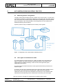


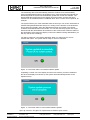

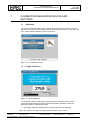
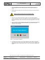

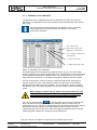
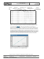
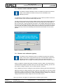


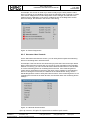
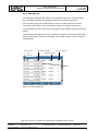


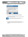


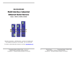

![*Sted Plus UG Jan 2012 [2].indd](http://vs1.manualzilla.com/store/data/005710511_1-f757ed41a0935df19f469c7cee361c5b-150x150.png)