1
HyCNC-4P(4 Axis)
USB Motion Control
Parallel Port Interface
Instruction Manual
HyTechWorks 2010 – V3.1
Cautions
HyTechWorks provides its products and services “as it is”.
HyTechworks accepts no responsibility for performance of
any machine or any damage or injury caused by using its
products and services.
All computer controlled machine tools are potentially dangerous if they are
incorrectly designedor operated. It is your responsibility to insure that you
understand the implications of your design and build and the compliance
requirements with any legislation and codesof practice applicable to your
country. If you have any doubt, please consult qualified experts rather than
take risks.
HyTechWorks reserves the right to change its designs without further
notice.
HyTechWorks 2010 – V3.1
Contents
Introduction ............................................................................................................1
Minimum System Requirements.........................................................................2
Shape and Connections ......................................................................................3
DB25 Connector............................................................................................3
X/Y/Z/A Stepping Pulses ..........................................................................4
X/Y/Z/A Direction Pulses ..........................................................................5
PWM Outputs ..........................................................................................5
Relay Control Outputs (Original and B Type) ...........................................6
RS485 Port (C Type) .................................................................................6
Control Inputs ..........................................................................................6
USB Connector .............................................................................................7
Working Status LED..........................................................................................7
USB Driver Install..................................................................................................8
Multiple Connection ......................................................................................17
Mach3 Configurations ........................................................................................20
HyCNC-4P PlugIns .....................................................................................20
Relay Output Config (Original/B Type) ....................................................23
X/Y/Z/A Axis Config ........................................................................................25
Spindle and PWM2 Config .............................................................................28
Homing/Soft Limits ........................................................................................32
Slave Axis .......................................................................................................37
Auto Tool Setting ...........................................................................................39
EStop Configuration .......................................................................................47
Mach3 Watchdog Configuration ....................................................................50
RS485 (C Type Only)...............................................................................................52
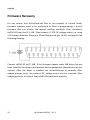
Firmware Update ...................................................................................................53
Normal Operation ..........................................................................................53
Firmware Recovery ........................................................................................58
Low Level API .........................................................................................................59
HyTechWorks 2010 – V3.1
Device Identification and Opening ................................................................59
Device Basic Information Reading .................................................................60
Motion Control ..............................................................................................61
Other Controls ...............................................................................................62
HyTechWorks 2010 – V3.1
Introduction
HyCNC-4P is a 4-axis machine tool motion control USB interface,
replacing traditional PC parallel port. Its operation features are as the
follows:
Connect to PC via USB port, suitable for any netbook, notebook,
desktop and tablet PC with USB ports.
USB kernel mode driver compatible with 32/64 bit Microsoft Windows
XP/Vista/7 OS.
Compatible with Mach3 PC based CNC software, including version
3.043.066.
Simultaneous connection for control axis expansion using API (127
USB device with 508 axis in theory), or control of multiple machines
with single PC running Virtual PC or VMWARE.
4 axis linkage operation with 250KHz(-250) / 125KHz(-125) /
60KHz(-60) / 30KHz(-30) maximum stepping pulse frequency for each
axis. The polarity of the direction signals can be defined according to
requirements.
A-axis cab be used as a slave axis.
2-stage fast homing on all axis and automatic alignment between the
master and slave axis during homing stage.
Support professional and low-cost automatic tool setters.
Emergency stop (can optionally stop PWM1/PWM2).
2 PWM outputs – PWM1 for spindle speed control and PWM2’s duty
cycle can be adjusted by a M code.
2 relay control outputs.
Small size and easy to use, similar to an usb-parallel port adapter.
Online firmware updating.
Firmware recovery mode to eliminate the danger of firmware updating.
Control signals on DB25 connector are defined as a PC parallel port
HyTechWorks©2013 – V3.1
1
with 5V signal level.
Working status LED.
Motion control using a 32bit single chip microcontroller, greatly
reducing real time requirement for PC OS.
All control pulses are generated using on-chip hardware, eliminating
motor vibration caused by control signal jitters.
Reliable design that can work under severe conditions.
Software watchdog monitors Mach3’s proper running.
Providing Windows API to support special control system (i.e. motion
control using LabView Windows).
RS485 Communication Port (HyCNC-4P-xxxC only).
Minimum System Requirements
Pentium 1GHz or similar CPU, i.e. Atom N270.
512MB memory.
32/64 bit Microsoft Windows XP, Windows Vista or Windows7 OS.
Mach3 software.
2
HyTechWorks©2013 – V3.1
Shape and Connections
HyCNC-4P is assembled in a plastic cover with a DB25 and two fasten
screws on one end, and an USB connector and working status LED on
another end.
Size:
74mm(L) x 58mm(W) x 24mm (D)
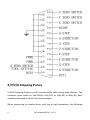
DB25 Connector
The DB25 connector has 17 control signals as the following figure.
HyTechWorks©2013 – V3.1
3
X/Y/Z/A Stepping Pulses
X/Y/Z/A Stepping Pulses are 0-5V position pulse with raising edge effective. The
minimum pulse width us 1uS(-250)or 2uS(-125) or 4uS(-60) or 8uS(-30). Each
output can be used to drive 15mA push and pull.
When connecting to a motor driver with low to high transaction, the following
4
HyTechWorks©2013 – V3.1
connection should be used:
When connecting to a motor driver with high to low transaction, the following
connection should be used (5V is not isolated from the HyCNC-4P):
X/Y/Z/A Direction Pulses
High level(5V) represents positive direction movement and low level (0V)
represents negative direction movement. Each output can be used to drive 15mA
push and pull.
The direction of a two-phase stepping motor can be changed by swapping
connection of one of the coils. Therefore, the connection to the motor driver can
be either one of the above connections.
If the motor direction can’t be changed by an external switch, the first connection
should be used for the motor moving position direction when the direction input
is driven and the second connection should be used for the motor moving
position direction when the direction input is not driven.
PWM Outputs
PWM1 and PWM2 have same base frequency (0.017-100000Hz adjustable by
software). PWM1’s duty cycle is proportional to spindle speed and PWM2’s duty
cycle can be adjusted by a M code. 0% duty cycle is low level and 100% duty cycle
is high level output. Each output can be used to drive 15mA push and pull,
HyTechWorks©2013 – V3.1
5
capable to drive an optical coupler like stepping pulse outputs do.
Relay Control Outputs (Original and B Type)
OUt1 and OUT2 can be used to control 2 relays with relay drivers. Each output
can be used to drive 15mA push and pull.
OUT1 is mapped to Mach3’s digital output port 1 pin 0.
OUT2 is mapped to Mach3’s digital output port 1 pin 1.
RS485 Port (C Type)
OUT1 – RS485+
OUT2 – RS485-
Control Inputs
There are X-axis zero, Y-axis zero, Z-axis zero, A-axis zero/tool setter and EStop 5
inputs. Each input is connected to a microcontroller (3.3V supply) pin via a 10K
resistor without using voltage converters. The signal switching level is not
compatible with 5V circuitry. It is low level when input voltage < 1.15V and high
level when input voltage > 2.15V.
X-axis zero is mapped to Mach3 digital input port 1 pin 5.
Y-axis zero is mapped to Mach3 digital input port 1 pin 4.
Z-axis zero is mapped to Mach3 digital input port 1 pin 3.
A-axis zero/tool setter is mapped to Mach3 digital input port 1 pin 7 (B Type is pin
9).
EStop 5 is mapped to Mach3 digital input port 1 pin 12.
6
HyTechWorks©2013 – V3.1
USB Connector
The USB connector is used to communicate with a PC. Please use a high
quality USB2.0 cable for better resistance of disturbance.
Working Status LED
Flash Rate
Status
1 flash/s
Normal working,whithout motion instruction.
2 flash/s
Normal working , with motion instructions (including zero
motions).
5 flash/s
Firmware update.
HyTechWorks©2013 – V3.1
7
USB Driver Install
Attention: USB driver install requires “administrator” privilege.
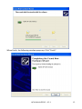
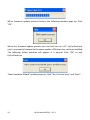
Double click install.bat under “USB Driver” directory. The install program will
choose proper driver depends on the OS.
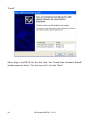
The following window pops up. Click “Next”.
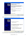
Then the “Important Notice” window appears. Please read the “Important Notice”
carefully. If agree, select “I accept” the click “Next”.
8
HyTechWorks©2013 – V3.1
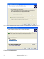
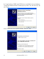
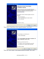
Windows Vista/7 will show the following warning. Click “Install this driver
software anyway”.
Then the driver install begins. The following window pops up when finish. Click
HyTechWorks©2013 – V3.1
9
“Finish”.
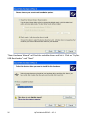
When plug in HyCNC-4P for the first time, the “Found New Hardware Wizard”
window pops up. Select “Yes, this time only” the click “Next”.
10
HyTechWorks©2013 – V3.1
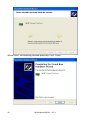
Select “Install from a list or specific location” then click “Next”.
Select “Don’t search. I will choose the driver to install” then click “Next”.
HyTechWorks©2013 – V3.1
11
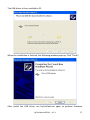
PC will show suitable drivers. Select “HyCNC-4P USB Interface” then click “Next”.
PC starts installing the driver.
12
HyTechWorks©2013 – V3.1
When finish, the following window poops up. Click “Finish”.
HyTechWorks©2013 – V3.1
13
For C type hardware, RS485 virtual COM driver is installed for the new hardware.
“Found New Hardware Wizard” window pops up. Select “Yes, this time only” the
click “Next”.
Select “Install from a list or specific location” then click “Next”.
14
HyTechWorks©2013 – V3.1
Select “Don’t search. I will choose the driver to install” then click “Next”.
PC will show suitable drivers. Select “HyCNC RS485l Com Port” then click “Next”.
PC starts installing the driver.
HyTechWorks©2013 – V3.1
15
When finish, the following window poops up. Click “Finish”.
16
HyTechWorks©2013 – V3.1
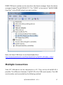
RS485 COM port number can be view from the device manager. Open the device
manager. Expand “Ports(COM & LPT)”. The “COM3” at the back of “HyCNC RS485
Com Port” is the RS-485 virtual com port number.
Note: the latest USB driver can be downloaded from
http://www.hytechworks.com/Downloads/HyCnc/HyCNC_4P/index_e.html
Multiple Connection
Total 127 USB device can be connected to a PC. They can be all HyCNC-4P if
possible. The difference between 2 HyCNC-4P is the USB serial number. The USB
serial number can be revealed by the following method.
HyTechWorks©2013 – V3.1
17
Plug a HyCNC-4P in to PC. The open Windows’ “Devcie Manager” shown below.
Expend “HyTechworks Hardware” to show all plugged in interface. Right click the
interface, select “Properties”.
Then click “Details” page and select “Device Instance Id”. The last 8 characters
following the VID and PID number is the USB serial number.
18
HyTechWorks©2013 – V3.1
HyTechWorks©2013 – V3.1
19
Mach3 Configurations
Please refer to proper materials regarding to Mach3 install.
Mach3 software download: http://www.machsupport.com/downloads.php
Mach3 document download: http://www.machsupport.com/documentation.php
There is no need to install Mach3 parallel port driver, which is not functional
under 64 bit Windows. Normal USB-parallel port adapter cables don’t work as
well. The motion pulses have jitters because Windows’ scheduling.
The following descriptions only address configuring HyCNC-4P for Mach3.
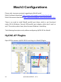
HyCNC-4P PlugIns
Open ZIP file contains HyCNC-4P.DLL and drag it to Mach3/PlugIns.
20
HyTechWorks©2013 – V3.1
Note: the latest Mach3 plugin can be downloaded from
http://www.hytechworks.com/Downloads/HyCnc/HyCNC_4P/index_e.html
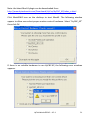
Click Mach3Mill icon on the desktop to start Mach3. The following window
appear to allow user select proper motion control hardware. Select “HyCNC_4P”
then click OK.
If there is no suitable hardware to run HyCNC-4P, the following error windows
appears.
HyTechWorks©2013 – V3.1
21
If there are more than on HyCNC-4P connected to the PC, another selection
window appears. All available HyCNC-4P are listed in the window by their USB
serial number. Select the one intend to use and click OK. If there is only one
HyCNC-4P, no more windows will be shown and the only one HyCNC-4P will be
used.
The firmware version and the hardware serial number of the HyCNC-P cab be
read by operate Mach3 main menu ”Config”->”Config PlugIns”.
Click “CONFIG” behind HyCNC_4P and a new windows shows up.
22
HyTechWorks©2013 – V3.1
FW is the firmware version and SN is the hardware serial number.
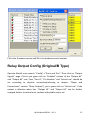
Relay Output Config (Original/B Type)
Operate Mach3 main menu’s “Config”->”Ports and Pins”. Then click on “Output
Signals” page. Click to put green tick on “Enabled” column of the “Output #1”
and “Output #2” row. Their “Port #”, “Pin Number” and “Active Low” should be
set according to physical connection(referring to chapter “Shape and
Connections”, section “Relay Outputs”), put a green tick on “Active Low” if the
output is effective when low. “Output #1” and “Output #2” can be further
mapped further to control mist, coolant and spindle motor etc.
HyTechWorks©2013 – V3.1
23
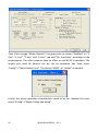
Coolant control can be used to test “Output #1” and “Output #2”. Click on page
“Spindle Setup”. Set as the following figure for “Relay Control” and “Coolant Mist
Control” blocks, in which “Output #1” is used to control mist and “Output #2” is
used to control coolant.
Then click Apply and OK to close the config window. Then switch to page
“Diagnostics” of the Mach3’s main interface and type “M7↙” to switch on mist,
24
HyTechWorks©2013 – V3.1
“M8↙” to switch on coolant, “M9↙” to switch both off. Check output change
accordingly.
X/Y/Z/A Axis Config
Operate Mach3 main menu’s “Config”->”Ports and Pins”. Click on page “Port
Setup an d Axis Selection”. Disable using “Port #1” and “Port #2” and keep
“Kernal Speed” at 25000Hz. This is only associated with PWM frequency setting
and has nothing to do with motion control using HyCNC-4P.
HyTechWorks©2013 – V3.1
25
Then click on page “Motor Outputs”. Put green ticks in column “Enabled” on “X
Axis”, “Y Axis”, “Z Axis” and “A Axis” row and “Dir LowActive” according to the
requirements. The other columns have no effect on HyCNC-4P’s operation. The
length unit used by Mach3 can be set by operation the main menu
“Config”->”Select Native Units”. The choose “MM’s” or “Inches” as needed.
Finally, the motor operation characteristics need to be set. Operate the main
menu “Config”->”Motor Tuning and Setup”.
26
HyTechWorks©2013 – V3.1
Click on “X Axis” button on the upper right corner. Then fill in “Ster per”
(mm/inch) according to the following equation
step motor steps per revolution · driver microstep setting
screw pitch
For example, the step has 200 steps per revolution. The driver microstep is 20.
The screw pitch us 4mm. Then 1000 should be filled in “Set per” box.
“Velocity” is the maximum distance X-axis is allowed to move per minute. It is the
maximum speed of G0 code. It also limits the maximum value for F code. The
machine mechanical and control system performance limit the “Velocity”, as well
as the “Acceleration” value after it.
The pulse width settings are not used by HyCNC-4P. Press “SAVE AXIS SETTINGS”
to save X-axis settings. Then do same for “Y Axis”, “Z Axis” and “A Axis”.
The jogging can be used to test axis settings. Press “TAB” key on the keyboard to
show jogging window as the following figure. First make sure Mach3 is not in
“RESET” state by checking “RESET” button on the lower left corner not flashing
HyTechWorks©2013 – V3.1
27
red-green box. If Mach3 is in reset state, click on “RESET” button to release the
reset state (a steady green box encapsulate “RESET”). Press “X+” and “X-“ in the
jogging window to check X movement. Press “Y+” and “Y-“ to check Y movement.
Press “Z+” and “Z-“ to check Z movement and press “A+” and “A-“ to check A
movement(if fitted).
The jog response speed can be adjusted by “Jog Buffer” length in “HyCNC-4P”
plugin’s “CONFIG” setting. The smaller the buffer is set, the faster response speed
becomes. However, the larger chance of inconstant motion caused by PC OS’s
scheduling timing error.
Spindle and PWM2 Config
Operate the main menu “Config”->”Ports and Pins”. Click on page “Motor
28
HyTechWorks©2013 – V3.1
Outputs”. Put a green tick on the “Spindle” row’s “Enabled” column. All other
columns are not used by HyCNC-4P.
Then click on page “Spindle Setup” page. If there is no circuit to control spindle
rotating direction. Put a “X” on “Disable Spindle Relay”. If spindle’s rotating
direction can be controlled by a H-bridge consisted by 2 relays, 2 relay outputs
are needed. If spindle’s rotating direction can be controlled by a H-bridge
consisted by 1 relays, 1 relay outputs are needed and the other is set to the
undefined output. The PWM1 and PWM2 base frequency is calculated by
equation
25000 x 10
“PWM base Freq”value
The PWM1 and PWM2’s duty cycle is controlled by the hardware. Its accuracy is
has nothing to do with “Kernel Speed”.
HyTechWorks©2013 – V3.1
29
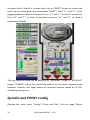
The ratio between PWM1’s duty cycle and spindle speed is set by operating the
main menu “Config”->”Pulley Selection”. “Min Speed” is for 0% duty cycle and
“Max Speed” is for 100% duty cycle. If “Min Speed” is for 100% duty cycle and
“Max Speed” is for 0% duty cycle, put “X” on “Reversed”.
The spindle operation can be tested by select the main menu “Function
Cfg’s”->”Spindle Calibration”. Put a test value in RPM box and click “Spindle
On/Off” button to start spindle. When spindle is rotating, the PWM1 duty cycle is
shown in “Control Ratio” box. Click click “Spindle On/Off” button to stop spindle
and the “Control Ratio” box shows 0.
30
HyTechWorks©2013 – V3.1
When PWM2 is not used for Mach3 watchdog status output, PWM2 ‘s duty cycle
can be set by using a M code, i.e.” M101”. Create a new text file called m101.m1s
under Mach3/Macros/Mach3Mill directory. Fill the following content by a text
editor and save.
Declare Sub PWM2_SetDutyCycle Lib "HyCNC_4P"(ByVal duty As Double)
PWM2_SetDutyCycle(Param1())
PWM2_SetDutyCycle is a function declared in HyCNC_4P.DLL. It takes a double
input value between 0.0 – 1.0 that controls the PWM2’s duty cycle. Such value is
provided by P parameter of M101 code (via Param1()). To test this M code, click
on page “MDI” of the Mach3’s main interface. Type “M101 P0.3↙” on the MDI
input box and check 30% duty cycle output on PWM2. This M code can be used in
GCode file(*.TAP) as well.
HyTechWorks©2013 – V3.1
31
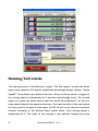
Homing/Soft Limits
The homing process is divided into 2 stages. The first stage is to seek the home
switch with speed of G0 speed’s predefined percentage (plugin config’s “Home
Speed%”) according to pre-defined direction. When the home switch is triggered,
the moving speed is decelerated to 0 and the second stage starts. The second
stage is to leave the home switch with the speed of predefined % of the first
stage speed towards the opposite direction. The home position is the spot where
the home switch changes its state again. HyCNC-4P will set its internal coordinate
counter according to the defined home switch offset. Then moving speed is
decelerated to 0. The order of the homing is also defined. Operate the main
32
HyTechWorks©2013 – V3.1
menu “Operator”-> “Edit Button Script”. The click on flashing “REF ALL HOME” to
bring up the homingscript edit window.
DoButton(22), DoButton(23), DoButton(24), DoButton(25), DoButton(26),
DoButton(27) are used to execute auto zero on X/Y/Z/A/B/C axis. The above
script execute homing on Z axis, then Y axis, then X axis and finally A axis.
DoOEMButton(133), DoOEMButton(134), DoOEMButton(134) are used to reset
X/Y/Z encoder. For the machine without encoder, these 3 line of script can be
removed. More code can be added to the script to suit a specific machine. For
example, a fast move to a predefined coordinate, i.e. (10, 15, 5, 90) is required
after homing. The script looks like this.
DoButton(24)
DoButton(23)
DoButton(22)
DoButton(25)
While IsMoving()
Sleep(100)
Wend
HyTechWorks©2013 – V3.1
33
code("G0 Z5")
While IsMoving()
Sleep(100)
Wend
code("G0 X10 Y15 A90")
This script execute homing like before. After homing is finished, it first fast moves
Z axis to coordinate 5. After Z axis movement is finished, it fast moves to 10 on X
axis, 15 on Y axis with 90 on A axis at the same time. After edit the script, save it
to the system by operating menu “File” -> “Save”. Clicking “REF ALL HOME” can
run the saved script. If homing needs to be run from a GCode file, save above
script to a mXXX.m1s file (i.e. m299.m1s) under Mach3/Macros/Mach3Mill
directory.
More settings are needed to get homing working properly.
Operating the main menu “Config”->”Ports and Pins” and click on page “Input
Signals”. Put green ticks in “X Home”, “Y Home”, “Z Home” and “A Home” row’s
“Enabled” column if homing is required on X/Y/Z/A axis. Their “Port #”, “Pin
Number” and “Active Low” should be set according to physical connections
(referring to chapter “Shape and Connections”, section “Control Inputs”). If the
inputs are low level effective, put green ticks in “Active Low” columns.
34
HyTechWorks©2013 – V3.1
Then operating the main menu “Config”->”Motor Home/SoftLimits”. For the axis
equipped with a home switch that requires the homing process, put a green tick
in their “Auto Zero” column (attention: A axis home switch input shares the same
input as the auto tool setting input(If homing is enabled on A axis, the auto tool
setting can’t be enabled). “Home Neg” column defines the location of the
homing switch. If the switch is on the negative direction (seeking towards
negative direction for the home switch in the first stage), put a green tick in this
column. “Speed %” defined the maximum speed of the second stage as the
percentage of the first stage. When this setting generates stepping pulses more
than 1000Hz, the accuracy is also affected. In this case, the homing accuracy in
theory is
distance per step · pulse frequency
1000
“Home Off.” is the machine coordinate of the zero switches. its value is set to
HyCNC-4P coordinate when the home switch is triggered again in the second
stage.
“Soft Max” and “Soft Min” define the working range of an axis. “Slow Zone”
define deceleration distance before each ends. These values should be set
HyTechWorks©2013 – V3.1
35
properly according to work range to avoid mechanical collision. For small CNC
machine tools using step motors, home switches with soft limits provide an
effective and low cost solution for safe machine operation.
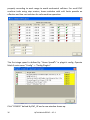
The first stage speed is defined by “Home Speed%” in plugin’s config. Operate
Mach3 main menu “Config” -> ”Config PlugIns”.
Click “CONFIG” behind HyCNC_4P and a new window shows up.
36
HyTechWorks©2013 – V3.1
Set and test “Home Speed%”. It is percentage of the speed limits.
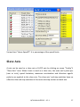
Slave Axis
A-axis can be used as a slave axis of X/Y/Z axis by clicking on menu “Config”’s
“Slave Axis” item. When A-axis is used as a slave axis, the main axis’s pulse per
(mm or inch), speed limitation, maximum acceleration and direction signal’s
polarity are applied to the slave axis. The slave axis’ end-stop switches have no
effect but the end stop switches of the main axis stop motion on both axis.
HyTechWorks©2013 – V3.1
37
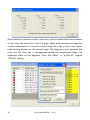
When homing is carried out with a slave axis, machine seeks both home switches
on the main and slave axis in the first stage. When both switches are triggered,
machine decelerates to 0 and the second stage start. The machine also checks
both homing switches in the second stage. The alignment error between the
main and the slave axis is compensated during the deceleration stage. The
alignment offset can be adjusted “Slave Axis Offset” in “HyCNC-4P” plugin’s
“CONFIG” setting.
38
HyTechWorks©2013 – V3.1
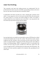
Auto Tool Setting
Two commonly used auto tool setting processes are implemented. One for
professional tool setter (one with retreatable spring loading surface) and one for
low cost tool setter (one with hard non-retreatable surface).
A professional tool setter normally has 2 wires, working like a precision micro
switch. It uses magnets to stick on the bench top stably. When the tool presses
the surface down to a fix point, the switch changes its status. The switch is
usually isolated from the mechanical parts electrically. It can connected to the
tool setter input pin without using an optical coupler.
Low cost tool setter can simply be constructed by a piece of PCB board or a block
of metal with isolation layer on one of its surface. This kind of tool setter requires
conductive tool bits, forming a close circuit when tool bits touch the tool setter
surface. An optical coupler is required to interface with tool setter input safely, as
shown in the following figure. GND2 is the ground of +24V. It is connected to the
machine and tool using the black crocodile clip. 1800 ohm resistor limit the
current through the LED to 10-20mA when the tool touches the PCB surface. The
closing circuit status optically coupled to the transistor side, grounding the tool
setter input.
HyTechWorks©2013 – V3.1
39
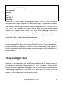
There is an improved low cost tool setter shown in the figure below. It requires
the same connection and optical coupler circuit as the low cost tool setter
described above. However, its setting method should be as same as the
professional one.
Two tool setting methods are selected by operating Mach3 main menu “Config”
-> ”Config PlugIns”.
40
HyTechWorks©2013 – V3.1
Click “CONFIG” behind HyCNC_4P and a new window shows up.
Putting “X” before “ATS Stop on Touch” selects auto tool setting using low cost
tool setter. Removing “X” before “ATS Stop on Touch” selects auto tool setting
using professional tool setter.
HyTechWorks©2013 – V3.1
41
Process of using professional tool setter is similar to auto zero. The first stage is to
seek tool setter with acceleration to G0 speed according to pre-defined direction.
When tool setter is triggered, the moving speed is decelerated to 0 and the
second stage starts. The second stage is to leaving the tool setter with
acceleration to predefined % of the G0 speed towards the opposite direction.
When tool setter changes its status, the difference between Z-axis coordinate and
predefined tool setter surface coordinate is used as the tool length offset and
save in tool library database. The movement decelerates to 0 then accelerates to
G0 speed to the coordinate where tool setting started. This process have
overshot when tool touches tool setter surface at first stage. Therefore, tool
setter with retreatable surface is required to avoid tool and/or machine damage.
A low cost tool setter has hard non-retreatable surface isolated from the machine
electrically. It doesn’t allowed overshot (or allows every small overshot), It
requires movement to stop immediately when the tool touch tool setter surface.
Setting process is to seek tool setter with acceleration to % of G0 speed according
to pre-defined direction. When tool touch the tool setter, movement stops within
1/1000s. The difference between Z-axis coordinate and predefined tool setter
surface coordinate is used as the tool length offset and save in tool library
database. Then machine accelerates to G0 speed to move the coordinate to
where tool setting started. Please pay attention, even with control system stops
within 1/1000s, the mechanical system may not stop fast enough to avoid tool
and/or machine damage. The % of G0 speed should be set small enough to avoid
such damage.
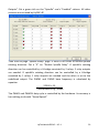
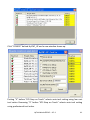
The tool setter input shares same input as the A-axis zero switch input. When
auto tool setting is used, A-axis auto zero can’t be used. Operate the main menu
“Config”->”Ports and Pins”. Click on page “Input Signals” shown below. The tool
setting is enabled by putting a green tick in the “OEM Trig #1” row’s “Enable”
column. “Port #”, “Pin Number” and “Active Low” should be set according to
physical connections (referring to chapter “Shape and Connections”, section
42
HyTechWorks©2013 – V3.1
“Control Inputs”). If the input is low level effective, put a green tick in “Active Low”
column. Then click “Apply” and “OK” to save the settings.
The operate the main menu “Config”->”Motor Home/SoftLimits”. The A-axis
settings are used for tool setting operation. If the tool setter is located on the
negative direction on Z-axis (moving negatively to seek tool setter), put a green
tick in column “Home Neg”. “Speed %” defines the % of G0 speed on Z-axis slow
movement. When this setting generates stepping pulses more than 1000Hz, the
accuracy is also affected. In this case, the homing accuracy in theory is
distance per step · pulse frequency
1000
HyTechWorks©2013 – V3.1
43
The tool setter surface Z-axis coordinate is defined using “Gauge Block Height”
box in main interface’s “Offset” page. Click on the box and type in the height and
return, as shown below.
44
HyTechWorks©2013 – V3.1
Finally, script for auto tool setting needs to be updated. Operate the main menu
“Operator”->”Edit Button Script”. Then click on flashing “Auto Tool Zero” button,
as shown below.
Type the following script in the new window.
Declare Sub AutoToolSetting Lib "HyCNC_4P"(ByVal ctool As Integer)
AutoToolSetting(GetOEMDRO(824))
AutoToolSetting is a function define in HyCNC_4P.DLL. The input parameter is the
tool number (the green circle in above figure), provided by GetOEMDRO(824)
standard function. Then click menu “file”->”Save”. When auto tool setting is
required, click on the tool number box (the green circle in above figure). Type in
tool number other 0 followed by return (tool 0 always has 0 offset). Then put tool
setter on the machine bench and jog the tool above center of the tool setter.
Press “Auto Tool Zero” to start tool setting process. After tool setting is finished,
the box indicated by the blue arrow (see above figure) is updated with the
measured tool length. Please pay attention, the new tool length won’t be used
immediately. To use the new value, either type G43 in MDI or click on page
“Offset” of the main interface. There is a button called “Turn Offset on/Off” and a
green indicator beside it. If the indicator is on, click “Turn Offset on/Off” twice to
use the new tool length offset. If the indicator is off, click “Turn Offset on/Off”
once to use the new tool length offset.
HyTechWorks©2013 – V3.1
45
The tool setting script can further adapted to the machine. For example, if the
tool setter is fixed at a location, i.e. machine coordinate (100, 50) and new tool
length is always used after tool setting, the script can be update as the following.
Declare Sub AutoToolSetting Lib "HyCNC_4P"(ByVal ctool As Integer)
code("G53 G0 X100 Y50")
While IsMoving()
Sleep(100)
Wend
AutoToolSetting(GetOEMDRO(824))
While IsMoving()
Sleep(100)
Wend
code("G43 ")
“G53 G0 X100 Y50” moves quickly to the center of the tool setter. When
movement is done, auto tool setting is executed. When setting process is finished,
G43 force the new tool length to be used.
If a manual tool change followed by auto tool setting is required from the GCode
file, save the following script to a mxxx.m1s file, i.e. m900.m1s, in
Mach3/Macros/Mach3Mill directory.
Declare Sub AutoToolSetting Lib "HyCNC_4P"(ByVal ctool As Integer)
code("G53 G0 Z200" )
While IsMoving()
Sleep(100)
Wend
DoSpinStop()
code("G53 G0 X500 Y500" )
MsgBox ("Press OK after tool change.", 0)
code("G53 G0 X100 Y50")
While IsMoving()
Sleep(100)
46
HyTechWorks©2013 – V3.1
Wend
AutoToolSetting(GetOEMDRO(824))
While IsMoving()
Sleep(100)
Wend
code("G43 ")
DoSpinCW();
Call M900 in GCode execute following operations: “G53 G0 Z200” moves the
current to a safe height suitable for manual tool change. Then spindle is stopped.
Then move to tool change located at machine coordinate (500, 500) by “G53 G0
X500 Y500”. The a window with confirm button pops up on the screen, waiting
manual tool change to be carried out. After tool changing, click on the
confirmation button to continue the program. The machine moves to the tool
setter center to start tool setting process. After the setting is finished, the new
tool length offset is used and spindle rotates again.
Attention: the safety of the manual tool changing operator is depend on the
proper running of the above script by the PC control system. If a safer condition is
required (even the malfunction of the PC control system doesn’t start spindle to
hurt the operator), install safety switches or consult experts or HyTechWorks for a
proper solution.
EStop Configuration
Attention: it is suggested to use the EStop provided by the PC control system as
the secondary or backup solution and use direct hardware solution as the
primary solution to guarantee stopping of the machine under critical conditions.
The following configuration of the EStop is all based on using PC and HyCNC-4P
interface. It is provided as it is for a reference only.
HyTechWorks©2013 – V3.1
47
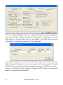
The EStop is enabled by operating the main menu “Config”->”Ports and Pins”,
clicking on page ”Input Signals” and putting a green tick on EStop’s “Enabled”
column. “Port #”, “Pin Number” and “Active Low” should be set according to
physical connections (referring to chapter “Shape and Connections”, section
“Control Inputs”). If the input is low level effective, put a green tick in “Active Low”
column. Then click “Apply” and “OK” to save the settings.
When EStop is trigged, the GCode execution is stopped. If 2 PWM outputs also
required to stop, put “X” on “PWM1=0 on EStop” and “PWM2=0 on EStop” in
“HyCNC-4P Config” window. The “HyCNC-4P Config” window can be shown by
operating the main menu “Config”->”Config PlugIns”.
48
HyTechWorks©2013 – V3.1
Then click on “CONFIG” box behind the “HyCNC-4P” .
HyTechWorks©2013 – V3.1
49
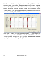
When external EStop is triggered, the Mach3 will be locked to stop state even
external EStop is released. The red “RESET” button continues having a green-red
box flashing. Click on the “RESET” button to release Mach3’s internal stop state. If
the external EStop is still engaged when the “RESET” button is clicked, the
internal stop can’t be released.
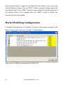
Mach3 Watchdog Configuration
A software watchdog can be enabled to monitor the proper working of the
Mach3. Operate the main menu “Config”->”Config PlugIns”.
Then click on “CONFIG” box behind the “HyCNC-4P” .
50
HyTechWorks©2013 – V3.1
Tick “Watchdog on PWM2” to enable the watchdog function. When Mach3 works
properly, PWM2 output a 50% duty cycle signal. When Mach3 works abnormally,
PWM2 output a 0 duty cycle signal. When watchdog is enabled, PWM2 can’t be
controlled by a M code. As soon as watchdog is enabled, it can’t be disabled until
USB interface’s power is recycled. To disable the watchdog, untick “Watchdog on
PWM2”, exit Mach3, recycle the USB interface’s power and restart Mach3.
HyTechWorks©2013 – V3.1
51
RS485 (C Type Only)
HyCNC-4P-xxxC has a RS-485 port to communicate with external modules, ie. VFC
controller. It is emulated as a serial port on PC windows. The port has the
following functions:
1. Automatic TX/RX modes changeover. TX mode has priority. Any sending data
put RS-485 in TX mode until data is transmitted and RX mode is recovered.
2. Gavanlic isolation.
3. Virtual COM port emulation.
4. Baud rate 300-115200bps.
5. 1/2 stop bits, odd/even/none polarity bit supported.
52
HyTechWorks©2013 – V3.1
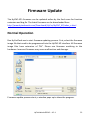
Firmware Update
The HyCNC-4P’s firmware can be updated online by the final users for function
extension and bug fix. The latest firmware can be downloaded from
http://www.hytechworks.com/Downloads/HyCnc/HyCNC_4P/index_e.html
Normal Operation
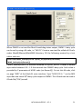
Run HyCncFlash.exe to start firmware updating process. First, select the firmware
image file that need to be programmed into the HyCNC-4P interface. All firmware
image files have extension of “fbl”. Please use firmware matching to the
hardware. Incorrect firmware may cause malfunction and damage.
Firmware update process starts, a window pops up to show the progress.
HyTechWorks©2013 – V3.1
53
When firmware update process finishes, the following window pops up. Click
“OK”.
When the firmware update process runs the first time on a PC, HyCncFlash.exe
can’t run properly because the firmware update USB driver has not been installed.
The following failure windows will appear. It is normal. Click “OK” to end
HyCncFlash.exe.
“New Hardware Wizard” window pops up. Click “Yes, this time only” and “Next”.
54
HyTechWorks©2013 – V3.1
Then click on “Install from a list or specific location” and “Next”.
Then click “Don’t search. I will choose the driver to install” and “Next”.
HyTechWorks©2013 – V3.1
55
“New Hardware Wizard” will find the suitable driver and list it. Click on “HyCnc
USB Bootloader” and “Next”.
56
HyTechWorks©2013 – V3.1
The USB driver is then installed to PC.
When the installation is finished, the following window pops up. Click “Finish”.
After install the USB driver, run HyCncFlash.exe again to perform firmware
HyTechWorks©2013 – V3.1
57
update.
Firmware Recovery
For any reason that HyCncFlash.exe fails to run properly in normal mode,
firmware recovery need to be performed to force re-programming a correct
firmware that can recover the normal working condition. First, disconnect
HyCNC-4P from the PC’s USB. Then connect a 7-10V DC voltage source (i.e. using
a 9V battery) between EStop (pin 10) and the ground (pin 18-25), as shown in the
following drawing.
Connect HyCNC-4P to PC USB. If the firmware update mode USB driver has not
been installed, the driver install process starts automatically (described in the last
section). After the driver is installed, run HyCncFlash.exe to normally. After
update process starts, the external DC voltage source can be removed. After
updating process is finished, the HyCNC-4P should work properly.
58
HyTechWorks©2013 – V3.1
Low Level API
Windows programs can use HyCNC-4P to generate motion and other control
signals via API functions. API consists of HyCNC_4P.LIB and its header file
HyCNC_4P.H. The latest API can be downloaded from
http://www.hytechworks.com/Downloads/HyCnc/HyCNC_4P/index_c.html
The API has following functions.
Device Identification and Opening
BOOL HyCNC_GetDevicePathByGUID(LPGUID DeviceGuid, char *DevicePath, DWORD
DeviceIndex)
HyCncLib_GetDevicePathByGUID identifys the path of a HyCNC-4P interface by its
driver GUID.
DeviceGuid – pointer to the device GUID.
DevicePath – pointer to store the device path string found according to the GUID
and device index.
DeviceIndex – index to the number of the device in system list, starting with 0.
If the function succeeds, the return value is true. Otherwise, it returns false.
HANDLE HyCNC_OpenDeviceByPath(char *DevicePath)
HyCncLib_OpenDeviceByPath opens HyCNC-4P interface by its path obtained
from calling HyCncLib_GetDevicePathByGUID.
DevicePath – pointer to the device path string.
If the function returns the device handle. If it fails, the handle is
INVALID_HANDLE_VALUE.
HyTechWorks©2013 – V3.1
59
Device Basic Information Reading
BOOL HyCNC_GetStatus(HANDLE hUsb, LPOVERLAPPED olp, HyCNC_StatusStruct *status)
HyCNC_GetStatus reads essential status from HyCNC-4P interface.
hUsb – the handle of the HyCNC interface.
olp – pointer to OVERLAPPED structure (see FileRead Visual C++ function for
overlapped I/O access)
status – status data read from HyCNC interface.
If the function succeeds, the return value is true. Otherwise, it returns false.
The status data have the following fields:
num – number of way point to fill the FIFO buffer in the HyCNC inteface.
cx – 32 bit x-axis coordinate count value in motor step.
cy – 32 bit y-axis coordinate count value in motor step.
cz – 32 bit z-axis coordinate count value in motor step.
ca – 32 bit a-axis coordinate count value in motor step.
cb – 32 bit b-axis coordinate count value in motor step.
cc – 32 bit c-axis coordinate count value in motor step.
din – port #1 inputs.
BOOL HyCNC_GetHardwareInfo(HANDLE hUsb, HyCNC_HardwareInfoStruct *info);
HyCNC_GetHardwareInfo reads HyCNC-4P hardware information.
hUsb - the handle of the HyCNC interface.
info - hardware infomation data.
If the function succeeds, the return value is true. Otherwise, it returns false.
hardware infomation data have the following fields:
type – hardware type.
axis – number of axis.
option – hardware option.
features – functional features
60
HyTechWorks©2013 – V3.1
fwv – firmware version
sn1 – serial number 1
sn2 – serial number 1
sn3 – serial number 1
Motion Control
BOOL HyCNC_SetMovement(HANDLE hUsb, LPOVERLAPPED olp, double *points, unsigned
char axis, unsigned short num)
HyCNC-4P generates interpolated stepping pulses with 1ms time base.
HyCNC_SetMovement sends the motor 1ms based movement vector data to
HyCNC-4P through USB.
hUsb – the handle of the HyCNC interface.
olp – pointer to OVERLAPPED structure (see FileWrite Visual C++ function for
overlapped I/O access)
points – pointer to the vector data. The vector data is organized in
(x0,[[[y0],z0],a0]), (x1,[[[y1],z1],a1]), (x2,[[[y2],z2],a2])…order.
axis – number of axis in vector.
num – number of vectors in data (no more than num return by
HyCNC_GetStatus).
If the function succeeds, the return value is true. Otherwise, it returns false.
BOOL HyCNC_PurgeMovement(HANDLE hUsb)
HyCNC_PurgeMovement clears all pending movement data in HyCNC-4P so that
stepping pulse can be stopped immediately.
hUsb – the handle of the HyCNC interface.
If the function succeeds, the return value is true. Otherwise, it returns false.
BOOL HyCNC_SetCoordinate(HANDLE hUsb, int* coordinate, int* mode)
HyCNC_SetCoordinate manipulates coordinate counters in HyCNC-4P.
HyTechWorks©2013 – V3.1
61
hUsb – the handle of the HyCNC interface.
coordinate – pointer to 4 element coordinate array that used to modify the
coordinate counters.
mode – pointer to 4 element mode array that defines the mode for coordinate
counter modifications. 0 – relative mode – the coordinate value is added to
current coordinate counter. 1 – absolute mode - the coordinate value is set to
current coordinate counter.
If the function succeeds, the return value is true. Otherwise, it returns false.
Other Controls
BOOL HyCNC_SetSwitch(HANDLE hUsb, unsigned int val)
HyCNC_SetSwitch sets relay output on/off.
hUsb – the handle of the HyCNC interface.
val – output level. Bit 0 –OUT1. Bit 1 – OUT2.
If the function succeeds, the return value is true. Otherwise, it returns false.
BOOL HyCNC_SetSpindle0(HANDLE hUsb, unsigned short period, unsigned short
prescale)
HyCNC_SetSpindle0 sets base frequency for PWM1 and PWM2.
hUsb – the handle of the HyCNC interface.
72000000
Freq =
𝐹𝐹𝐹𝐹
period · prescale
BOOL HyCNC_SetSpindle1(HANDLE hUsb, unsigned short duty)
HyCNC_SetSpindle1 sets PWM1’s duty cycle.
hUsb – the handle of the HyCNC interface.
Duty Cycle =
duty
period
BOOL HyCNC_SetSpindle2(HANDLE hUsb, unsigned short duty)
62
HyTechWorks©2013 – V3.1
HyCNC_SetSpindle2 sets PWM2’s duty cycle.
hUsb – the handle of the HyCNC interface.
Duty Cycle =
BOOL HyCNC_KickWatchdog(HANDLE hUsb)
duty
period
This function send a normal working signal to USB interface. The first signals
enable the watchdog if it is not enabled. This function needs to be called every
0.1 second. If it is not called in 0.5 second, the watchdog times out.
hUsb – the handle of the HyCNC interface.
BOOL HyCNC_CaptureCoordinate(HANDLE hUsb, int* data, int size, unsigned int
trigger, unsigned short hw_type)
This function captures the coordinate readings when home switches’ inputs or
tool setting input is toggled.
hUsb – the handle of the HyCNC interface.
data – pointer that hold the current coordinate readings. The order of the data is
as the follow:
Data[0] – X-coordinate reading when X homing switch input toggled if X
capture trigger is set.
Data[1] – Y-coordinate reading when Y homing switch input toggled if Y
capture trigger is set.
Data[2] – Z-coordinate reading when Z homing switch input toggled if Z
capture trigger is set.
Data[3] – A-coordinate reading when A homing switch input toggled if A
capture trigger is set.
Data[4..7] – X/Y/Z/A-coordinate readings when tool setting switch input
toggled if tool setting capture trigger is set.
size – number of data to read.
trigger – capture trigger setting. The trigger is reset when the input toggles.
bit 0 – X capture trigger. “1” sets and “0” has no effect.
bit 1 – Y capture trigger. “1” sets and “0” has no effect.
HyTechWorks©2013 – V3.1
63
bit 2 – Z capture trigger. “1” sets and “0” has no effect.
bit 3 – A capture trigger. “1” sets and “0” has no effect.
bit 31 – tool setting capture trigger. “1” sets and “0” has no effect.
hw_type – hardware type (see HyCNC_GetHardwareInfo). 1 – original type; 2 – B/C
type.
The switch input is evaluated every millisecond. The movement should be no
more than 1 pulse per millisecond to achieve the best result when the trigger for
that moving axis is set.
This function is useful for homing or tool setting. The trigger is set during the
homing or tool setting stage, when the switch input changed, the coordinate is
captured. Then the coordinates are read back without any trigger setting. The
captured coordinate can be subtracted from the current coordinate to achieve
“zero” effect.
64
HyTechWorks©2013 – V3.1