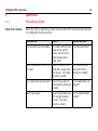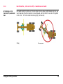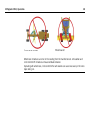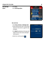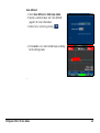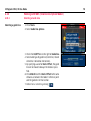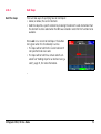
1
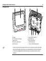
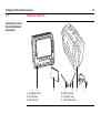
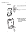
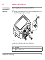
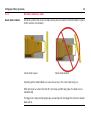
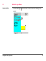
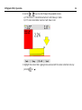
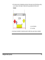
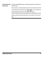
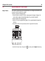
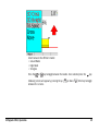
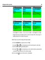
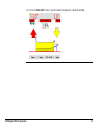
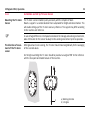
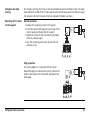
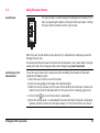
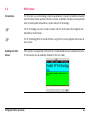
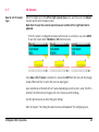
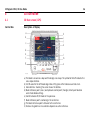
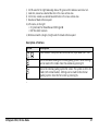
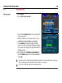
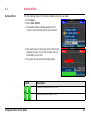
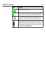
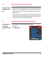
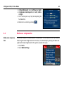
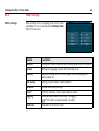
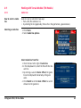
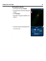
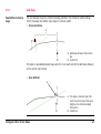
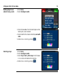
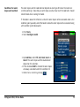
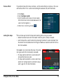
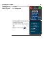
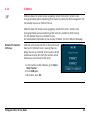
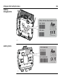
Leica iCONgrade iCP42 User Manual Version 1.0 English iCONgrade iCP42, Introduction 2 Introduction Purchase Congratulations on your purchase of the iCP42. The iCP42 is an ideal tool for increasing productivity in all aspects of the construction earthmoving industry. This manual contains important safety directions as well as instructions for setting up the system and operating it. Refer to "6 Safety Directions" for further information. Read carefully through the User Manual before you switch on the product. To ensure safety when using the system, please also observe the directions and instructions contained in the User Manual and Safety Handbook issued by the: • Machine manufacturer and • System manufacturer. Product identification The type and serial number of your products are indicated on the label on the base of the unit. Enter the model and serial number in your manual and always refer to this information when you need to contact your agency or Leica Geosystems authorised service workshop. Type: iCP42 Serial No.: _________________________ Symbols The symbols used in this manual have the following meanings: Type Description Danger Indicates an imminently hazardous situation which, if not avoided, will result in death or serious injury. Warning Indicates a potentially hazardous situation or an unintended use which, if not avoided, could result in death or serious injury. Caution Indicates a potentially hazardous situation or an unintended use which, if not avoided, may result in minor or moderate injury and/or appreciable material, financial and environmental damage. Important paragraphs which must be adhered to in practice as they enable the product to be used in a technically correct and efficient manner. Trademarks • GSM is a trademark owned by the GSM Association. All other trademarks are the property of their respective owners. Validity of this manual This manual applies to the iCONgrade iCP42. To use the iCP42 efficiently it’s inalienable to refer to the manual provided together with the software running on the iCP42. iCONgrade iCP42, Introduction 3 iCONgrade iCP42, Table of Contents 4 Table of Contents In this manual Topic 1 Page Product Overview 1.1 1.2 2 3 Product Description and Features Container Contents 7 7 10 Commissioning 11 2.1 2.2 2.3 2.4 11 13 14 14 Installation Installation a SIM Card/USB-Stick Inspection Prior to Commissioning Commissioning Operation 16 3.1 16 17 18 19 21 22 23 26 28 32 34 37 39 41 3.2 3.3 3.4 3.5 3.6 Pre-power up checks 3.1.1 Best operation practice for Grader Systems 3.1.2 Mast orientation 3.1.3 No Articulation, circle center shift, or wheel lean on Grader 3.1.4 Grader blade cushioning off 3.1.5 No blade rotation on Dozer Select the Input Source Setting a Reference Height Using the MUS1300 Tri-Sonic Sensor 3.4.1 Installation and Set Up Tri-Sonic Sensor 3.4.2 Operation with the Tri-Sonic Sensor 3.4.3 Swap Function Using the Laser Sensor SP14 Sensor 3.7 3.8 3.9 4 43 45 48 3D Run Mode 56 4.1 4.2 4.3 4.4 4.5 4.6 4.7 4.8 4.9 56 58 59 61 61 62 63 64 65 65 67 70 70 71 74 80 81 82 84 89 4.10 4.11 4.12 4.13 4.14 4.15 4.16 5 3D Sensors Setting the Value for Gain and Deadband Sensor Calibration Wizard 3D Run screen (GPS) Storing Points Vertical Offset Blade reference point and hydraulic control point Selecting Blade reference point and Hydraulic control point Blade wear compensation Screen Settings Other Settings Working with Terrain Models (TIN Models) 4.9.1 Guide Line 4.9.2 Hold Slope Working with MBS (Volume Description Model) 4.10.1 Selecting a Guide Line 4.10.2 Hold Slope Working with String Line Models (.lmd) Monitor Screen Transferring Files via USB Selecting Projects and Reference Models Localisation Settings (Coordinate Systems) iCONnect Care and Transport 91 5.1 5.2 5.3 91 91 92 iCONgrade iCP42, Table of Contents General Notices Transport Storage 5 iCONgrade iCP42, Table of Contents 5.4 6 8 Cleaning and Drying Safety Directions 6.1 6.2 6.3 6.4 6.5 6.6 6.7 7 6 General Intended Use Limits of Use Responsibilities Hazards of Use Electromagnetic Compatibility EMC FCC Statement, Applicable in U.S. 92 93 93 93 94 95 96 100 103 Technical Data 105 7.1 7.2 105 107 iCONgrade iCP42 Technical Data Conformity to National Regulations International Limited Warranty, Software License Agreement 110 1 Product Overview 1.1 Product Description and Features General The iCP42 has a key pad and touch screen for user input. The display is a 7" wide screen and has state of the art brightness, making it possible to use in sunny environments. The rugged IP56 enclosure is designed for harsh environments. Power Supply and Communication For utmost reliability in harsh and dusty environment, no connecting cables or power supply plugs are used at the iCP42. • • • • "Cradle" will be used as a short form for MMB1300 cradle throughout this manual. The iCP42 is wirelessly powered over the cradle via induction. Data are transferred wirelessly via IR between the MMB1300 cradle and the iCP42. The iCP42 has WLAN hardware support (for future use). On the bottom of the iCP42 are connectors for SIM card and USB. iCONgrade iCP42, Product Overview 7 iCONgrade iCP42, Product Overview iCONgrade iCP42 a 8 b iCP42_001 a c f d g h i e j f a) b) c) d) e) Keypad 7" LCD wide screen display WiFi antenna IR-Port for data transfer HSPA antenna • • • Do not cover the IR-Port for data transfer as this can lead to a transfer interruption. Both, the HSPA and the WiFi antenna are not attached to the iCP42 when delivered. To store the iCONgrade iCP42 inside the transport case both antennas must be detached. f) g) h) i) j) Reverse SMA Connectors Ventilation cap SIM card connector USB 2.0 connector Cover for communication ports Warning Warning This product may be installed on building machinery only by an appropriately trained and qualified specialist. Unauthorised modification of machines by mounting the product may alter the function and safety of the machine. Precautions: Follow the instructions of the machine manufacturer. If no appropriate instruction is available, ask machine manufacturer for instructions before mounting the product. iCONgrade iCP42, Product Overview 9 iCONgrade iCP42, Product Overview 1.2 10 Container Contents Container for instrument and delivered accessories iCP42_002 a a) iCONgrade iCP42 b) User Manual c) WiFi antenna b c d d) HSPA antenna e) Transport case f) USB memory stick e f 2 Commissioning 2.1 Installation Installation information The iCP42 is ready to use when delivered from factory, no installation procedure is needed. To get the iCP42 started complete the following steps: 1. Snap iCP42 onto cradle. To connect the iCP42 to the cradle: 1. Put the iCP42 on the holding hooks in the bottom of the cradle. 2. Then snap the iCP42 onto the cradle by pressing it towards the cradle. 2 1 1 iCP42_003 iCONgrade iCP42, Commissioning 11 iCONgrade iCP42, Commissioning 12 2. Turn iCP42 on. To turn the iCP42 on and off, use the power switch on the right side of the cradle. This is the master switch for the entire system. Removing the iCP42 will also turn off the power. iCP42_004 2 1 iCP42_005 To release the iCP42 simply press the release key at the bottom of the cradle and pull the iCP42 towards you and then lift it up. 2.2 Installation a SIM Card/USB-Stick Insert and remove a SIM card/USB-Stick step-by-step Follow the step-by-step instructions to install a SIM card/USB-Stick. To remove the SIM card/USB-Stick place the instrument on a stable surface first. Then follow the following instructions in reverse order. 3 4 2 1 iCP42_007 Step 1. iCONgrade iCP42, Commissioning 5 Place the instrument onto a stable surface. (Not illustrated) Description Rotate the ring to the left. 13 iCONgrade iCP42, Commissioning Step 2.3 Inspection 14 Description 2. Pull the ring to open the protection cap. 3. Orientate the SIM card as illustrated. 4. Insert the SIM card into the card slot and push it in until it locks in place. 5. Insert the USB-Stick into the USB slot and push it in until it locks in place. Inspection Prior to Commissioning 1. Check that the cradle on/off switch is put into off position. 2. Check that the iCP42 is readily snapped into the cradle. 3. Check that the cradle LEDs are operating normally. • The top led should blink to show that messages are being transmitted from the CAN bus over the IR link. • The middle LED should blink to show that messages are being received from the CAN bus over the IR link. • The bottom LED should remain on to show that the cradle has sufficient power. 2.4 Commissioning Power supply The iCP42 is powered in the following way: • Induction based power through the backside of the iCP42 facing the cradle. iCONgrade iCP42, Commissioning 15 iCONgrade iCP42, Operation 16 3 Operation 3.1 Pre-power up checks State of the machine Before the system is powered up, please check the state of the machine to make sure that it is configured to function correctly. Check and set When? To learn how, see … Mast perpendicular to wheelbase. For Graders without mast "3.1.2 Mast orientation" slope sensor, and for Dozers, every time the blade changes attack angle (pitch). No articulation and circle side shift Every time a job is to be "3.1.3 No Articulation, on Grader. made with a single eleva- circle center shift, or tion sensor + cross slope wheel lean on Grader" sensor on a Grader. Turn Grader blade cushioning off. Every time you want to "3.1.4 Grader blade cushuse automatic controls on ioning off" a Grader. Dozer blade square. Every time you begin a job "3.1.5 No blade rotation with a single elevation on Dozer" sensor + cross slope sensor on a Dozer 3.1.1 Best operation practice for Grader Systems Tips for best performance Below you will find a list of things that will help achieve the best results when operating a Grader system. • • • • • • • iCONgrade iCP42, Operation Ensure that mast is perpendicular to the wheelbase, or use a mast slope sensor. Keep the circle centered under the gooseneck. Do not lean the wheels. Do not articulate the machine. Where possible, move the machine in one direction only; do not turn around. Where possible, set the blade rotation and leave it in the same position. Where possible, run with the slope sensor trailing, not leading. 17 iCONgrade iCP42, Operation 18 3.1.2 Mast orientation Mast orientation For Dozers and Graders without mast slope sensor, you must make sure that the mast is at the “as measured” position (that is, the position the mast or masts were in during the mast measure up). On a Dozer this means that the mast should not be mechanically sloped. If for some reason the mast is actually mechanically sloped, a new mast measure up must be done. On a Grader the blade should be tipped back towards its end stop, if that was the original measure position. 3.1.3 No Articulation, circle center shift, or wheel lean on Grader Articulation, circle Centershift, and wheel lean For Grader systems that rely on the cross slope sensor, and a single elevation sensor, you must make sure that the machine is not articulated and that there is no side shift applied to the circle. The front wheels must be upright (not leaned). Okay iCONgrade iCP42, Operation Articulated 19 iCONgrade iCP42, Operation Circle center shifted 20 Wheel leaned Wheel lean introduces an error in the reading from the mainfall sensor. Articulation and circle Centershift introduce unmeasured blade rotation. Operating with wheel lean, circle centershift or articulation can cause inaccuracy in the cross slope being cut. 3.1.4 Grader blade cushioning off Blade cushioning off Using a Grader’s blade cushioning device at the same time as the blade is being automatically controlled by the system results in poor automatic control performance. Make sure that blade cushioning, if installed, is turned off before working with automatic controls. iCONgrade iCP42, Operation 21 iCONgrade iCP42, Operation 22 3.1.5 No blade rotation on Dozer Dozer blade rotation For Dozer systems that use a cross slope sensor you must make sure that the blade is square to the machine (not rotated). Dozer blade square Dozer blade rotated Operating with a rotated blade can cause inaccuracy in the cross slope being cut. When driving on a surface that has 0% cross slope and 0% long slope, the blade can be rotated freely. The bigger cross slope and long slope you are working with, the bigger the error on a rotated blade will be. 3.2 Select the Input Source Sensor selection 1. Push the left or right key to open the sensor selection menu. Following screen appears: iCONgrade iCP42, Operation 23 iCONgrade iCP42, Operation 24 2. Use the / keys to scroll through the available sensors. a) If the sensor is connected and active it will show up in black. b) If it’s not connected or inactive it will show in red. 3. Highlight the sensor that is going to be used and exit the sensor selection menu by pressing or . 4. The chosen sensor is indicated by a small icon in the upper corner of the display, and by an icon shown on the blade in relation to the actual placement of the sensor. Example: a b a) Laser indication b) Cross Slope A cross slope is selected in the right side and in the left side a Laser Sensor is selected. iCONgrade iCP42, Operation 25 iCONgrade iCP42, Operation 26 3.3 Setting a Reference Height Inspection When a sensor is selected the control panel automatically uses the last set reference height for that sensor. There are two ways to change the reference: • Manual mode • Seek mode Manual mode Seek mode Use the / keys to change the reference height up or down. Press the and keys simultaneously to enter the seek mode. In seek mode the screen shows the current sensor value of the selected sensor. Pressing both keys simultaneously again exits the seek mode. Or press or for seek mode. While in Seek Mode, the height values at the top of the screen will be green. If both keys are pressed, and held for more than three seconds, the control panel will take the current sensor value and store as the new reference height. While holding these buttons, the key will change from Seek to 0.0. Once the new reference height has been set, the height values at the top of the screen will change back to black. Automatic detection of the laser beam For systems with a MPM700 Electric Mast, entering seek mode will start an automatic search for the laser beam. If the laser sensor is out of beam the operator can select in which direction the mast should start moving to look for the laser beam using the and keys. The mast will then start moving in that direction until the laser sensor has the beam centered. If the mast, during a seek reaches its top or bottom limit it will automatically switch moving direction, and continue to seek for the laser beam until it is found or it hits the next end point. iCONgrade iCP42, Operation 27 iCONgrade iCP42, Operation 28 3.4 Using the MUS1300 Tri-Sonic Sensor Using Tri-Sonics The Tri-Sonic can also measure the horizontal distance to a stringline and therefore it can be used to control the sideshift on a grader. To do that, complete the following steps: 1. Place the machine so that the Tri-Sonic is above ground, the edge or stringline. The sensor needs an edge or string to follow before it can control the sideshift. 2. Move the blade to the working position. 3. Move the Tri-Sonic to a good working height. This is approximately 60 cm above the reference. 4. Select the Tri-Sonic on the same side as where it is placed on the machine. 5. Enter the Tri-Sonic menu. First press the key, then press the Adjust function key. Select between the different modes: • Ground Mode • Edge Mode • Stringline Press the or key to toggle between the modes. Once selected press the Following screens will appear by pressing the up ( between the screens. iCONgrade iCP42, Operation ) or down ( key. ) Enter key to toggle 29 iCONgrade iCP42, Operation 30 Stringline describes the window where the Tri-Sonic will work within certain range. All readings outside of this range will be ignored. Sideshift works only with the Edge and Stringline modes. 6. Go to the Sideshift menu option and set it to Yes. 7. Press both and keys simultaneously to set the control panel in seek mode. 8. Check that the height is approximately 60 cm. 9. Press both and keys simultaneously, or press seek function key, and keep them pressed for three seconds to set the reference height. 10. Press the right key to set the machine in Auto-Mode. 11. Press the Side A/M function key to enable the automatic sideshift control. iCONgrade iCP42, Operation 31 iCONgrade iCP42, Operation 32 3.4.1 Installation and Set Up Tri-Sonic Sensor Mounting the Tri-Sonic Sensor The Tri-Sonic can be installed quickly and easily with the simplest of tools. Mount a support in a suitable location that is adjustable for height and lateral motion. This will enable setting up of the Tri-Sonic over any reference. The support may differ according to the machine and reference. The direction of movement of the Tri-Sonic sensor In case of large differences in temperature between the storage and working environments, allow 30 minutes for the sensor to adapt to the working environment prior to operation. While ground and curb scanning, the Tri-Sonic should move longitudinally for the averaging of the scanned values. For Stringline and Edge the Tri-Sonic should be placed at an angle of 90° to the reference with the face plate orientated to back of the machine. a b a) Working direction b) stringline Stringline and Edge sensing For stringline sensing, the Tri-Sonic must be positioned across the reference wire. The Automatic Side Shift control of the Tri-Sonic will keep the sensor always over the reference using the hydraulics of the third valve section to regulate the Blade in and out. Mounting the Tri-Sonic on the support Normal operation 1. Release the clamping screw on the support. 2. Insert the round centering pivot on the top of the sensor housing vertically into the support. 3. Rotate the sensor to the required sensing mode (refer to previous page). 4. Lock the centering pivot of the sensor with the clamping screw. Edge operation For sensing Edges it is required to tilt the sensor toward the Edge, as shown on the picture. Slacken the knob on the bracket, tilt the bracket and tighten the knob again. iCONgrade iCP42, Operation 33 iCONgrade iCP42, Operation Caution 34 System Components can protrude from the machine, which could lead to bodily injury and/or product damage. Precautions: Exercise caution in operation to avoid striking any objects or persons near the working area. 3.4.2 Operation with the Tri-Sonic Sensor iCP42 system flexibility Multifunctional and multitask - iCP42 system can be operated in various combinations for the most demanding job requirements. Mount the Tri-Sonic Mount the Tri-Sonic to the appropriate height for its maximum performance according to the reference used. The sensing range shows the mimimum and maximum values possible, wherever it can be achieved to obtain the range of best perfomance. Sensing range Reference Sensing Range Best Performance String 15-36 inch (38-91 cm) 24 inch (60 cm) Edge 15-36 inch (38-91 cm) 24 inch (60 cm) Flat Ground 15-99 inch (38-250 cm) 24 inch (60 cm) Reference ground a 90° b a) Side View b) Ground Reference stringline a 90° b a) Side View b) String iCONgrade iCP42, Operation 35 iCONgrade iCP42, Operation 36 Reference edge a 90° b a) Side View b) Edge Setting up the Tri-Sonic When setting the Tri-Sonic sensor over a reference (string, curb, or previous pass), the best performance will be achieved when the sensor is positioned square to the reference (not turned or leaning). Setup over a curb When setting the Tri-Sonic sensor over a curb, it is generally recommended to use the GROUND mode and use the flat surface of the gutter as the reference as shown here. Setup over an EDGE Use of the curb edge as a reference requires extra care be taken to ensure a proper distance and control of iCP42 system. Unlike a string or a flat surface, a curb edge can present some special problems. It is best that this mode be used only by experienced operators. Over any reference It is important to rotate and roll the blade of the Grader to its approximate working position before setting and adjusting the Tri-Sonic sensor, the blade edge, and the reference. 3.4.3 Swap Function Set up and operation The swap function allows the operator to quickly and easily swap sensors, turn the machine around, and grade in the opposite direction by following the previously pass. There are two levels to the swap function available: • Level 1: Swap the cross slope by inversing the actual target cross slope. For example: +2,3% -> -2,3%. • Level 2: Swap the cross slope by inversing the actual target cross slope and swap the side of the Grader that is controlled by ultrasonic. Level 1 By pressing The SWAP function can also be activated by pressing the up key on both external multi switches simultaneously. Level 2 / SWAP the actual target slope will be inversed. Requirements: Two Tri-Sonic sensors must be connected and the system must be in Grader mode. 1. Move the Grader to a flat level ground. 2. Set the moldboard level with the machine. 3. Select slope on left side and sonic on right side. Choose ground mode for the Tri-Sonic. 4. Manually set the cross slope of the blade to level. 5. Set the height for the right sonic by pressing and holding 6. Press / SWAP and the sensors will switch sides. / SEEK for 2 sec. 7. Set the height for the left sonic by pressing and holding / SEEK for 2 sec. The machine is now ready for the final grade following the previously pass. iCONgrade iCP42, Operation 37 iCONgrade iCP42, Operation It is possible to have different heights and mode settings for the two Tri-Sonic sensors. 38 3.5 Using the Laser Sensor Laser Sensor MLS700 The Laser Sensor is used to measure the elevation of the blade. This is done by measuring the distance from where the laser beam is hitting the laser and the centerline on the Laser Sensor. When the Laser Sensor detects a laser beam this is indicated on the display by a red line through the laser icon. If at some point the laser beam is lost while the control panel is set in auto mode, it will give a beep and a red cross will appear with a text message saying laser beam lost. Laser Sensor and manual mast To use the Laser Sensor with a manual mast for controlling the elevation of the blade complete the following steps: 1. Select the Laser Sensor on one of the sides. 2. Place the cutting edge of the blade at the desired height. 3. Move the mast up or down until the Laser Sensor detects the laser beam. Continue to move the mast until the indication led's on the Laser Sensor is showing a green line. 4. Press the left key to set the machine in Auto-Mode. 5. When the control panel is in Auto-Mode the machine will start to move the raise/lower hydraulic cylinders so that the laser beam always is in the center of the Laser Sensor. iCONgrade iCP42, Operation 39 iCONgrade iCP42, Operation Laser Sensor and MPM700 Electric Mast 40 To use the Laser Sensor with a power mast for controlling the elevation of the blade complete the following steps: 1. Select the Laser Sensor in one of the sides. 2. Place the cutting edge of the blade at the wanted height. 3. Enter SEEK mode. 4. Press the or key to tell the mast in which direction it should start to seek. The mast will now move in the given direction until the Laser Sensor detects the laser beam, and has it in the center of the sensor. 5. Press the left key to set the machine in Auto-Mode. 6. The and keys can now be used to move the mast up or down, and thereby changing the elevation reference. 3.6 SP14 Sensor Introduction The SP sensor is a new technology in machine automation. It improves smoothness obtained with GPS, PowerTracker and laser reference sensors. In addition, the dozer can be operated with increased speed compared to a system without SP technology. Enabling the SP14 Sensor The SP Technology can only be used on Dozers with the Control Box iCP42, together with PowerBox or PowerTracker. The SP Technology MUST be turned off when using the SP14 sensor together with a laser or sonic sensor. If the system is equipped with a SP sensor it is recommended to have it enabled at all times. SP functionality can be enabled or disabled in the tech-mode. iCONgrade iCP42, Operation 41 iCONgrade iCP42, Operation Benefits from using the SP14 Sensor 42 For a system with GPS, SP technology results in greater smoothness, increased operation speed and a system that is more robust against poor GPS coverage. For a system with PowerTracker, SP technology results in greater smoothness, increased operation speed and a system that is more robust against losing the prism in case of the beam being interrupted. 3.7 3D Sensors How to set 3D sensor type Select 3D Height (press the left or right (sensor) key once), and then press the Adjust function key to enter the adjust menu. Note that it's only the current selected sensor in either left or right side that is adjusted. If the 3D system is configured to indicate which sensor is currently in use, select AUTO. If not, then select either TRACKER or GPS from the menu. Once Auto / GPS / Tracker is selected, it is required to EXIT from this menu for the change to take effect and then re-enter the menu to adjust gains. Gains need to be set for both GPS or Tracker depending on which sensor is used. If AUTO is selected, the iCP42 will use the gains set in the Tracker and GPS settings. Use the right arrow key to enter the gains settings. Refer to chapter "3.8 Setting the Value for Gain and Deadband" for configuring Gains. iCONgrade iCP42, Operation 43 iCONgrade iCP42, Operation 44 To select 3D Slope, Press the left or right (sensor) key once, and then press the Adjust function key to enter the adjust menu. Note that it's only the current selected sensor in either left or right side that is adjusted. Set gains for 3D Slope as explained in chapter "3.8 Setting the Value for Gain and Deadband". 3.8 Setting the Value for Gain and Deadband Adjust the gain and deadband To adjust the gain and deadband of each of the sensors complete the following steps: 1. Press the left or right key once, and then press the Adjust function key to enter the adjust menu. Note that it's only the current selected sensor in either left or right side that is adjusted. 2. Use the or key to scroll through the settings. 3. Use the or key to change the value. 4. To exit the adjust menu press the menu key. Deadband The deadband controls the precise motion of machine hydraulics. These values do not correspond to accuracy but only to hydraulic speeds. These values should not be confused with overall machine performance and/or precision. The automatic hydraulic calibration will set the dead band values, and these should NOT be changed. Default values: Sensor Dozer Grader GPS 1.0 cm 1.0 cm Laser 0.7 cm 0.7 cm Cross slope 0.6 % 0.3 % Tracker 0.5 cm 0.5 cm Sideshift --- 2.0 cm iCONgrade iCP42, Operation 45 iCONgrade iCP42, Operation Gain 46 This is the scaling of hydraulic speeds for each of the sensors. To enter Gains select the Lower Left or Lower Right buttons to open up the available sensors. Select appropriate sensor and then the or key (depending on left or right side) to enter the Adjust Menu. The automatic hydraulic calibration will calculate the optimal gain values. It is recommended not to change these values. Elevation: Press the Test button to adjust the value so that it corresponds to the below distances. For example, during 2 seconds of movement, the blade should move 13 cm for GPS. Sensor Dozer Grader Laser/Sonics/Tri-Sonics/GPS 13 cm 13 cm Tracker 7 cm 7 cm Second laser for cross slope: This should be measured 1.5 meters from the centre of the blade. Press the Test button to adjust the value so that it corresponds to the below distances. For example, during 2 seconds of movement, the blade should move 8 cm for a laser sensor controlling tilt. Laser: 8 cm. 2D and 3D cross slope sensor: This should be measured 1,5 meters from the centre of the blade. Press the Test button to adjust the value so that it corresponds to the below distances. For example, during 2 seconds of movement, the blade should move 8 cm for 3D cross-slope on Dozer. Sensor Dozer Grader 2D and 3D cross-slope 8 cm 14 cm Sideshift (Grader only): Enter the Tri-Sonic or 3D height adjust menu. Press the Test button to adjust the value so that it corresponds to the below distances. 2D and 3D sideshift: 13 cm. iCONgrade iCP42, Operation 47 iCONgrade iCP42, Operation 3.9 Enter the Sensor Calibration Wizard 48 Sensor Calibration Wizard In order to maintain the correct calibration of the sensors, the Sensor Calibration Wizard should be run periodically due to blade wear. This should also be done when changing the blade wear edges or changing tires on a grader, as this will change the mainfall slope. This is done by entering the calibration wizard: Menu -> Calibration -> Sensor Calibration and following the on-screen instructions. Sensor Calibration 1. step Select the Sensor Calibration. Follow the on-screen instructions to calibrate each sensor. The following example is for graders, but the dozer sensor calibration is similar. Warning Screen If any sensors are not installed or not connected a warning screen will appear. Sensor Calibration 2. step Park the machine on a flat, hard and level surface, preferably a paved road or similar. This will facilitate turning the machine around and proper machine alignment. If the machine is already aligned properly and is ready for calibration, skip ahead by pressing “Skip” (F2). To start, select “Next”. iCONgrade iCP42, Operation 49 iCONgrade iCP42, Operation 50 Sensor Calibration 3. step Straighten the machine’s front wheels and articulation. This ensures correct values for calibrating the mainfall sensor. Select“Next” when complete. Sensor Calibration 4. step Centre the machine link bar. It must then be set in its centred position for proper Cross Slope calibration. Select “Next” when complete. Sensor Calibration 5. step Centre the Blade Sideshift, ensuring the distance from the machine base to the blade tip is the same on both sides. This is important for the measurements in the next step. Select “Next” when complete. Sensor Calibration 6. step Rotate the blade so that the distance from the swivel to each blade tip is the same. This ensures that the blade is perfectly perpendicular to the axis along the machine. This is important for the correct calibration of the rotation sensor. Select “Next” when complete. iCONgrade iCP42, Operation 51 iCONgrade iCP42, Operation 52 Sensor Calibration 7. step Mark the positions of the wheels on the ground and place the blade gently on solid blocks or other solid reference, ensure the blade has not rotated or sideshift has been altered. Select “Next” when complete. Sensor Calibration 8. step The rotation sensor will automatically calibrate, while at the same time collecting Mainfall and Cross Slope data. Select “Next” when complete. Sensor Calibration 9. step Turn the machine around and place the blade gently on the same blocks or reference as before, ensuring that the blade is not rotated or sideshift has altered. Align the wheels using the markings from the previous step. This is important for the correct measurement of the Mainfall and Cross Slope values. Select “Next” when complete. Sensor Calibration 10. step The Mainfall and Cross Slope sensors will now be automatically calibrated. Select “Next” when complete. iCONgrade iCP42, Operation 53 iCONgrade iCP42, Operation Sensor Calibration 11. step 54 The calibration routine is complete. Save the calibrated values and exit the wizard by pressing “Save”. To exiting the wizard without saving, press “Exit”. iCONgrade iCP42, Operation 55 iCONgrade iCP42, 3D Run Mode 4 3D Run Mode 4.1 3D Run screen (GPS) Control Box Description of display a b c 56 h i j k d e f l m g n iCP42_008 a) The blade’s actual cross slope and the design cross slope. The symbol to the left indicates the cross slope direction. b) Cut/fill value for the left blade edge. Blue at fill, green within tolerance and red at cut. c) Zoom buttons. Touching the screen shows the buttons. d) Blade reference point (cross) and Hydraulic control point (triangle). Select point location under Tools>Blade settings. e) Switch between 2D/3D mode in the plan view. f) Blade reference point’s stationing in the centre line. g) The blade reference point’s distance to the centre line. h) Distance to guide line. Line selection depends on active reference. i) j) k) l) m) Cut/fill value for the right blade edge. Blue at fill, green within tolerance and red at cut. Guide line, viewed as a dashed blue line in the cross section view. Centre line, viewed as a dashed black/white line in the cross section view. Elevation of blade reference point. GPS-status, on the right: • CQ (precision) for PowerBox and iCON gps 60 • DOP for other receivers n) Reference model’s (design’s) height under the blade reference point. Description of buttons Button Description These buttons correspond to a vertical offset (up or down) of 1 mm. Opens a window showing the internal grading system. No 2D settings can be made in this mode. Close the window by pressing F5. Opens the internal grading system full screen. The system is still in 3D mode (GPS or total station). Settings can be made to the internal grading system. Close the full screen by pressing F6. iCONgrade iCP42, 3D Run Mode 57 iCONgrade iCP42, 3D Run Mode 4.2 Storing points 58 Storing Points 1. Press Tools. 2. Select Store point options. 3. Select the Coordinate file in which to store the points measured. 4. Specify a Point name. The point name is incremented by 1 when stored if it's a numeral. 5. Press Measure to store the blade reference point. The color of the button indicates the position quality and storing is only possible when the button is green. 6. By checking the box Show in run window the button Measure appears in the lower toolbar in run mode. By pressing this button the selected coordinate file is shown graphically in the plane view (measured points instantly become visible in run mode). Press this button to create a new coordinate file. 4.3 Vertical Offset Vertical offset This functionality moves the reference model vertically up or down. 1. Press Tools. 2. Select Vert. Offset. 3. A moveable smaller window appears on the screen in which vertical offset can be altered. 4. The cut/fill values in the upper corners refer to the displaced surface, in the cross section view it is illustrated by a blue line. 5. The green line represents the original level. Button Description Equals a displacement of 10 cm. Equals a displacement of 1 cm. iCONgrade iCP42, 3D Run Mode 59 iCONgrade iCP42, 3D Run Mode Button 60 Description Equals a displacement of 1 mm The vertical offset is set so that the current CUT/FILL values for the blade reference point is zero, the reference model "moves" to the blade. On the front of the panel it’s possible to change vertical offset with these buttons, each button press equals a displacement of 1 mm. If external knobs are connected to the system the vertical offset can be adjusted with the green buttons. Each button press corresponds to a vertical displacement of the surface as configured in the 2D part of the system (F6 > Enter > Settings menu). 4.4 Blade reference point and hydraulic control point Blade reference point and hydraulic control point There are two different points on the blade that functionalities relate to that are selectable: • Blade reference point (Left blade edge, below the mast or right blade edge). Distance to guide line and storing points refer to this point. In the graphics this point is illustrated with a yellow cross. • Hydraulic control point (left blade edge, centre of the blade or right blade edge). Height difference and target cross slope for automatic blade control are taken below this point. In the graphics this point is illustrated with a yellow triangle. 4.5 Selecting Blade reference point and Hydraulic control point Selecting Blade reference point and Hydraulic control point This functionality moves the reference model vertically up or down. 1. Press Tools. 2. Select Blade Settings. iCONgrade iCP42, 3D Run Mode 61 iCONgrade iCP42, 3D Run Mode 62 3. At Blade Ref. point select Left, Mast or Right. 4. At Hydraulic control point select Left, Centre or Right. 5. The ? button opens up a help text explaining the functionalities. 6. Return to run screen by pressing . 4.6 Blade wear compensation Blade wear compensation It is possible to adjust the blade wear as it wears down. This can be done either by manually measuring the blade height and enter the value, or automatically by placing the blade over a point with known height and let the system calculate the value. 1. Press Tools. 2. Select Blade Settings. Manually 1. Enter the measured value at Blade wear. Automatically 1. Place the blade on a point on the ground with known elevation. 2. Adjust the blade cross and long slopes to be 0%. 3. Press Calibrate. 4. The blade wear is automatically calculated and appears next to Blade wear. 5. Return to run screen by pressing . 4.7 Screen Settings Background lighting and theme The brightness of the screen and the theme (color sceme) is accessed under Tools>Theme from the main menu. 1. Select Theme in the list. 2. Adjust the screen brightness under Brightness. iCONgrade iCP42, 3D Run Mode 63 iCONgrade iCP42, 3D Run Mode 64 4.8 Other Settings Other settings Other settings such as language, units touch screen calibration etc. are accessed under Settings>Other from the main menu. Option Description Data IO Settings for remote connectivity and viewing data traffic on the ports. Locale Settings for language, number of decimal places etc. Display Advanced settings for run screen display, such as displaying the machine body etc. Grid setup Settings for grid models (modify models). Services Remote connectivity settings. Reset Reset the software. All but project data is erased. Logging Activation/deactivation and settings for logging. This IS NOT a log functionality of points. Calibrate Calibration of the touch screen. 4.9 Working with Terrain Models (TIN Models) 4.9.1 Guide Line How to select a Guide line Guide line can be selected in two ways: • from a file (file extension .lin) • By selecting the line graphically (from a file in the geo format, .geo extension). Selecting a Guide line 1. Press Tools. 2. Select Guide line options. Select Guide line from file: 1. Check the box to the right of Guide line. 2. In the drop down list, select the file with the relevant line. 3. By entering a value for Horiz. Offset, the guide line will be displaced horizontally at the given value. 4. Press Match to set the Horiz. Offset to current distance to the guide line. iCONgrade iCP42, 3D Run Mode 65 iCONgrade iCP42, 3D Run Mode Selecting guide line graphically: 1. Check the box to the right of Linework. 2. In the drop down list, select the file containing the linework. 3. Press Pick polyline. 4. Select the line in the graphics intended for use as guide line. 5. Press Go to activate the selected guide line and return to run screen. 66 4.9.2 Hold Slope Possibilities to hold a slope This functionality requires a centre line being selected in the reference model settings. There’s two ways to hold the cross slope in a terrain model: • From centre line a b a) Hold slope distance from centre line b) Centre line The slope is calculated between two points 25 cm on each side of the Hold slope distance in the current cross section. • User-defined a b iCONgrade iCP42, 3D Run Mode a) The slope is constant and intersects the centre line at the same height as the reference model intersects it. b) Centre line 67 iCONgrade iCP42, 3D Run Mode Enter Hold slope options 1. Press Tools. 2. Select Hold slope options. From centre line: 1. Select From centre line as Hold slope mode. 2. Specify the distance from which the slope should be held. See "From centre line", page 67, for more information. 3. Press Match to automatically set the slope at the distance from the centre line where the blade’s reference point is. 4. Return to run screen by pressing . 68 User-defined: 1. Select User defined as Hold slope mode. 2. Specify a constant slope. See "User-defined", page 67, for more information. 3. Return to run screen by pressing . 4. Press Lock in run screen to hold slope according to the settings made. iCONgrade iCP42, 3D Run Mode 69 iCONgrade iCP42, 3D Run Mode 4.10 Working with MBS (Volume Description Model) 4.10.1 Selecting a Guide Line Selecting a guide line 1. Press Tools. 2. Select Guide line options. 3. Check the On/Off box to the right of Guide line. 4. Select what type of guide line (Center line, Closest element or Horizontal intersection). 5. By specifying a value for Horiz. Offset, the guide line will be moved sideways the distance specified. 6. Press Match to set the Horiz. Offset to the same distance as between the blade’s reference point and the guide line in that section. 7. Return to run screen by pressing . 70 4.10.2 Hold Slope Hold the slope There are two ways of specifying how to hold slopes: • Above (or below) the current element. • Hold the slope for a specific element by choosing the element’s code. Remember that the element must be coded when the MBS was created in order for this function to be available. Press Lock in run screen to hold slope. The button turns green when this functionality is active. • The slope will be held for the current element if not specified to lock on code. • The slope will be held for a certain code if activated. See "Holding slope for an element using a code", page 72, for more information. iCONgrade iCP42, 3D Run Mode 71 iCONgrade iCP42, 3D Run Mode Holding slope for an element using a code 1. Press Tools. 2. Select Configure model. 3. Check the box Use. If not checked slopes will be held by the current element. 4. Select code for the chosen element by Lock with code. 5. Return to run screen by pressing . Selecting a layer 1. Press Tools. 2. Select Configure model. 3. Select Top or Bed by Active layer. Cut/Fill values in run screen will relate to this selection. 4. Return to run screen by pressing . 72 Conditions for outer slopes and road bed The outer slopes and the road bed level depend on what type of terrain the machine is currently working in. How steep an outer slope as well as how much the road bed is moved is determined when creating the model. If the blade is above the reference surface the outer slopes will be calculated under a Cut condition (point upwards) and id the blade is below the outer slopes will be calculated using a Fill condition (point downwards). 1. Press Tools. 2. Select Configure model. 3. By Condition, select Fill, Soil, Rock, User1 or User2. The outer slopes and the road bed will depend on this selection. 4. If the checkbox Shaft is checked the outer slopes will always calculated under the condition Fill. 5. Return to run screen by pressing . iCONgrade iCP42, 3D Run Mode 73 iCONgrade iCP42, 3D Run Mode 4.11 Selecting a guide line Working with String Line Models (.lmd) 1. Press Tools. 2. Select Guide line options. 3. Check the box to the right of Guide line. 4. Select guide line as: Centre line, Closest element or Horizontal intersection. 5. By entering a value for Horiz. Offset the guide line will be displaced horizontally at the specified value. 6. Press Match to set Horiz. Offset to the blade’s current distance from the guide line. 7. Return to run screen by pressing . 74 Terrace offset It’s possible to move the terrace vertically - not the whole reference surface a is the case with vertical offset. This is useful when building the road bank (fill) with fixed levels. 1. Press Tools. 2. Select Configure model. 3. Enter the distance the terrace is to be moved. When the terrace is to be moved downwards, the value must be negative (-). 4. Return to run screen by pressing . Locking the slope There are two ways to lock the slope when working with a string line model: • Above the element over which the blade’s reference point currently is located. • Lock the slope for a specific element by choosing the element’s code. Remember that the element must be coded when the String line model was created in order for this function to be available. Press Lock in run screen to lock the slope. The button turns green while this functionality is activated. • The slope will be held for the current element if not specified to lock on code. • The slope will be locked for a certain code if activated. See "Locking slope for an element using a code", page 76, for more information. iCONgrade iCP42, 3D Run Mode 75 iCONgrade iCP42, 3D Run Mode Locking slope for an element using a code 1. Press Tools. 2. Select Configure model. 3. Check the box Use. If not checked slopes will be locked over the current element. 4. Select code for the chosen element by Lock on code. 5. Return to run screen by pressing . 76 Parallel offset when locking an element An element can be moved perpendicularly to the surface when locking the slope of that element. Note that this is not the same as vertical offset where the reference surface is displaced vertically upwards or downwards. 1. Press Tools. 2. Select Configure model. 3. At Parallel offset, specify the distance to apply to offset the element. 4. Return to run screen by pressing . Selecting a layer When creating the string line model it is possible to add information about build-up layers and their thicknesses. If this information is available it is possible to choose which layer the calculations should relate to. 1. Press Tools. 2. Select Configure model. 3. At Active layer, select the layer to work with. The Cut/Fill values will relate to this selection. 4. Return to run screen by pressing . iCONgrade iCP42, 3D Run Mode 77 iCONgrade iCP42, 3D Run Mode Using special slopes 78 Special slopes are used to minimise use of expensive materials. Outside of the taper it’s possible to use a cheaper material with lower quality. The slope of the special slope is defined when creating the string line model. In the example below the top layer is shown in green and the road bed in pink. Special slope is not activated. Special slope is activated, cheaper material can be used outside the taper. Activating the special slope 1. Press Tools. 2. Select Configure model. 3. Check the box Use special slope. Note that information on the special slope must be defined at creation of the string line mode. 4. Return to run screen by pressing . iCONgrade iCP42, 3D Run Mode 79 iCONgrade iCP42, 3D Run Mode 80 4.12 Monitor Screen General information In the monitor screen you can see information which is useful for controlling the system and for trouble shooting. This information includes GPS status, skyplot (map with satellite coverage), measured coordinates, system information, etc. Selecting Monitor screen 1. Press Tools. 2. Select Monitor screen. 3. There are several pages in the monitor screen. Use the and arrows to toggle between them. 4. Use the Back key to go back. 4.13 Transferring Files via USB Transferring data to Test Project You can transfer the Example.trm reference model from a personal computer, for example desktop PC or notebook, to a Test project using an USB stick. 1. The USB stick must have a root folder named in and one named out. 2. Insert the USB stick into the PC. 3. Create a folder in the in folder of the USB stick and name it Test. 4. Copy the Example.trm file from the PC and paste it into the Test folder on the USB stick. 5. Remove the stick from the PC. 6. Insert the USB stick into the panel. It can take up to 10 seconds for the USB stick to work. 7. Go to Tools > Data transfer in the main menu. 8. Press USB Sync. 9. Press OK when the transfer is complete. 10. You can now work with the Example.trm reference model. • • In software versions prior to the 1.5-series, it is necessary to create the project in the machine control software before files can be transferred to it. If the Test project can be seen in the file manager but is not available as an option it is because the project did not exist when the file was transferred. Delete the Test folder in the file manager, create a new project named Test (upper/lower case in the project name (Test) must be the same as on the USB stick) and transfer the file again. iCONgrade iCP42, 3D Run Mode 81 iCONgrade iCP42, 3D Run Mode 4.14 Selecting Projects and Reference Models Reference models, localisations (coordinate systems), etc. are stored in a project folder. Selecting a project To select a project, go to Settings > Projects. Select a Project from the list. Or: As the Settings menu can be password-protected, you can also select a project in Projects in the main menu. Pre-selected reference models and localisations will automatically be activated. Select a Project from the list. Selecting a reference model You can select a reference model in Settings > Reference. 1. Select Reference type. 2. Select Reference. 3. If you are working with a terrain model you can activate and select a Centre line. Locked slopes with terrain models will relate to this line. 82 Viewing help models in the graphics window Background images (help models) can be shown in plane view. Help models are a visual tool only and cannot be used for calculations. Several help models can be viewed at the same time. Examples of help models include road shoulders, power cables, etc. To select a help model, go to Settings > Help models. 1. Select the Type of file. 2. Select the Model you wish to view. 3. Check the On/Off box to activate the help model. Dwg/dxf models can also be used as an ordinary help model. Select the dwg/dxf model like an ordinary help model. All models in Active models can be viewed in the plane view in run mode. iCONgrade iCP42, 3D Run Mode 83 iCONgrade iCP42, 3D Run Mode 4.15 Localisation Settings (Coordinate Systems) Localisation (transformation from global to local coordinate systems) can be performed either in the machine control software or directly in the PowerBox. Using localisation in SBG LOK format 1. Transfer the LOK file to the current project in the regular manner, for example via USB. 2. Go to Settings > Localisation. 3. Select the appropriate Localisation from the list. If a geoid model was being used when the LOK file was created, it should be saved in the global folder. Refer to "Transferring a geoid model to the system", page 88, for more information. Using predefined coordinate systems Several national/regional coordinate systems are preinstalled. 1. Go to Settings > Localisation > Predefined. 2. Select Country/region and Coordinate system. 3. To use a geoid model, check the Use Geoid model box and select the appropriate file. The geoid model must be stored in the global folder. Refer to "Transferring a geoid model to the system", page 88, for more information. 84 Local transformation in SBG TPF format 1. Transfer the TPF file to the current project in the regular manner, for example via USB. 2. Go to Settings > Localisation > Old SBG formats (first page). 3. Select Country/region and Coordinate system that the TPF file was created in. 4. Select the appropriate Transformation file (TPF). 5. If a geoid model was being used when the TPF file was created, check the Use Geoid model box and select the appropriate file. The geoid model must be stored in the global folder. Refer to "Transferring a geoid model to the system", page 88, for more information. iCONgrade iCP42, 3D Run Mode 85 iCONgrade iCP42, 3D Run Mode Coordinate systems in the old SBG formats (GTR, CSD, GRD, TPF) 86 1. Transfer coordinate system files to the current project, for example with USB. 2. Go to Settings > Localisation > Old SBG formats (first page). 3. Go to page 2 of this screen using the or arrows. 4. Specify whether the GTR file is stored in the global folder or project folder in the list on the left. Select GTR file from the list on the right. 5. Specify whether the CSD file is stored in the global or project folder in the list on the left. Select the CSD file from the list on the right. 6. For local transformations, check the box on the right, specify if the TPF file is stored in the global or project folder in the list on the left. Select the TPF file from the list on the right. 7. If a geoid model was being used when the TPF file was created, check the box on the right, specify if the Geoid file is stored in the global or project folder in the list on the left. Select the geoid file from the list on the right. Observe that the geoid file must be stored in the global folder. Refer to "Transferring a geoid model to the system", page 88, for more information. Activating localisation in the Leica PowerBox (TRFSET.DAT) It is possible to transfer a leica localisation file (transformation set, trfset.dat) and its accompanying geoid models (.gem) and correction grids (.csc) to the Leica PowerBox. The localisation must then be selected in the machine control software as per the instructions below. The PowerBox must be connected and plugged in to the power supply. 1. Transfer the TRFSET.DAT file to the current project in the regular manner, for example via USB. 2. Go to Settings > Instruments. 3. Press the settings key to the right of Sensor in the upper box. 4. Go to page 4 of this screen using the or arrows. 5. Select TRFSET - Use localization in PowerBox. 6. Press Send trfset to upload the TRFSET file to the PowerBox. 7. Select the appropriate localisation from the Transformation list. Observe that available options in the list are read from trfset.dat, which is stored in the PowerBox. iCONgrade iCP42, 3D Run Mode If the localisation is being performed in the machine control software, Transformation must be set to WGS84. 87 iCONgrade iCP42, 3D Run Mode Transferring a geoid model to the system Geoid models must be stored in the global folder. Upgrade files with geoid models and coordinate systems are stored in the USB memory which is supplied with the system - or they can be downloaded via iCONnect or from: http://www.sbg.se/download-umc-3d.html 1. Create a folder in a USB stick and name it system. You can use any USB stick. 2. Copy the DAT file and paste it into the system folder. 3. In the machine control software, go to Tools > About > Upgrade. 4. Press USB. 5. Select the appropriate DAT file from the list. 6. Press OK. 7. Follow the instructions on the screen. 88 4.16 iCONnect iCONnect allows for remote version upgrading, remote file transfer, remote screen sharing/controlling and live monitoring of the machine's position for fleet management. This functionality requires an iCONnect license. iCONnect allows for remote version upgrading, remote file transfer, remote screen sharing/controlling and live monitoring of the machine's position for fleet tracking. This functionality requires an iCONnect license. For more detailed information on how to setup iCONnect, visit the iCONnect homepage. Remote file transfer, iCON sync iCON view synchronizes the files on the machine with those on the iCONnect server, meaning that new design files are synchronized to the machine control software and survey files from the machine control software are synchronized to the server. 1. In the machine control software, go to Tools > Data Transfer. 2. Press iCON sync. 3. When done, press OK iCONgrade iCP42, 3D Run Mode 89 iCONgrade iCP42, 3D Run Mode Remote Support, iCON view iCON view activates remote viewing/controlling of the screen from the iCONnect server meaning that support personnel can share the same screen as the operator. 1. In the machine control software, go to Tools from the main menu. 2. Press iCON view. 3. When screen is shared, a pop-up will inform of this. Press OK. 4. When done, press the same button again to exit iCON view. 90 5 Care and Transport 5.1 General Notices General information Servicing the system only requires a minimum of time. All electronic components are enclosed in robust housings to safeguard them against mechanical damage. Periodic checks If any iCP42 components are subjected to severe impact, be sure to check for proper operation prior to performing any work with the system. 5.2 Transport Transport in the field When transporting the equipment in the field, always make sure that you carry the product in its original transport container. Transport in a road vehicle Never carry the product loose in a road vehicle, as it can be affected by shock and vibration. Always carry the product in its transport container and secure it. Shipping When transporting the product by rail, air or sea, always use the complete original Leica Geosystems packaging, transport container and cardboard box, or its equivalent, to protect against shock and vibration. iCONgrade iCP42, Care and Transport 91 iCONgrade iCP42, Care and Transport 92 5.3 Storage Product Respect the temperature limits when storing the equipment, particularly in summer if the equipment is inside a vehicle. Refer to "7 Technical Data" for information about temperature limits. 5.4 Cleaning and Drying Product • • Cables and Plugs Keep plugs clean and dry. Blow away any dirt lodged in the plugs of the connecting cables. Damp products Dry the products at a temperature not greater than 40°C/108°F and clean them. Do not repack until everything is completely dry. Blow off dust. Use a clean, soft, lint-free cloth for cleaning. If necessary, moisten the cloth with water or pure alcohol. Do not use other liquids; these may attack the polymer components. 6 Safety Directions 6.1 General Description The following directions should enable the person responsible for the product, and the person who actually uses the equipment, to anticipate and avoid operational hazards. The person responsible for the product must ensure that all users understand these directions and adhere to them. 6.2 Intended Use Permitted use • • • Adverse use • • • • • • • • Determine the position of a dozer/grader blade or excavator bucket. Calculate the distance between the blade/bucket and a reference model (surface, line or point). Automatic adjustment of a dozer/grader hydraulic system in order to match the blade to the reference model. Use of the product without instruction. Use outside of the intended limits. Disabling safety systems. Removal of hazard notices. Opening the product using tools, for example screwdriver, unless this is specifically permitted for certain functions. Modification or conversion of the product. Use after misappropriation. Use of products with obviously recognizable damages or defects. iCONgrade iCP42, Safety Directions 93 iCONgrade iCP42, Safety Directions • • • Warning Warning 94 Use with accessories from other manufacturers without the prior explicit approval of Leica Geosystems. Inadequate safeguards at the work site, for example working on roads. Controlling of machines, moving objects or similar monitoring application without additional control- and safety installations. Adverse use can lead to injury, malfunction and damage. It is the task of the person responsible for the equipment to inform the user about hazards and how to counteract them. The product is not to be operated until the user has been instructed on how to work with it. Unauthorised modification of building and constructions machines by mounting or installing the product may alter the function and safety of the machine. Precautions: Follow the instructions of the machine manufacturer. If no appropriate instruction is available, ask machine manufacturer for instructions before mounting or installing the product. 6.3 Limits of Use Environment Suitable for use in an atmosphere appropriate for permanent human habitation: not suitable for use in aggressive or explosive environments. Danger Local safety authorities and safety experts must be contacted before working in hazardous areas, or in close proximity to electrical installations or similar situations by the person in charge of the product. 6.4 Responsibilities Manufacturer of the product Leica Geosystems AG, hereinafter referred to as Leica Geosystems, is responsible for supplying the product, including the user manual and original accessories, in a completely safe condition. Manufacturers of non Leica Geosystems accessories The manufacturers of non Leica Geosystems accessories for the product are responsible for developing, implementing and communicating safety concepts for their products, and are also responsible for the effectiveness of those safety concepts in combination with the Leica Geosystems product. Person in charge of the product The person in charge of the product has the following duties: • To understand the safety instructions on the product and the instructions in the user manual. • To be familiar with local regulations relating to safety and accident prevention. • To inform Leica Geosystems immediately if the product and the application becomes unsafe. • To ensure that the national laws, regulations and conditions for the operation of radio transmitters are respected. Warning Warning The person responsible for the product must ensure that it is used in accordance with the instructions. This person is also accountable for the training and the deployment of personnel who use the product and for the safety of the equipment in use. Unauthorised modification of machines by mounting the product may alter the function and safety of the machine. Precautions: Follow the instructions of the machine manufacturer. If no appropriate instruction is available, ask machine manufacturer for instructions before mounting the product. iCONgrade iCP42, Safety Directions 95 iCONgrade iCP42, Safety Directions 96 Warning This product may be installed on building machinery only by an appropriately trained and qualified specialist. 6.5 Hazards of Use Warning Caution Warning Warning Only Leica Geosystems authorised service workshops are entitled to repair these products. Installing near mechanically moving machine components may damage the product. Precautions: Deflect the mechanically moving machine components as far as possible and define a safe installation zone. Beware of inadequate steering if machine is defective like after a crash or other damaging events or alterations to the machine. Precautions: Periodically perform control measurements and field adjustments on the machine as specified in the User Manual. While working, construction and grading should be checked by appropriate means, for example spirit level, tachymeter, before and after important measuring tasks. While steering or navigating the machine accidents may occur due to a) the operator not paying attention to the surroundings (persons, ditches, traffic, etc.), or b) malfunctions (…of a system component, interference, etc). Precautions: The operator assures that the machine is operated, guided and monitored by a qualified user (e.g. driver). The user has to be able to take emergency measures, for example an emergency stop. Warning Caution Danger The absence of instruction, or the inadequate imparting of instruction, can lead to incorrect or adverse use, and can give rise to accidents with far-reaching human, material, financial and environmental consequences. Precautions: All users must follow the safety directions given by the manufacturer and the directions of the person responsible for the product. Watch out for erroneous measurement results if the product has been dropped or has been misused, modified, stored for long periods or transported. Precautions: Periodically carry out test measurements and perform the field adjustments indicated in the user manual, particularly after the product has been subjected to abnormal use and before and after important operations. Because of the risk of electrocution, it is very dangerous to use poles and extensions in the vicinity of electrical installations such as power cables or electrical railways. Precautions: Keep at a safe distance from electrical installations. If it is essential to work in this environment, first contact the safety authorities responsible for the electrical installations and follow their instructions. iCONgrade iCP42, Safety Directions 97 iCONgrade iCP42, Safety Directions Warning Warning Caution Warning 98 During dynamic applications, there is a danger of accidents occurring if the user does not pay attention to the environmental conditions around, for example obstacles, excavations or traffic. Precautions: The person responsible for the product must make all users fully aware of the existing dangers. Inadequate securing of the work site can lead to dangerous situations, for example in traffic, on building sites, and at industrial installations. Precautions: Always ensure that the work site is adequately secured. Adhere to the regulations governing safety and accident prevention and road traffic. If the accessories used with the product are not properly secured and the product is subjected to mechanical shock, for example blows or falling, the product may be damaged or people may sustain injury. Precautions: When setting-up the product, make sure that the accessories, for example tripod, tribrach, connecting cables, are correctly adapted, fitted, secured, and locked in position. Avoid subjecting the product to mechanical stress. If the product is improperly disposed of, the following can happen: • If polymer parts are burnt, poisonous gas are produced which may impair health. • If batteries are damaged or are heated strongly, they can explode and cause poisoning, burning, corrosion or environmental contamination. • By disposing of the product irresponsibly you may enable unauthorised persons to use it in contravention of the regulations, exposing themselves and third parties to the risk of severe injury and rendering the environment liable to contamination. Precautions: The product must not be disposed with household waste. Dispose of the product appropriately in accordance with the national regulations in force in your country. Always prevent access to the product by unauthorised personnel. Product specific treatment and waste management information can be received from your Leica Geosystems dealer. iCONgrade iCP42, Safety Directions 99 iCONgrade iCP42, Safety Directions 100 6.6 Electromagnetic Compatibility EMC Description The term Electromagnetic Compatability is taken to mean the capability of the product to function smoothly in an environment where electromagnetic radiation and electrostatic discharges are present, and without causing electromagnetic distur-bances to other equipment. Warning Caution Caution Electromagnetic radiation can cause disturbances in other equipment. Although the product meets the strict regulations and standards which are in force in this respect, Leica Geosystems cannot completely exclude the possibility that other equipment may be disturbed. There is a risk that disturbances may be caused in other equipment if the product is used in conjunction with accessories from other manufacturers, for example field computers, personal computers, two-way radios, non-standard cables or external batteries. Precautions: Use only the equipment and accessories recommended by Leica Geosystems. When combined with the product, they meet the strict requirements stipulated by the guidelines and standards. When using computers and two-way radios, pay attention to the information about electromagnetic compatibility provided by the manufacturer. Disturbances caused by electromagnetic radiation can result in erroneous measurements. Although the product meets the strict regulations and standards which are in force in this respect, Leica Geosystems cannot completely exclude the possibility that the product may be disturbed by very intense electromagnetic radiation, for example, near radio transmitters, two-way radios or diesel generators. Precautions: Check the plausibility of results obtained under these conditions. Warning If the product is operated with connecting cables attached at only one of their two ends, for example external supply cables, interface cables, the permitted level of electromagnetic radiation may be exceeded and the correct functioning of other products may be impaired. Precautions: While the product is in use, connecting cables, for example product to external battery, product to computer, must be connected at both ends. iCONgrade iCP42, Safety Directions 101 iCONgrade iCP42, Safety Directions Radios Warning 102 Use of product with radio devices: Electromagnetic fields can cause disturbances in other equipment, in installations, in medical devices, for example pacemakers or hearing aids and in aircraft. It can also affect humans and animals. Precautions: Although the product meets in combination with radio devices recommended by Leica Geosystems the strict regulations and standards which are in force in this respect, Leica Geosystems cannot completely exclude the possibility that other equipment may be disturbed or that humans or animals may be affected. • Do not operate the product with radio devices in the vicinity of filling stations or chemical installations, or in other areas where an explosion hazard exists. • Do not operate the product with radio devices near medical equipment. • Do not operate the product with radio devices in aircraft. 6.7 FCC Statement, Applicable in U.S. Applicablility The grayed paragraph below is only applicable for products without radio. Warning Warning This equipment has been tested and found to comply with the limits for a Class B digital device, pursuant to part 15 of the FCC rules. These limits are designed to provide reasonable protection against harmful interference in a residential installation. This equipment generates, uses and can radiate frequency energy and, if not installed and used in accordance with the instructions, may cause harmful interference to radio communication. However, there is no guarantee that interference will not occur in a particular installation. If this equipment does cause harmful interference to radio or television reception, which can be determined by turning the equipment off and on, the user is encouraged to try to correct the interference by one or more of the following measures: • Reorient or relocate the receiving antenna. • Increase the separation between the equipment and the receiver. • Connect the equipment into an outlet on a circuit different from that to which the receiver is connected. • Consult the dealer or an experienced radio/TV technician for help. Changes or modifications not expressly approved by Leica Geosystems for compliance could void the user's authority to operate the equipment. iCONgrade iCP42, Safety Directions 103 iCONgrade iCP42, Safety Directions 104 Labelling iCONgrade iCP42 iCP42, 3D Panel Dozer/Grader w. C. C. P/N: 797045 797045 S/N: xxxxx xxxxx Leica Geosystems AG CH - 9435 Heerbrugg Made in Denmark 20XX Power 12 - 24 V DC, 6A max. iCP42_006 Labelling Cradle TYPE: MMB1300 P/N: 764910 764910 S/N: XXXXXXXX 131441XX iCP41_009 Leica Geosystems AG CH - 9435 Heerbrugg Made in Denmark 20XX Power 12 - 24 V DC, 6A max. 7 Technical Data 7.1 iCONgrade iCP42 Technical Data The iCP42 is designed to operate from standard vehicle power systems at 12 V / 24 V DC check to ensure proper connection and polarity. Instrument ports Instrument dimensions Name Description SIM card port • • 1x SIM card support This port is located at the base of the instrument. USB port • • 1x USB 2.0 port This port is located at the base of the instrument. HSPA Modem • • HSPA modem for GPRS/GSM/EDGE/HSPA/UMTS communication. This port is housed within the instrument. WLAN • • WiFi IEEE 802.1 a/g controller This port is housed within the instrument. Length [mm] Height [mm] Thickness [mm] 222 170 88 Weight 1.8 kg Power External supply voltage (cradle): Power consumption: iCONgrade iCP42, Technical Data Nominal voltage 24 V DC, Range 20 V-28 V 1.1 A @ 24 V cradle and iCP42 105 iCONgrade iCP42, Technical Data Antennas • • Environmental specifications Temperature 106 1 x WiFi antenna reverse SMA connector 1 x HSPA antenna reverse SMA connector Type Operating temperature [°C] Storage temperature [°C] Instrument -25 to +55 -40 to +85 Protection against water, dust and sand Type Protection Instrument IP56 (IEC 60529) Humidity General Type Protection Instrument Max 95 % non condensing The effects of condensation are to be effectively counteracted by periodically drying out the instrument. Input and buttons* • 4 buttons on each side of the display • 6 function buttons under the display • Navigation, Menu, Enter and ESC buttons * The assignment of these buttons can vary depending on the software running on the iCP42. CPU, Chipset, VGA and Audio • ADLink ETX667-423 • Intel Celeron M 1Ghz 1Mb L2 • NXP lpc2300 microcontroller Memory • SDRAM SO-DIMM IDE port • Compact FLASH 7.2 Conformity to National Regulations Conformity to national regulations • • • Frequency band FCC Part 15 (applicable in US) Hereby, Leica Geosystems AG, declares that the iCP42 is in compliance with the essential requirements and other relevant provisions of Directive 1999/5/EC. For the declaration of conformity please contact your Leica Geosystems distributor. Class 2 equipment according European Directive 1999/5/EC (R&TTE) for which following EEA member states apply restrictions on the placing on the market or on the putting into service or require authorization for use: • France • Italy • Norway (if used in the geographical area within a radius of 20km from the centre of Ny-Ålesund) The conformity for countries with other national regulations not covered by the FCC part 15 or European directive 1999/5/EC has to be approved prior to use and operation. Type Frequency band [MHz] WLAN 2412 - 2483.5 HSPA GSM, GPRS, EDGE 850 MHz, 900 MHz, 1800 MHz, 1900 MHz UMTS WCDMA, HSDPA, HSUPA 800 MHz, 850 MHz, 900 MHz, 1900 MHz, 2100 MHz Receive diversity: Optimised for diversity on 800, 850, 900, 1900 and 2100 MHz iCONgrade iCP42, Technical Data 107 iCONgrade iCP42, Technical Data Output power Antenna 108 Type Output power [dBm] WLAN 15 @ 54 Mbps EGSM 900/GSM 850 Power Class 4 2 W / 33 dBm GSM 1800/1900 Power Class 1 1 W / 30 dBm EDGE Power Class E2 for 850/900 0.5 W / 27 dBm EDGE Power Class E2 for 1800/1900 0.4 W / 26 dBm WLAN: HSPA: Gain: 2dBi at 2.4GHz Gain: 2dBi at 2.4GHz iCONgrade iCP42, Technical Data 109 iCONgrade iCP42, International Limited Warranty, Software License Agreement 8 International Limited Warranty, Software License Agreement International Limited Warranty This product is subject to the terms and conditions set out in the International Limited Warranty which you can download from the Leica Geosystems home page at http://www.leica-geosystems.com/internationalwarranty or collect from your Leica Geosystems distributor. 110 The foregoing warranty is exclusive and is in lieu of all other warranties, terms or conditions, express or implied, either in fact or by operation of law, statutory or otherwise, including warranties, terms or conditions of merchantability, fitness for a particular purpose, satisfactory quality and non-infringement, all of which are expressly disclaimed. Software Licence Agreement This product contains software that is preinstalled on the product, or that is supplied to you on a data carrier medium, or that can be downloaded by you online pursuant to prior authorisation from Leica Geosystems. Such software is protected by copyright and other laws and its use is defined and regulated by the Leica Geosystems Software License Agreement, which covers aspects such as, but not limited to, Scope of the License, Warranty, Intellectual Property Rights, Limitation of Liability, Exclusion of other Assurances, Governing Law and Place of Jurisdiction. Please make sure, that at any time you fully comply with the terms and conditions of the Leica Geosystems Software License Agreement. Such agreement is provided together with all products and can also be referred to and downloaded at the Leica Geosystems home page at http://www.leica-geosystems.com/swlicense or collected from your Leica Geosystems distributor. You must not install or use the software unless you have read and accepted the terms and conditions of the Leica Geosystems Software License Agreement. Installation or use of the software or any part thereof, is deemed to be an acceptance of all the terms and conditions of such License Agreement. If you do not agree to all or some of the terms of such License Agreement, you may not download, install or use the software and you must return the unused software together with its accompanying documentation and the purchase receipt to the dealer from whom you purchased the product within ten (10) days of purchase to obtain a full refund of the purchase price. iCONgrade iCP42, International Limited Warranty, Software License Agreement 111 Ask your local Leica Geosystems dealer for more information about our TQM program. Leica Geosystems AG Heinrich-Wild-Strasse CH-9435 Heerbrugg Switzerland Phone +41 71 727 31 31 www.leica-geosystems.com Original text 798812-1.0.0en Leica Geosystems AG, Heerbrugg, Switzerland, has been certified as being equipped with a quality system which meets the International Standards of Quality Management and Quality Systems (ISO standard 9001) and Environmental Management Systems (ISO standard 14001). Printed in Switzerland © 2012 Leica Geosystems AG, Heerbrugg, Switzerland Total Quality Management: Our commitment to total customer satisfaction.