1
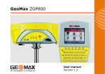
Leica GPS900
User Manual
Version 2.0
English
GPS900
Introduction
2
Introduction
Purchase
Congratulations on the purchase of a GPS900 series instrument.
This manual contains important safety directions as well as instructions for setting
up the product and operating it. Refer to "9 Safety Directions" for further information. Read carefully through the User Manual before you switch on the product.
Product
identification
The type and serial number of your product are indicated on the type plate. Enter the
type and serial number in your manual and always refer to this information when you
need to contact your agency or Leica Geosystems authorized service workshop.
Type:
_______________
Serial No.:
_______________
Symbols used in
this manual
The symbols used in this manual have the following meanings:
Type
Description
Danger
Warning
Caution
)
)
•
•
•
Introduction
Indicates an imminently hazardous situation which, if not
avoided, will result in death or serious injury.
Indicates a potentially hazardous situation or an unintended use
which, if not avoided, could result in death or serious injury.
Indicates a potentially hazardous situation or an unintended use
which, if not avoided, may result in minor or moderate injury
and/or appreciable material, financial and environmental
damage.
Important paragraphs which must be adhered to in practice as
they enable the product to be used in a technically correct and
efficient manner.
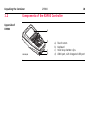
The RX900 controller is available as RX900 or as RX900c. The name RX900 is used
througout the manual and may also represent the RX900c.
A GPS900 real-time rover can only be made up of an ATX900 GG GNSS antenna
together with the RX900 controller, the GFU radio and the GHT56 holder.
A GPS900 real-time reference station can only be set up using an ATX900 GG
GNSS antenna and the RX900 controller, the GFU radio and the GEV205 cable.
GPS900
3
Introduction
)
Trademarks
4
GPS900
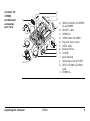
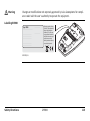
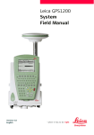
The RX900 controller.
The radio housing includes the
integrated GFU radio.
• Windows and Windows CE are a registered trademark of Microsoft Corporation
• Bluetooth is a registered trademark of Bluetooth SIG, Inc
All other trademarks are the property of their respective owners.
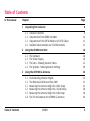
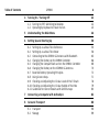
Table of Contents
In this manual
Chapter
1
Unpacking the Container
1.1
1.2
1.3
1.4
2
3
Table of Contents
Page
Container Contents
Components of the RX900 Controller
Components of the GHT56 Holder and GHT52 Clamp
Available Documentation and CD ROM Contents
8
8
10
12
13
Using the RX900 Controller
16
2.1
2.2
2.3
2.4
16
20
22
29
The
The
The
The
Keyboard
Screen Display
Icons - Showing Receiver Status
Symbols - Showing Receiver Settings
Using the ATX900 GG Antenna
32
3.1
3.2
3.3
3.4
3.5
3.6
32
33
34
36
38
40
Understanding Antenna Heights
The Mechanical Reference Plane, MRP
Measuring the Antenna Height for a Pillar Setup
Measuring the Antenna Height for a Tripod Setup
Measuring the Antenna Height for a Pole Setup
The LED Indicators on the ATX900 GG Antenna
GPS900
5
GPS900
Table of Contents
4
6
Turning On / Turning Off
42
4.1
4.2
42
45
Turning On/Off, Switching to Desktop
Operating by Keyboard or Touch Screen
5
Understanding the Main Menu
46
6
Setting Up and Starting Up
50
6.1
6.2
6.3
6.4
6.5
6.6
6.7
6.8
6.9
6.10
6.11
50
56
65
66
68
70
72
73
76
79
80
Setting Up as a Real-Time Reference
Setting Up as a Real-Time Rover
Connecting to the ATX900 GG Antenna with Bluetooth
Changing the Battery on the RX900 Controller
Changing the CompactFlash card on the RX900c Controller
Changing the Battery on the ATX900 GG Antenna
Essential Battery Operating Principles
Using Licence Keys
Checking and Adjusting the Circular Level of the Tribrach
Checking and Adjusting the Circular Bubble of the Pole
Guidelines for Correct Results with GNSS Surveys
7
Connecting a Computer with ActiveSync
82
8
Care and Transport
88
8.1
8.2
88
89
Transport
Storage
8.3
9
Cleaning and Drying
Safety Directions
9.1
9.2
9.3
9.4
9.5
9.6
9.7
9.8
9.9
General Introduction
Intended Use
Limits of Use
Responsibilities
International Warranty, Software Licence Agreement
End User Licence Agreement EULA
Hazards of Use
Electromagnetic Compatibility EMC
FCC Statement, Applicable in U.S.
10 Technical Data
92
93
95
96
97
99
102
111
114
120
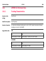
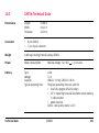
10.1 RX900 Technical Data
10.2 ATX900 GG Technical Data
10.2.1
Tracking Characteristics
10.2.2
Accuracy
10.2.3
Technical Data
10.3 GHT56 Technical Data
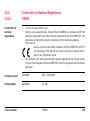
10.4 Conformity to National Regulations
10.4.1
RX900
10.4.2
ATX900 GG
Index
Table of Contents
90
92
120
124
124
127
128
131
133
133
135
138
GPS900
7
Unpacking the Container
8
GPS900
1
Unpacking the Container
1.1
Container Contents
Description
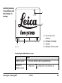
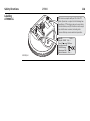
The main components required for the cableless GNSS real-time system are
combined in one transport container.
Container for
GPS900
and delivered
accessories
part 1 of 2
a
b
c
e
f
d
g
h
GPS900_002
a)
b)
c)
d)
e)
f)
Radio housing
GRT146 carrier
GPS900 User Manual
RX900
Height hook
GHT58 tripod bracket
for radio housing
g) Tribrach
h) Adjusting pin
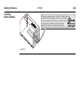
Container for
GPS900
and delivered
accessories
part 2 of 2
e
f
g
a
Leica
GPS900
Leica
b
GPS900
h
c
i
d
j
k
l
GPS900_001
Unpacking the Container
GPS900
a) GEB211 batteries for ATX900
GG and RX900
b) GEV205 Y-cable
c) ATX900 GG
d) GHT56 holder for RX900
e) Stylus for touch screen
f) GHT52 clamp
g) Radio antennas
h) CD ROM
i) Radio housing
j) Tightening screw for GHT52
k) GEV173 ATX900 GG-RX900
cable
l) ATX900 GG
9
Unpacking the Container
1.2
10
GPS900
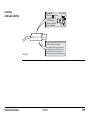
Components of the RX900 Controller
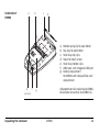
Upperside of
RX900
a
b
GPS900_003
c
d
a)
b)
c)
d)
Touch screen
Keyboard
Hand strap bottom clips
LEMO port, with integrated USB port
Underside of
RX900
b
a
c
d
a)
b)
c)
d)
e)
f)
g)
e
f
A Bluetooth port is included inside RX900,
to facilitate connectivity to ATX900 GG.
g
GPS900_004
Unpacking the Container
Bottom spring clip for pole holder
Top clips for pole holder
Hand strap top clips
Stylus for touch screen
Hand strap bottom clips
LEMO port, with integrated USB port
Battery compartment
For RX900c with CompactFlash card
compartment
GPS900
11
12
GPS900
Unpacking the Container
1.3
Components of the GHT56 Holder and GHT52 Clamp
Components of the
GHT56 holder and
GHT52 clamp
The GHT56 holder and GHT52 clamp both consist of a number of components, as
shown in the diagram.
c
d
GHT52 clamp
e a) Pole clamp
f
b) Clamp bolt
a
g GHT56 holder
b
GPS900_070
hi
j
c) Tightening screw
d) Mounting arm
e) Clip-on-contacs for
connecting RX900
f) LED
g) Mounting plate
h) Battery compartement
i) Locking mechanism for
battery
j) Space for clip-on-housing
with LEMO port
1.4
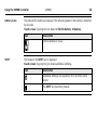
Available Documentation and CD ROM Contents
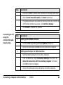
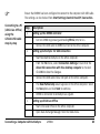
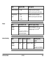
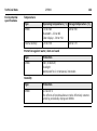
Available
product manuals
Three product manuals are available for GPS900:
Name of
manual
Description of manual
User
Manual
All instructions required in order to operate the
product to a basic level are contained in the
User Manual. Provides an overview of the
product together with technical data and safety
directions.
Manual format
PRINTED PDF
Quick Guide Provides an overview of the product and
selected program functions.
9
9
9
Tutorial
Manual
Step-by-step instructions, explaining/showing
how to complete various survey tasks.
9
Technical
Reference
Manual
Overall comprehensive guide to the product and
program functions. Included are detailed
descriptions of special software/hardware
settings and software/hardware functions
intended for technical specialists.
9
Unpacking the Container
GPS900
13
Unpacking the Container
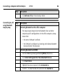
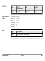
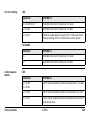
CD ROM contents
GPS900
The GPS900 CD ROM contains software and documentation specific to GPS900:
Type
Description
Software
System software
Language software
Application programs
GPS900 Simulation
Documentation
GPS900 User Manual
GPS900 Tutorial Manual
GPS900 Technical Reference Manual
GPS900 Equipment List
14
Unpacking the Container
GPS900
15
16
GPS900
Using the RX900 Controller
2
Using the RX900 Controller
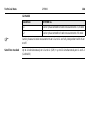
2.1
The Keyboard
Keyboard display
ESC
j
PROG
OFF
F1
Q
W
A
F2
E
S
Z
F
C
F8
F4
T
D
X
F7
F3
R
G
V
F5
Y
U
H
B
SPACE
F9
F6
I
J
N
F10
K
L
CAPS
M
F11
SHIFT
7
8
4
5
1
6
2
0
PgUp
9
PgDn
3
.
F12
a
b
c
d
e
f
g
ESC
CE
USER
PROG
OFF
GPS900_005
P
O
ON
ON
h
i
a)
b)
c)
d)
e)
f)
g)
h)
i)
j)
Function keys F1-F6
Alpha keys
CAPS
Hot keys F7-F12
SPACE, SHIFT
ENTER
Arrow keys
CE, ESC, USER, PROG
Numeric keys
Windows key symbol.
This is the Microsoft flag logo
located between PROG and ESC.
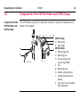
Special Keys
Key
Function
Hot keys F7-F12
User definable keys for access to any application, configuration or function.
PROG (ON)
If the receiver is off: press and hold for 2 s to turn it on.
If the receiver is on: press at any time to access the Programs
screen, where a program can be selected.
Other Keys
USER
User definable menu for quick access anytime and access to
all STATUS panels.
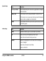
Key
Function
CAPS
Switches between upper case and lower case letters.
CE
Clears all entry at the beginning of user input.
Clears the last character during user input.
ENTER
Selects the highlighted line and leads to the next logical
menu / dialogue.
Starts the edit mode for edit fields.
Opens a choicelist.
Using the RX900 Controller
GPS900
17
Using the RX900 Controller
GPS900
Key
Function
ESC
Leaves the current menu or dialogue without storing any
changes.
18
Turns receiver off when held for 2 s in the Main Menu screen.
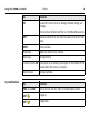
Key combinations
SHIFT
Switches between the first and the second level of function
keys.
SPACE
Enters a blank.
Arrow keys
Moves the focus on the screen.
Alpha keys
To type letters.
Function keys F1-F6
Correspond to six softkeys that appear on the bottom of the
screen when the screen is activated.
Numeric keys
To type numbers.
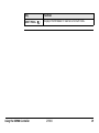
Key
Function
PROG plus USER
Turns receiver off when held in the Main Menu screen.
SHIFT
Pages up.
SHIFT
Pages down.
Key
SHIFT PROG (
Using the RX900 Controller
Function
)
Displays the Windows CE task bar and start menu.
GPS900
19
2.2
20
GPS900
Using the RX900 Controller
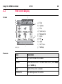
The Screen Display
Screen
f
a
b
c
g
d
h
i
e
j
GPS900_006
Elements
Type
a)
b)
c)
d)
e)
f)
g)
h)
i)
j)
Time
Caption
Title
Screen area
Message line
Icons
ESC
CAPS
SHIFT icon
Softkeys
Description
Time
The current local time is shown.
Caption
Shows location either in the Main Menu screen, under PROG
key or USER key.
Title
Name of the screen is shown.
Screen area
The working area of the screen.
Type
Description
Message line
Messages are shown for 10 s.
Icons
Shows current status information of the receiver. Can be
used with touch screen to access the subsequent screen.
ESC
Can be used with touch screen. Same functionality as the
ESC fixed key. The last operation will be undone.
CAPS
The caps mode for upper case letters is active. The caps
mode is activated and deactivated by pressing UPPER (F5)
or LOWER (F5) in some screens.
SHIFT icon
Shows the status of the SHIFT key; either first or second
level of softkeys is selected. Can be used with touch screen
and has the same functionality as the fixed key SHIFT.
Softkeys
Commands can be executed using F1 - F6 keys. The
commands assigned to the softkeys are screen dependent.
Can be used directly with touch screen.
Using the RX900 Controller
GPS900
21
22
GPS900
Using the RX900 Controller
2.3
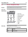
The Icons - Showing Receiver Status
Description
Icons show infomation about the current status of the receiver.
Position of the
icons on the screen
a b c
d
e f
g
h
i
GPS900_007
Position status
a)
b)
c)
d)
e)
f)
g)
h)
i)
Position status
Number of visible satellites
Contributing satellites
Real-time status
Position mode
Bluetooth
Data management
Battery
SHIFT
Displays the status of the current position.
Touch screen: Tapping the icon leads to STATUS Position.
Icon
Description
No icon
No position available.
Icon
Description
Autonomous solution available.
Code solution available.
Phase fixed solution available. The ticks indicate that an
ambiguity check is being made.
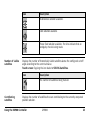
Number of visible
satellites
Displays the number of theoretically visible satellites above the configured cut off
angle according to the current almanac.
Touch screen: Tapping the icon leads to STATUS Satellites.
Icon
Description
The number of satellites being tracked.
Contributing
satellites
Displays the number of satellites that are contributing to the currently computed
position solution.
Using the RX900 Controller
GPS900
23
Using the RX900 Controller
GPS900
24
Touch screen: Tapping the icon leads to STATUS Satellites.
.
Icon
Description
When a position status icon is displayed, the number of
satellites currently used for the position computation are
shown.
If no position is currently available but satellites are being
tracked then the L1 and L2 values (GPS only) or the G and R
values (GPS & GLONASS) show how many satellites are being
tracked.
)
)
The number of contributing satellites can differ
from the number of visible satellites. This may be
either because satellites cannot be viewed or the
observations to these satellites are considered to
be too noisy to be used in the position solution.
The number of contributing GLONASS satellites
could be zero if five or more GPS satellites are used
for the position computation. The processing algorithm automatically selects the best possible set of
satellite combinations for the position computation.
A position computation with R = 0 is certainly
within the specified reliability.
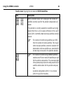
Real-time device
and
real-time status
Displays the real-time device configured to be used and its status.
Touch screen: Tapping the icon leads to STATUS Real-Time Input.
Real-time mode: Reference
An arrow pointing up indicates a reference configuration, it does not indicate if the
device is working. The arrow flashes when a real-time message is sent. When two
real-time devices are configured, then the icon for the real-time 1 device is shown.
Icon
Description
Radio transmitting
Real-time mode: Rover
An arrow pointing down indicates a rover configuration. The arrow flashes when realtime messages are received.
Icon
Description
Radio receiving.
Using the RX900 Controller
GPS900
25
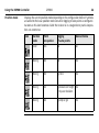
Position mode
26
GPS900
Using the RX900 Controller
Displays the current position mode depending on the configuration defined. Symbols
are added to the basic position mode icon when logging of auto points is configured.
As soon as this icon becomes visible the receiver is in a stage where practical operation can commence.
Icon
Position
mode
Point
occupation
Logging
of auto points
Move antenna
Static
Yes
No
No
Moving
No
No
Yes
Moving
No
By time
Yes
Moving
No
By distance or height Yes
or by user decision
Moving
No
By stop & go
Yes
Bluetooth
The status of each Bluetooth port and any Bluetooth connection is displayed.
Touch screen: Tapping the icon leads to STATUS Bluetooth.
Icon
Description
Bluetooth is integrated.
A Bluetooth connection is established and active.
Bluetooth connection not established. Bluetooth port 1, 2
and 3 are down.
Bluetooth connection established. Bluetooth port 1, 2 and 3
are active.
Data management
The number of lines and areas currently open in the active job is displayed.
Touch screen: Tapping the icon leads to MANAGE Data: Job Name
.
Icon
Description
The active job in Data Management.
Using the RX900 Controller
GPS900
27
Using the RX900 Controller
Battery icons
GPS900
The status of the battery is displayed. The remaining power in the battery is indicated
by six levels.
Touch screen: Tapping the icon leads to STATUS Battery & Memory.
Icon
Description
Internal battery is in use.
SHIFT
28
The status of the SHIFT key is displayed.
Touch screen: Tapping the icon shows additional softkeys.
.
Icon
Description
Additional softkeys are available in the currently visible
screen.
The SHIFT key has been pressed.
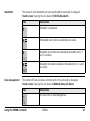
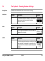
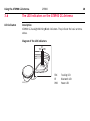
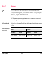
2.4
The Symbols - Showing Receiver Settings
Description
Symbols show information about current receiver settings.
Attributes
Symbol
Description
Example
The attribute symbol is displayed in the MANAGE
Codes screen to indicate codes that have
attributes attached.
Filter
Symbol
Description
Example
The filter symbol is shown on the Points page if a
stakeout filter is active.
Limits
Symbol
Description
Example
The limits symbol indicates that a defined limit has
been exceeded. For example, the exceeding of a
residual limit in the Determine Coordinate System
program.
Using the RX900 Controller
GPS900
29
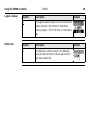
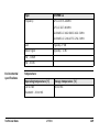
Using the RX900 Controller
Largest residual
Symbol
30
GPS900
Description
Example
The largest residual symbol is used to indicate the
largest residual in the Determine Coordinate
System program - DET C SYS Step 4: Check Residuals.
Staked out
Symbol
Description
The staked out symbol is used in the MANAGE
Data: Job Name screen to indicate points which
have been staked out.
Example
Using the RX900 Controller
GPS900
31
Using the ATX900 GG Antenna
GPS900
3
Using the ATX900 GG Antenna
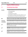
3.1
Understanding Antenna Heights
Description
•
•
32
The height of the GNSS antenna above the point consists of three components:
• the vertical height reading,
• the vertical offset,
• the vertical phase centre variations.
For most operations, pre-configured standard settings in RX900 can be used.
They automatically take the vertical phase centre variations into account.
MRP
GPS900 accepts vertical height readings to the Mechanical Reference Plane, MPR.
Vertical phase
centre variations
These are handled automatically in the standard antenna records. The antenna cali-
)
)
)
brations to determine the phase centre variations were executed by Geo++® GmbH.
Pillar setup. For other than the GRT146 carrier, the dimensions must be determined
and the vertical offset must be adapted.
Tripod setup. For height measurement devices other than the height hook, the
dimensions must be determined and the vertical offset must be adapted.
Pole setup. For other than Leica poles, the dimensions must be determined.
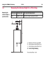
3.2
The Mechanical Reference Plane, MRP
Description
The Mechanical Reference Plane:
• is where the antenna heights are measured to.
• is where the phase centre variations refer to.
• varies for different antennas.
MRP for ATX900 GG
The MRP for ATX900 GG is shown in the diagram.
a) The mechanical reference plane is
the underside of the threaded metal
insert.
a
GPS900_60
Using the ATX900 GG Antenna
GPS900
33
3.3
Measuring the
antenna height, a
quick overview
34
GPS900
Using the ATX900 GG Antenna
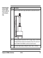
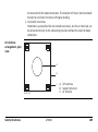
Measuring the Antenna Height for a Pillar Setup
Setup type Antenna name
The required measurement
Pillar
the vertical height reading to the MRP.
a
ATX900 GG Pillar
b
c
d
a)
b)
c)
d)
GPS900_016
Mechanical reference plane MRP
Vertical phase centre offset for L1
Vertical phase centre offset for L2
Vertical Height Reading
The Vertical offset = 0.00
Step
Description
Measure a height from the pillar benchmark to a surface on the carrier.
2.
Use the appropriate measurement from the diagram above, to determine
the height difference between the measured surface on the carrier and
where the MRP of the ATX900 GG antenna sits on the carrier.
3.
The vertical height reading = adding the values in step 1. and step 2.
36.5 mm
109 mm
1.
145.5 mm
Determining the
antenna height
with the GRT146
carrier step-bystep
GPS900_028
Using the ATX900 GG Antenna
GPS900
35
3.4
Measuring the
antenna height, a
quick overview
36
GPS900
Using the ATX900 GG Antenna
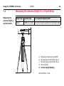
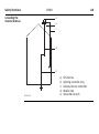
Measuring the Antenna Height for a Tripod Setup
Setup Type Antenna type
The required measurement
Tripod
the vertical height reading from the height hook.
a
ATX900 GG Tripod
b
c
d
e
GPS900_017
a)
b)
c)
d)
e)
Mechanical reference plane MRP
Vertical phase centre offset for L1
Vertical phase centre offset for L2
Vertical offset
Vertical Height Reading
Vertical offset = 0.36
Determining the
antenna height
with the height
hook step-by-step
Step
1.
Using the ATX900 GG Antenna
Description
The vertical height reading = vertical height reading from the height hook.
•
The vertical height reading is the height difference between the
ground mark and the bottom end of the height hook.
•
The vertical offset of 0.36 m is automatically stored in the antenna
setup record for a tripod setup and will automatically be taken into
account. It does not need to be entered.
GPS900
37
3.5
Measuring the
antenna height, a
quick overview
38
GPS900
Using the ATX900 GG Antenna
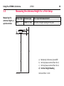
Measuring the Antenna Height for a Pole Setup
Setup Type Antenna type
The required measurement
Pole
the vertical height reading of the pole.
a
ATX900 GG Pole
b
c
d
a)
b)
c)
d)
GPS900_018
Mechanical reference plane MRP
Vertical phase centre offset for L1
Vertical phase centre offset for L2
Vertical Height Reading
Vertical offset = 0.00
Determining the
antenna height
step-by-step
Step
1.
Description
The vertical height reading =
•
•
•
Using the ATX900 GG Antenna
2.00 m for the Leica threaded aluminium pole consisting of an upper
half and a lower half.
3.00 m for the Leica threaded aluminium pole consisting of an upper
half and a lower half, with an additional 1.00 m pole section.
2.00 m for the fully extended Leica telescopic carbon-fibre pole.
GPS900
39
40
GPS900
Using the ATX900 GG Antenna
3.6
The LED Indicators on the ATX900 GG Antenna
LED indicators
Description
ATX900 GG has Light Emitting Diode indicators. They indicate the basic antenna
status.
Diagram of the LED indicators
BT
TRK PWR
K
R
T
GPS900_59
T
B
R
W
P
ON
OFF
TRK
BT
PWR
Tracking LED
Bluetooth LED
Power LED
Description of the LED indicators
IF the
is
THEN
TRK
off
No satellites are tracked.
flashing green
Less than four satellites are tracked, a position is not
yet available.
green
Enough satellites are tracked to compute a position.
red
ATX900 GG is initialising.
green
Bluetooth is in data mode and ready for connecting.
purple
Bluetooth is connecting.
blue
Bluetooth has connected.
BT
PWR
Using the ATX900 GG Antenna
flashing blue
Data is being transferred
off
Power is off.
green
Power is okay.
flashing green
Power is low. The remaining time for which enough
power is available depends on the type of survey, the
temperature and the age of the battery.
GPS900
41
Turning On / Turning Off
GPS900
42
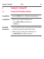
4
Turning On / Turning Off
4.1
Turning On/Off, Switching to Desktop
Turning RX900 on
•
Press and hold PROG (ON) for 2 s. (RX900 must have a power supply).
Turning RX900 off
•
RX900 can only be turned off in the Main Menu screen.
• Press the USER and PROG keys simultaneously, or
• Hold ESC for 2 s.
Putting RX900
into sleep mode
•
In sleep mode, RX900 shuts down and reduces power consumption. Rebooting
from sleep mode is quicker than a cold start after turning off.
RX900 can only be put into sleep mode in the Main Menu screen.
Press SHIFT SLEEP (F3) to put RX900 into sleep mode.
•
•
Switching between
Leica software and
the Windows CE
desktop
a
GPS 900
b
d
a) Icon to start Leica
software
b) Windows CE desktop
c) Task bar
d) Windows CE start button
c
GPS900_075
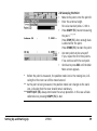
Accessing the Main Menu screen
IF
THEN
RX900 is started
•
the Leica software starts up automatically.
Windows CE
desktop is active
•
double click
Turning On / Turning Off
GPS900
to display the Leica software, or
43
IF
Leica software is
minimised
44
GPS900
Turning On / Turning Off
THEN
•
press SHIFT PROG (
•
double click
•
select GPS900 in the task bar to maximise it.
) to display the Leica software.
to maximise it, or
Accessing the Windows CE desktop
IF
THEN
Leica software is to SHIFT MINIM (F5) in the Main Menu screen.
be minimised
Leica software is to SHIFT EXIT (F6) in the Main Menu screen.
be closed
Windows CE task
bar is to be
displayed
SHIFT PROG (
).
4.2
Operating by Keyboard or Touch Screen
Operating with the
keyboard and the
touch screen
The user interface is operated either by the keyboard or by the touch screen, with
supplied stylus. The workflow is the same for keyboard and touch screen entry, the
only difference lies in the way information is selected and entered.
Operation by keyboard
Information is selected and entered using the keys. Refer to "2.1 The Keyboard" for
a detailed description of the keys on the keyboard and their function.
Operation by touch screen
Information is selected and entered on the screen using the supplied stylus.
Operation
Description
To select an item
Tap on the item.
To start the edit mode in input fields
Tap on the input field.
To highlight an item or parts of it for
editing
Drag the supplied stylus from the left to
the right.
To accept data entered into an input field Tap on the screen outside of the input
and exit the edit mode
field.
Turning On / Turning Off
GPS900
45
46
GPS900
Understanding the Main Menu
5
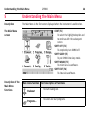
Understanding the Main Menu
Description
The Main Menu is the first screen displayed when the instrument is switched on.
CONT (F1)
To select the highlighted option and
to continue with the subsequent
screen.
SHIFT OFF (F2)
To completely turn RX900 off.
SHIFT SLEEP (F3)
To put RX900 into sleep mode.
SHIFT MINIM (F5)
To minimise Leica software.
SHIFT EXIT (F6)
To close Leica software.
The Main Menu
screen
Description of the
Main Menu
functions
Main menu function Short description of functions
Stakeout
Programs...
•
To start staking out.
•
To select and start programs.
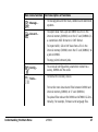
Main menu function Short description of functions
Manage...
Convert...
Config...
Tools...
Understanding the Main Menu
•
To manage jobs and their data, codelists and coordinate
systems.
•
To export data from a job on RX900 to a file in the
internal memory (RX900) or on the CF card (RX900c) in
a customised ASCII format or in DXF format.
•
To import ASCII, GSI or DXF data from a file in the
internal memory (RX900) or on the CF card (RX900c) to
a job on RX900.
•
To copy points between jobs.
•
To access all configuration parameters related to a
survey, RX900 and the radio.
•
To format the memory device.
•
To transfer non data related files between RX900 and
internal memory (RX900) or CF card (RX900c).
•
To upload files relevant for RX900 and ATX900 GG functionality, for example, firmware and language files.
GPS900
47
GPS900
Understanding the Main Menu
48
Main menu function Short description of functions
•
To perform arithmetic operations such as addition,
subtraction, multiplication, division, statistical functions, trigonometric functions, conversions or roots.
•
To view files in the internal memory (RX900) or CF card
(RX900c).
•
To manually type in or upload a licence key.
Understanding the Main Menu
GPS900
49
Setting Up and Starting Up
50
GPS900
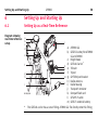
6
Setting Up and Starting Up
6.1
Setting Up as a Real-Time Reference
Diagram showing
real-time reference
setup
a
b
c
d
j
e
f
g
h
b
k
l
m
i
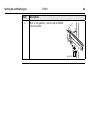
n
GPS900_010
*
a) ATX900 GG
b) GEB211 battery for ATX900
GG and RX900
c) Height hook
d) GRT146 Carrier*
e) Tribrach
f) Tripod
g) GHT58 tripod bracket
h) Radio antenna
i) Radio housing
j) Transport container
k) CompactFlash card
l) GEV205 Y-cable
m) GEB171 external battery
The GRT146 carrier has a screw fitting. ATX900 GG fits directly onto this fitting.
Setup and Startup
for
real-time reference
step-by-step
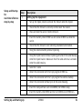
Step
1.
Setting Up and Starting Up
Description
Setting Up the Equipment
•
Set up the tripod, mount and level the tribrach onto the tripod.
•
Check that the tribrach is correctly centred over the marker.
•
Place and lock the carrier into the tribrach.
•
Insert the battery into ATX900 GG and screw ATX900 GG onto the
carrier.
•
Check that the tribrach is still correctly positioned and levelled.
•
Hang the external battery onto a tripod leg.
•
Hang the tripod bracket onto a tripod leg and attach the radio housing
onto the tripod bracket. Make sure that the radio antenna is screwed
onto the radio housing.
•
Take the Y-cable.
•
Attach the connector with the 8 pin plug to ATX900 GG.
•
Attach the connector with the 5 pin plug to the external battery.
•
Attach the connector without pins to the radio housing.
•
Insert the CompactFlash card into RX900 (for RX900c only).
•
Insert the battery into RX900 and turn on RX900 and ATX900 GG.
GPS900
51
Step
2.
52
GPS900
Setting Up and Starting Up
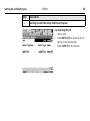
Description
Starting Up with the Setup Reference Program
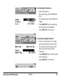
2.a Selecting the Job
• Select a Job.
• Press DATA (F5) to check all of the
points in the selected job.
• Press CONT (F1) to continue.
2.b Selecting the Antenna
•
•
•
Select the antenna.*
For a pillar setup, select ATX900 GG
Pillar.
For a tripod setup, select ATX900 GG
Tripod.
Press SRCH (F4) to start searching
for the antenna, via Bluetooth.
Press CONT (F1) to continue.
2.c Setting the Radio Channel**
• Enter the radio channel. It is important to remember that the radio at
the reference and the radio at the
rover must be set to the same
frequency.
Press SCAN (F5) to scan for the radio
at the reference.
• Press CONT (F1) to continue.
Setting Up and Starting Up
GPS900
53
Setting Up and Starting Up
54
GPS900
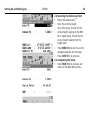
2.d Selecting the Reference Point
Select the known point.***
Enter the antenna height.
For a pillar setup, this will be the
vertical height reading to the MRP.
For a tripod setup, this will be the
vertical height reading from the
height hook.
• Press HERE (F4) to use the current
navigated position for the setup.
• Press CONT (F1) to continue.
2.e Completing the Setup
• Press FNSH (F1) to continue and
return to the Main Menu screen.
•
•
*
Refer to "3 Using the ATX900 GG Antenna" for further information on antennas
and antenna heights.
** Depending on the radio attached the screen content slightly differs.
***When setting the reference point for the setup, the selected point must be able
to be viewed as WGS1984 coordinates.
Setting Up and Starting Up
GPS900
55
Setting Up and Starting Up
6.2
Diagram showing
real-time rover
setup
56
GPS900
Setting Up as a Real-Time Rover
a
b
g
c
b
h
d
i
e
b
j
f
GPS900_026
a) ATX900 GG
b) GEB211 battery for ATX900 GG,
RX900 and radio
c) Compression lock of the pole
d) GHT56 holder for RX900
e) Snap-lock of the pole
f) GLS30 telescopic carbon-fibre pole
g) Radio antenna
h) CompactFlash card
i) RX900
j) Radio
Setup and Startup
step-by-step
Step
1.
Setting Up and Starting Up
Description
Setting Up the Equipment
•
Insert the battery into ATX900 GG.
•
Screw ATX900 GG onto the top of the telescopic pole.
•
Ensure that the compression lock is not clamped.
•
Fully extend the telescopic pole and ensure that the snap-lock clicks
into its position. The snap-lock ensures that there is no slipping of the
telescopic pole.
•
Clamp the compression lock. The compression lock maintains straightness.
•
Remove the plastic sleeve from the clamp. Slide the clamp onto the
bottom part of the telescopic pole.
•
Fix the holder to the clamp with the tightening screw. Before tightening, ensure that the holder is at a comfortable working height and
angle. This can be achieved by sliding the clamp along the pole and
rotating the holder about the clamp. Tighten the tightening screw.
•
Insert the CompactFlash card into RX900 (for RX900c only).
•
Insert the battery into RX900.
GPS900
57
Step
2.
58
GPS900
Setting Up and Starting Up
Description
•
Clip RX900 onto the holder and lock into position. Refer to "Attaching
RX900 to the GHT56 holder step-by-step" for further information.
•
Turn on ATX900 GG and RX900.
Starting Up with the Survey Program
2.a
•
•
•
Selecting the Job
Select the Job Default.
Select the WGS1984 coord system.
Press CONT (F1) to continue.
2.b Surveying the Point
• Move to the point, enter the point ID.
• Enter the antenna height.
For Leica standard poles = 2.00 m.
• Press OCUPY (F1) to start measuring
•
•
the point.*,**,***
Press STOP (F1) when enough data
is collected for the point.
Press STORE (F1) to store the point.
Are more points to be surveyed?
If yes, repeat the first three points.
If no, continue with the next point.
Continue to press ESC until the Main
Menu screen appears.
*
Before the point is measured, the position mode icon is the moving icon, indicating that the rover can still be moved around.
** As the point is being measured, the position mode icon changes to the static
icon, indicating that the rover should remain stationary.
***SHIFT QUIT (F6) always terminates the survey operation. In this case all data
collected since pressing OCUPY (F1) is lost.
Setting Up and Starting Up
GPS900
59
GPS900
Setting Up and Starting Up
Attaching the
GHT56 holder to
the left or right
side of the pole
60
The GHT56 holder can be attached either to the left side or right side of the pole.
Step
)
Description
Refer to "1.3 Components of the GHT56 Holder and GHT52 Clamp" for
further information on the holder.
1.
Remove the thumb screw from the mounting plate.
2.
Remove the mounting arm from the mounting plate and re-position it.
3.
Re-fix the mounting arm to the mounting plate with the tightening screw.
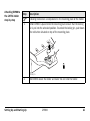
Attaching RX900 to
the GHT56 holder
step-by-step
Step
)
1.
Description
A locking mechanism is incorporated in the mounting plate of the holder.
Before RX900 is placed onto the mounting plate ensure that the locking
pin is put into the unlocked position. To unlock the locking pin, push down
the red button situated on top of the mounting plate.
GPS900_072
2.
Setting Up and Starting Up
Hold RX900 above the holder and lower the end into the holder.
GPS900
61
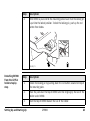
Step
3.
62
GPS900
Setting Up and Starting Up
Description
Apply slight pressure in a downward direction and
then lower the top part of RX900 until the unit is
clicked into the holder. The guides of the holder
aid in this action.
GPS900_008
Step
4.
Description
After RX900 is placed onto the mounting plate ensure that the locking pin
is put into the locked position. To lock the locking pin, push up the red
button from below.
GPS900_071
Detaching RX900
from the GHT56
holder step-bystep
Step
Description
1.
Unlock the locking pin by pushing down the red button situated on top of
the mounting plate.
2.
Place the palm over the top of RX900 until the fingers grip the bar of the
holder under RX900.
3.
Push the top of RX900 toward the bar of the holder.
Setting Up and Starting Up
GPS900
63
Step
4.
64
GPS900
Setting Up and Starting Up
Description
While in this position, raise the top of RX900
from the holder.
2
1
GPS900_009
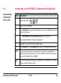
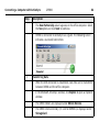
6.3
Communicating
via Bluetooth
step-by-step
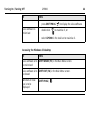
Connecting to the ATX900 GG Antenna with Bluetooth
Step
1.
Description
Select Main Menu:
2.
Select Comm: Bluetooth.
3.
Press SRCH (F4) to search for Bluetooth devices. The ATX900 GG antenna
must be turned on.
4.
The CONFIGURE Search Bluetooth Device screen appears.
5.
Highlight and select the antenna to be used.
6.
Press CONT (F1). Press CONT (F1) to return to the Main Menu screen.
All available Bluetooth devices are displayed.
)
)
Setting Up and Starting Up
If the antenna selected is connected for the first time, a Windows CE
authentication request comes up. Type in 0000 as identification number
for Leica’s Bluetooth and click OK.
Once the Bluetooth connection is established, the Bluetooth LED on the
antenna starts flashing in blue.
GPS900
65
GPS900
Setting Up and Starting Up
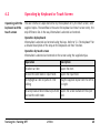
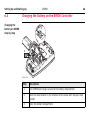
6.4
Changing the Battery on the RX900 Controller
Changing the
battery on RX900
step-by-step
2
4
5
3
6
GPS900_073
f
Step
Description
1.
Turn RX900 over to gain access to the battery compartment.
2.
Push the slide fastener in the direction of the arrow with the open-lock
symbol.
3.
Open the battery compartment.
66
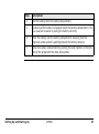
Step
Description
4.
Pull the battery from the battery compartment.
5.
A polarity of the battery is displayed inside the battery compartment. This
is a visual aid to assist in placing the battery correctly.
6.
Place the battery into the battery compartment, ensuring that the
engraved arrow symbol is pointing toward the battery contacts.
7.
Close the battery compartment by pushing the slide fastener in the direction of the arrow with the close-lock symbol.
Setting Up and Starting Up
GPS900
67
GPS900
Setting Up and Starting Up
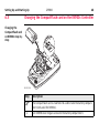
6.5
68
Changing the CompactFlash card on the RX900c Controller
Changing the
CompactFlash card
on RX900c step-bystep
2
4
3
11
10
GPS900_082
f
Step
)
1.
Description
The CompactFlash card is inserted into a slot inside the battery compartment (only valid for RX900c).
Turn RX900c over to gain access to the battery compartment.
Step
Description
2.
Push the slide fastener in the direction of the arrow with the open-lock
symbol.
3.
Open the battery compartment.
4.
Pull the battery from the battery compartment.
5.
)
The card should be held with the label for the care instructions
upwards and the contacts facing the slot.
Slide the card firmly into the slot until it clicks into position.
6.
Place the battery into the battery compartment, ensuring that the
engraved arrow symbol is pointing toward the battery contacts.
7.
Close the battery compartment by pushing the slide fastener in the direction of the arrow with the close-lock symbol.
8.
To remove the card, open the cover of the battery compartment.
9.
Pull the battery from the battery compartment.
10.
Press the eject button on the right side of the card slot twice.
11.
Pull out the CompactFlash card and close the compartment cover.
Setting Up and Starting Up
GPS900
69
6.6
70
GPS900
Setting Up and Starting Up
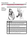
Changing the Battery on the ATX900 GG Antenna
Changing the
battery on ATX900
GG step-by-step
2
3
4
5
GPS900_012
Step
Description
1.
Turn ATX900 GG over to gain access to the battery compartment.
2.
Open the battery compartment by pushing the slide fastener in the direction of the arrow with the open-lock symbol.
3.
Pull out the battery housing. The battery is attached to the housing.
4.
Hold the battery housing and pull the battery from the battery housing.
5.
A polarity of the battery is displayed inside the battery housing. This is a
visual aid to assist in placing the battery correctly.
Step
Description
6.
Place the battery onto the battery housing, ensuring that the contacts are
facing outward. Click the battery into position.
7.
Close the battery compartment by pushing the slide fastener in the direction of the arrow with the close-lock symbol.
Setting Up and Starting Up
GPS900
71
Setting Up and Starting Up
6.7
)
)
GPS900
72
Essential Battery Operating Principles
Primary Use/Charging
• The battery must be charged prior to using it for the first time because it is delivered with an energy content as low as possible.
• For new batteries or batteries that have been stored for a long time (> three
months), it is effectual to make only one charge/discharge cycle.
• For Li-Ion batteries, a single discharging and charging cycle is sufficient. We
recommend carrying out the process when the battery capacity indicated on the
charger or on a Leica Geosystems product deviates significantly from the actual
battery capacity available.
• The permissible temperature range for charging is between 0°C to +40°C/ +32°F
to +104°F. For optimal charging we recommend charging the batteries at a low
ambient temperature of +10°C to +20°C/+50°F to +68°F if possible.
• It is normal for the battery to become warm during charging. Using the chargers
recommended by Leica Geosystems, it is not possible to charge the battery if the
temperature is too high.
Operation/Discharging
• The batteries can be operated from -20°C to +55°C/-4°F to +131°F.
• Low operating temperatures reduce the capacity that can be drawn; very high
operating temperatures reduce the service life of the battery.
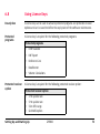
6.8
Using Licence Keys
Description
A licence key can be used to activate protected programs and protected receiver
options and can be used to define the expiry date of the software maintenance.
Protected
programs
A licence key is required for the following protected programs:
Protected receiver
option
Protected programs
•
DTM Stakeout
•
DXF Export
•
Reference Line
•
RoadRunner
•
Volume Calculations
A licence key is required for the following protected receiver option:
Protected receiver option
•
•
•
•
2 Hz update rate
5 Hz update rate
5 km RTK range
GLONASS option
Setting Up and Starting Up
GPS900
73
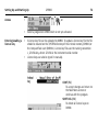
Setting Up and Starting Up
Access
Entering/Loading a
licence key
•
74
GPS900
, or
•
Select a program on RX900 which is not yet activated.
•
A licence key file can be uploaded to RX900. To upload a licence key file the file
should be located on the \SYSTEM directory of the internal memory (RX900) or
the CompactFlash card (RX900c). Licence key files use the naming convention
L_123456.key, where 123456 is the instrument serial number.
Licence keys can also be typed in manually.
•
CONT (F1)
To accept changes and return to
the Main Menu screen or
continue with the program.
SHIFT DEL (F4)
To delete all licence keys on
RX900.
Field
Description of Field
Method
•
The method used to input the licence key to activate the program
or the protected options or the software maintenance.
•
Upload Key File. The licence key file is uploaded from the
internal memory (RX900) or the CompactFlash card (RX900c). The
licence key file must be stored in the \SYSTEM directory in the
internal memory (RX900) or the CompactFlash card (RX900c).
•
Manual Entry of Key. Allows the licence key to be typed in
manually.
•
Available for <Method: Manual Entry of Key>. The licence key
required to activate a program. Entry is not case sensitive.
Key
The next step
IF a licence THEN
key is to be
uploaded
select the method used to input the licence key and press CONT (F1).
deleted
press SHIFT DEL (F4).
Setting Up and Starting Up
GPS900
75
Setting Up and Starting Up
GPS900
76
6.9
Checking and Adjusting the Circular Level of the Tribrach
Description
•
•
Equipment
checklist
The adjustable circular level on the tribrach is used to level the ATX900 GG
antenna over the observation point. An incorrectly adjusted circular level means
that the ATX900 GG antenna is not properly positioned over the point, which
means that another point on the ground is observed.
The tribrach should be checked and adjusted:
• at regular periods,
• before the first use,
• after long periods of transport,
• after long periods of work,
• if the temperature changes by more than 20 °C.
The required equipment for the checking and adjusting of the circular level are:
• Tripod,
• Tribrach,
• A carrier, with a precision bubble checked and adjusted or a TPS instrument,
• Adjusting pin.
Checking
and adjusting
the circular level
step-by-step
Step
Description
1.
Set up the tripod.
2.
Screw the tribrach onto the tripod.
3.
Fix the carrier/instrument onto the tribrach.
4.
Level the tribrach using the precision bubble on the carrier or the precision
bubble on the instrument.
5.
Is the circular level on the tribrach centered and not extended beyond the
enscribed circle?
6.
Setting Up and Starting Up
•
If yes, no adjustment is required. The procedure is finished.
•
If no, the bubble requires adjusting. Continue with step 6.
Remove the carrier/instrument.
GPS900
77
Step
7.
78
GPS900
Setting Up and Starting Up
Description
Centre the circular level using the
adjustment pin in conjunction with
the adjustment screws on the
underside of the casing of the
circular level.
GPS900_035
8.
Fix the carrier/instrument onto the tribrach.
9.
Repeat steps 4. to 5.
6.10
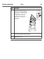
Checking and Adjusting the Circular Bubble of the Pole
Checking
and adjusting
the circular bubble
It is important that the adjustable circular bubble of the pole is kept in adjustment.
Whenever the GPS900 equipment is sent for servicing to a Leica Geosystems authorized service workshop, it is recommended that the pole is also sent for servicing.
Setting Up and Starting Up
GPS900
79
Setting Up and Starting Up
GPS900
80
6.11
Guidelines for Correct Results with GNSS Surveys
Undisturbed
satellite signal
reception
Successful GNSS surveys require undisturbed satellite signal reception, especially at
the receiver which serves as a reference. Set up the receivers in locations which are
free of obstructions such as trees, buildings or mountains.
Steady antenna for
static surveys
For static surveys, the antenna must be kept perfectly steady throughout the whole
occupation of a point. Put the antenna on a tripod or pillar.
Centred and
levelled antenna
Centre and level the antenna precisely over the marker.
Setting Up and Starting Up
GPS900
81
Connecting a Computer with ActiveSync
GPS900
82
7
Connecting a Computer with ActiveSync
Description of
ActiveSync
To transfer data to or from the office computer, the RX900 controller must be
connected to the office computer (optional for the RX900 controller with color
screen) using Microsoft ActiveSync. Microsoft ActiveSync is the synchronization software for Windows mobile-based pocket computers.
Installing
ActiveSync
Before data can be transferred, the ActiveSync software must first be installed on
the office computer. The ActiveSync software is freeware and is supplied on the
GPS900 CD ROM. Translated versions can be downloaded from the Microsoft website.
Installing the
USB Driver
using the
GEV161 USB cable
step-by-step
Step
)
Description
This procedure is only required when connecting for the first time.
1.
Start the office computer.
2.
Turn on RX900 by pressing and holding PROG (ON) for 2 s.
3.
Connect the USB cable to RX900 and to the office computer.
4.
Installing the USB driver
•
The Found New Hardware Wizard appears on the office computer.
Select the No option (Windows Updates), click Next to continue.
•
Select Install from a list or specific location, click Next to continue.
Step
Description
•
Connecting to a PC
using the
GEV161 USB cable
step-by-step
Step
1.
2.
Insert the GPS900 CD ROM, which contains the necessary USB driver.
•
Select Search removable media, click Next to continue.
•
The system will search and install the USB driver from the CD ROM. A
confirmation window may appear, click Continue Anyway.
•
Click Finish to complete the process.
Description
Setting up the RX900 controller
•
Turn on RX900 by pressing and holding PROG (ON) for 2 s.
•
Connect the USB cable to RX900 but not to the office computer.
Setting up ActiveSync for USB connection
•
Start Microsoft ActiveSync on the office computer.
•
From the File menu, select Connection Settings. Ensure that the
Allow USB connection with this desktop computer is checked.
Click OK to close the dialogue.
•
Connect the USB cable into a USB port on the office computer.
Connecting a Computer with ActiveSync
GPS900
83
Connecting a Computer with ActiveSync
Step
3.
GPS900
84
Description
•
The New Partnership wizard appears on the office computer. Select
the No option and click Next to continue.
•
RX900 is connected to ActiveSync as a guest. The following screen
indicates a successful connection.
Transferring Data
•
When the USB connection is established, data files can be transferred
between RX900 and the office computer.
•
In the Microsoft ActiveSync window, click Explore to open an Explorer
window.
•
The RX900 folders are displayed under Mobile Devices.
•
The RX900 internal memory (CF card for RX900c) is displayed under
StorageCard.
)
Connecting to a PC
(LEICA Geo Office)
using the
GEV161 USB cable
step-by-step
Ensure that RX900 has been configured to connect to the computer with USB cable.
The settings can be checked from Start/Settings/Control Panel/PC Connection.
Step
1.
2.
3.
Description
Setting up the RX900 controller
•
Turn on RX900 by pressing and holding PROG (ON) for 2 s.
•
Connect the USB cable to RX900 but not to the office computer.
Setting up ActiveSync for USB connection
•
Start Microsoft ActiveSync on the office computer.
•
From the File menu, select Connection Settings. Ensure that the
Allow USB connection with this desktop computer is checked.
Click OK to close the dialogue.
•
Connect the USB cable into a USB port on the office computer.
•
The New Partnership wizard appears on the office computer. Select
the No option and click Next to continue.
•
RX900 is connected to ActiveSync as a guest.
Setting up LEICA Geo Office
•
Start LEICA Geo Office on the office computer.
•
Open Data Exchange Manager from the Tools menu.
Connecting a Computer with ActiveSync
GPS900
85
Connecting a Computer with ActiveSync
Step
Description
•
Connecting to a PC
using Bluetooth
step-by-step
Step
1.
GPS900
Click Refresh (F5) on the ActiveSync folder.
Description
Activating Bluetooth on the office computer
•
The steps required depend on the Bluetooth driver and other
computer specific configurations. On the office computer, always
ensure that:
• the correct COM port is defined.
• the COM port is configured as incoming, which allows Bluetooth
devices to detect the computer.
2.
Activating Bluetooth on RX900
•
Turn on RX900 by pressing and holding PROG (ON) for 2 s.
•
Go to Start/Settings/Control Panel/Bluetooth Device.
•
Click Scan Device.
•
Highlight the service required in the Untrusted box.
•
Click the - -> arrow to move the service to the Trusted box.
86
Step
3.
Description
•
Highlight the service required in the Trusted box.
•
Right mouse click to access the context menu.
•
Tick Active.
•
Go to Start/Settings/Control/System/Device Name to give RX900 a
specific name.
•
Go to Start/Settings/Control Panel/PC Connection.
•
Select Bluetooth from the combo box.
•
Go to Start/Programs/Communication/ActiveSync to initialise the
communication.
•
As soon as the communication is initialised on RX900, ActiveSync
establishes the link between the office computer and RX900.
Setting up LEICA Geo Office
•
Start LEICA Geo Office on the office computer.
•
Open Data Exchange Manager from the Tools menu.
•
Click Refresh (F5) on the ActiveSync folder.
Connecting a Computer with ActiveSync
GPS900
87
GPS900
Care and Transport
88
8
Care and Transport
8.1
Transport
Transport in a road
vehicle
Never carry the product loose in a road vehicle, as it can be affected by shock and
vibration. Always carry the product in its transport container and secure it.
Shipping
When transporting the product by rail, air or sea, always use the complete original
Leica Geosystems packaging, transport container and cardboard box, or its equivalent, to protect against shock and vibration.
Shipping, transport
of batteries
When transporting or shipping batteries, the person in charge of the product must
ensure that the applicable national and international rules and regulations are
observed. Before transportation or shipping, contact your local passenger or freight
transport company.
8.2
Storage
Product
Respect the temperature limits when storing the equipment, particularly in summer
if the equipment is inside a vehicle. Refer to "10 Technical Data" for information
about temperature limits.
Li-Ion batteries
•
•
•
•
•
•
Care and Transport
Refer to "10 Technical Data" for information about storage temperature range.
A storage temperature range of -20 to +30°C/-4 to 68°F in a dry environment is
recommended to minimise self-discharging of the battery.
At the recommended storage temperature range, batteries containing a 10% to
50% charge can be stored for up to one year. After this storage period the
batteries must be recharged.
Remove batteries from the product and the charger before storing.
After storage recharge batteries before using.
Protect batteries from damp and wetness. Wet or damp batteries must be dried
before storing or use.
GPS900
89
Care and Transport
GPS900
90
8.3
Cleaning and Drying
Product
Use only a clean, soft, lint-free cloth for cleaning. If necessary, moisten the cloth with
water or pure alcohol. Do not use other liquids; these may attack the polymer components.
Damp products
Dry the product, the transport container, the foam inserts and the accessories at a
temperature not greater than 40°C / 108°F and clean them. Do not repack until
everything is completely dry.
Cables and plugs
Keep plugs clean and dry. Blow away any dirt lodged in the plugs of the connecting
cables.
Care and Transport
GPS900
91
GPS900
Safety Directions
9
Safety Directions
9.1
General Introduction
Description
•
•
92
The following directions should enable the person responsible for the product,
and the person who actually uses the equipment, to anticipate and avoid operational hazards.
The person responsible for the product must ensure that all users understand
these directions and adhere to them.
9.2
Intended Use
Permitted use
•
•
•
•
•
Adverse use
•
•
•
•
•
•
•
•
•
•
Safety Directions
Measuring raw data and computing coordinates using carrier phase and code
signal from GNSS (Global Navigation Satellite System) satellites.
Carrying out measurement tasks using various GNSS measuring techniques.
Recording GNSS and position related data.
Computation and evaluation by means of software.
Data exchange via wireless communication.
Use of the product without instruction.
Use outside of the intended limits.
Disabling safety systems.
Removal of hazard notices.
Opening the product using tools, for example screwdriver, unless this is specifically permitted for certain functions.
Modification or conversion of the product.
Use after misappropriation.
Use of products with obviously recognizable damages or defects.
Use with accessories from other manufacturers without the prior explicit
approval of Leica Geosystems.
Inadequate safeguards at the surveying site, for example when measuring on
roads.
GPS900
93
GPS900
Safety Directions
•
Warning
94
Controlling of machines, moving objects or similar monitoring application without
additional control- and safety installations.
Adverse use can lead to injury, malfunction and damage.
It is the task of the person responsible for the equipment to inform the user about
hazards and how to counteract them. The product is not to be operated until the user
has been instructed on how to work with it.
9.3
Limits of Use
Environment
Suitable for use in an atmosphere appropriate for permanent human habitation: not
suitable for use in aggressive or explosive environments.
Danger
Safety Directions
Local safety authorities and safety experts must be contacted before working in
hazardous areas, or in close proximity to electrical installations or similar situations
by the person in charge of the product.
GPS900
95
GPS900
Safety Directions
96
9.4
Responsibilities
Manufacturer of
the product
Leica Geosystems AG, CH-9435 Heerbrugg, hereinafter referred to as Leica Geosystems, is responsible for supplying the product, including the user manual and original
accessories, in a completely safe condition.
Manufacturers of
non
Leica Geosystems
accessories
The manufacturers of non Leica Geosystems accessories for the product are responsible for developing, implementing and communicating safety concepts for their
products, and are also responsible for the effectiveness of those safety concepts in
combination with the Leica Geosystems product.
Person in charge of
the product
The person in charge of the product has the following duties:
• To understand the safety instructions on the product and the instructions in the
user manual.
• To be familiar with local regulations relating to safety and accident prevention.
• To inform Leica Geosystems immediately if the product and the application
becomes unsafe.
• To ensure that the national laws, regulations and conditions for the operation of
radio transmitters are respected.
Warning
The person responsible for the product must ensure that it is used in accordance with
the instructions. This person is also accountable for the training and the deployment
of personnel who use the product and for the safety of the equipment in use.
9.5
International Warranty, Software Licence Agreement
International
Warranty
The International Warranty can be downloaded from the Leica Geosystems home
page at http://www.leica-geosystems.com/internationalwarranty or received from
your Leica Geosystems dealer.
Software Licence
Agreement
This product contains software that is preinstalled on the product, or that is supplied
to you on a data carrier medium, or that can be downloaded by you online pursuant
to prior authorization from Leica Geosystems. Such software is protected by copyright and other laws and its use is defined and regulated by the Leica Geosystems
Software Licence Agreement, which covers aspects such as, but not limited to, Scope
of the Licence, Warranty, Intellectual Property Rights, Limitation of Liability, Exclusion
of other Assurances, Governing Law and Place of Jurisdiction. Please make sure, that
at any time you fully comply with the terms and conditions of the Leica Geosystems
Software Licence Agreement.
Such agreement is provided together with all products and can also be found at the
Leica Geosystems home page at http://www.leica-geosystems.com/swlicense
or your Leica Geosystems dealer.
You must not install or use the software unless you have read and accepted the
terms and conditions of the Leica Geosystems Software Licence Agreement. Installation or use of the software or any part thereof, is deemed to be an acceptance of all
the terms and conditions of such licence agreement. If you do not agree to all or
Safety Directions
GPS900
97
Safety Directions
GPS900
98
some of the terms of such licence agreement, you may not download, install or use
the software and you must return the unused software together with its accompanying documentation and the purchase receipt to the dealer from whom you
purchased the product within ten (10) days of purchase to obtain a full refund of the
purchase price.
9.6
End User Licence Agreement EULA
EULA terms
•
•
•
Safety Directions
You have acquired a device RX900 that includes software licenced by Leica
Geosystems from an affiliate of Microsoft Corporation ("MS"). Those installed
software products of MS origin, as well as associated media, printed materials,
and "online" or electronic documentation ("SOFTWARE") are protected by international intellectual property laws and treaties. The SOFTWARE is licenced, not
sold. All rights reserved.
IF YOU DO NOT AGREE TO THIS END USER LICENCE AGREEMENT ("EULA"), DO NOT
USE THE DEVICE OR COPY THE SOFTWARE, INSTEAD, PROMPTLY CONTACT Leica
Geosystems FOR INSTRUCTIONS ON RETURN OF THE UNUSED DEVICE(S) FOR A
REFUND. ANY USE OF THE SOFTWARE, INCLUDING BUT NOT LIMITED TO USE
ON THE DEVICE, WILL CONSTITUTE YOUR AGREEMENT TO THIS EULA (OR
RATIFICATION OF ANY PREVIOUS CONSENT).
GRANT OF SOFTWARE LICENCE. This EULA grants you the following licence:
• You may use the SOFTWARE only on the DEVICE.
• NOT FAULT TOLERANT. THE SOFTWARE IS NOT FAULT TOLERANT. Leica
Geosystems HAS INDEPENDENTLY DETERMINED HOW TO USE THE SOFTWARE
IN THE DEVICE, AND MS HAS RELIED UPON Leica Geosystems TO CONDUCT
SUFFICIENT TESTING TO DETERMINE THAT THE SOFTWARE IS SUITABLE FOR
SUCH USE.
• NO WARRANTIES FOR THE SOFTWARE. THE SOFTWARE is provided "AS IS"
and with all faults. THE ENTIRE RISK AS TO SATISFACTORY QUALITY,
GPS900
99
GPS900
Safety Directions
•
•
•
•
100
PERFORMNCE, ACCURACY, AND EFFORT (INCLUDING LACK OF NEGLIGENCE) IS
WITH YOU. ALSO, THERE IS NO WARRANTY AGAINST INTERFERENCE WITH YOUR
ENJOYMENT OF THE SOFTWARE OF AGAINST INFRINGEMENT. IF YOU HAVE
RECEIVED ANY WARRANTIES REGARDING THE DEVICE OR THE SOFTWARE, THOSE WARRANTIES DO NOT ORIGINATE FROM, AND ARE NOT
BINDING ON, MS.
No Liability for Certain Damages. EXCEPT AS PROHIBITED BY LAW, MS
SHALL HAVE NO LIABILITY FOR ANY INDIRECT, SPECIAL, CONSEQUENTIAL
OR INCIDENTAL DAMAGES ARISING FROM OR IN CONNECTION WITH THE
USE OR PERFORMANCE OF THE SOFTWARE. THIS LIMITATION SHALL
APPLY EVEN IF ANY REMEDY FAILS FOF ITS ESSENTIAL PURPOSE. IN NO
EVENT SHALL MS BE LIABLE FOR ANY AMOUNT IN EXCESS OF U.S. TWO
HUNDRED FIFTY DOLLARS (U.S.$250.00).
Limitations on Reverse Engineering, Decompilation, and Disassembly.
You may not reverse engineer, decompile, or disassemble the SOFTWARE,
except and only to the extent that such activity is expressly permitted by applicable law notwithstanding these limitation.
SOFTWARE TRANSFER ALLOWED BUT WITH RESTRICTIONS. You may
permanently transfer rights under this EULA only as part of a permanent sale
or transfer of the Device, and only if the recipient agrees to this EULA. If the
SOFTWARE is an upgrade, any transfer must also include all prior versions of
the SOFTWARE.
EXPORT RESTRICTIONS. You acknowledge that SOFTWARE is subject to U.S.
and European Union export jurisdiction. You agree to comply with all applicable
international and national laws that apply to the SOFTWARE, including the U.S.
Export Administration Regulations, as well as end-user, end-use and destination restrictions issued by U.S. and other governments. For additional information see http://www.microsoft.com/exporting/.
Safety Directions
GPS900
101
GPS900
Safety Directions
9.7
Warning
Warning
102
Hazards of Use
The absence of instruction, or the inadequate imparting of instruction, can lead to
incorrect or adverse use, and can give rise to accidents with far-reaching human,
material, financial and environmental consequences.
Precautions:
All users must follow the safety directions given by the manufacturer and the directions of the person responsible for the product.
Watch out for erroneous measurement results if the product has been dropped or
has been misused, modified, stored for long periods or transported.
Precautions:
Periodically carry out test measurements and perform the field adjustments indicated
in the user manual, particularly after the product has been subjected to abnormal use
and before and after important measurements.
Danger
Warning
Warning
Safety Directions
Because of the risk of electrocution, it is very dangerous to use poles and extensions
in the vicinity of electrical installations such as power cables or electrical railways.
Precautions:
Keep at a safe distance from electrical installations. If it is essential to work in this
environment, first contact the safety authorities responsible for the electrical installations and follow their instructions.
By surveying during a thunderstorm you are at risk from lightning.
Precautions:
Do not carry out field surveys during thunderstorms.
During dynamic applications, for example stakeout procedures there is a danger of
accidents occurring if the user does not pay attention to the environmental conditions around, for example obstacles, excavations or traffic.
Precautions:
The person responsible for the product must make all users fully aware of the existing
dangers.
GPS900
103
Safety Directions
Warning
Warning
Warning
Caution
GPS900
104
Inadequate securing of the surveying site can lead to dangerous situations, for
example in traffic, on building sites, and at industrial installations.
Precautions:
Always ensure that the survey site is adequately secured. Adhere to the regulations
governing safety and accident prevention and road traffic.
Only Leica Geosystems authorized service workshops are entitled to repair these
products.
If computers intended for use indoors are used in the field there is a danger of electric shock.
Precautions:
Adhere to the instructions given by the computer manufacturer with regard to field
use in conjunction with Leica Geosystems products.
If the accessories used with the product are not properly secured and the product is
subjected to mechanical shock, for example blows or falling, the product may be
damaged or people may sustain injury.
Precautions:
When setting-up the product, make sure that the accessories, for example tripod,
tribrach, connecting cables, are correctly adapted, fitted, secured, and locked in position.
Avoid subjecting the product to mechanical stress.
Warning
Caution
Caution
Safety Directions
If an external antenna is not properly fitted to vehicles or any other means of transportation it can be torn off by mechanical shock, vibration or wind, possibly causing
accident and injury.
Precautions:
Attach the external antenna professionally. The external antenna must be secured
additionally, for example by use of a safety cord. Ensure that the mounting device is
correctly mounted and able to safely carry the weight of the external antenna (>1
kg).
The product uses the GPS P-Code signal which by U.S. policy may be switched off
without notice.
During the transport, shipping or disposal of batteries it is possible for inappropriate
mechanical influences to constitute a fire hazard.
Precautions:
Before shipping the product or disposing of it, discharge the batteries by running the
product until they are flat.
When transporting or shipping batteries, the person in charge of the product must
ensure that the applicable national and international rules and regulations are
observed. Before transportation or shipping contact your local passenger or freight
transport company.
GPS900
105
Safety Directions
Warning
Warning
Warning
Warning
GPS900
106
Using a battery charger not recommended by Leica Geosystems can destroy the
batteries. This can cause fire or explosions.
Precautions:
Only use chargers recommended by Leica Geosystems to charge the batteries.
High mechanical stress, high ambient temperatures or immersion into fluids can
cause leackage, fire or explosions of the batteries.
Precautions:
Protect the batteries from mechanical influences and high ambient temperatures. Do
not drop or immerse batteries into fluids.
Short circuited battery terminals can overheat and cause injury or fire, for example
by storing or transporting in pockets if battery terminals come in contact with jewellery, keys, metallized paper or other metals.
Precautions:
Make sure that the battery terminals do not come into contact with metallic objects.
If the product is improperly disposed of, the following can happen:
• If polymer parts are burnt, poisonous gases are produced which may impair
health.
• If batteries are damaged or are heated strongly, they can explode and cause
poisoning, burning, corrosion or environmental contamination.
• By disposing of the product irresponsibly you may enable unauthorized persons
to use it in contravention of the regulations, exposing themselves and third
parties to the risk of severe injury and rendering the environment liable to
contamination.
Precautions:
The product must not be disposed with household waste. Dispose of
the product appropriately in accordance with the national regulations
in force in your country. Always prevent access to the product by
unauthorized personnel.
Product specific treatment and waste management information can be downloaded
from the Leica Geosystems home page at http://www.leica-geosystems.com/treatment or received from your Leica Geosystems dealer.
Danger
If the product is used in exposed locations, for example on masts, mountains or buildings, it is at risk from lightning. Danger from high voltages also exists near power
lines. Lightning, voltage peaks, or the touching of power lines can cause damage,
injury and death.
Precautions:
• Do not use the product in a thunderstorm as you may increase the risk of being
struck by lightning.
• Be sure to remain at a safe distance from electrical installations. Do not use the
product directly under or in close proximity to power lines. If it is essential to
work in such an environment contact the safety authorities responsible for electrical installations and follow their instructions.
Safety Directions
GPS900
107
GPS900
Safety Directions
•
•
•
Lightning
conductors
108
If the product has to be permanently mounted in an exposed location, it is advisable to provide a lightning conductor system. A suggestion on how to design a
lightning conductor for the product is given below. Always follow the regulations
in force in your country with regard to grounding antennas and masts. These
installations must be carried out by an authorised specialist.
To prevent damages due to indirect lightning strikes (voltage spikes) cables, for
example for antenna, power source or modem should be protected with appropriate protection elements, like a lightning arrester. These installations must be
carried out by an authorized specialist.
If there is a risk of a thunderstorm, or if the equipment is to remain unused and
unattended for a long period, protect your product additionally by unplugging all
systems components and disconnecting all connecting cables and supply cables,
for example, receiver - antenna.
Suggestion for design of a lightning conductor for a GPS system:
1. On non-metallic structures
Protection by air terminals is recommended. An air terminal is a pointed solid or
tubular rod of conducting material with proper mounting and connection to a
conductor. The position of four air terminals should be uniformly distributed
around the antenna at a distance equal to the height of the air terminal.
The air terminal diameter should be 12 mm for copper or 15 mm for aluminium.
The height of the air terminals should be 25 cm to 50 cm. All air terminals should
be connected to the down conductors. The diameter of the air terminal should
be kept to a minimum to reduce GPS signal shading.
2. On metallic structures
Protection is as described for non-metallic structures, but the air terminals can
be connected directly to the conducting structure without the need for down
conductors.
Air terminal
arrangement, plan
view
a
b
c
GPS900_033
Safety Directions
GPS900
a) GPS antenna
b) Support structure
c) Air terminal
109
110
GPS900
Safety Directions
Grounding the
receiver/antenna
a
b
c
d
e
GPS900_034
a)
b)
c)
d)
e)
GPS antenna
Lightning conductor array
Antenna/receiver connection
Metallic mast
Connection to earth
9.8
Electromagnetic Compatibility EMC
Description
The term Electromagnetic Compatability is taken to mean the capability of the
product to function smoothly in an environment where electromagnetic radiation and
electrostatic discharges are present, and without causing electromagnetic disturbances to other equipment.
Warning
Electromagnetic radiation can cause disturbances in other equipment.
Although the product meets the strict regulations and standards which are in force
in this respect, Leica Geosystems cannot completely exclude the possibility that other
equipment may be disturbed.
Caution
Safety Directions
There is a risk that disturbances may be caused in other equipment if the product is
used in conjunction with accessories from other manufacturers, for example field
computers, personal computers, two-way radios, non-standard cables or external
batteries.
Precautions:
Use only the equipment and accessories recommended by Leica Geosystems. When
combined with the product, they meet the strict requirements stipulated by the
guidelines and standards. When using computers and two-way radio, pay attention
to the information about electromagnetic compatibility provided by the manufacturer.
GPS900
111
Safety Directions
Caution
Warning
GPS900
112
Disturbances caused by electromagnetic radiation can result in erroneous measurements. Although the product meets the strict regulations and standards which are in
force in this respect, Leica Geosystems cannot completely exclude the possibility that
the product may be disturbed by very intense electromagnetic radiation, for example,
near radio transmitters, two-way radios or diesel generators.
Precautions:
Check the plausibility of results obtained under these conditions.
If the product is operated with connecting cables attached at only one of their two
ends, for example external supply cables, interface cables, the permitted level of
electromagnetic radiation may be exceeded and the correct functioning of other
products may be impaired.
Precautions:
While the product is in use, connecting cables, for example product to external
battery, product to computer, must be connected at both ends.
Radios or digital
cellular phones
Warning
Use of product with radio or digital cellular phone:
Electromagnetic radiation can cause disturbances in other equipment, in installations, in medical devices, for example pacemakers or hearing aids and in aircraft. It
can also affect humans and animals.
Precautions:
Although the product meets the strict regulations and standards which are in force
in this respect, Leica Geosystems cannot completely exclude the possibility that other
equipment may be disturbed or that humans or animals may be affected.
•
•
•
•
Safety Directions
Do not operate the product in the vicinity of filling stations or chemical installations, or in other areas where an explosion hazard exists.
Do not operate the product near to medical equipment.
Do not operate the product in aircraft.
Do not operate the product for long periods immediately next to your body.
GPS900
113
GPS900
Safety Directions
9.9
FCC Statement, Applicable in U.S.
Applicablility
The grayed paragraph below is only applicable for products without radio.
Warning
114
This equipment has been tested and found to comply with the limits for a Class B
digital device, pursuant to part 15 of the FCC rules.
These limits are designed to provide reasonable protection against harmful interference in a residential installation.
This equipment generates, uses and can radiate radio frequency energy and, if not
installed and used in accordance with the instructions, may cause harmful interference to radio communication. However, there is no guarantee that interference will
not occur in a particular installation.
If this equipment does cause harmful interference to radio or television reception,
which can be determined by turning the equipment off and on, the user is encouraged to try to correct the interference by one or more of the following measures:
•
•
•
Reorient or relocate the receiving antenna.
Increase the separation between the equipment and the receiver.
Connect the equipment into an outlet on a circuit different from that to which
the receiver is connected.
•
Consult the dealer or an experienced radio/TV technician for help.
Warning
Changes or modifications not expressly approved by Leica Geosystems for compliance could void the user's authority to operate the equipment.
Labelling RX900
Type: RX900
...........
...................
...........
.................
.................
.................
.................
.................
This device complies with part
15 of the FCC Rules. Operation is
subject to the following two
conditions: (1) This device may
not cause harmful interference,
and (2) this device must accept
any interference received,
including interference that may
cause undesired operation.
GPS900_013
Safety Directions
GPS900
115
116
GPS900
Safety Directions
Labelling
ATX900 GG
This device complies with part 15 of the FCC
Rules. Operation is subject to the following two
conditions: (1) This device may not cause harmful interference, and (2) this device must accept
any interference received, including interference that may cause undesired operation.
Type: AT....
Art.No.: ......
Equip.No.: XXXXXX S.No.: ......
Power: 12V---, nominal 1/0.5A max.
Leica Geosystems AG
CH-9435 Heerbrugg
Manufactured: 2004
Made in Switzerland S.No.: ......
GPS900_014
Labelling GHT56
Type: GHT 56 .......
..................
..................
..................
..................
..........
..........
.........
.........
This device complies with
part 15 of the FCC Rules.
Operation is subject to the
following two conditions: (1)
This device may not cause
harmful interference, and
(2) this device must accept
any interference received,
including interference that
may cause undesired
operation.
GPS900_080
Safety Directions
GPS900
117
GPS900
Safety Directions
Labelling
battery GEB211
..
.... ........
.... ....
.... ....
..
....
.... ........
....
....
.... ........ .... ..
..
....
.... ........
.... ......
.... ....
....
.... .
.... ........
....
.... ................
.... .. ...
....
.... ........
....
.... ........
....
.... ........
..
.... ........
....
.... ...
....
....
..
GPS900_076
This device complies with part 15 of the FCC Rules. Operation
is subject to the following two conditions: (1) This device
may not cause harmful interference, and (2) this device
must accept any interference received, including
interference that may cause undesired operation.
118
Labelling
USB cable GEV161
Type: GEV161
Power: 3,3V
/ 0,005mA
Leica Geosystems AG
CH-9435 Heerbrugg
Manufactured: 08.2005
Made in Switzerland
GPS900_074
Safety Directions
Art.No.: 733281
S.No.: 0055
This device complies with part 15 of the FCC Rules.
Operation is subject to the following
two conditions: (1) This device may not cause
harmful interference, and (2) this device must
accept any interference received, including
interference that may cause undesired operation.
GPS900
119
120
GPS900
Technical Data
10
Technical Data
10.1
RX900 Technical Data
Design
Glass reinforced polymer housing with integrated battery.
Control unit
Display:
Keyboard:
Angle Display:
Distance Display:
Touch screen:
Dimensions
Weight
Recording
1/4 VGA (320 x 240 pixels), monochrome (RX900) or color
(RX900c), graphics capable LCD, illumination, touch screen
62 keys including 12 function keys, illumination
360°’", 360° decimal, 400 gon, 6400 mil, V %
m, ft int, ft us, ft int inch, ft us inch
Toughened film on glass
Type
Length [m]
Width [m]
Thickness [m]
RX900
0.218
0.123
0.047
Type
Weight [kg]/[lbs]
RX900 with GEB211 battery
0.741/1.634
For RX900, data can only be recorded on the internal memory while for RX900c, data
can only be recorded on the CompactFlash card.
Power
Internal battery
Technical Data
Type
Capacity [MB]
Data capacity
Internal memory
•
256
256 MB is sufficient for about
360000 real-time points with codes
CompactFlash
card
•
•
•
64
256
1024
256 MB is sufficient for about
360000 real-time points with codes
Type
Consumption [W]
RX900/
RX900c
1.1/
Nominal voltage 12 V DC (
1.4
Voltage range 11.5 V-28 V
Bluetooth to ATX900 GG,
radio receiving data
Type
Battery
Voltage
Capacity
Operating time,
typical
RX900/
RX900c
Li-Ion
7.4 V
GEB211: 1.9 Ah
11 h/
10 h
Bluetooth to ATX900 GG
GPS900
External supply voltage
)
121
Environmental
specifications
122
GPS900
Technical Data
Temperature
Type
Operating temperature [°C] Storage temperature [°C]
RX900
-30 to +65
Bluetooth: -25 to +65
Color display: -30 to +50
-40 to +80
Internal battery
-20 to +50
-40 to +70
Protection against water, dust and sand
Type
Protection
RX900
IP67 (IEC60529)
Dusttight
Waterproof to 1 m temporary immersion
Humidity
Type
Protection
RX900
Up to 100 %
The effects of condensation are to be effectively counteracted by periodically drying out RX900.
Interfaces
Data format for
RS232
Ports
Technical Data
Type
RS232
No handshake
USB
Bluetooth
RX900
LEMO port
LEMO port
Class 2
The default values are:
Baud rate:
Parity:
Terminator:
Data bits:
Stop bits:
115200
None
CR/LF
8
1
Type
8 pin LEMO-1
RX900
For power and/or communication
GPS900
123
GPS900
Technical Data
124
10.2
ATX900 GG Technical Data
10.2.1
Tracking Characteristics
Receiver technology
SmartTrack+
Satellite reception
Dual frequency
Receiver channels
14 channels continuous tracking on L1 and L2 (GPS); twelve channels continuous
tracking on L1 and L2 (GLONASS).
Supported codes
GPS
L1
L2
Carrier phase, C/A code
Carrier phase, C code (L2C) and P2 code
GLONASS
L1
L2
Carrier phase, C/A code
Carrier phase, P2 code
Carrier tracking
GPS
Condition
ATX900 GG
L1, AS off or on
Reconstructed carrier phase via C/A code
L2, AS off
Reconstructed carrier phase via P2 code
L2, AS on
Switches automatically to patented P code-aided technique providing full L2 reconstructed carrier phase
GLONASS
Code measurements
Technical Data
Condition
ATX900 GG
L1
Reconstructed carrier phase via C/A code
L2
Reconstructed carrier phase via P2 code
GPS
Condition
ATX900 GG
L1, AS off
L1, AS on
Carrier phase smoothed code measurements: C/A code
L2, AS off
Carrier phase smoothed code measurements: P2 code
L2, AS on
Carrier phase smoothed code measurements: Patented P
code-aided code
GPS900
125
GPS900
Technical Data
126
GLONASS
)
Satellites tracked
Condition
ATX900 GG
L1
Carrier phase smoothed code measurements: C/A code
L2
Carrier phase smoothed code measurements: P2 code
Carrier phase and code measurements on L1 and L2 are fully independent with AS on
or off.
Up to 14 simultaneously on L1 and L2 (GPS) + up to 12 simultaneously on L1 and L2
(GLONASS)
10.2.2
)
Accuracy
Accuracy is dependent upon various factors including the number of satellites
tracked, constellation geometry, observation time, ephemeris accuracy, ionospheric
disturbance, multipath and resolved ambiguities.
The following accuracies, given as root mean square, are based on measurements
processed using LGO and on real-time measurements.
Differential code
Differential phase
in real-time
Technical Data
The baseline precision of a differential code solution for static and kinematic surveys
is 25 cm.
Static
Kinematic
Horizontal
Vertical
Horizontal
Vertical
5 mm + 0.5 ppm
10 mm + 0.5 ppm
10 mm + 1 ppm
20 mm + 1 ppm
GPS900
127
128
GPS900
Technical Data
10.2.3
Technical Data
Dimensions
Height:
Diameter:
Connector
8 pin LEMO-1
Mounting
5/8" Whitworth
Weight
1.1 kg including internal battery GEB211
Power
Power consumption:
External supply voltage:
1.8 W typically
Nominal 12 V DC (
Type:
Voltage:
Capacity:
Typical operating time:
Li-Ion
7.4 V
GEB211: 1.9 Ah
5h
Battery internal
Electrical data
0.089 m
0.186 m
Type
ATX900 GG
Voltage
-
Current
-
), voltage range 5-28 V DC
Type
ATX900 GG
Frequency
GPS L1 1575.46 MHz
GPS L2 1227.60 MHz
GLONASS L1 1602.5625-1611.5 MHz
GLONASS L2 1246.4375-1254.3 MHz
Environmental
specifications
Gain
Typically 27 dBi
Noise Figure
Typically < 2 dBi
BW, -3 dBiW
-
BW, -30 dBi
-
Temperature
Operating temperature [°C]
Storage temperature [°C]
-40 to +65
-40 to +80
Bluetooth: -30 to +65
Technical Data
GPS900
129
GPS900
Technical Data
Protection against water, dust and sand
Protection
IP67 (IEC 60529)
Dusttight
Protected against water jets
Waterproof to 1 m temporary immersion
Humidity
Protection
Up to 100 %
The effects of condensation are to be effectively counteracted by periodically
drying out the antenna.
130
10.3
GHT56 Technical Data
Dimensions
Length:
Width:
Thickness:
Connector
•
•
Weight
0.460 kg including internal battery GEB211
Power
Power consumption:
Nominal voltage 7.4 V DC (
Battery
Type:
Voltage:
Capacity:
Typical operating time:
Li-Ion
7.4 V
GEB211: 1.9 Ah, GEB221: 3.8 Ah
The given operating times are valid for
• one fully charged GEB221 battery.
• 25°C. Operating times will be shorter when working
in cold weather.
• good data link.
GFU14, receive only mode: 14.5 h
Technical Data
0.169 m
0.123 m
0.130 m
8 pin LEMO-1
7 pin clip-on-contacts
GPS900
) / 2.0 A max
131
Environmental
specifications
132
GPS900
Technical Data
Temperature
Operating temperature [°C]
Storage temperature [°C]
-20 to +65
-40 to +80
Protection against water, dust and sand
Protection
IP67 (IEC 60529)
Dusttight
Protected against water jets
Waterproof to 1 m temporary immersion
Humidity
Protection
Up to 100 %
The effects of condensation are to be effectively counteracted by periodically
drying out the antenna.
10.4
Conformity to National Regulations
10.4.1
RX900
Conformity to
national
regulations
•
•
•
FCC Part 15 (applicable in US)
Hereby, Leica Geosystems AG, declares that the RX900 is in compliance with the
essential requirements and other relevant provisions of Directive 1999/5/EC. The
declaration of conformity may be consulted at http://www.leica-geosystems.com/ce.
Class 1 equipment according European Directive 1999/5/EC (R&TTE)
can be placed on the market and be put into service without restrictions in any EU Member state.
The conformity for countries with other national regulations not covered by the
FCC part 15 or European directive 1999/5/EC has to be approved prior to use and
operation.
Frequency band
Bluetooth
2402 - 2480 MHz
Output power
Bluetooth
2.5 mW
Technical Data
GPS900
133
Antenna
134
GPS900
Technical Data
Type
Antenna
Gain
[dBi]
Connector
Frequency band
[MHz]
RX900,
Bluetooth
Integrated antenna
-
-
-
10.4.2
ATX900 GG
Conformity to
national
regulations
•
•
•
Frequency band
Technical Data
FCC Part 15 (applicable in US)
Hereby, Leica Geosystems AG, declares that the ATX900 GG is in compliance with
the essential requirements and other relevant provisions of Directive 1999/5/EC.
The declaration of conformity may be consulted at http://www.leica-geosystems.com/ce.
Class 1 equipment according European Directive 1999/5/EC (R&TTE)
can be placed on the market and be put into service without restrictions in any EU Member state.
The conformity for countries with other national regulations not covered by the
FCC part 15 or European directive 1999/5/EC has to be approved prior to use and
operation.
Type
Frequency band [MHz]
ATX900 GG
1227.60
1575.42
ATX900 GG
1246.4375 - 1254.3
1602.4375 - 1611.5
Bluetooth
2402 - 2480
GPS900
135
GPS900
Technical Data
Output power
GNSS
Bluetooth
Receive only
5 mW
Antenna
GNSS
Bluetooth
Internal GNSS antenna element (receive only)
Type: Internal Microstrip antenna
Gain: 1.5 dBi
136
Technical Data
GPS900
137
Index
GPS900
138
Index
A
ActiveSync .......................................................... 82
Antenna
Calibration ..................................................... 32
Antennas
ATX900 GG .................................................. 136
RX900 ......................................................... 134
Attributes, symbol .............................................. 29
ATX900 GG
Accuracy ...................................................... 127
Status ............................................................ 40
B
Battery ............................................................... 22
GHT56 ......................................................... 131
Internal, ATX900 GG ..................................... 128
Operating temperature ................................ 122
Storage temperature ............................. 89, 122
Technical data .............................................. 121
Bluetooth ........................................................... 22
Icon ............................................................... 27
LED on ATX900 GG ......................................... 40
C
Calibration, antennas ..........................................32
Capacity, memory ..............................................121
Carrier tracking ..................................................125
Cleaning and Drying ............................................90
Code measurements ..........................................125
Codes
ATX900 GG ...................................................124
Config... ..............................................................47
Connector
ATX900 GG ...................................................128
GHT56 ..........................................................131
Container contents ................................................8
Convert... ............................................................47
D
Dimensions
ATX900 GG ...................................................128
GHT56 ..........................................................131
E
Electrical data, ATX900 GG ................................ 128
End User Licence Agreement ............................... 99
Environmental specifications
ATX900 GG .................................................. 129
GHT56 ......................................................... 132
EULA ................................................................... 99
F
Filter
Symbol .......................................................... 29
Frequency band
ATX900 GG .................................................. 135
RX900 ......................................................... 133
I
Icons ................................................................... 22
Indicators, LED
ATX900 GG .................................................... 40
Index
K
Key Combinations ...............................................18
Keyboard
Graphical overview .........................................16
Operating principles .......................................45
Keys
Alpha keys .....................................................18
Arrow keys .....................................................18
CAPS key ........................................................17
CE key ............................................................17
Combinations .................................................18
Description of ................................................17
ENTER key ......................................................17
ESC key ..........................................................18
Function keys .................................................18
Hot keys ........................................................17
Numeric keys .................................................18
PROG key .......................................................17
SHIFT key .......................................................18
SPACE key ......................................................18
USER key ........................................................17
GPS900
139
Index
GPS900
L
Labelling
ATX900 GG .................................................. 116
RX900 ......................................................... 115
USB cable GEV161 ........................................ 119
LED
ATX900 GG, description ........................... 40, 41
Leica software
Accessing ....................................................... 43
Exit ................................................................ 44
Leica software on RX900
Exit ................................................................ 46
Minimise ........................................................ 46
Light Emitting Diode
ATX900 GG .................................................... 40
Li-Ion battery ............................................ 128, 131
Limit, exceeded
Symbol .......................................................... 29
Lock, keyboard ................................................... 43
140
M
Manage... ............................................................47
Mechanical Reference Plane ................................33
Microsoft ActiveSync ...........................................82
Minimise Leica software on RX900 ......................46
Mount, ATX900 GG ............................................128
MRP ....................................................................33
O
Offset
Antenna
Vertical ................................................32, 36
Operating Temperature
For ATX900 GG .............................................129
For GHT56 ....................................................132
For internal battery GEB211 .........................122
For RX900 ....................................................122
Output power
ATX900 GG ...................................................136
RX900 ..........................................................133
P
Phase center variations, vertical .......................... 32
Position mode ..................................................... 22
Icon ............................................................... 26
Position status, icon ........................................... 22
Power
ATX900 GG .................................................. 128
GHT56 ......................................................... 131
Power LED
ATX900 GG .................................................... 40
Programs... ......................................................... 46
R
Radio
Icon ............................................................... 25
Real-time device
Icon ............................................................... 25
Real-time status ................................................. 22
Icon ............................................................... 25
Receiver channels ............................................. 124
Receiver technology .......................................... 124
Recording ......................................................... 120
Residual, largest, symbol ..................................... 30
Index
RX900
Graphical overview of underside .....................11
Graphical overview of upperside .....................10
Hazards of use .............................................102
Intended use ..................................................93
Limits of use ..................................................95
Minimise Leica software .................................46
Operating principles .......................................45
Operating temperature .................................122
Storage temperature ....................................122
Turn off ...................................................18, 42
Turn on ....................................................17, 42
S
Safety Directions .................................................92
Satellite reception .............................................124
Satellites
Contributing ...................................................22
Icon ................................................................23
Visible ............................................................22
Satellites tracked ...............................................126
GPS900
141
Index
GPS900
Screen
Description of elements ................................. 20
Graphical overview ......................................... 20
Icons .............................................................. 22
SHIFT .................................................................. 22
Icon ............................................................... 28
Sleep mode ......................................................... 42
Sleep mode on RX900 ......................................... 46
Specifications, environmental
ATX900 GG .................................................. 129
GHT56 ......................................................... 132
Staked out, symbol ............................................. 30
Stakeout ............................................................. 46
Status
Position ......................................................... 22
Status, ATX900 GG .............................................. 40
Storage of Equipment ......................................... 89
Storage Temperature
For ATX900 GG ............................................ 129
For GHT56 ................................................... 132
For internal battery GEB211 ................... 89, 122
For RX900 .................................................... 122
Switching, Leica software and Windows CE ......... 43
Symbols .............................................................. 29
142
T
Technical Data
Dimensions ..................................................120
Display and keyboard ...................................120
Environmental specifications ........................122
Interface ......................................................123
Internal battery GEB211 ...............................121
Ports ............................................................123
Power supply ................................................121
Weight .........................................................120
Temperature, charging internal battery ...............72
Tools... ................................................................47
Touch Screen, operating principles ......................45
Tracking LED, ATX900 GG ....................................40
Transport of Equipment ......................................88
Turn RX900 off .......................................18, 42, 46
Turn RX900 on ..............................................17, 42
U
User Interface ...............................................16, 32
V
Vertical offset, antenna .................................32, 36
W
Weight
ATX900 GG .................................................. 128
GHT56 ......................................................... 131
Windows CE desktop, access ............................... 44
Windows key symbol ............................... 16, 19, 44
Index
GPS900
143
Ask your local Leica Geosystems dealer for more information about our TQM
program.
Leica Geosystems AG
Heinrich-Wild-Strasse
CH-9435 Heerbrugg
Switzerland
Phone +41 71 727 31 31
www.leica-geosystems.com
Original text
Printed in Switzerland © 2007 Leica Geosystems AG, Heerbrugg, Switzerland
Leica Geosystems AG, Heerbrugg, Switzerland, has been
certified as being equipped with a quality system which
meets the International Standards of Quality Management
and Quality Systems (ISO standard 9001) and Environmental
Management Systems (ISO standard 14001).
750744-2.0.0en
Total Quality Management: Our commitment to total customer satisfaction.