1
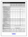
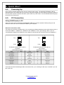
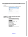
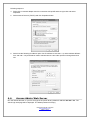
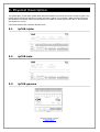
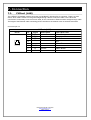
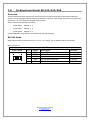
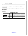
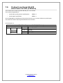
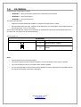
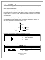
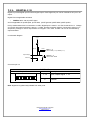
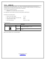
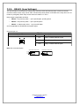
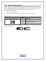
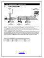
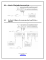
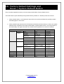
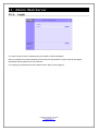
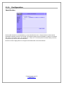
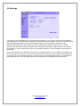
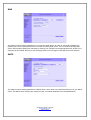
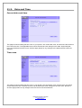
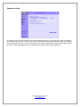
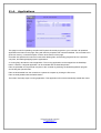
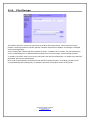
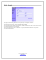
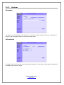
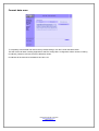
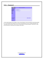
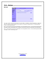
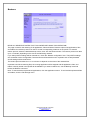
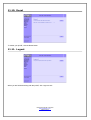
User Manual
ipCUE Controllers
Version 04
Valid for XPL2 Firmware 4.0 and higher
CUE, a.s., K Nouzovu 6, 143 00 Praha 4, Czech Republic
phone: +420 241 091 240
fax: +420 241 432 446
www.cuesystem.com
mail: [email protected]
User Manual ipCUE Controllers
UM028_04, 1.10.2010
Copyright © CUE, a.s., Praha, Czech Republic 1990 - 2010
All rights reserved. Specifications are subject to change without prior notice.
1. Introduction......................................................................................................................................... 5
1.1. Overview...................................................................................................................................................... 5
1.2. Models and Accessories.............................................................................................................................. 5
1.3. Features....................................................................................................................................................... 5
1.4. Programming................................................................................................................................................ 5
2. Box Contents...................................................................................................................................... 6
3. Specifications..................................................................................................................................... 7
4. Quick Start.......................................................................................................................................... 8
4.1. Powering Up................................................................................................................................................. 8
4.2. PC Connection............................................................................................................................................. 8
4.3. Windows Local Area Connection Settings................................................................................................... 10
4.4. Access Admin Web Server.......................................................................................................................... 11
5. Physical Description.......................................................................................................................... 12
5.1. ipCUE-alpha................................................................................................................................................. 12
5.2. ipCUE-beta................................................................................................................................................... 12
5.3. ipCUE-gamma.............................................................................................................................................. 12
5.4. ipCUE-delta.................................................................................................................................................. 13
5.5. ipCUE-epsilon.............................................................................................................................................. 13
5.6. ipCUE-sigma................................................................................................................................................ 13
6. Front Panel.......................................................................................................................................... 14
6.1. PWR Indicator.............................................................................................................................................. 14
6.2. LINK Indicator.............................................................................................................................................. 14
6.3. ACT Indicator............................................................................................................................................... 14
6.4. CPU Indicator............................................................................................................................................... 14
6.5. IR SENSOR................................................................................................................................................. 14
6.6. IR LEVEL and IR CAPTURE SENSOR....................................................................................................... 14
6.7. SERIAL Port Indicator.................................................................................................................................. 15
6.8. IR/SERIAL Output Indicator......................................................................................................................... 15
6.9. GENERAL I/O Indicator............................................................................................................................... 15
6.10. DIGITAL I/O Indicator................................................................................................................................. 15
6.11. ANALOG Output Indicator.......................................................................................................................... 15
6.12. AUX Indicator............................................................................................................................................. 15
6.13. RELAY Indicator......................................................................................................................................... 15
6.14. OUT 5 V..................................................................................................................................................... 15
6.15. OUT 12 V................................................................................................................................................... 15
7. Connection.......................................................................................................................................... 16
7.1. CUEnet (LAN).............................................................................................................................................. 16
7.2. PWR IN........................................................................................................................................................ 17
7.3. OUT 5 V....................................................................................................................................................... 17
7.4. OUT 12 V..................................................................................................................................................... 17
7.5. Bi-directional Serial RS-232......................................................................................................................... 18
7.6. Bi-directional Serial RS-232/422/485........................................................................................................... 19
7.7. Bi-directional Serial RS-232/422/485
with Power 24 VDC............................................................................................................................................. 21
7.8. Bi-directional Serial RS-485
with Power 24 VDC (CUEwire)........................................................................................................................... 23
7.9. IR/SERIAL.................................................................................................................................................... 24
7.10. GENERAL I/O............................................................................................................................................ 25
7.11. DIGITAL I/O............................................................................................................................................... 26
7.12. ANALOG.................................................................................................................................................... 27
7.13. RELAY (Low Voltage)................................................................................................................................ 28
7.14. RELAY (High Voltage)............................................................................................................................... 29
8. CUEwire Device Connection.............................................................................................................. 30
8.1. CUEwire Installation..................................................................................................................................... 30
8.2. Simple CUEwire device connection............................................................................................................. 31
8.3. Multiple CUEwire device connected to a CUEwire Splitter.......................................................................... 31
9. Mounting............................................................................................................................................. 32
9.1. Shelf Placement or Stacking........................................................................................................................ 32
9.2. Rack Mounting............................................................................................................................................. 33
9.3. DIN Rail Mounting........................................................................................................................................ 34
User Manual ipCUE Controllers
www.cuesystem.com
Page 3 of 52
10. Factory Default Settings and
Reset / System Default Button.............................................................................................................. 35
11. Admin Web Server............................................................................................................................ 36
11.1. Login.......................................................................................................................................................... 36
11.2. Configuration.............................................................................................................................................. 37
11.3. Date and Time............................................................................................................................................ 40
11.4. Applications................................................................................................................................................ 42
11.5. File Storage................................................................................................................................................ 43
11.6. E-mail......................................................................................................................................................... 44
11.7. System....................................................................................................................................................... 45
11.8. Password................................................................................................................................................... 47
11.9. Backup....................................................................................................................................................... 48
11.10. Reset........................................................................................................................................................ 50
11.11. Logout...................................................................................................................................................... 50
11.12. License..................................................................................................................................................... 51
12. Notes................................................................................................................................................. 52
User Manual ipCUE Controllers
www.cuesystem.com
Page 4 of 52
1. Introduction
1.1.
Overview
The ipCUE are Ethernet IP enabled controllers. These controllers are well suited for single-room applications
as well as huge multi-room, multi-floor distributed control applications. The ipCUE controllers come with
multiple control ports well suited for home applications as well as commercial. The control ports include bidirectional serial ports RS-232, bi-directional serial ports configurable as RS-232, RS-422, or RS-485, infrared
outputs up to 1.2 MHz that can be configured to control up to three pieces of equipment, general I/O ports that
can also be configured as analog inputs, digital I/O ports, 24 volts relays and 230 volts relays. The Ethernet
port allows for bi-directional IP control of any manufacturer IP enabled products. The ipCUE controllers are
compatible with CUE‘s existing range of touch panels, button panels and interfaces. Some controllers are
equipped with +5 VDC and/or +12 VDC output added to the design for powering external low-voltage
equipment. The units are equipped with internal IR sensor (except ipCUE-gamma). The sensor allows to
capture IR codes and links IR wireless control panels. Convenient for testing and troubleshooting all controllers
also come with indicator LEDs on the front panel, which indicates the status of all of the control ports. The
ipCUE controllers keep actual time with its built-in real time clock (RTC), thus allowing for a wide variety of
distributed intelligence scheduling applications. The ipCUE controllers come complete with a web-server and
allow for setup and configuration through a standard web browser.
1.2.
Models and Accessories
Model
ipCUE-alpha
ipCUE-beta
ipCUE-gamma
ipCUE-delta
ipCUE-epsilon
ipCUE-sigma
ipCUE Rack Mounting Kit
1.3.
Product code
CS0251
CS0252
CS0253
CS0267
CS0268
CS0333
CS0251-MR
Description
Desktop / rack enclosure
Desktop / rack enclosure
DIN rail enclosure
Desktop / rack enclosure
Desktop / rack enclosure
DIN rail enclosure
Rack 19” mounting kit
Note
No IR receiver
Power 230 V relays
Sold separately
Features
The main features of the controllers are
• Ethernet IP enabled
• Based on the 32-bit Motorola ColdFire® processor
• Fully compatible with current CUE communication buses – CUEnet2, CUEwire and PEbus
• Standard control ports - bi-directional serial, IR/serial, general I/O, digital I/O, analog and relay ports
• Web server complete with Admin Web pages for setup
• Compatible with Cue Visual Composer programming tools
• Front panel indicators for each control port
• Unified enclosure design for desktop or DIN rail
• 19" rack installation available with accessories
1.4.
Programming
All ipCUE controllers are programmed using Cue Visual Composer programming tool.
User Manual ipCUE Controllers
www.cuesystem.com
Page 5 of 52
ipCUE-alpha
ipCUE-beta
ipCUE-gamma
ipCUE-delta
ipCUE-epsilon
ipCUE-sigma
2. Box Contents
1 set
1 set
1 set
1 set
1 set
1 set
IR Adapter /i
4
4
2
4
4
2
Ethernet cable straight-through
1
1
1
1
1
1
Ethernet cable crossed-over
1
1
1
1
1
1
CUEadapter /30W
1
1
1
1
1
1
Power Cable
1
1
1
1
1
1
CE declaration
1
1
1
1
1
1
RoHS declaration
1
1
1
1
1
1
Controller data sheet
1
1
1
1
1
1
Cue System Connector Wiring
1
1
1
1
1
1
Item
Connector Set
User Manual ipCUE Controllers
www.cuesystem.com
Page 6 of 52
System connection
Ethernet connection 10/100 BaseT
LAN, RJ-45 connector
Control ports
Bi-directional serial RS-485 with power
24 VDC, 4-pin connector 5 mm. Can
be used for powered CUEwire.
Bi-directional serial RS-232/422/485
with power 24 VDC, 7-pin connector
3.5 mm. Can be used for powered
CUEwire.
Bi-directional serial RS-232,
5-pin connector 3.5 mm
Bi-directional serial RS-232/422/485,
5-pin connector 3.5 mm
IR/serial output, IR output up to 1.2
MHz, 2-pin connector 3.5 mm
General I/O input (analog 0 - 5 V,
10-bit ADC) or output (open collector
max. 24 V / 80 mA), connector 3.5 mm
General I/O input (analog 0 - 20 V,
10-bit ADC) or output (open collector
max. 24 V / 80 mA), connector 3.5 mm
Digital I/O input (contact closure / TTL,
max. 24 V, threshold 2 V) or output
(TTL / open collector max. 24 V / 80
mA), connector 3.5 mm
Analog output 0 – 10 V,
2-pin connector 3.5 mm
Relay 24 V / 0.5 A,
3-pin connector 3.5 mm
Relay 230 V / 10 A, NC-C-NO,
3 terminals 1.5 mm2
Power outputs
5 VDC (max. 1 A),
2-pin connector 3.5 mm
12 VDC (max. 800 mA),
2-pin connector 3.5 mm
Internal IR sensor for IR code capture
Internal IR sensor for IR wireless control
panel link
LED indicators
Button Reset / System default
Real time and date - RTC with battery
backup
Memory
Software
Power supply, 2-pin connector 5 mm
Power consumption
Enclosure
Dimensions (WxHxD) in mm
Weight
ipCUE-sigma
ipCUE-epsilon
ipCUE-delta
ipCUE-gamma
ipCUE-beta
Feature
ipCUE-alpha
3. Specifications
1
1
1
1
1
1
(Serial 7)
(Serial 3)
(Serial 3)
(Serial 7)
(Serial 3)
-
-
-
-
-
2
2
2
2
2
-
4
-
-
4
-
3
8
8
2
8
8
3
8
-
8
8
8
-
-
-
-
-
-
8
-
-
-
-
-
12
-
-
-
4
4
-
2
-
2
16
8
-
-
-
-
-
-
8
1
1
-
1
1
1
-
-
-
-
-
1
1
1
-
1
1
1
1
1
-
1
1
-
-
1
(Serial 1)
PWR, LINK, ACT, CPU, All control ports
1
1
12 W
Metal
Desktop
Internal RAM 16 MB, Flash 16 MB
XPL2 Runtime, Admin web
24 VDC (+/-20%)
10 W
10 W
18 W
15 W
Metal
Plastic
Metal
Metal
Desktop
DIN rail
Desktop
Desktop
210 x 43.5 x 92
210 x 43.5 x 92
0.6 kg
0.5 kg
106 x 90 x 58
6 DIN modules
0.4 kg
User Manual ipCUE Controllers
www.cuesystem.com
Page 7 of 52
422 x 43.5 x 92
210 x 43.5 x 92
0.9 kg
0.6 kg
24 W
Plastic
DIN rail
210 x 90 x 58
12 DIN modules
0.6 kg
4. Quick Start
4.1.
Powering Up
Every ipCUE controller requires power from an external power supply. The standard CUEadapter /30W is
delivered with the unit. Attach the 2-pin connector of the power supply unit to the PWR IN connector located on
the rear panel of ipCUE controller and attach power cable to a power outlet. The LED labeled PWR will light up
when the unit is powered on.
4.2.
PC Connection
Using LAN Directly to PC
Attach one end of an RJ-45 Ethernet crossed-over cable to the ipCUE controller CUEnet (LAN) port and
attach the other end of the RJ-45 Ethernet cable to your computer.
Ethernet Crossed-Over Cable
This cable can be used to cascade hubs, or for connecting two Ethernet stations back-to-back without a hub. It
works with 10Base-T, 100Base-TX, 100Base-T4 and 1000Base-T. Use a good enough cable, if you are
confused about categories of cables then use Category 5 (enhanced) and you'll be fine even at 1000Base-T.
1
8
Top
Top
Front
Front
1
8
To Network Interface Card 1 (NIC 1)
Computer
RJ45 Male Connector
1
8
1
8
To Network Interface Card 2 (NIC 2)
Touch panel
RJ45 Male Connector
Name
NIC 1
Color
NIC 2
Name
TX+ (BI_DA+)
1
White/Orange
3
RX+ (BI_DB+)
TX- (BI_DA-)
2
Orange
6
RX- (BI_DB-)
RX+ (BI_DB+)
3
White/Green
1
TX+ (BI_DA+)
- (BI_DC+)
4
Blue
7
- (BI_DD+)
- (BI_DC-)
5
White/Blue
8
- (BI_DD-)
RX- (BI_DB-)
6
Green
2
TX- (BI_DA-)
- (BI_DD+)
7
White/Brown
4
- (BI_DC+)
- (BI_DD-)
8
Brown
5
- (BI_DC-)
That means that the White/Orange cable connected to NIC 1 pin 1 should go to NIC 2 pin 3 and NIC 1 pin 2 to
NIC 2 pin 6 etc.
User Manual ipCUE Controllers
www.cuesystem.com
Page 8 of 52
Notes
1. 1000Base-T names are in parentheses.
2. It's important that each pair is kept as a pair. TX+ & TX- must be in the pair and RX+ & RX- must
together in another pair. Just as the table above shows.
3. While 10Base-T and 100Base-TX only uses 2 pairs, please connect all four since 100Base-T4 and
1000Base-T needs them and save you some future debugging.
4. The colors originate from the numbering and name on NIC 1.
5. The connection is based on IEEE Standard 802.3, 2000 Edition.
Using LAN Network
Attach one end of an RJ-45 Ethernet straight-through cable to the ipCUE controller CUEnet (LAN) port and
attach the other end of the RJ-45 Ethernet cable to your computer.
User Manual ipCUE Controllers
www.cuesystem.com
Page 9 of 52
4.3.
Windows Local Area Connection Settings
For Windows 7 steps are
1. Start Windows 7.
2. Click Start.
3. Enter ncpa.cpl to the Search Box and press Enter. Following window is displayed.
For Windows XP steps are
1. Start Windows XP.
2. Click Start, then click Control Panel choose the option to switch to Classic View.
3. Double-click Network Connections.
User Manual ipCUE Controllers
www.cuesystem.com
Page 10 of 52
Following steps are
4. Right-click on network adapter used for connection with ipCUE and then right-click and select
Properties.
5. Select Internet Protocol (TCP/IP) and click Properties button.
6. Select Use the following IP address option. Set IP address to 192.168.1.1 (or other address different
from 192.168.1.127) and Subnet mask to 255.255.255.0. Leave other options unchanged and click
OK.
4.4.
Access Admin Web Server
Run the Internet browser on your PC and type in the ipCUE factory default IP address 192.168.1.127. The
Admin login web page will be displayed. The default password is empty.
User Manual ipCUE Controllers
www.cuesystem.com
Page 11 of 52
5. Physical Description
The ipCUE-alpha, ipCUE-beta, ipCUE-delta and ipCUE-epsilon front panels are made of aluminum plate. The
ipCUE-gamma and ipCUE-sigma front panels are made of plastic. The indication LEDs and infrared sensors
are behind the front panel. Connectors and button are located on the rear panel of the device. All connectors
are labeled incl. pin out.
It should be cleaned with a soft/non-abrasive cloth.
5.1.
ipCUE-alpha
5.2.
ipCUE-beta
5.3.
ipCUE-gamma
User Manual ipCUE Controllers
www.cuesystem.com
Page 12 of 52
5.4.
ipCUE-delta
5.5.
ipCUE-epsilon
5.6.
ipCUE-sigma
User Manual ipCUE Controllers
www.cuesystem.com
Page 13 of 52
6. Front Panel
6.1.
PWR Indicator
Off.............................................No power presented.
Blue On.....................................Power 24 V is presented. The unit is ready.
6.2.
LINK Indicator
Off.............................................Network is not detected.
Green On..................................Network detected.
6.3.
ACT Indicator
Off.............................................No data transmitted or received through the CUEnet (LAN) port.
Yellow On or Flashing..............Data is being transmitted or received through the CUEnet (LAN) port.
6.4.
CPU Indicator
This Green LED indicates the end of the operating system boot up by flashing OK in Morse code. Operating
system is booted after the unit has either been reset or switched on. The booting time is approx. 15 seconds.
6.5.
IR SENSOR
The window marked by IR SENSOR (not applied in ipCUE-gamma and ipCUE-sigma), covers two IR sensors
and one LED indication.
1. The built-in IR sensor carries the same functionality as irCUE Receiver or irCUE Receiver 485. This
means that ipCUE can receive IR signal from CUE wireless IR control panels without the need to use
any external IR receiver.
2. The second built-in IR sensor allows IR codes capture directly by ipCUE unit. The flashing Yellow LED
indicates the received infra-red signal and serves for optimum distance setup between the receiver and
captured IR remoter. The flashing Red LED indicates that received infra-red signal is too strong and
capturing sensor is overloaded. In this case increase the distance between controller and transmitter.
6.6.
IR LEVEL and IR CAPTURE SENSOR
IR CAPTURE SENSOR (applied in ipCUE-sigma only) allows IR codes capture directly by ipCUE-sigma. The
flashing Yellow LED labeled IR LEVEL indicates the received infra-red signal and serves for optimum distance
setup between the receiver and captured IR remoter. The flashing Red LED indicates that received infra-red
signal is too strong and capturing sensor is overloaded. In this case increase the distance between controller
and transmitter.
User Manual ipCUE Controllers
www.cuesystem.com
Page 14 of 52
6.7.
SERIAL Port Indicator
Off.............................................No data transmitted or received through the serial port.
Green On or Flashing...............Data is being transmitted through the serial port.
Red On or Flashing...................Data is being received through the serial port.
6.8.
IR/SERIAL Output Indicator
Off.............................................No data or IR code transmitted through the IR/serial port.
Yellow On or Flashing..............Data or IR code is being transmitted through the IR/serial port.
6.9.
GENERAL I/O Indicator
Off.............................................Output is switched OFF.
Green On..................................Output is switched ON.
6.10.
DIGITAL I/O Indicator
Off.............................................Output is switched OFF.
Green On..................................Output is switched ON.
6.11.
ANALOG Output Indicator
Off.............................................Analog output is set to 0 V.
Yellow On.................................Analog output is set to 10 V.
6.12.
AUX Indicator
Off.............................................AUX (relay) is switched OFF.
Red On......................................AUX (relay) is switched ON.
6.13.
RELAY Indicator
Off.............................................RELAY is switched OFF.
Red On......................................RELAY is switched ON.
6.14.
OUT 5 V
Off.............................................Output voltage isn't presented (short circuit, overload, ...).
Green On..................................Output voltage is OK.
6.15.
OUT 12 V
Off.............................................Output voltage isn't presented (short circuit, overload, ...).
Green On..................................Output voltage is OK.
User Manual ipCUE Controllers
www.cuesystem.com
Page 15 of 52
7. Connection
7.1.
CUEnet (LAN)
The CUEnet is a standard network connection 10/100 BaseT LAN using RJ-45 connector. There is no auto
sense, which means it does not recognize straight through cable to cross-over cable. For the direct PC
connection it is necessary to use cross-over cable; for the connection to Ethernet switch straight through cable.
The length of the Ethernet cable connecting ipCUE controller to the network must not exceed 100 meters.
Connector pin out
RJ-45
8
1
Pin
1
2
3
4
5
6
7
8
CUEnet (LAN )
Signal
Description
TX_D1+
TX_D1RX_D2+
RX-D2G
G
Ground
Ground
User Manual ipCUE Controllers
www.cuesystem.com
Page 16 of 52
Cat5 Cable Color
White / Orange
Orange
White / Green
Blue
White / Blue
Green
White / Brown
Brown
7.2.
PWR IN
Warning: Use any ipCUE controller only with the power adapter supplied in the product package. Using
another power supply may damage the unit.
Connector pin out
2-pin 5 mm or 3.5 mm
+
7.3.
G
+24 G
Pin
PWR IN
Description
+24
Power +24 VDC
G
Ground
OUT 5 V
Applicable for ipCUE-alpha, ipCUE-beta, ipCUE-delta, ipCUE-epsilon, ipCUE-sigma.
Not applicable for ipCUE-gamma.
Connector pin out
2-pin 3.5 mm
+
7.4.
G
Pin
OUT 5 V
Description
+
Output +5 VDC, max. 1 A
G
Ground
OUT 12 V
Applicable for ipCUE-sigma. Not applicable for ipCUE-alpha, ipCUE-beta, ipCUE-gamma, ipCUE-delta, ipCUEepsilon.
Connector pin out
2-pin 3.5 mm
+12 G
Pin
OUT 12 V
Description
+12
Output +12 VDC, max. 800 mA
G
Ground
User Manual ipCUE Controllers
www.cuesystem.com
Page 17 of 52
7.5.
Bi-directional Serial RS-232
Applicable for ipCUE-alpha, ipCUE-beta, ipCUE-gamma, ipCUE-delta, ipCUE-epsilon as SERIAL 1 - 2. Not
applicable for ipCUE-sigma.
These two bi-directional serial channels are used for RS-232 communication. Maximum speed is 115 000 Bd
(bps). Output signal levels for RS-232 are in the -12 V to +12 V range.
Connector pin out
5-pin 3.5 mm
1 2 3 4 5
Pin
1
2
3
4
5
Signal
TxD
RTS
GND
RxD
CTS
RS-232
Description
RS-232 Transmitted Data
RS-232 Request to Send
Ground
RS-232 Received Data
RS-232 Clear to Send
User Manual ipCUE Controllers
www.cuesystem.com
Page 18 of 52
Direction
From ipCUE
From ipCUE
To ipCUE
To ipCUE
7.6.
Bi-directional Serial RS-232/422/485
Overview
These bi-directional serial channels are used for RS-232, RS-422 and RS-485 communication. Maximum
speed is 115 200 Bd (bps). Default mode for all channels is RS-232, other modes must be set in programming
application. For more details see programming manuals.
These channels are applicable as follows
•
ipCUE-alpha
SERIAL 3 - 6
•
ipCUE-delta
SERIAL 3 - 6
•
ipCUE-sigma
SERIAL 2 - 4
and not applicable for ipCUE-beta, ipCUE-gamma and ipCUE-epsilon.
RS-232 Mode
Output signal levels for RS-232 are in the -10 V to +10 V range. This is default mode for all channels.
Connector pin out
5-pin 3.5 mm
1 2 3 4 5
Pin
1
2
3
4
5
Signal
TxD
RTS
GND
RxD
CTS
RS-232
Description
RS-232 Transmitted Data
RS-232 Request to Send
Ground
RS-232 Received Data
RS-232 Clear to Send
User Manual ipCUE Controllers
www.cuesystem.com
Page 19 of 52
Direction
From ipCUE
From ipCUE
To ipCUE
To ipCUE
RS-422 Mode
This mode must be set in the programming application.
Connector pin out
5-pin 3.5 mm
1 2 3 4 5
Pin
1
2
3
4
5
Signal
Tx A+
Tx BGND
Rx A+
Rx B-
RS-422
Description
RS-422 Transmit Data (Idles High)
RS-422 Transmit Data (Idles Low )
Ground
RS-422 Receive Data (Idles High)
RS-422 Receive Data (Idles Low)
RS-485 Mode
This mode must be set in the programming application.
Connector pin out
5-pin 3.5 mm
1 2 3 4 5
Pin
1
2
3
4
5
Signal
A+
BGND
N.C.
N.C.
RS-485
Description
RS-485 Data +
RS-485 Data Ground
Not Connected
Not Connected
User Manual ipCUE Controllers
www.cuesystem.com
Page 20 of 52
Direction
From ipCUE
From ipCUE
To ipCUE
To ipCUE
7.7.
Bi-directional Serial RS-232/422/485
with Power 24 VDC
Overview
This bi-directional serial channel is used for RS-232, RS-422 and RS-485 communication and for power supply
24 VDC and it is applicable for ipCUE sigma SERIAL 1. Maximum speed is 115 200 Bd (bps). Default mode for
all channels is RS-232, other modes must be set in programming application. For more details see
programming manuals.
This channel is not applicable for ipCUE-alpha, ipCUE-beta, ipCUE-gamma, ipCUE-delta, ipCUE-epsilon.
RS-232 Mode
Output signal levels for RS-232 are in the -10 V to +10 V range. This is default mode.
Connector pin out
7-pin 3.5 mm
+24 G
1
2
3
4
5
Pin
+24
G
1
2
3
4
5
RS-232 with power 24VDC
Signal
Description
+24
Power +24VDV
GND
Ground
\
TxD
RS-232 Transmitted Data
RTS
RS-232 Request to Send
GND
Ground
RxD
RS-232 Received Data
CTS
RS-232 Clear to Send
User Manual ipCUE Controllers
www.cuesystem.com
Page 21 of 52
Note
From ipCUE
From ipCUE
To ipCUE
To ipCUE
RS-422 Mode
This mode must be set in the programming application.
Connector pin out
7-pin 3.5 mm
+24 G
1
2
3
4
5
Pin
+24
G
1
2
3
4
5
RS-422 with power 24VDC
Signal
Description
+24
Power +24VDV
GND
Ground
Tx A+
RS-422 Transmit Data (Idles High)
Tx BRS-422 Transmit Data (Idles Low )
GND
Ground
Rx A+
RS-422 Receive Data (Idles High)
Rx BRS-422 Receive Data (Idles Low)
Note
From ipCUE
From ipCUE
To ipCUE
To ipCUE
RS-485 Mode (CUEwire)
This mode is suitable for connection of CUEwire devices and it must be set in the programming application.
This mode can be also used for general RS-485 communication.
Connector pin out
7-pin 3.5 mm
+24 G
1
CUEwire
2
3
4
5
RS-485 with power 24VDC (CUEwire)
Pin
Signal
Description
+24
+24
Power +24VDV
G
GND
Ground
1
A+
RS-485 Data +
2
BRS-485 Data 3
GND
Ground
4
N.C.
Not Connected
5
N.C.
Not Connected
User Manual ipCUE Controllers
www.cuesystem.com
Page 22 of 52
Note
CUEwire
CUEwire
CUEwire
CUEwire
7.8.
Bi-directional Serial RS-485
with Power 24 VDC (CUEwire)
This channel can be used as general RS-485 port or as CUEwire.
This channel is applicable for
•
ipCUE-beta, ipCUE-gamma, ipCUE-epsilon
SERIAL 3
•
ipCUE-alpha, ipCUE-delta
SERIAL 7
and not applicable for ipCUE-sigma. See previous section how to connect CUEwire to ipCUE-sigma.
This mode can be also used for general RS-485 communication.
Connector pin out
4-pin 5 mm
+24 G A+ B-
RS-485 with power 24 VDC (CUEwire)
Pin
Description
+24
Power +24 VDC
G
Ground
A+
RS-485 Data +
BRS-485 Data -
User Manual ipCUE Controllers
www.cuesystem.com
Page 23 of 52
7.9.
IR/SERIAL
IR/Serial output is applicable as follows
•
IR/SERIAL 1 – 8 on ipCUE-alpha, ipCUE-beta, ipCUE-delta, ipCUE-epsilon
•
IR/SERIAL 1 – 3 on ipCUE-sigma
•
IR/SERIAL 1 – 2 on ipCUE-gamma.
This type of port provides
•
Output for infra-red emitters (IR Adapter /i), maximum IR output rate is 1.2 MHz.
•
RS-232 serial output (one way), maximum serial data rate is 115 200 Bd (bps), output signal levels for
RS-232 are in the -12 V to +12 V range.
The IR outputs and RS-232 outputs can be combined on independent outputs (for example three outputs can
be used as IR, five outputs can be used as RS-232).
Connector pin out
2-pin 3.5 mm
IR/SERIAL
Pin
Description
S G
S
IR/Serial Signal (Output)
G
Ground
Notes
•
All pins labeled G are connected together.
•
Up to three original infra-red emitters IR Adapter /i can be connected to each output in parallel.
•
Up to ten IR Sprayers can be connected to each output in parallel
•
It is not recommended to connect more infra-red emitters of various manufacturers in parallel because
the output can be either overloaded or damaged.
User Manual ipCUE Controllers
www.cuesystem.com
Page 24 of 52
7.10.
GENERAL I/O
General I/O provide analog input as well as digital output. Each General I/O port can be used either as input or
as output.
General I/Os are applicable as follows
•
GENERAL I/O 1 - 8 on ipCUE-alpha, ipCUE-gamma, ipCUE-delta, ipCUE-epsilon, ipCUE-sigma
and not applicable for ipCUE-beta.
Pull-up resistor 680 ohms is connected to +5 VDC and can be switched on and off for each I/O independently.
I/O voltage with pull-up on is approx. +4.3 VDC, because protection diode is connected in series (0.7 V dropdown).
Analog input is rated
•
0 – 5 VDC for ipCUE-alpha, ipCUE-gamma, ipCUE-delta, ipCUE-epsilon
•
0 – 20 VDC for ipCUE-sigma.
Analog to digital (A/D) converter has 10-bits precision (i.e. 1024 levels). Digital output can switch max. 24
VDC / 80 mA. Output voltage for output switch on is approx. 0.6 V.
IO schematic diagram
GENERAL I/O on ipCUE controller
+5 VDC
ON
OFF
PULLUP 1 – 8
value ON / OFF
A
INPUT 1 – 8
680 Ohm
D
10 bit
Input / Output
OUTPUT 1 – 8
value CLOSE / OPEN
Ground
Connector pin out for ipCUE-alpha, ipCUE-gamma, ipCUE-delta, ipCUE-epsilon
2-pin 3.5 mm
GENERAL I /O
Pin
Description
S G
S
Input / Output Signal
G
Ground
Note: All pins labeled G are connected together.
Connector pin out for ipCUE-sigma
9-pin 3.5 mm
GENERAL I /O
Pin
Description
1-8
1 2 3 4 5 6 7 8 G
G
Input / Output Signal 1 - 8
Ground
User Manual ipCUE Controllers
www.cuesystem.com
Page 25 of 52
7.11.
DIGITAL I/O
Digital I/O provide digital input as well as digital output. Each Digital I/O port can be used either as input or as
output.
Digital I/Os are applicable as follows
•
DIGITAL I/O 1 - 12 on ipCUE-sigma
and not applicable for ipCUE-alpha, ipCUE-beta, ipCUE-gamma, ipCUE-delta, ipCUE-epsilon.
Pull-up resistor 680 ohms is connected to +5 VDC. Digital input is rated 0 – 24 VDC, threshold is 2 V. Voltage
on I/O with open output transistor is approx. 4.3 VDC, because protection diode is connected in series (0.7 V
drop-down). Voltage on I/O for output switch on is approx. 0.6 V. Max. 24 VDC / 80 mA can be switched by
output transistor.
IO schematic diagram
DIGITAL I/O on ipCUE controller
+5 VDC
680 Ohm
10 kOhm
Input / Output
INPUT 1 – 8
value CLOSE (< 2 V) / OPEN (> 2 V)
OUTPUT 1 – 8
value CLOSE / OPEN
Common
Connector pin out
13-pin 3.5 mm
DIGITAL I/O
Pin
Description
1 - 12
1 2 3 4 5 6 7 8 9 10 11 12 C
C
Input / Output Signal 1 - 12
Common
Note: Digital I/O is galvanically isolated from other ports.
User Manual ipCUE Controllers
www.cuesystem.com
Page 26 of 52
7.12.
ANALOG
Analog output provides analog output 0 - 10 V. When connecting with another device (e.g. dimmer) it is
essential to see to a perfect interconnection with earth. The output voltages generated by the analog output is
mutually related to the reference level (ground) on pin labeled G.
Analog output is applicable as follows
•
ANALOG 1 - 4 for ipCUE-delta and ipCUE-epsilon.
Nor applicable for ipCUE-alpha, ipCUE-beta, ipCUE-gamma, ipCUE-sigma.
Parameters of the analog output
•
Range of the output voltage
0 - 10 V
•
Max. output current (both source and sink)
10 mA
•
Stepping regulation (LSB)
39 mV
•
Min. set-up precision
± 0.08 V (± 2 LSB)
Connector pin out
2-pin 3.5 mm
S
G
Pin
ANALOG
Description
S
Analog Output Signal 0 – 10 V
G
Ground
Note: All pins labeled G are connected together.
User Manual ipCUE Controllers
www.cuesystem.com
Page 27 of 52
7.13.
RELAY (Low Voltage)
This port provides one isolated low voltage relay. Normally Close and Normally Open contacts as well as
Common contact of each relay can be used. The Normally Close position is the state of the relay when it is not
turned on (energized). Each relay contact closure is rated 24 V / 0.5 A.
Relay output is applicable as follows
•
RELAY 1 – 2 (formerly AUX 1 - 2) for ipCUE-alpha, ipCUE-gamma
•
RELAY 1 – 8 (formerly AUX 1 - 8) for ipCUE-epsilon
•
RELAY 1 – 16 (formerly AUX 1 - 16) for ipCUE-delta
and not applicable for ipCUE-beta and ipCUE-sigma.
Connector pin out
RELAY
Pin
3-pin 3.5 mm
NC
C
NC C NO
NO
Description
Relay Contact Normal Close
Relay Contact Common
Relay Contact Normal Open
Note: NC-C-NO description
Open RELAY inside ipCUE
Close RELAY inside ipCUE
NC
C
NO
User Manual ipCUE Controllers
www.cuesystem.com
Page 28 of 52
7.14.
RELAY (High Voltage)
This port provides one isolated high voltage relay. Normally Close and Normally Open contacts as well as
Common contact of each relay can be used. The Normally Close position is the state of the relay when it is not
turned on (energized). Each relay contact closure is rated max. 230 V, max. 10 A for resistive loads. Max. 400
W per relay can be switched for inductive or capacitive loads. Terminals 1.5 mm2 are used.
Relay output is applicable as follows
•
RELAY 1 – 8 for ipCUE-sigma
and not applicable for ipCUE-alpha, ipCUE-beta, ipCUE-gamma, ipCUE-delta, ipCUE-epsilon.
Connector pin out
3-pin screw -type terminals
RELAY
Pin
NC
C
NC
C
NO
NO
Description
Relay Contact Normal Close
Relay Contact Common
Relay Contact Normal Open
Note: NC-C-NO description
Open RELAY inside ipCUE
Close RELAY inside ipCUE
NC
C
NO
User Manual ipCUE Controllers
www.cuesystem.com
Page 29 of 52
8. CUEwire Device Connection
8.1.
CUEwire Installation
On the picture you can see a typical connection of CUEwire.
Controller
CUEwire 4-pin Connector
(3.5 or 5 mm type)
GND
+ 24 VDC
External power
supply
+ 24 VDC
GND
120 ohm
A+
B-
4-pin
4-pin
CUEwire Device N
CUEwire Device 2
4-pin
CUEwire Device 1
The cable consists of 4 wires. The first pair serves as a signal line. The second pair of wires serves for power
distribution. The signal conductors can have minimum 0.25 mm2, maximum capacity 100 pF/m.
The power distribution cable design depends on how many CUEwire devices are connected and on the
required length of the cable. The maximum voltage loss on the whole power distribution conductors should not
exceed 4 V on the ground wire and 4 V on the +24 V wire.
To supply power distribution line of the Bi-directional Serial RS-485 with Power 24 VDC (CUEwire) port on the
controller can be used. In this case the whole consumption should not exceed 2 A. In case of exceeding 2 A
consumption or for longer distances it is necessary to use external power supply +24 V for remote CUEwire
devices (see example of the Device N in the picture “Multiple CUEwire device connected to a CUEwire
Splitter” below).
Table of maximum cable lengths are
Consumption
10 W
20 W
30 W
Cable 1 mm2
200 m
100 m
60 m
Cable 2 mm2
400 m
200 m
130 m
User Manual ipCUE Controllers
www.cuesystem.com
Page 30 of 52
8.2.
Simple CUEwire device connection
8.3.
Multiple CUEwire device connected to a CUEwire
Splitter
User Manual ipCUE Controllers
www.cuesystem.com
Page 31 of 52
9. Mounting
9.1.
Shelf Placement or Stacking
Applicable for ipCUE-alpha, ipCUE-beta, ipCUE-delta, ipCUE-epsilon and not applicable for ipCUE-gamma
and ipCUE-sigma.
Rubber feet are provided for shelf placement or stacking. Stick the feet near the corner edges on the bottom
side of the ipCUE Controller.
Four Rubber Feet
User Manual ipCUE Controllers
www.cuesystem.com
Page 32 of 52
9.2.
Rack Mounting
Applicable for ipCUE-alpha, ipCUE-beta, ipCUE-delta, ipCUE-epsilon and not applicable for ipCUE-gamma
and ipCUE-sigma.
The ipCUE Rack Mounting Kit (CS0251-MR) provides simple solution for installing ipCUE controllers the 19”
rack. It allows install two half-rack sized controllers (ipCUEs (ipCUE-alpha, ipCUE-beta, ipCUE-epsilon) or one
controller ipCUE-delta to single 19” unit rack space. All necessary accessories are supplied with the kit.
Controller is fixed to the ipCUE Rack Mounting Kit by two screws M3x6 using threads on the bottom side of
ipCUE. See picture below. Screws M3x6 are bundled to ipCUE Rack Mounting Kit. Don't use longer screws to
avoid damage of PCBs inside controller.
Threads M3 for mounting on ipCUE Rack Mounting Kit
User Manual ipCUE Controllers
www.cuesystem.com
Page 33 of 52
9.3.
DIN Rail Mounting
Applicable for ipCUE-gamma and ipCUE-sigma, not applicable for ipCUE-alpha, ipCUE-beta, ipCUE-delta,
ipCUE-epsilon.
ipCUE-gamma and ipCUE-sigma are ready to be installed to standard DIN Rail without additional hardware.
ipCUE-gamma occupies 6 DIN modules (106 mm) and ipCUE-sigma occupies 12 DIN modules (210 mm).
User Manual ipCUE Controllers
www.cuesystem.com
Page 34 of 52
10. Factory Default Settings and
Reset / System Default Button
Every controller shipped from factory is set according to table bellow, Factory Default column.
The button Reset / System Default (formerly labeled Factory Default or F. Default) carries two functions
1. When pressed shortly (< 2 seconds) the reset of the unit is performed followed by operating system
boot taking approx. 15 seconds.
2. When pressed longer (until the CPU LED indicator will flash three times shortly to confirm), the system
default function is performed according to table bellow, System Default column. The main purpose of
this functionality is to regain connection to controller with lost password or unknown IP settings.
Factory Default
System Default
Identification
Name
Empty
Not changed
IP settings
Host name
Empty
Not changed
IP address
192.168.1.127
192.168.1.127
Subnet mask
255.255.255.0
255.255.255.0
Default gateway
192.168.1.1
192.168.1.1
Primary DNS server
Empty
Not changed
Secondary DNS server
Empty
Not changed
Day, month, year
Real
Not changed
Hour, minute, second
Real
Not changed
Time zone
(GMT+1:00 CET/CEST
Belgrade, ..., Prague)
Not changed
Use Internet clock
Not
Not changed
Primary NTP server
Empty
Not changed
Secondary NTP server
Empty
Not changed
Applications
Empty
Not changed
File storage
Empty
Not changed
Current version
Not changed
Empty
Empty
Configuration
DNS
Date and time
Date and Time
Internet clock
System
Password
Firmware
User Manual ipCUE Controllers
www.cuesystem.com
Page 35 of 52
11. Admin Web Server
11.1.
Login
You have to login at first for operating with your ipCUE via these web pages.
Enter your password into the Password box and click the Login button to enter the ipCUE web pages.
Remember that the password is case sensitive.
For changing your password use the Password menu after you are logged in.
User Manual ipCUE Controllers
www.cuesystem.com
Page 36 of 52
11.2.
Configuration
Identification
Each ipCUE controller can be identified by a unique identification name. Unique names are most useful in
applications requiring more than one ipCUE. This enables programmers and installers to reference controllers
with logical, user friendly names, like “boardroom,” “lobby,” etc. To set the ipCUE controller identity, enter the
unique name you wish to use in the Name box.
Be sure to click the Apply button for changes to the identification to become effective!
User Manual ipCUE Controllers
www.cuesystem.com
Page 37 of 52
IP Settings
This page is used for establishing the communication parameters for your ipCUE. The ipCUE uses standard
internet protocol (IP) communication parameters. Certain parameters can be reset by the user. On start up, this
page will display the ipCUE’s given Physical address (MAC), Current IP address. Carefully note this
addressing information (and any changes you elect to make to the IP address, subnet mask, or default
gateway). This information must be entered into the CUE System Director® program written for your specific
application. For control systems with more than one ipCUE controllers, a unique IP address must be given to
each ipCUE.
Some control systems are “stand alone” and not part of a larger network. For such “stand alone” systems, the
Host name is optional. However, for control systems that are connected to a larger network, please obtain the
Host name from the network administrator, and enter it into the corresponding box. DHCP is not supported in
this release. Be sure to click the Apply button for any changes to the IP settings to become effective!
User Manual ipCUE Controllers
www.cuesystem.com
Page 38 of 52
DNS
This page is used for setting parameters of your ipCUE’s DNS server. On start up, this page will display the
ipCUE’s given Current primary DNS server, Current secondary DNS server. You can reset the primary DNS
server and secondary DNS server manually by entering your changes into the appropriate boxes. DHCP is not
supported in this release. Be sure to click the Apply button for any changes to the DNS to become effective!
SMTP
This page is used for setting parameters of SMTP server. Set a name or an address and the port of your SMTP
server. The SMTP server and port are used by the XPL commands EmailSend and PresetEmailSend.
User Manual ipCUE Controllers
www.cuesystem.com
Page 39 of 52
11.3.
Date and Time
Current date and time
This page is used for setting the time clock on your ipCUE. The current date, time, and time zone are shown on
the Current time line. The applicable boxes can be selected to enter changes to the: date: day/month/year,
time: hour/minute/second. Be sure to click the Apply button for any changes to the date and time to become
effective!
Time zone
This page is used for setting the time zone on your ipCUE. The current date, time, and time zone, are shown
on the Current time line. The time zone box can be selected to enter changes to the Time zone. Be sure to
click the Apply button for any changes to the time zone to become effective!
User Manual ipCUE Controllers
www.cuesystem.com
Page 40 of 52
Internet clock
This page is used for synchronization of the ipCUE’s date and time with an internet clock. Begin by selecting
the check box for Use Internet clock. Next, enter the IP addresses (or complete address name) of the primary
and secondary NTP servers. Use the Primary NTP server and Secondary NTP server boxes for this purpose.
Be sure to click the Apply button for any changes to the internet clock to become effective!
User Manual ipCUE Controllers
www.cuesystem.com
Page 41 of 52
11.4.
Applications
This page is used for uploading compiled CUE System Director® programs to your controller. All uploaded
applications are listed on this page, along with their file properties: file name/file size/date. The controller has a
generous memory; unused free space is shown at the bottom of this page.
Controller also permits other service functions like deleting files, downloading programs back to a personal
computer, and starting/stopping specific applications.
A “running flag” denotes the active application. The running application can be stopped via the Start/Stop
button. Likewise, a stopped application can be restarted with the Start/Stop button.
Files are uploaded from a personal computer to the controller by selecting the desired application program,
and clicking the Upload button.
Files are downloaded from the controller to a personal computer by clicking the File name.
Files are easily deleted with the Delete button.
The button Total stop stops a running application. This application will not be automatically started after reset.
User Manual ipCUE Controllers
www.cuesystem.com
Page 42 of 52
11.5.
File Storage
The ipCUE’s generous memory can be used as an auxiliary file storage device. This is helpful for storing
presets, in archiving electronic manuals, pdf files, and other support documentation. File storage is managed
via the file storage page.
A list of existing files, folders, and their properties is shown. To delete a file or a folder, click the Delete button
on the corresponding line. To delete all files and folders from the current folder, click the Delete All button.
To create a new folder, enter a name for the new folder, and click the Create button. To upload a file, select the
desired file, and click the Upload button.
Note: Files are automatically compressed for the ipCUE’s internal file system. Accordingly, the size of your
uncompressed file before storing may not match the decrease of free space shown on the ipCUE.
User Manual ipCUE Controllers
www.cuesystem.com
Page 43 of 52
11.6.
E-mail
This page is used for setting parameters of email parameters and recipients addresses.
The SMTP server must be set. See the Configuration/SMTP setting.
The sender Name and E-mail are addresses of your ipCUE. The sender Name and E-mail are used by the XPL
commands EmailSend and PresetEmailSend.
The recipient Names and E-mails are addresses of recipients, where emails will be sent using the XPL
command PresetEmailSend.
User Manual ipCUE Controllers
www.cuesystem.com
Page 44 of 52
11.7.
System
Firmware
This page is used for updating the ipCUE firmware. The Current version of firmware is shown. To upload new
firmware, select the desired version, and click the Upload button.
Information
The page shows basic information about your ipCUE’s hardware. The CPU type, CPU frequency, and the flash
and RAM memory sizes are shown.
User Manual ipCUE Controllers
www.cuesystem.com
Page 45 of 52
Format data area
To completely clear all data and restore factory default settings, click the Format data area button.
This will remove all data, including Applications and File storage files. Configuration will be cleared, including
IP address, password, and touch-screen calibration values.
IP address will be restored to the default 192.168.1.127.
User Manual ipCUE Controllers
www.cuesystem.com
Page 46 of 52
11.8.
Password
A case sensitive password is necessary to login to the web pages. Set a new password via the New password
box. You must reenter the password in the Confirm new password box (an error message will appear if the
confirmation does not match, in which case you should reenter your password again in both boxes). Finally,
the new password is implemented by clicking the Apply button.
User Manual ipCUE Controllers
www.cuesystem.com
Page 47 of 52
11.9.
Backup
Backup
The page is used for the backup applications, files and folders. The Backup copies all Applications, Application
data, File storage and Web storage to the one archive. This archive is saved to the PC. To start the backup
process, click the Backup button.
Note: To see the backed-up/restored applications, click the Applications menu. To see backed-up/restored files
and folders, click the File Storage menu. The page is used for the backup of all applications, files and folders.
Note: To see the backed-up/restored applications, click the Applications menu. To see backed-up/restored files
and folders, click the File Storage menu.
User Manual ipCUE Controllers
www.cuesystem.com
Page 48 of 52
Restore
READ ALL IMPORTANT NOTES THAT FOLLOW BEFORE USING THIS OPERATION!
The page is used for the restoring of all applications, files and folders. Restore copies of all applications, files,
and folders from a backup archive on the PC to their corresponding locations on the ipCUE. To start the
restore process, select the desired backup archive, then click the Restore button. The restore process can take
up to 10 minutes, depending on the size of the files being restored.
If you want ipCUE’s settings will be restored too, check the “Restore configuration” box. The ipCUE’s settings
are accessible via the Configuration, Date and time and Password menus. Important note: actual password
and IP settings will be restored too.
The restore process takes from 1 to 10 minutes. It depends on the sizes of the restored files.
Important note: When restoring files, the running application will be stopped and all applications, files, and
folders currently stored in the ipCUE will be deleted! If you want to retain them, use the Backup command
before the Restore command.
Note: To see the backed-up/restored applications, click the Applications menu. To see backed-up/restored files
and folders, click the File Storage menu.
User Manual ipCUE Controllers
www.cuesystem.com
Page 49 of 52
11.10. Reset
To restart your ipCUE, click the Reset button.
11.11. Logout
When you are finished working with the ipCUE, click Logout to exit.
User Manual ipCUE Controllers
www.cuesystem.com
Page 50 of 52
11.12. License
User Manual ipCUE Controllers
www.cuesystem.com
Page 51 of 52
12. Notes
User Manual ipCUE Controllers
www.cuesystem.com
Page 52 of 52