1
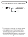
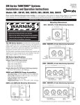
Keller America Inc
User’s Guide
Table of Contents
I.
Company Information .…………………………………………………………………………………2
II.
Contact Information ……………………………………………………………………………………..2
III.
Product Applicability …………………………………………………………………………………….2
IV.
Product Overview………………………………………………………………………………………….3
V.
Lightning/Surge Protection……………………………………………………………………………4
VI.
Options / Accessories……………………………………………………………………………………4
VII.
Use and Care…………………………………………………………………………………………………6
VIII. Installation .……………….………………………………………………………………………………..8
IX.
General Maintenance ………………………………………………………………………………….9
X.
Terms and Conditions …………………………………………………………………………………..9
XI.
Appendix……….……………………………………………………………………………………………..13
a.
Generic 2-wire Current Loop Configuration………………………………….A-1
b.
Generic 3-wire Voltage Output Configuration………………………………A-1
i.Econoline
1.
4-20 mA, Cable…………………………………………...........A-2
2.
4-20 mA, mPm Connector…………………………………..A-2
3.
0.5-4.5 VDC, Cable………………………………………………A-2
4.
0.5-4.5VDC, mPm Connector………………………………A-2
ii.
Valueline
1.
4-20 mA, Cable……………………………………………………A-3
2.
4-20 mA, DIN43650 Connector……………………………A-3
3.
4-20 mA, MIL-C-26482 Connector……………………… A-4
4.
0-5/10 VDC, Cable… ……………………………………………A-3
5.
0-5/10 VDC, DIN43650 Connector ………………………A-3
6.
0-5/10 VDC, MIL-C-26482 Connector ………………….A-4
iii.
Preciseline
1.
4-20 mA + RS485, Cable………………………………………A-5
2.
4-20 mA ONLY, DIN43650 Connector…………………..A-5
3.
4-20 mA + RS485, MIL-C-26482 Connector………….A-6
4.
0-5/10 VDC +RS485, Cable………………………………….A-5
5.
0-5/10 VDC+ RS485, DIN43650 Connector………….A-5
6.
0-5/10 VDC +RS485, MIL-C-26482 Connector .…...A-6
iv.
Levelgage
1.
4-20 mA, Cable……………………………………………………A-7
2.
0-5/10 VDC, Cable ………………………………………..……A-7
v.
Acculevel
1.
4-20 mA + RS485, Cable……………………………………..A-7
2.
0-5/10 VDC + RS485, Cable…………………………………A-7
vi.
LevelRat
1.
4-20mA, Cable………………..............………………………A-8
vii.
Microlevel / Nanolevel
1.
4-20 mA + RS485, Cable……………………………………..A-8
c.
Submersible Level Transmitters
i.
Installation Tips..………………………………………….………………A9-11
Rev. 12/15
Keller America Inc
User’s Guide
Rev. 12/15
I. Company Information
Keller America Inc is the North American subsidiary of Keller AG für Druckmesstechnik, which continues as the leader in
level and pressure sensing. From humble beginnings, Keller now provides its products and expertise through a worldwide
network of factory-trained professionals.
With the advent of inexpensive, miniaturized microprocessors, Keller continues to advance the state-of-the-art in fully
packaged pressure transmitters, with Total Error Band performance not possible just a few short years ago. Annual sensor production now exceeds 1 million pieces.
Doing business with Keller is easy and most inquiries are answered within 24 hours. Standard delivery on U.S.-assembled
products is 3 days ARO. We offer convenient terms with approved credit and accept most major credit cards.
At Keller, providing customers with superior value is a way of life.
II. Contact Information
Keller America, Inc.
351 Bell King Rd
Newport News, Virginia, 23606
P: 877-253-5537
F: 757-596-6659
Web: www.kelleramerica.com
Email: [email protected]
III. Product Applicability:
Unless otherwise noted, this manual contains user information for the following level and pressure instrumentation
provided by Keller America: Acculevel™, Levelgage™, LevelRat™ , Microlevel™, and Nanolevel™ submersible level transmitters; Econoline™, Valueline™, and Preciseline™ above ground pressure transmitters.
Electronic copies of this user’s guide can be found at:
http://www.kelleramerica.com/manuals-and-software/manuals-software-drivers.html
Page 2
Keller America Inc
User’s Guide
Rev. 12/15
IV. Product Overview:
A.
Level Transmitters
Acculevel
The Acculevel from Keller is a high accuracy submersible level transmitter. Incorporating all of
The features of the Levelgage, the Acculevel has additional features that provide enhanced functionality,
including dual outputs; i.e., one analog (4…20mA, 0…5 VDC, 0…10VDC) and one digital (RS485). The
RS485 interface provides level and temperature information. Also, it allows the user to rescale the analog output from 10…110% of the basic range. Additionally, the Acculevel is capable of greater accuracy than the Levelgage, with a standard accuracy of 0.25% FS TEB and an optional 0.1% FS TEB. The Acculevel can be
manufactured in 316L stainless steel or titanium for increased resistance to corrosion, notably from seawater.
Levelgage The Keller Levelgage is a general purpose submersible level transmitter available in 1% and 0.5% FS TEB accuracy. Constructed from 316L stainless steel, it is ideally suited for most fresh water
monitoring applications. It is available in custom ranges from 0…3 ftWC to 0…900ftWC. Cable lengths are
cut to user specifications. The Levelgage is also available in various output configurations, including 4…20mA, 0…5 VDC, and 0…10VDC.
LevelRat
The Keller LevelRat is specifically designed to provide accurate level indication in grease-laden
environments commonly found in lift stations serving commercial concerns. The LevelRat design takes a
step away from the large and bulky protection cage designs by utilizing a unique diaphragm material that
offers the non-stick properties of Teflon and provides added resistance to damage from debris.
The LevelRat is offered with various analog outputs (4…20mA, 0…5VDC, or 0…10VDC) and in level ranges
from 0…5ftWC to 0…100ftWC.
Microlevel
The Microlevel combines the capability of the Acculevel with a class leading 0.63” (16mm) outside
diameter. The Microlevel is available in full scale ranges from 0…3 ftWC through 0…900 ftWC and
is available with standard accuracy 0.25% FS TEB and 0.1% FS TEB optional. Like the Acculevel, it also provides
both 4…20mA analog and RS485 Digital output. The RS485 interface provides level and temperature information. It also allows the user to rescale the analog output from 10…110% of the basic range.
Nanolevel
The Nanolevel is uniquely designed for high accuracy measurement of very low pressure ranges.
The Nanolevel is available in full scale ranges from 0…4 inWC through 0…10 ftWC and
is available with standard accuracy 0.25% FS TEB and 0.1% FS TEB optional. Like the Acculevel, it also provides
both 4…20mA analog and RS485 Digital output. The RS485 interface provides level and temperature information. It also allows the user to rescale the analog output from 10…110% of the basic range.
Page 3
Keller America Inc
User’s Guide
Rev. 12/15
Econolevel
The Econolevel by Keller is a low cost general purpose submersible level transmitter designed for high volume
applications. It is available in nominal pressure ranges for tank and well level monitoring applications. The Econo
level provides a 4…20mA analog output that is compatible with most SCADA systems and PLCs. Minimum order quantities apply.
B.
Pressure Transmitters
Econoline
The Econoline by Keller is a low cost general purpose pressure transmitter. It is available in
nominal pressure ranges between 15psi and 10,000psi and with a threaded ¼”NPT pressure connection. Ideal
for tank and pipe pressure monitoring application, it provides either 4…20mA or 0.5…4.5VDC
(ratiometric or non-ratiometric) analog outputs that are compatible with most SCADA systems and PLCs.
Valueline
The Valueline by Keller is a highly versatile and accurate pressure transmitter. It is
available in custom pressure ranges from 0…2 through 0…15,000PSI and your choice of electrical
connections including attached cable, DIN 43650, and MIL-C-26482 connectors. The attached cable
version is fully submersible, making it the ideal choice when installed in a valve pit or other environment prone
to periodic flooding.
Preciseline
The Preciseline is our most accurate above-ground pressure transmitter. With standard
accuracy of 0.25% FS TEB and optional 0.1% FS TEB, a ¼” NPT pressure connection, and dual outputs
(analog and digital) the Preciseline offers versatility in design and application. Like the Acculevel, the
analog output can be rescaled via the RS485 interface. The RS485 interface also allows temperature data
to be retrieved if the application demands. V. Lightning / Surge Protection:
As of this writing, Keller is the only pressure/level transmitter manufacturer in the world to provide, at no
additional charge, a lifetime warranty against damage caused by lightning and/or electrical surge. This guarantee applies to the 4…20 mA output version of the following products: Levelgage, Acculevel, LevelRat, Valueline, and
Preciseline.
This warranty applies even in the case of a direct lightning strike. The user’s liability is limited to shipping costs to Keller America.
VI. Options /Accessories:
Titanium Construction -
Optional for the Acculevel only and highly recommended for brackish and sea water
applications.
Page 4
Keller America Inc
User’s Guide
Rev. 12/15
External Surge Protector -
½” NPT Pipe conduit fitting -
Recommended for lightning/surge protection of user’s power supply/readout/PLC, etc. Can be used in conjunction with Levelgage, Acculevel, LevelRat, Microlevel, Nanolevel, Valueline, or Preciseline transmitters.
Drying Tube Assembly - Clear tube filled with indicating desiccant, attaches directly to cable vent tube, intercepts
water vapor. Highly recommended when operating is in high humidity conditions. Must
be periodically renewed as desiccant becomes saturated, turning color from blue (dry) to
pink (saturated).
½” NPT male fitting, allows rigid mounting to ½” conduit for Levelgage, Acculevel, or LevelRat submersible transmitters. It can also be added to our Preciseline and Valueline
pressure transmitters.
Bellows Assembly -
Alternative to the drying tube, this aneroid bellows attaches to cable vent tube and
requires no periodic maintenance. Recommended where a slight sacrifice in accuracy
can be tolerated.
Electrical Connectors - mPm393 is optional for the Econoline, DIN43650 and MIL-C 26482 are optional for
Valueline and Preciseline. The mPm393 and MIL-C 26482 mating connectors feature
solder cups while the DIN43650 incorporates screw terminals.
RS485 Converter/Cable - For the user who wishes to communicate with their Acculevel, Nanolevel, Microlevel, or Preciseline transmitter via the RS485 digital interface. Available in RS232 and USB
versions, along with cable adapters, as needed, and Read 30/Prog 30 Software (also available for download, free of charge from www.kelleramerica.com). Consult factory for
details.
Termination Enclosure - Convenient option complementing gauge-type pressure/level transmitters, where it is
desired to terminate the transmitter cable close to the measurement point. It includes
a NEMA 4X clear front enclosure (7.9 X 4.7 X 3.5 inches) with two, liquid-tight cable
fittings (one in, one out), a terminal strip, and ample room for mounting a drying tube or
bellows assembly.
Stabilizing Weight - Zinc prop shaft anode adapted to fit Ø21 mm O.D. of Levelgage, Acculevel, and LevelRat submersible level transmitters. Aids in corrosion resistance as well as helps ensure that
the cable remains taut in turbulent conditions.
Cable Hanger - Single eye for 0.230” diameter cable. Designed to grip the cable jacket and provide a
suspension point for installation of cabled transmitters.
Pressure Test Adapters -
Designed to facilitate calibration and maintenance testing, these specialty adapters allow
for connection of the various Keller level transmitters to a pressure calibrator. Digital Display / Meter -
The TRIDENT display by Precision Digital is a verstile and cost effective process meter
providing an easy to use and read display / controller for your level and pressure
measurement application. For more information and technical support, please contact
Precision Digital at (800)343-1001 or online at www.predig.com. Page 5
Keller America Inc
User’s Guide
Rev. 12/15
VII. Use and Care:
Supply Voltage
Adequate supply voltage is critical to ensure proper operation of 4-20 mA pressure and level transmitters. Without the minimum required voltage available at the transmitter, the transmitter will not output the correct analog value.
Many analog transmitters will appear to operate properly even when the supply voltage is not adequate to
power the loop when the transmitter should be outputting 20 mA. For example, a 10 volt supply may appear to be enough to power an analog transmitter when it is outputting 4 mA with zero pressure applied, but as the transmitter’s output increases with increasing pressure, voltage drops across other devices in the loop (analog
input devices, cable and/or external barrier devices) may reduce the supply voltage to the transmitter and
prevent it from providing the correct output above a certain input pressure/level threshold.
Keller America’s 4-20 mA pressure and level transmitters feature microprocessor-based signal conditioning.
During power up, the circuit performs a check sequence which determines whether there is sufficient supply voltage to power all devices on the loop, by setting the output to ~110% of the maximum value, i.e., ~22.5mA. If the supply voltage is not sufficient to supply 22.5 mA to the circuit, then the maximum possible current will be seen on the analog output, e.g., 17 mA, and the transmitter will not initiate normal operation.
The benefit of this technology is that total loop impedance is accounted for prior to placing the equipment into service, preventing false indications when the voltage supply is insufficient to support the loop with maximum pressure applied.
Most current loops contain analog input devices, indicators or other components having input impedances which
must be considered when calculating the supply voltages needed. For example an analog input device with a
250 Ohm Input Impedance will require an additional voltage of 5.5 VDC (250 x 0.022 = 5.5) in addition to the minimum supply voltage necessary for the transmitter to operate properly over the entire range.
Analog Input
Device
Indicator
Total Loop
Impedance
Cable
Resistance
IS Barrier
4 - 20mA output
Level Transmitter
Page 6
Keller America Inc
User’s Guide
Rev. 12/15
The calculations below are useful in identifying the minimum supply voltage needed for a current loop with
additional line impedances or conversely, the maximum current loop impedance allowed for a given supply
voltage.
Minimum supply voltage with lightning protection option installed:
11 VDC + (Total loop impedance x 0.022)
Minimum supply voltage without lightning protection option installed:
8 VDC + (Total loop Impedance x 0.022)
Maximum allowable loop impedance with lightning protection option installed:
(Supply VDC – 11 VDC) / 0.022
Maximum allowable loop impedance without lightning protection option installed:
(Supply VDC – 8 VDC) / 0.022
Safe Handling
Safe handling of KELLER pressure measurement devices is accomplished if a nominal amount of care is taken. Things to avoid are:
• Sharp impact against hard surfaces
• Contact with chemicals known to be corrosive to the materials of construction
• Probing of pressure sensing membrane with ANYTHING
Limits of Pressure
KELLER pressure sensors, transducers and transmitters are designed to withstand a certain amount of
overpressure without damage or calibration shift. It can range from 15X for the lower pressure ranges to 1.1X for the highest ranges. This value is different for each product and is referred to in the product literature as “Over
pressure”. It is the user’s responsibility to ensure that the proper KELLER product is chosen for the particular
pressure conditions expected.
Environmental conditions
Each KELLER product is designed to be compatible with a particular environment. It is the user’s responsibility to
ensure that the KELLER product is not exposed to an environmental condition for which it is not designed. These
conditions can include operating temperature range and exposure to high-pressure water jets, media not
compatible with the materials of construction, submergence of transmitters not designed for that purpose, or
potentially explosive atmospheres. A KELLER engineer can help the user determine the correct choice of
enclosure to suit the particular application.
Electrical conditions
Each KELLER product is designed to operate properly within a specific range of electrical conditions. The specific
product label defines the rating(s), if any, that applies to the product to which it is affixed. All transmitters are
designed to withstand reverse polarity as well as over voltage to a certain extent. It is the user’s responsibility
to ensure that all electrical connections are made to the KELLER products in accordance with KELLER
recommendations as well as local electrical code. Wire colors or connector pin-outs are either printed on the
label affixed to the product or provided separately.
Page 7
Keller America Inc
User’s Guide
Rev. 12/15
Cleaning
Regarding media-isolated products, should the pressure input to the sensor, transducer or transmitter become fouled, it may be cleaned in the following manner. In the simplest case, and depending upon the specific KELLER
product in question, the device should be slowly lowered membrane-first into a solution of warm, soapy water.
Care should be taken not to submerge the entire device, unless it is specifically designed for continuous
submergence. Agitate the solution with the device and the fouling should disperse after a time. Continue
agitating until the input to the device is clear. Should the fouling be of a nature that it cannot be dissolved with
soapy water, use of a solvent is recommended, but only after compatibility with any o-ring seals in the KELLER product is determined. Follow the solvent manufacturer’s recommendations for safe handling.
WARNING! Under no circumstances should the membrane or pressure input port to the KELLER device be probed with
any object. Damage to the sensing membrane is permanent and, in most cases, requires repair or replacement.
VIII. Installation:
The following is important installation and general maintenance information for submersible transmitters. Please contact
Keller America for additional instruction.
1. Transmitter Anchoring: It is recommended that Keller submersible transmitters be installed in a stilling well or
attached to rigid conduit via a conduit fitting integral to the transmitter, in order to prevent damage to the transmitter from impact with immovable objects. It is not advisable to tie the transmitter to a pump or to piping,
as any problem with the transmitter could require that the pump be pulled from the installation.
Some applications require the transmitter to be suspended without a protective stilling well or conduit attachment. In all
installations, care should be taken to prevent damage to the submersible cable.
2. Transmitter Submersion: Damage to submersible cable can lead to failure of the transmitter. Keller employs a
rugged cable jacket materials to minimize the risk of cuts and abrasion. Still, take care when lowering your
transmitter into the well, making sure the cable does not drag over sharp edges. Avoid dropping the transmitter
from the surface.
3.
Condensation protection: Keller has optimized the size of the cable vent to minimize the occurrence of water vapor incursion. In areas of high humidity, it may be desirable to use a Drying Tube Assembly (desiccant) or
Bellows Assembly to prevent water vapor from entering the vent tube. Contact Keller America for ordering
information.
4. Bending of Cable: Our jacketed cable is quite flexible. However, care must be taken to ensure the vent tube integral to the cable is not crimped when bending the cable to suit your installation. It is recommended that
the cable not be bent to a radius smaller than 1 inch.
5.
Cable Compression: Many users employ a compression fitting to secure our cable as it enters a junction box.
Care must be taken that the fitting is not over tightened, causing damage to the cable and/or crimping the vent
tube.
Page 8
Keller America Inc
6. User’s Guide
Rev. 12/15
Position Sensitivity: The transmitter should be installed in a vertical position, otherwise it may exhibit an offset. If
the transmitter must be installed in any position other than vertical, measure the output with no pressure
applied prior to connection to your display, PLC, or controller. Use the measured value for your zero point.
IX: General Maintenance Tips
1. Cleaning a Clogged Nose Cap: A clogged nose cap could result in erroneous readings from your transmitter.
Never attempt to clean your transmitter’s nose cap or diaphragm with a sharp object. This could dent the sensor
diaphragm and cause permanent damage to the transmitter. To clean the transmitter, it is recommended that
a soap, scum, and hard-water stain remover be used. Fill a suitable container with the cleaner. Fill another bowl
with a mixture of the cleaner and fresh water. Fill a third bowl with fresh water. Beginning with the first bowl,
hold the cable about six inches from transmitter and stir gently in the solution for 20-30 seconds. Second, repeat
in the mixture bowl. Finish by stirring in the fresh water bowl. Wipe dry with a soft rag or towel.
X. Terms and Conditions:
Offers
Unless otherwise indicated, the prices set forth in this quotation are valid for 60 days from the date of the
quotation and apply to products that are scheduled for shipment within twelve months from the date of the Buyer’s purchase or at Keller America, Inc. shipping capabilities at the time the order is entered, whichever is
later.
Acceptance of order
Any purchase order to be accepted has to refer to a quotation, whether delivered by surface mail, e-mail or
facsimile. All oral orders must be confirmed in writing. By referring to this quotation, Buyer accepts and adopts the General Terms and Conditions of Sale (“Terms and Conditions “) to the exclusion of any additional or
different terms appearing in Buyer’s purchase order and waives any right Buyer may have to enforce any such
additional or different terms. Our Confirmation of Order or Invoice validates orders. Orders for customconfigured products are built to your specification and therefore may not be cancelled once the order has been
confirmed.
Date of shipment
The estimated shipping capability stated on the quotation is given solely for the Buyer’s information and does
not constitute a commitment to deliver products in accordance herewith. Buyer may request a specific shipping
date or shipping schedule. Keller America, Inc. will schedule shipments based upon Buyer’s request and Keller
America, Inc.’s shipping capabilities at the time Buyer’s purchase order is processed, at which time Keller
America, Inc. will issue to Buyer a formal Acknowledgment of Order that will indicate the estimated shipping
date(s). After the shipments have been scheduled, Buyer may not cancel or postpone a scheduled shipment
unless Buyer submits its request in writing and Keller America, Inc. consents by issuing a new acknowledgment. Any request to cancel or to reschedule the shipment that is received less than 21 days from the date scheduled
for the shipment of the products covered by the request may be rejected as untimely, or may be accepted upon
payment of the cancellation charge of 20% or a rescheduling charge of 10% of the sales price shown on this
quotation at Keller America, Inc.’s option. Keller America, Inc. will use its best efforts to ship on or even before
Page 9
Keller America Inc
User’s Guide
Rev. 12/15
the estimated shipping dates indicated, but will not be liable for any delay or failure to deliver. Keller America,
Inc. shall not be liable for any special, incidental or consequential damages resulting for delivery delays or
inability to deliver.
All goods or materials supplied by Keller America, Inc. remain its property until total payment is received. All
such goods and materials are at the sole risk of the Buyer and in the event of being damaged, destroyed or lost after delivery. Keller America, Inc. is entitled to receive the total payment of those goods.
Price
Unless otherwise specified in the quotation, our prices are in US dollars (USD). They are exclusive of freight costs
and of all state and local sales, use, excise, privilege and similar taxes. Such taxes imposed on Keller America, Inc.
or which Keller America, Inc. has a duty to collect in connection with the sale or delivery of the products
described on the quotation shall be paid by Buyer and will appear as separate items on the invoice.
Shipment / freight
Deliveries are F.O.B. Newport News, VA. Title and risk of loss shall pass to Buyer upon tender of the products by
Keller America, Inc. to a common carrier. In absence of specific written instruction from Buyer, Keller America,
Inc. will select the common carrier, but Keller America, Inc. shall not thereby incur any liability in connection
with shipment. Buyer shall be responsible for any freight charge. Declared value for each shipment will be a
maximum of $100 regardless of the actual value of the goods, notwithstanding written instructions from the
Buyer specifying a higher declared value. If the products are shipped freight prepaid, Buyer shall pay Keller
America, Inc. the appropriate freight charges, which will be shown as separate items on the invoice.
Payment
Terms are indicated on our Confirmation of Order and on our Invoices. Keller America, Inc. will submit an invoice
to Buyer for each shipment at the time of shipment. Except as otherwise provided on the quotation, Buyer shall
pay the amount invoiced by Keller America, Inc. within 30 days from the date of the invoice. If in the judgment of
Keller America, Inc. the financial condition or payment record of Buyer at any time does not justify shipment
under the payment terms specified above, Keller America, Inc. may refuse to ship unless it receives payment in
advance, or at its option, payment upon delivery. 2% interest per month is charged on overdue accounts.
Documentation
The information given in our documentation, printed matter, data sheets and price lists is without commitment.
This information specifies the product but is no warranty, unless agreed in writing.
Warranties
Keller America, Inc. warrants that the products that it sells are delivered free from defects in material and
workmanship. Keller America, Inc.’s liability under this warranty is limited to replacing or repairing or issuing a
credit note, at its option, for any product which is returned to the factory, transportation charges prepaid, and
which is determined by Keller America, Inc. to be defective. This warranty does not apply to batteries and
accumulators and to any product which has been subjected to or damaged due to misuse, misapplication,
negligence or accident, or which has been repaired or altered without express prior and written consent form
Keller America, Inc. In order to obtain service under the terms of the warranty, Buyer must notify Keller America,
Inc. of any defects before the expiration of the warranty period and make suitable arrangements for the
Page 10
Keller America Inc
User’s Guide
Rev. 12/15
performance of services. In all cases, Buyer shall be responsible for packaging and shipping the products to the
Keller America, Inc. plant with shipping charges prepaid. Keller America, Inc. shall pay for the return of any
products to Buyer if the shipment is to a location within the continental USA. Buyer shall be responsible for
paying all shipping duties, taxes, and other charges for products returned to any other location. Keller America, Inc. will provide on-site service only upon prior agreement and upon payment of all travel expenses by Buyer.
Warranty period for the Levelgage, LevelRat, Acculevel, Microlevel, Preciseline, and Valueline products is 24
(twenty-four) months from date of shipment. Warranty period for all other products is 12 (twelve) months from
date of shipment. Warranty repair covers all applicable parts and labor. This warranty is given in lieu of any other
warranty, express or implied. Keller America, Inc. explicitly disclaims any implied warranties of merchantability
and fitness for a particular purpose. There are no warranties, express or implied, that extend beyond the
description herein. The sole and exclusive remedy for any claims against Keller America, Inc. shall be the
warranty described in this document. All damages, direct or consequential, limited to the described warranty are
excluded.
Repairs
Unless otherwise requested in writing by the Buyer, all products returned to Keller America, Inc. under the terms
of the warranty will be checked and analyzed in order to determine the cause of the default(s) claimed by the
Buyer. A report will then be submitted to the Buyer pointing out the nature of the default(s), the party
responsible for the default(s) and the quotation of the repair, if needed. For further repair instructions go to
www.kelleramerica.com.
Complaints
All claims or disputes must be made in writing to Keller America, Inc. a maximum of 60 days from receipt of the
goods, including discovery of faults not previously apparent. If the warranty claims are justified, Keller America,
Inc. is free at its discretion to repair, replace or issue credit. No further compensation for damages will be made.
Any disputes or claims of Buyer must be initiated in a proper court or other adjudicative body, as applicable,
within one (1) year from the date of shipment by Keller America, Inc., or its representative(s), or such claim shall
be deemed invalid or expired and cannot be renewed. To the extent allowed, this limitation period shall trump
any applicable statutory limitations period that may state a longer period.
Limitation of responsibility
Our responsibility concerns the correct function of our products only. It cannot be extended to the whole system
in which they are used. Our responsibility is limited to the replacement, repair or reimbursement of the goods
we agree are defective or non-conforming. The claim must be in writing within 60 days from receipt of the
goods.
Place of jurisdiuction / applicable law
The contract made by acceptance of this offer shall be deemed made in the State of Virginia and shall be
governed by and construed in accordance with the laws of that state without reference to or application of any
conflicts of laws principles and without consideration of the place of execution. Buyer expressly agrees to the
subject matter and personal jurisdiction of the Circuit Courts for the City of Newport News, Virginia, or the
federal District Court for the Eastern District of Virginia, Newport News Division.
Page 11
Keller America Inc
User’s Guide
Rev. 12/15
Assignment
Neither this offer nor any contract resulting there from may be assigned or transferred in whole or part without
the prior written consent of Keller America, Inc. No assignment or transfer in violation of this provision shall be
valid or binding on Keller America, Inc.
Attorney’s fees
Upon any breach of this Agreement, the reasonable attorney’s fees and costs of the substantially prevailing party,
whether by litigation or settlement, shall be paid by the breaching party.
Page 12
Keller America Inc
User’s Guide
Rev. 12/15
XI: Appendix
2-WIRE CURRENT LOOP
+
-
POWER
SUPPLY
+ SUPPLY
2-WIRE
TRANSMITTER
OUTPUT/GROUND
-
DISPLAY/
+ CONTROL
Please refer to Section VII: Use and Care for minimum supply voltage information.
3-WIRE VOLTAGE OUTPUT
+
-
POWER
SUPPLY
+ SUPPLY
3-WIRE
TRANSMITTER
GROUND
+ OUTPUT
-
DISPLAY/
+ CONTROL
A-1
Keller America Inc
User’s Guide
Rev. 12/15
ECONOLINE w/CABLE...4-20mA
BLACK: + SUPPLY
WHITE: OUTPUT/GROUND
DRAIN/CASE GROUND
ECONOLINE w/mPm393...4-20mA
CASE
4
OUTPUT/GND
2
1
3
+ SUPPLY
VIEW OF REAR OF TRANSMITTER
ECONOLINE w/CABLE...0,5-4,5VDC
BLACK: + SUPPLY
WHITE: GROUND
RED: + OUTPUT
DRAIN
ECONOLINE w/mPm393...0,5-4,5VDC
CASE
4
GROUND
2
1
+ OUTPUT
3
+ SUPPLY
VIEW OF REAR OF TRANSMITTER
NOTES:
1: DO NOT SUBMERSE ELECTRICAL TERMINATION IN LIQUID. IT WILL DAMAGE THE
INSTRUMENT.
A-2
Keller America Inc
User’s Guide
Rev. 12/15
VALUELINE w/ATTACHED CABLE...4-20mA
BLACK: + SUPPLY
WHITE: OUTPUT/GROUND
DRAIN
VALUELINE w/ATTACHED CABLE...0-5...10VDC
BLACK: + SUPPLY
WHITE: GROUND
RED: + OUTPUT
DRAIN
VALUELINE w/DIN43650...4-20mA
+ SUPPLY
3
2
1
OUTPUT/GROUND
SEE NOTE 1.
VIEW OF REAR OF TRANSMITTER
VALUELINE w/DIN43650...0-5...10VDC
+ SUPPLY
1
2
3
+ OUTPUT
GROUND
VIEW OF REAR OF TRANSMITTER
NOTES:
1: FOR TRANSMITTERS WITH LIGHTNING/SURGE PROTECTION, CONNECT DRAIN WIRE
TO A LOW-IMPEDANCE EARTH GROUND. FOR TRANSMITTERS WITHOUT LIGHTNING/
SURGE PROTECTION, THIS WIRE IS CONNECTED TO THE TRANSMITTER CASE.
2: DO NOT SUBMERSE ELECTRICAL TERMINATION IN LIQUID. IT WILL DAMAGE THE
INSTRUMENT.
A-3
Keller America Inc
User’s Guide
Rev. 12/15
VALUELINE W/MIL-C-26482...4-20mA
+ SUPPLY
F
E: DRAIN
E
A
B
C
D
OUTPUT/GROUND
REAR VIEW OF TRANSMITTER
VALUELINE W/MIL-C-26482...0-5...10VDC
F
E
A
+ SUPPLY
+ OUTPUT
B
C
D
GROUND
REAR VIEW OF TRANSMITTER
NOTES:
1: FOR TRANSMITTERS WITH LIGHTNING/SURGE PROTECTION, CONNECT DRAIN WIRE
TO A LOW-IMPEDANCE EARTH GROUND. FOR TRANSMITTERS WITHOUT LIGHTNING/
SURGE PROTECTION, THIS WIRE IS CONNECTED TO THE TRANSMITTER CASE.
2: DO NOT SUBMERSE ELECTRICAL TERMINATION IN LIQUID. IT WILL DAMAGE THE
INSTRUMENT.
A-4
Keller America Inc
User’s Guide
Rev. 12/15
PRECISELINE w/ATTACHED CABLE...4-20mA + RS485
BLACK: + SUPPLY
WHITE: OUTPUT/GROUND
BLUE: RS485A
YELLOW: RS485B
DRAIN (NOTE 1)
PRECISELINE w/ATTACHED CABLE...0-5...10VDC + RS485
BLACK: + SUPPLY
WHITE: GROUND
RED: + OUTPUT
BLUE: RS485A
YELLOW: RS485B
DRAIN (NOTE 1)
PRECISELINE w/DIN43650...4-20mA
+ SUPPLY
3
2
1
OUTPUT/GROUND
PRECISELINE w/DIN43650...0-5...10VDC
+ SUPPLY
1
2
3
+ OUTPUT
GROUND
NOTES:
1: FOR TRANSMITTERS WITH LIGHTNING/SURGE PROTECTION, CONNECT DRAIN WIRE
TO A LOW-IMPEDANCE EARTH GROUND. FOR TRANSMITTERS WITHOUT LIGHTNING/
SURGE PROTECTION, THIS WIRE IS CONNECTED TO THE TRANSMITTER CASE.
2: DO NOT SUBMERSE ELECTRICAL TERMINATION IN LIQUID. IT WILL DAMAGE THE
INSTRUMENT.
A-5
Keller America Inc
User’s Guide
Rev. 12/15
PRECISELINE w/MIL-C-26482...4-20mA + RS485
A: + SUPPLY
F: RS485B
F
E: DRAIN
E
A
B
C
D
C: OUTPUT/GROUND
D: RS485A
REAR VIEW OF TRANSMITTER
PRECISELINE w/MIL-C-26482...0-5...10VDC + RS485
F: RS485B
F
E
A
A: + SUPPLY
B: + OUTPUT
B
C
D
C: GROUND
D: RS485A
REAR VIEW OF TRANSMITTER
NOTES:
1: FOR TRANSMITTERS WITH LIGHTNING/SURGE PROTECTION, CONNECT DRAIN WIRE
TO A LOW-IMPEDANCE EARTH GROUND. FOR TRANSMITTERS WITHOUT LIGHTNING/
SURGE PROTECTION, THIS WIRE IS CONNECTED TO THE TRANSMITTER CASE.
2: DO NOT SUBMERSE ELECTRICAL TERMINATION IN LIQUID. IT WILL DAMAGE THE
INSTRUMENT.
A-6
Keller America Inc
User’s Guide
Rev. 12/15
LEVELGAGE & ECONOLEVEL w/ATTACHED CABLE...4-20mA
BLACK: + SUPPLY
WHITE: OUTPUT/GROUND
DRAIN (NOTE 1,2)
LEVELGAGE w/ATTACHED CABLE...0-5...10VDC
BLACK: + SUPPLY
WHITE: GROUND
RED: + OUTPUT
DRAIN (NOTE 1)
ACCULEVEL w/ATTACHED CABLE...4-20mA + RS485
BLACK: + SUPPLY
WHITE: OUTPUT/GROUND
BLUE: RS485A
YELLOW: RS485B
DRAIN (NOTE 1)
ACCULEVEL w/ATTACHED CABLE...0-5...10VDC + RS485
BLACK: + SUPPLY
WHITE: GROUND
RED: + OUTPUT
BLUE: RS485A
YELLOW: RS485B
DRAIN (NOTE 1)
NOTES:
1: FOR LIGHTNING/SURGE PROTECTION TO BE EFFECTIVE, CONNECT DRAIN WIRE
TO A LOW-IMPEDANCE EARTH GROUND.
2: LIGHTNING PROTECTION NOT AVAILABLE ON ECONOLEVEL. DRAIN WIRE
CONECTION NOT REQUIRED.
3: DO NOT SUBMERSE ELECTRICAL TERMINATION IN LIQUID. IT WILL DAMAGE THE
INSTRUMENT.
A-7
Keller America Inc
User’s Guide
Rev. 12/15
LEVELRAT w/ATTACHED CABLE...4-20mA
BLACK: + SUPPLY
WHITE: OUTPUT/GROUND
DRAIN (NOTE 1)
MICROLEVEL/NANOLEVEL w/ATTACHED CABLE...
4-20mA + RS485
BLACK: + SUPPLY
WHITE: OUTPUT/GROUND
BLUE: RS485A
YELLOW: RS485B
DRAIN (NOTE 1)
NOTES:
1: FOR LIGHTNING/SURGE PROTECTION TO BE EFFECTIVE, CONNECT DRAIN WIRE
TO A LOW-IMPEDANCE EARTH GROUND.
2: DO NOT SUBMERSE ELECTRICAL TERMINATION IN LIQUID. IT WILL DAMAGE THE
INSTRUMENT.
A-8
Keller America Inc
User’s Guide
A-9
Rev. 12/15
Keller America Inc
User’s Guide
A-10
Rev. 12/15
Keller America Inc
User’s Guide
Rev. 12/15
VENT TUBE TERMINATION - DRYING TUBE OR BELLOWS
Transmitter
Signal cable
Vent tube
Drying Tube Assembly
Bellows Assembly
NOTES:
1: FOR TRANSMITTERS WITH LIGHTNING/SURGE PROTECTION, CONNECT DRAIN WIRE
TO A LOW-IMPEDANCE EARTH GROUND. FOR TRANSMITTERS WITHOUT LIGHTNING/
SURGE PROTECTION, THIS PIN IS CONNECTED TO THE TRANSMITTER CASE.
2: DRYING TUBE ASSEMBLY - CLEAR TUBE FILLED WITH INDICATING DESICCANT,
ATTACHES DIRECTLY TO CABLE VENT TUBE, INTERCEPTS WATER VAPOR. HIGHLY
RECOMMENDED WHEN OPERATING IS IN HIGH HUMIDITY CONDITIONS. MUST BE
PERIODICALLY RENEWED AS DESICCANT BECOMES SATURATED, TURNING COLOR
FROM BLUE (DRY) TO PINK (SATURATED).
3: BELLOWS ASSEMBLY - ALTERNATIVE TO THE DRYING TUBE, THIS ANEROID BELLOWS
ATTACHES TO CABLE VENT TUBE AND REQUIRES NO PERIODIC MAINTENANCE.
RECOMMENDED WHERE A SLIGHT SACRIFICE IN ACCURACY CAN BE TOLERATED.
A-11
KELLER AMERICA INC
351 BELL KING ROAD NEWPORT NEWS, VIRGINIA 23606
PHONE: 877-253-5537 FAX: 757-596-6659
WWW.KELLERAMERICA.COM
Electronic copies of this user’s guide can be found at:
http://www.kelleramerica.com/manuals-and-software/manuals-software-drivers.html