1
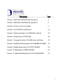
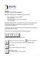
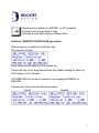
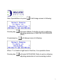
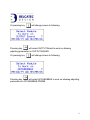
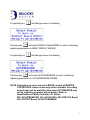
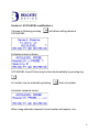
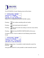
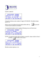
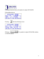
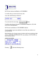
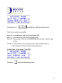
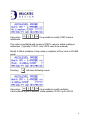
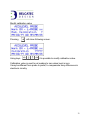
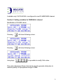
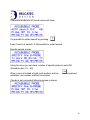
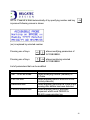
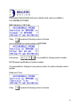
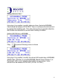
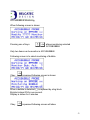
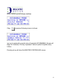
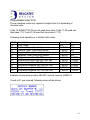
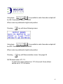
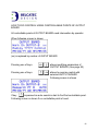
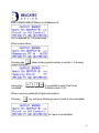
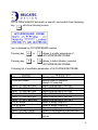
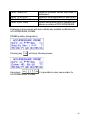
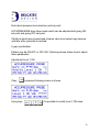
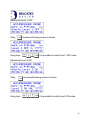
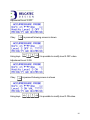
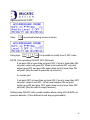
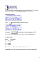
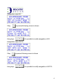
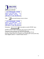
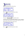
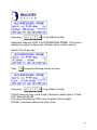
USER MANUAL
OF
MASTER CONTROLLER
PRODUCT DESCRIPTION:
Unit MASTER CONTROLLER is part of family developed by BELCATEC
DESIGN named ACCUSYSTEM.
MASTER CONTROLLER allows programming and monitoring following
modules: ACCUBUBBLE, OUTPUT BOARD, MIMIC BOARD (Series used
for ACCUBUBBLE MONITORING SYSTEM for anaerobic digester
application).
ACCULEVEL, ACCUPRESS (Series used for levels monitoring and
pressure monitoring) measuring devices for controlling of liquid level of
WIER and PARSHALL channel also PRESSURE monitoring for
compressor or other safety devices.
This manual is written in sections which describe de control and/or
operations/monitoring of connected modules.
1
PHOTO OF MASTER CONTROLLER UNIT
2
_______________Description_________________________Page____
Section 1: MASTER CONTROLLER description
4
Section 2: MASTER CONTROLLER operation’s
5
Section 3: Choice of work on module
6
Section 4: ACCULEVEL modification’s
15
Section 5: Setting variables for a PARSHALL channel
33
Section 6: Monitoring of ACCULEVEL
40
Section 7: Viewing the totals of FLUME clicks and Flows
43
Section 8: Modification/Monitoring of ACCUBUBBLE PROBE
46
Section 9: Modification/control of OUTPUT BOARD
55
Section 10: Modification of MIMIC BOARD
69
Section 11: Modification/Monitoring of ACCUPRESSURE
76
3
Section 1
MASTER CONTROLLER description
MASTER CONTROLLER is Build with following elements:
-
Micro controller running at 3MIPS
Real Time Clock
Fluorescent display: 4 lines of 20 character’s
4 keys keyboard
MASTER CONTROLLER is connected to all present modules using serial
link RS-485. Each type of modules has proprietary protocol and is
connectable using that link.
Possibility to access certain module only if programmed during fabrication
using requested list by client.
All operations are executed using only 4 buttons keyboard.
In general operations, keys are used as follow:
Return to main screen. Similar as
key on PC keyboard
Or move cursor one position to left when adjusting value.
Next choice
Or decrement value at cursor position
Preceding choice
Or increment value at cursor position
4
Selecting choice similar as <ENTER> on PC keyboard
Or move cursor one position to right.
If already at most right position, validate value.
Section 2: MASTER CONTROLLER operation’s
When power up or awake by touching a key:
This screen is shown:
Clock value may be absent (if it is a wake up)
Screen will stay on for programmed time then blanks waiting for wake up.
Clock stays on for 5 minutes.
ACCUMASTER can be set to operate in two languages FRENCH or
ENGLISH.
Pressing key may show one following screens:
French
English
5
How to set English screen:
Press
followed by
select language.
Terminate by pressing
then using
to
ACCUMASTER will reset and shows selected language. Date is shown in
selected language.
Further information’s:
When <?> is shown at most right position on third line: It is a choice.
Pressing key
will select it.
Section 3: Choice of work on module
Depending of setup code settle in ACCUMASTER following modules may
be accessed, monitor and adjusted.
Accessible modules are determined by operation code value of
ACCUMASTER in following way:
ACCUPRESSURE
ACCULEVEL
MIMIC display
OUTPUT board
ACCUBUBBLE
bit 4 (16)
bit 3 (8)
bit 2 (4)
bit 1 (2)
bit 0 (1)
Example: value (31) means all available ACCUSYSTEM modules can be
accessed.
Example: value (7) ACCUBUBBLE, OUTPUT, MIMIC only
Depending on model of ACCUMASTER some sections may not be
available.
6
One of possibilities is to press
Pressing key
Or pressing key
it will change screen to following:
will select (Master Controller) to work on allowing
adjusting parameters of MASTER CONTROLLER
(itself).
will change screen to following:
When <?> is locate at right most of third line, it is a possible choice
Pressing key
will select ACCULEVEL Probe to work on allowing
adjusting parameters in level measuring module.
7
Or pressing key
will change screen to following:
Pressing key
will select OUTPUT Board to work on allowing
adjusting parameters in OUTPUT BOARD.
Or pressing key
will change screen to following:
Pressing key
will select ACCUBUBBLE to work on allowing adjusting
parameters in ACCUBUBBLE PROBE.
8
Or pressing key
will change screen to following:
Pressing key
will select DISPLAY Board MIMIC to work on allowing
adjusting parameters in MIMIC DISPLAY BOARD.
Or pressing key
will change screen to following:
Pressing key
will select ACCUPRESSURE to work on allowing
adjusting parameters in ACCUPRESSURE PROBE.
NOTE: Depending on value entered in MODE variable of MASTER
CONTROLLER. Some screen may not be available. Preceding
screens may not be available. Also some ACCUMASTER may
not be originally programs with all modes. Refer to
identification on Micro Controller I.D. sticker.
PR= ACCUPRESSURE, LE= ACCULEVEL, MI= DISPLAY Board,
OU= OUTPUT Board, AC=ACCUBUBBLE
9
When following screen is shown and key
pressed
This screen allows accessing variables in MASTER CONTROLLER.
MASTER CONTROLLER has three adjustable functions
1- The Clock
2- The language
3- The Operation code
First choice is <Adjust Clock>
Second choice is <Language>
10
Third choice id <Operation Code>
Using following
you can select code
If screen is following pressing
will allows setting Clock values
Setting Years
<??> at right is replaced by actual value of Year.
A big block indicates position of number to change.
Using
it is possible to modify shown value.
11
More details:
Pressing
will move cursor to left
Pressing
will decrease value at cursor position by 1
Pressing
will increase value at cursor position by 1
Pressing
will move cursor to right
NOTE: If cursor is located at most right position; pressing
will
complete modification and clock adjustment will show next element.
Setting Months
Setting sequence is following:
Years, Month, Days,
Days of week (1=Sunday 7=Saturday),
Hours, Minutes, Seconds.
Note: It is not possible to get out of clock adjustment mode, you have to go
trough, but if you left unit for a while it will return to sleeping mode.
Day of week is shown in middle with two character’s SU MO TU WE
TH FR SA
12
Second choice is <Language>
If screen is following pressing
will allows setting values of language
<?> is replaced by actual choice 0 or 1 using you
used language.
can change
When button
is pressed: MASTER CONTROLLER will restart with
language selected. If your choice is FRENCH Please refer to French
manual.
Third choice is <Operation CODE>
13
If screen is preceding pressing
operation code
will allows setting values of
<??> at right is replaced by actual value of CODE.
A big block (cursor) indicates position of number to change.
Using
it is possible to modify CODE value.
Accessible modules are determined by operation code value of
MASTER CONTROLLER in following ways:
ACCUPRESSURE
ACCULEVEL
MIMIC display
OUTPUT board
ACCUBUBBLE
bit 4 (16)
bit 3 (8)
bit 2 (4)
bit 1 (2)
bit 0 (1)
Example: value (31) means all available ACCUSYSTEM modules can be
accessed.
Example: value (7) ACCUBUBBLE, OUTPUT, MIMIC only
Depending of model of ACCUMASTER some sections may not be
available.
14
Section 4: ACCULEVEL modification’s
If screen is following pressing
ACCULEVEL
will allows setting values in
Following screen is shown
ACCULEVEL (Level Probe) may be found automatically by pressing key
Or number may be entered by pressing
then set number.
Automatic research screen
When using automatic research; found number will replace <xx>.
15
If an ACCULEVEL is found, following screen will be shown.
Value in <xx> is replaced by found ACCULEVEL module.
Pressing
will continue searching with next number
Pressing
will restart search with number 01
Pressing
will select module as working on and next screen will be
shown.
Pressing
will return MASTER CONTROLLER to first screen.
If number reaches 16 and no module is found following screen will be
shown.
With this screen shown, it is possible to restart automatic research by
pressing.
Using specific research it is also possible to restart automatic research.
16
Specific research:
Using four buttons enter number of target ACCULEVEL. Permitted values
are 01-16.
When cursor is localized at most right position and key
A test to reach module is activated.
is pressed:
If researched module is not in system following screen will be shown.
NOTE: if research is made with automatic or specific, when module is found
pressing
will show next screen.
Module number replaces <xx>
17
Pressing
or
allows modifying parameters in ACCULEVEL
Pressing
or
allows listening or monitoring ACCULEVEL
List of modifiable parameters of ACCULEVEL
CHOICE
- Nbr. : of LPROBE
- Operation Mode
- Mod. : PUMP_ON time
- Mod. : PUMPOFF time
- Mod. : Lev1 ON Set Point
- Mod. : Lev1 OFF Set Point
- Mod. : Lev2 ON Set Point
- Mod. : Lev2 OFF Set Point
- Fix K1 mode
- Fix K2 mode
- Fix OPTO mode
- Mod. : OFFSET value
- Mod. : INCHES/STEP
- Mod. : MM/STEP
- Mod. : 4-20 STEP
- Mod.: Mod. CAL. Val.
- Mod.: FLUME
DESCRIPTION
Modify designation of L-Probe
Modify mode of operation
Modify time ON duration of gas pump
Modify time OFF duration of gas pump
Adjust where Level 1 turn ON
Adjust where Level 1 turn OFF
Adjust where Level 2 turn ON
Adjust where Level 2 turn OFF
Allow to assign output K1
Allow to assign output K2
Allow to assign output OPTO
Allows to set distance value from end of
tube to bottom of channel/Vessel
Allows to set step value in inches
Allows to set step value in millimeters
Allows to set multiplication of step to mA
Allows to set calibration value to get
zero value
Allows setting FLUME / WIER
parameters
18
Following screens are more information's to adjust ACCULEVEL
Probe address set-up
Pressing
will show following screen.
With keys
on RS-485 network.
it is possible to adjust ACCULEVEL address
19
NOTE: about values modification in ACCUBUBBLE
To modify value you must enter the key code
If you can read following on third line:
You must enter the code using
keys
To obtain code ask your foreman or call Belcatec Design Inc. (514) 6456353 ask for René Bellefleur.
NOTE: about modification of ACCUBUBBLE address.
It is not possible to give same address to more than one module in an
ACCUSYSTEM.
Modify address also change memory locations which are maintaining totals
of flow in MASTER CONTROLLER. MC uses address of ACCULEVEL as
base memory location.
OPERATION MODE
Pressing
will show following screen.
20
Using keys it is
possible to modify operation mode.
Only three modes are possible
Mode 0 = Level detector with gas pump always ON
Mode 1 = Level detector with control of gas pump
Mode 2 = Measuring of flow for FLUME/WEIR channel with control of gas
pump.
NOTE: In level detector mode measurement may be differential by
connecting both tubes to both sensing elements.
Working time of gas pump (Time ON)
Pressing
will show following screen.
21
Using keys
pump.
it is possible to modify operation time of
Minimum is 00001 = 1mS
Maximum is 65535 = 65.535 Sec
Note: When mode value is <0> modifying time will have no effect because
pump is always activated. When mode is 1 or 2 no measuring are
taken when pump is activated, so time shall be short, around 0.5 Sec.
(0500)
Time gas pump OFF
Pressing
will show following screen.
22
Using keys
it is possible to modify OFF pump time.
Minimum is 00001 = 1mS
Maximum is 65535 = 65.535 Sec
Note: When mode value is <0> modifying time will have no effect because
pump is always activated. When mode is 1 or 2 measurement are
taken when pump is OFF, so time shall be long, around 30 Sec.
(3000)
NOTE about detection level:
ACCULEVEL is able to detect two different levels (LEV1, LEV2) each set
point are arranged with turn ON and turn OFF.
If both points are programmed with same value output assigned to it may
become unstable when level is around set points.
Having a gap is recommended.
Operations may be ON-OFF or OFF-ON. Next figures show how to do
those settings.
23
Set point LEV1 ON
Pressing
will show following screen.
Using keys
point.
it is possible to modify LEVEL 1 ON set
Set point LEV1 OFF
Pressing will
show following screen.
24
Set point LEV1 OFF
Using keys
point.
it is possible to modify LEVEL 1 OFF set
Set point LEV2 ON
Pressing
Using keys
point.
will show following screen.
it is possible to modify LEVEL 2 ON set
25
Set point LEV2 OFF
Pressing
will show following screen.
Using keys
point.
it is possible to modify LEVEL 2 OFF set
NOTE: About operating ON-OFF OFF-ON levels:
If set point ON is lower than set point OFF, if level is lower than ON
set point, output will goes ON. When level reaches OFF set point,
output goes OFF and goes ON again when level is lower than ON
set point. (May be used to fill up a reservoir)
In counter part:
If set point OFF is lower than set point ON, if level is lower than OFF
set point, output is set OFF. When level reaches ON set point,
output goes ON and goes OFF again when level is lower than OFF
set point. (May be used to empty a reservoir)
Setting values ON-OFF with small variation allows using ACCULEVEL as
level detector. (Two different levels are programmable)
26
Assignation output K1
Pressing
will show following screen.
Using keys
it is possible to modify assignation of output K1.
Five modes are available for three ACCULEVEL outputs
K1, K2 and OPTO
Mode
Description
0= Control for gas pump
1= Level 1
2= Level 2
3= FLUME pulse
4= always ON
More then one output may be assigned to same controlled element
Depending of model some output may be absent.
27
Assignation output K2
Pressing
will show following screen.
Using keys
it is possible to modify assignation of output K2.
Assignation output OPTO
Pressing
will show following screen.
28
Using keys
OPTO
it is possible to modify assignation of output
Modify OFFSET value
Pressing
Using keys
will show following screen.
it is possible to modify OFFSET
OFFSET VALUE is added to measured value to obtain real position.
Tube immersed in liquid is normally not placed at bottom of measuring
point, usually at ¼ inches or more. OFFSET value is used to compensate
tube position.
29
Modify STEP value in INCHES
Pressing
Using keys
inches
will show following screen.
it is possible to modify STEP value in
This value is multiplied with measured STEP’s value to obtain reading in
inches. (Typically 0.01250, Enter 01250)
Modify STEP value in MILLIMETERS
Pressing
will show following screen.
30
Using keys
millimeters.
it is possible to modify STEP value in
This value is multiplied with measure STEP’s value to obtain reading in
millimeters. (Typically 0.33510, only 33510 need to be entered)
Modify 4-20mA multiplier of step value or multiplier of flow value in FLUME
mode.
Pressing
will show following screen.
Using keys
it is possible to modify multiplier.
Value entered is with 3 decimal. Value possible: 00.001 up to 65.535
31
Modify calibration value
Pressing
Using keys
will show following screen.
it is possible to modify calibration value.
Calibration value is used to set reading to zero when level is zero
It may be different from probe to probe, to compensate tinny differences in
electronic circuitry
32
Available only if ACCULEVEL is configured to read FLUME/WIER channel.
Section 5: Setting variables for PARSHALL channel
Modification of FLUME values
Pressing
will show following screen.
Pressing
will show following screen.
Using keys
it is possible to modify Click value.
This value determines Flume click and is used to generate click pulse to
totalize quantity of liquid passed trough FLUME.
33
How to find good value which is in relation with others values of FLUME
measurement.
Such as: Tables FLUME correction values
Value between points of curve.
Frequency of CLICK’s
NOTE: Click value allows determining and recording flow passing trough
channel. This value may be 10, 100, 1000 liters, gallons, cubic
feet, cubic meter or others
Frequency when channel is at maximum capacity shall not exceed
2 pulses (CLICK) per second.
Click counters are memorized in non volatile memory located in
MASTER CONTROLLER. All counters cannot be cleared by
MASTER CONTROLLER which holds accumulator of 20 digits.
Eight accumulator values (1 per day with preceding week day) 16
digit accumulators are recording day’s values which are cleared at
beginning of actual day.
Day changes every time clock shows 00:00 hrs.
FLUME curve can be corrected using 30 steps which allow
computation with very small error.
Values of flow are computed every 62.5 millisecond or 16 times
per second. At each 62.5 millisecond height reading is measured.
If value is corresponding to a multiple of heights set in table then
value from table is add to accumulator. If accumulator reaches
value of CLICK then CLICK is generated and click information is
sent to MASTER CONTROLLER which will record value in
34
corresponding memory block. Accumulators are not reset keeping
their values; which is working as a linear extrapolation.
Following shows 100 gallons (UK) click using flume of 9” inches wide. Value
of table are entered with one decimal
Parameters: Between point height 24"/30 = 0.8”
Gallon per minute US /0.7505703 = Gpm UK
Height inches
0.8
1.6
2.4
3.2
4.0
4.8
5.6
6.4
7.2
8
8.8
9.6
10.4
11.2
12
12.8
13.6
14.4
15.2
16
16.8
17.6
18.4
19.2
20
20.8
21.6
22.4
23.2
24
Decimal foot
0.0666
0.1333
0.2
0.2666
0.3333
0.4
0.4666
0.5333
0.6
0.6666
0.7333
0.8
0.8666
0.9333
1
1.0666
1.1333
1.2
1.2666
1.333
1.4
1.4666
1.533
1.6
1.6666
1.7333
1.8
1.8666
1.9333
2
Gp/M US
19.1
64.0
117.0
180.0
254.0
339.5
427.3
532.4
630.6
730.2
850.4
980.2
1110.2
1235.6
1382.4
1517.4
1679.6
1821.1
1963.4
2142.9
2301.1
2460.6
2643.0
2839.5
3006.8
3198.1
3386.6
3565.2
3780.1
3976.4
Gp/M UK
13.8
41.1
84.3
129.7
183.0
244.6
307.9
383.6
454.4
526.2
612.8
706.3
800.0
890.3
996.1
1094.8
1210.3
1312.2
1414.8
1544.1
1658.1
1773.0
1904.5
2046.1
2166.6
2304.5
2440.3
2569.0
2723.8
2865.3
35
Table of gallons per minute UK shall be chosen because numbers are
bigger. Maximum value of ACCULEVEL is 65535. Allowing entering values
with one decimal, maximum is 28653= 2865.3.
Figure shows bloc of value to be entered to set FLUME 24 inches high by 9
inches wide. If click represent 100 gallons UK, frequency can be computed
by 2856.3/60/100 = 0.644 sec. 1.56 Click par second.
Value of click is computed by: 16 (62.5mSec) * 60 (Value in GPM) * 10
(decimal) * 100 (units) =960000. Maximum value of FLUME CLICK is
16711680 then acceptable. If value required is in cubic meters: we just
have to convert CLICK value respecting maximum value allowed.
This table is available by using PC and ACCUSYSTEM software.
It is possible to enter values in ACCULEVEL using MASTER
CONTROLLER too.
36
Pressing
will show following screen.
Using keys
it is possible to modify FLUME step value.
(Value between steps of flume in height of liquid, multiple of 0.0125")
Pressing
will show following screen.
37
Using keys
it is possible to modify all FLUME point (30)
values. By the fact adjusts curve of FLUME.
To allow ACCULEVEL to compute flow values it needs a conversion factor
with decimal position. Figure shows conversion factors if FLUME is
calibrated in Gallons per minutes (UK).
38
Two following screen allows to set conversion factors
Pressing
will show following screen.
Pressing
will show Programmed value.
Using Keys
it is possible to modify conversion factor
of ACCULEVEL for each available
Flow measurement.
When value is validated following screen is shown. You can adjust decimal
value. Number of decimal may be changed if required.
NOTE: Do not forget that decimal value must include decimal we used in
entering FLUME step values.
39
NOTE: FLUME CLICK is used to record quantity of liquid passed trough
flume. Flow is only information in real time of how many units of
liquid is passing trough.
Section 6: Monitoring ACCULEVEL
If one of those keys
is pressed following screen will show.
If key
is pressed next screen shows actual value in STEP of
ACCULEVEL
(xx) is replaced by value of STEP
One step usually equal 0.0125” water column.
40
STEP’s are transformed in inches
If key
is pressed next screen shows actual value in inches.
If key
is pressed next screen shows actual value in millimeters
41
If key
is pressed next screen shows actual value in mA (0-65535)
of ACCULEVEL mA output. 4mA=0
If key
is pressed the <?> will be replaced by a big bloc every time
MASTER CONTROLLER receives FLUME click from ACCULEVEL. This
screen will stay on for 5 minutes and will be cleared. Big block is ON for 0.5
sec.
42
Section 7: Viewing the totals of FLUME clicks and Flows
If key
is pressed next screen will show total of FLUME CLICK’s.
The 20 digits total click cannot be reset
Days are shows by SU, MO, TE, WE, TH, FR, SA & PD
PD IS THE DAY BEFORE last week day.
Actual day accumulator is cleared when clock show 00:00.
43
If key
is pressed next screen will show FLOW.
All following readings are available:
L/S
L/M
L/H
M3/M
M3/H
P3/S
P3/M
P3/H
GUK/S
GUK/M
GUK/H
GUS/S
GUS/M
GUS/H
MGUK/J
MGUS/J
M-M3/J
Liter per Second
Liter per minute
Liter per hour
Cubic Meter per minute
Cubic Meter per hour
Cubic Foot per second
Cubic Foot per minute
Cubic Foot per hour
Gallon UK per second
Gallon UK per minute
Gallon UK per hour
Gallon US per second
Gallon US per minute
Gallon US per hour
Thousand Gallons UK par jour
Thousand Gallons US par jour
Thousand Meters cube par jour
Because units are converted any other engineering value may be
programmed on request.
44
To read Liter per Second
If key
Second.
is pressed following screen will show value of Litre per
Note: precision is with 3 decimals even if computation is with 10 decimals
over decimals are not shown.
45
Section 8: Modification/Monitoring of ACCUBUBBLE PROBE
ACCUBUBBLE (BUBBLE PROBE) is used to monitor bubble emission in
vertical tube used in an anaerobic digester to mix liquid in digester.
See Technical manual ACCUBUBBLE for more details
In ACCUBUBBLE monitoring system MASTER CONTROLLER is
communicating with ACCUBUBBLE PROBE's and can programs or
monitors each installed probe.
This section describe possible operations and their usages
When following screen is shown
If key
is pressed it allow adjusting parameters of ACCUBUBBLE
(BUBBLE PROBE).
Following screen is shown
46
Probe may be reached automaticaly if key
is pressed.
Or probe number may be entered with keyboard if key
is pressed.
Screen of automatic search
Automatic search will shows instead of (??) number of searched probe.
When an ACCUBUBBLE probe is found following screen is shown.
As example probe 4 is found
If Key
is pressed search continue with next number.
If Key
is pressed search restart with number 01
If Key
is pressed probe is selected to work on and next screen is
shown. (See page 49)
If Key
is pressed Master Controller go back to first screen.
47
If searched module is not found screen will show
It is possible to restart search by pressing
Even if search is specific, It still possible to restart search
Specific search screen
Using four keys you can enter number of specific probe to work ON.
(Possible value: 01 – 60)
When cursor is located at right most position and key
validation over number entered is executed.
is pressed
If probe is not connected following screen is shown.
48
NOTE: If search is done automatically of by specifying number and key
is pressed following screen is shown.
(xx) is replaced by selected number
Pressing one of keys
allows modifying parameters of
ACCUBUBBLE.
Pressing one of keys
allows monitoring selected
ACCUBUBBLE
List of parameters that can be modified
CHOICE
- Nbr. : of the BPROBE
- LED ON time
- Debounce time
- PERIOD transfer time
DESCRIPTION
Allows modifying number (Address) of
B-Probe
Allows adjusting time of local LED is ON
(Activity indicator)
Allows adjusting time when B-Probe is not
sensing after bubble has been detected
Allows adjusting time of automatic
sequencer which send PERIOD to
RS-485 communication line
49
Following screens shows with more details what can be modified in
ACCUBUBBLE PROBE.
NBR (address) of B-Probe
If key
is pressed folowing screen is shown
(xx) is replaced by actual number of BPROBE
Using keys,
it is possible to change probe number.
NOTE about modification of probe number:
It is impossible to change to new probe number if number already exist in
system
Debounce Time
If key
is pressed folowing screen is shown
50
Setting debounce time
Using keys it is possible to modify debounce time of selected BPROBE.
Value should be between 200 & 2000. Time is in milisecond and should not
be greater than bubbling rate. This value stops probe to generate detection
after bubble was detected to prevent eratic reading of bubbler.
Setting LED ON time in BPROBE
If key
is pressed folowing screen is shown
Using keys it is possible to modify time when LED located atop of BPROBE
(Model Class I Division 2) or inside BPROBE (Model Class I Division 1) is
illuminated. LED is local indication that bubble was generated. Value
entered must be between 200 & 5000 (.02 Sec. to 5 Sec.)
51
Setting repetitive transfer timing of period value
If key
is pressed folowing screen is shown
Using keys
it is possible to modify transfer time of
period value (time between bubbles) this function is not used with MASTER
CONTROLLER but required when ACCUSYSTEM SOFTWARE is used
(Refer to software for more details) Accepted value is between 5000 and
60000. (5 seconds to 60 seconds)
52
ACCUBUBBLE Monitoring
When following screen is shown
Pressing one of keys
allows monitoring selected
ACCUBUBBLE
Only two items can be monitor in ACCUBUBBLE
Following screen is to select monitoring of bubble.
If key
is pressed following screen is shown
When a bubble is detected (_) is replaced by a big block.
Big block stays ON for one second.
Display is shown for 5 minutes
If key
is pressed following screen will show
53
MONITORING period between bubbles
If key
is pressed folowing screen is shown
(xx.xxx) is replaced by period value of selected ACCUBUBBLE. Screen will
stays for 5 minutes, if no key is pressed. Value of period is update every
0.5Sec.
Pressing a key will show first MASTER CONTROLLER screen.
54
Section 9: Modification/control of OUTPUT BOARD
OUTPUT BOARD included in ACCUSYSTEM is primarily used to interface
signals from ACCUBUBBLE's to outside world. Those signals can be
connected to PLC allowing SCADA to be implemented.
OUTPUT BOARD can also be used to implement control to elements using
output lines programmed as alarms for too short or too long period of
ACCUBUBBLE's.
Output lines may also programmed to be used as control lines for switching
ON-OFF elements, one shot timers or sequencers
Polarity of signals may be positive or negative.
See: Technical manual of OUTPUT BOARD for more details
In installation of an ACCUSYSTEM monitoring bubbles or others, MASTER
CONTROLLER can communicate with OUTPUT BOARD and programs
each of 24 points available.
This section describes such operations and their possible usages.
When following screen is shown
If key
is pressed it activate this choice and allows changing OUTPUT
BOARD parameters
Next screen will be shown.
55
Selection of OUTPUT BOARD
OUTPUT BOARD may be automaticaly reasearch by pressing key
or number specified using key
AUTOMATIC search screen
During automatic search (xx) is replaced by found module
If an OUTPUT BOARD is found following screen is shown.
Example show finding of OUTPUT BOARD # 03
If Key
is pressed search continue with next number.
If Key
is pressed search restart with number 01
If Key
is pressed OUTPUT is selected to work on and next screen
is shown. (See page 58)
If Key
is pressed Master Controller go back to first screen.
56
If OUTPUT is not found following screen is shown
With that screen it is possible to restart an auto search starting with 01 by
pressing
Even if it is a specific research restarting an auto search is possible.
Specific search screen
Using four key, it is possible to enter number of specific O-B (Permissible
value 01-16)
When cursor is located at most right position pressing
research on specific module.
will start a
If research in not successful following screen will be shown
NOTE: If search was executed automatically or specifically and key
pressed following screen is shown.
57
OUTPUT BOARD choice of operation
Number of O-B replaces the (xx)
Pressing one of keys
allows modifying parameters of
OUTPUT BOARD.
Pressing one of keys
allows exercising control with
selected OUTPUT BOARD
If one of keys
or
parameters is selected.
is pressed modification of OUTPUT
58
For reference information’s, picture of ACCUSYSTEM software in
programming of OUTPUT BOARD.
OUTPUT BOARD is build with 24 (OUT POINT), 18 operating modes per
point & 3 time bases.
First operation is to select point to work on. Following screen allows
choosing select point.
59
If key
is pressed allows selecting POINT to be modified. following
screen is shown
Using keys,
it is possible selecting point to work ON.
When cursor is positioned at right most position:
Pressing
key allows selecting point wich can be modified.
Modification of POINT must be completed before anotherone can be
selected.
Following screen is shown
Using the keys,
ACCUBUBBLE
(Permitted value 00-60)
it is possible to select which
is assigned to that point
When cursor is positioned at right most position:
Pressing
key select point with ACCUBUBBLE assignation.
60
If value B-PROBE is 00 this select control mode (no ACCUBUBBLE is
selected). See page 63
Following screen is shown
9 codes can be programmed (00-08). Actual code is shown at place of (??).
If code is not permitted it will be replaced by 00
(NO OPERATION)
Using keys,
(00-08)
it is possible to enter desired code
When cursor is positioned at right most position:
Pressing
key allows continue setting of point.
If code selected is 00 see page 59. Selection of point
Following is continuing of parameters modification, setting of time #1
(if code is not 00)
Following screen is shown
Using keys,
it is possible to enter time that output is
activated.
Permissible value: 01-65535.
When cursor is positioned at right most position:
Pressing
key if mode is 01 or 03 see page 59 Point Selection.
61
If code is 03, 04, 05, 06 you must set time #3. Duration of sustain alarm.
Following screen is shown
Using keys,
when alarm
it is possible to enter time of sustain alarm
is deactivated. (Permissible value 01-255)
When cursor is positioned at right most position:
Pressing
key will show selection of point See page 59
DESCRIPTION OF POSSIBLE CODE From 0 to 8
Operation
Code
0
1
2
3
4
5
6
7
8
Description
NO Operation
Positive Follow of PROBE nbr. with T1
Negative Follow of PROBE nbr with T1
Alarm: period too short positive PROBE nbr with T1—T3
Alarm: period too short negative PROBE nbr with T1—T3
Alarm: period too long positive PROBE nbr with T1—T3
Alarm: period too long negative PROBE nbr with T1-T3
Alarm period too short or too long positive PROBE nbr with
T1—T2—T3
Alarm period too short or too long negative PROBE nbr with
T1—T2—T3
62
If code is 07 or 08, time #2 may be adjusted. Value of time is long limit of
combined alarm. Following screen is shown
Using keys,
period.
Pressing
it is possible to enter time of too long
(Permissible value 01-65535)
key will show point selection. See page 59
If B-PROBE is 0, it is possible to program controlable points.
11 control codes are available (16-26). Possible code are shown by
replacing the (??). If code is imposible it will be replaced by 00.
If code is 16, It is possible to activate or desactivate output.
See page 68
If code is 17, 18, 19, 20, one time delay is available. It is possible to start or
stop delay using control section. See page 68
If code is 21 to 26, sequencer ON-OFF can be programmed, Started or
stopped using control section. See page 68
63
Programmable codes 16-26
Those operation mode may requierd to adjust time 0-2 depending of
choosen code.
Code 16 (DIRECT DATA) do not need time value. Code 17-20 need one
time base (T1). Code 21-26 need two time base (t1.T2)
Following show operation,s in relation with codes
CODE
16
17
18
19
20
21
22
23
24
25
26
Description
Direct Data
Positive Timer (One shot) second
Positive Timer (One shot) minute
Negative Timer (One shot) seconds
Negative Timer (One shot) minute
Sequencer positive ON-OFF sec. sec
Sequencer positive ON-OFF min. sec
Sequencer positive ON-OFF min. min
Sequencer negative OFF-ON sec. sec
Sequencer negative OFF-ON sec. min.
Sequencer negative OFF-ON min. min
Time 1
n/a
1-65535
1-65535
1-65535
1-65535
1-65535
1-65535
1-65535
1-65535
1-65535
1-65535
Time 2
n/a
n/a
n/a
n/a
n/a
1-65535
1-65535
1-65535
1-65535
1-65535
1-65535
Example of sequencer positive ON-OFF second, second. CODE 21
If code is 21 was entered, following scren will be shown.
64
Using keys,
it is possible to enter time when output will
be ON. Permissible values 01-65535
When cursor is positioned at right most position:
Pressing
key will show following screen.
Using keys,
it is possible to enter time when output will
be OFF. Permissible values 01-65535
When cursor is positioned at right most position:
Pressing
key will Show selection screen. See page 59
NOTE about value of T1-T3:
In most case value entered is in 1/10 of second. Some others
entries are in 1/10 of minute.
65
HOW TO DO CONTROL USING CONTROLLABLE POINTS OF OUTPUT
BOARD
All controllable points of OUTPUT BOARD need intervention by operator.
When following screen is shown
(xx) is replaced by number of OUPUT BOARD
Pressing one of keys
allows modifying parameters of
OUTPUT BOARD. (See page 58)
Pressing one of keys
allows to exercise control with
selected OUTPUT BOARD
Following screen is shown
If key
is pressed an auto search is start to find first controllable point.
Following screen is shown if no controllable point is found.
66
End of search without finding controllable point.
(xx) is replaced by 1-24 point value
When screen show:
Pressing key
screen is shown
Using keys,
controlled.
allows entering point number to control it. Following
it is possible to enter Point to be
Possible value 01-24
When cursor is positioned at right most position:
Pressing
key will show following screen if point is not controllable
or if point is controllable:
67
Point is controlable
Pressing key
point will be set to OFF or STOP
Pressing Key
point will be set to ON or START
If key
is pressed start research for next controllable point will
If key
screen.
is pressed screen will show first MASTER CONTROLLER
Note: Belcatec Design Inc. never intend to build PLC using OUTPUT
BOARD and MASTER CONTROLER but just allows first line control
using few parts. Basic idea is to be able to control cleaning valves for
bubbles generator or other accessories.
68
Section 10: Modification of MIMIC BOARD
Function of MIMIC BOARD display is to show in real time and in centralized
point activity of BUBBLE generators, using bubble mixer in anaerobic
digester. Display is usually built using LED's which are illuminated when
bubble is detected by ACCUBUBBLE PROBE. Because of most different
installation LED panel construction is adapted for installation. MIMIC
BOARD module allows this installation adaptation.
MASTER CONTROLLER allows adjusting parameters in relation of
installation.
MIMIC board can accommodates 40 LED's in scheme 8 rows by 5 columns.
Usually it is not needed to do modification in that arrangement (It is factory
configured by Belcatec Design Inc.) The Next screen allows making
adjustment to original set-up.
Section describe how to make modifications and their usages
When following screen is shown
Pressing key
activate choice allowing to configure MIMIC BOARD
Up to 16 MIMIC BOARD may be installed in ACCUSYSTEM
Following screen is SHOWN.
69
Selecting MIMIC BOARD
MIMIC May be researched automatically by pressing
Or enter specific number by pressing
AUTO search of mimic.
During auto search module number will replace (xx)
If MIMIC BOARD is found following screen is shown
Example MIMIC BOARD #3
If key
is pressed search goes on
If key
is pressed search restart with 01
70
If key
is
is pressed module is chosen to work on and following screen
shown Page 74 (CHANGE NUMBER)
If key
is pressed MASTER CONTROLLER show first screen.
In case search module is not present following screen is shown
With this screen shown it is possible to restart auto search by pressing
If search was specific it is also possible to restart automatic search
Specific search
Using the four keys it is possible to enter number of mimic to work with.
(Permissible value 01-16)
When cursor is located at most right position pressing
search to validate specified MIMIC BOARD.
will start
71
If module is not found following screen is shown
NOTE if search was Specific or Automatic pressing key
following screen
will show
Selected number will replace (xx)
Pressing
allows modifying number of module MIMIC BOARD
(See next page)
Pressing
will show following screen to adjust LED on timing
Pressing
allows modifying illumination time of LEDs
(See page 75)
72
Pressing
shows following screen to adjust assignation of
ACCUBUBBLE to LED.
Entire set of 40 LEDs must be completed to get out of this mode
Number of LED is shown in place of (xx)
Using the four keys it is possible to enter number of ACCUBUBBLE which
will illuminates LED Permissible value 00-60.
If 00 is entered LED is not assigned and will remain off.
Following figure for reference only; is part of ACCUSYSTEM SOFTWARE
use on PC to program MIMIC BOARD.
73
In software screen only 13 ACCUBUBBLEs are present using two rows
When last position (40) is adjusted starting screen of MASTER
CONTROLLER is shown.
Modify number of MIMIC BOARD
Using the four keys it is possible to modify number (address) of MIMIC
BOARD
NOTE about changing number of MIMIC BOARD:
If number already exists in system trying to use same will not work. Same
address can not be applied for more then one module.
When cursor is localized at right most position of digit and key
is pressed Master Will try to find module with same address, If not
found module number will be changed and following screen is shown.
Pressing key
allows modifying time LEDs are illuminated
74
Adjustment of time LEDs are ON
Using keys
LEDs are
it is possible to modify time period where
turn ON
Acceptable value must be between 200 & 5000 (0.2Sec to 5 Sec)
When cursor is located at right most position and key
is pressed
modifications will continue with assignation of ACCUBUBBLE to LED's See
page 73
NOTE it is possible to assign more than one LED to same
ACCUBUBBLE.
75
Section 11: Modification/Monitoring d'ACCUPRESSURE
ACCUPRESSURE module is used for pressure sensor & controller for
measuring vacumm/pressure. This is ideal equipment to secure gas
compressor in installation of gas recirculation in anaerobic digester. Using
two modules, one for entry (Suction) and one at exit (Pressure), a security
system with digital and analog signals can be implemented.
It is also possible using ACCUPRESSURE to control pressure in low
pressure reservoir.
MASTER CONTOLER allows changing parameters in ACCUPRESSURE.
Similar as ACCULEVEL; ACCUPRESSURE may be used in process
control of other equipments. Most of the operations are similar of
ACCULEVEL.
When following screen is shown and
is pressed
Following screen is shown
Pressing
will search automatically to find PRESSURE PROBE
or number may be entered manually by pressing
76
Automatic research screen
During automatic research number search for is replacing (xx)
If ACCUPRESSURE is present following screen is shown.
Example ACCUPRESSURE #04
Pressing key
will continue research
Pressing key
will restart research with module 01
Pressing key
will select module to work on and following screen is
shown (last of next page)
Pressing key
will return MASTER CONTROLLER to it first screen
77
In case search module is not present following screen is shown
It is possible to restart search by pressing key
If it was specific search it still possible to restart auto searches.
Specific research
Using the four keys it is possible to enter number of ACCUPRESSURE to
work on (permissible value 01-16)
When cursor is located at most right digit pressing key
search for that module
will initiate
If module is not present following screen is shown
78
NOTE: Either search is automatic or specific, and module found pressing
key
will show following screen.
(xx) is replaced by ACCUPRESSURE number
Pressing key
or
allows to modify parameters of
ACCUPRESSURE PROBE.
Pressing key
or
allows to listen (Monitor) selected
ACCUPRESSURE PROBE.
Following list of modifiable parameters of ACCUPESSURE PROBE
CHOICE
- Nbr. : of PPROBE
- Operation Mode
- Mod. : P1 ON Set Point
- Mod. : P1 OFF Set Point
- Mod. : P2 ON Set Point
- Mod. : P2 OFF Set Point
- Mod. : P3 ON Set Point
- Mod. : P3 OFF Set Point
- Fix K1 mode
- Fix K2 mode
- Fix OPTO mode
- Mod. : OFFSET value
- Mod. : INCHES/STEP
DESCRIPTION
Modify address of P-Probe
Modify mode of operation
Always (0) reserved
Adjust PRESSURE 1 turn ON
Adjust PRESSURE 1 turn OFF
Adjust PRESSURE 2 turn ON
Adjust PRESSURE 2 turn OFF
Adjust PRESSURE 3 turn ON
Adjust PRESSURE 3 turn OFF
Allow to assign output K1
Allow to assign output K2
Allow to assign output OPTO
Allows to set negative (Vacuum) limit
Allows to set water column step value in
inches
79
- Mod. : MM/STEP
- Mod. : 4-20 STEP
- Mod.: Mod. CAL. Val.
- Mod.: ENG. Value
Allows to set water column step value in
millimeters
Allows to set multiplication of step to mA
Allows to set calibration value to get zero
Allows setting what type of measure are
shown on screen of ACCUPRESSURE
Following screens shows with more details any possible modification to
ACCUPRESSURE PROBE.
PROBE number (designation)
Pressing key
will show following screen
Using keys
ACCUPRESSURE PROBE.
it is possible to enter new number for
80
Note about modification of parameters of P-PROBE:
Modification of P-PROBE are requiring unlocking numbered key
If on third line you can read:
Using keys
it possible to enter key numbers
To obtains key code ask your foreman or call Belcatec Design Inc. (514)
645-6353 (Ask for René)
Modification of module number is not possible if in system number already
exist.
81
Note about pressure level detection and set point.
ACCUPRESSURE have three levels which can be adjusted with going ON
set point and going OFF set point.
If both set points are programmed at same value level output may become
unstable when pressure is reached.
A gap is preferable.
Pattern may be ON-OFF or OFF-ON. Following screen shows how to adjust
those parameters.
Adjustment Level 1 ON
If key
Using keys
is pressed folowing screen is shown
it is possible to modify level 1 ON value.
82
Adjustment Level 1 OFF
If key
is pressed folowing screen is shown
Using keys
it is possible to modify level 1 OFF value.
Adjustment Level 2 ON
If key
Using keys
is pressed folowing screen is shown
it is possible to modify level 2 ON value.
83
Adjustment Level 2 OFF
If key
is pressed folowing screen is shown
Using keys
it is possible to modify level 2 OFF value.
Adjustment Level 3 ON
If key
Using keys
is pressed folowing screen is shown
it is possible to modify level 3 ON value.
84
Adjustment Level 3 OFF
If key
is pressed folowing screen is shown
Using keys
it is possible to modify level 3 OFF value.
NOTE: Over operating ON-OFF OFF-ON levels:
If set point ON is lower than set point OFF, if level is lower than ON
set point, output will goes ON. When level reaches OFF set point,
output goes OFF and goes ON again when level is lower than ON
set point. (May be used to pressure up reservoir)
In counter part:
If set point OFF is lower than set point ON, if level is lower than OFF
set point, output is set OFF. When level reaches ON set point,
output goes ON and goes OFF again when level is lower than OFF
set point. (May be used to empty reservoir)
Setting value ON-OFF with a small variation allows using ACCULEVEL as
pressure detector. (Three different levels are programmable)
85
ACCUPRESSURE is assembled with three digital output (K1, K2, OPTO)
See Technical Manuel of ACCUPRESSURE for more details)
Assignation output K1
If key
is pressed folowing screen is shown
Using keys
it is possible to modify assignation of K1.
Four modes are available for three outputs of ACCUPRESSURE
K1, K2 & OPTO
Mode
Description
0= Always OFF
1= Level 1
2= Level 2
3= Level 3
More than one output may be affected at same Level
Depending on ACCUPRESSURE model some output may be absent.
86
Assignation output K2
If key
is pressed folowing screen is shown
Using keys
it is possible to modify assignation of K2
Assignation output OPTO
If key
Using keys
is pressed folowing screen is shown
it is possible to modify assignation of OPTO
87
Adjustment of OFFSET
If key
Using keys
is pressed folowing screen is shown
it is possible to modify OFFSET value.
OFFSET value is used to set lowest value (Vacuum value in step)
This is also lower reading of ACCUPRESSURE probe.
OFFSET value determined value Zero for output analog 4-20 mA
Entering 0 means there is no negative value; Entering 80 means probe may
show negative value of -1 inches of water column.
88
Adjust inches (water column) value per step
If key
Using keys
is pressed following screen is shown
it is possible to modify
inches/step value of ACCUPRESSURE PROBE. This value is multiply by
value of step to obtain measure in inches of water column (Typ. 0.0125)
Adjust millimeter (water column) value per step.
If key
is pressed following screen is shown
89
Using keys
it is possible to modify
millimeters value per STEP of ACCUPRESSURE PROBE. This value is
multiply by number of step to get millimeter value of water column
Adjust 4-20 mA per step
If key
Using keys
is pressed following screen is shown
it is possible to modify
4-20mA value per step. Value is with 3 decimal to obtain gain of 1 Enter
1000, Max gain 65.535
This value is multiply by STEP value to obtain 4-20ma output
OFFSET is used as reference for 4ma. (Zero)
90
Adjustment of value shows on display of ACCUPRESSURE PROBE.
12 ways are available.
Value
0
1
2
3
4
5
6
7
8
9
10
11
DISPLAY
RAW
IWC
FWC
CWC
PSI
OSI
IHG
MHG
KPA
KCM
MBR
BAR
DESCRIPTION
STEP of 0.0125” water column
Inches Water Column
Feet Water Column
Centimeter Water Column
Pound Square Inches
Once Square Inches
Inches Mercury
Millimeter Mercury
Kilo Pascal
Kilograms square Centimeter
Milli Bar
Bar
Adjustment of ENG value to show on PROBE display
If key
Using keys
is pressed folowing screen is shown
it is possible to modify
way PROBE show measured value on display.
91
MONITORING ACCUPRESSURE PROBE
When following screen is shown
(xx) is replaced by number of P-Probe
Pressing
or
allows Listening value read by probe.
Only one screen is shown in monitoring mode
Output value (?) 1=ON 0=OFF
(nnn) ENG value type
(xxxxx.xxx) Pressure value
Screen is refreshed every 0.5 sec.
Last Revision DEC 2007
File MANUEL Doperation MCEN.doc
92