1
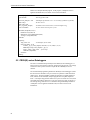
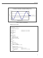
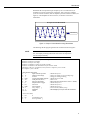
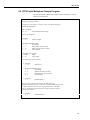
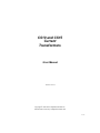
CS10 and CS15
Current
Transformers
User Manual
Issued: 16.4.12
Copyright © 2001-2012 Campbell Scientific Inc.
Printed under Licence by Campbell Scientific Ltd.
CSL 852
Guarantee
This equipment is guaranteed against defects in materials and workmanship.
This guarantee applies for twelve months from date of delivery. We will
repair or replace products which prove to be defective during the guarantee
period provided they are returned to us prepaid. The guarantee will not apply
to:
•
Equipment which has been modified or altered in any way without the
written permission of Campbell Scientific
•
Batteries
•
Any product which has been subjected to misuse, neglect, acts of God or
damage in transit.
Campbell Scientific will return guaranteed equipment by surface carrier
prepaid. Campbell Scientific will not reimburse the claimant for costs incurred
in removing and/or reinstalling equipment. This guarantee and the Company’s
obligation thereunder is in lieu of all other guarantees, expressed or implied,
including those of suitability and fitness for a particular purpose. Campbell
Scientific is not liable for consequential damage.
Please inform us before returning equipment and obtain a Repair Reference
Number whether the repair is under guarantee or not. Please state the faults as
clearly as possible, and if the product is out of the guarantee period it should
be accompanied by a purchase order. Quotations for repairs can be given on
request. It is the policy of Campbell Scientific to protect the health of its
employees and provide a safe working environment, in support of this policy a
“Declaration of Hazardous Material and Decontamination” form will be
issued for completion.
When returning equipment, the Repair Reference Number must be clearly
marked on the outside of the package. Complete the “Declaration of
Hazardous Material and Decontamination” form and ensure a completed copy
is returned with your goods. Please note your Repair may not be processed if
you do not include a copy of this form and Campbell Scientific Ltd reserves
the right to return goods at the customers’ expense.
Note that goods sent air freight are subject to Customs clearance fees which
Campbell Scientific will charge to customers. In many cases, these charges are
greater than the cost of the repair.
Campbell Scientific Ltd,
Campbell Park, 80 Hathern Road,
Shepshed, Loughborough, LE12 9GX, UK
Tel: +44 (0) 1509 601141
Fax: +44 (0) 1509 601091
Email: [email protected]
www.campbellsci.co.uk
PLEASE READ FIRST
About this manual
Please note that this manual was originally produced by Campbell Scientific Inc. primarily for the
North American market. Some spellings, weights and measures may reflect this origin.
Some useful conversion factors:
Area: 1 in2 (square inch) = 645 mm2
Length:
1 in. (inch) = 25.4 mm
1 ft (foot) = 304.8 mm
1 yard = 0.914 m
1 mile = 1.609 km
Mass:
1 oz. (ounce) = 28.35 g
1 lb (pound weight) = 0.454 kg
Pressure:
1 psi (lb/in2) = 68.95 mb
Volume:
1 UK pint = 568.3 ml
1 UK gallon = 4.546 litres
1 US gallon = 3.785 litres
In addition, while most of the information in the manual is correct for all countries, certain information
is specific to the North American market and so may not be applicable to European users.
Differences include the U.S standard external power supply details where some information (for
example the AC transformer input voltage) will not be applicable for British/European use. Please
note, however, that when a power supply adapter is ordered it will be suitable for use in your country.
Reference to some radio transmitters, digital cell phones and aerials may also not be applicable
according to your locality.
Some brackets, shields and enclosure options, including wiring, are not sold as standard items in the
European market; in some cases alternatives are offered. Details of the alternatives will be covered in
separate manuals.
Part numbers prefixed with a “#” symbol are special order parts for use with non-EU variants or for
special installations. Please quote the full part number with the # when ordering.
Recycling information
At the end of this product’s life it should not be put in commercial or domestic refuse
but sent for recycling. Any batteries contained within the product or used during the
products life should be removed from the product and also be sent to an appropriate
recycling facility.
Campbell Scientific Ltd can advise on the recycling of the equipment and in some cases
arrange collection and the correct disposal of it, although charges may apply for some
items or territories.
For further advice or support, please contact Campbell Scientific Ltd, or your local agent.
Campbell Scientific Ltd, Campbell Park, 80 Hathern Road, Shepshed, Loughborough, LE12 9GX, UK
Tel: +44 (0) 1509 601141 Fax: +44 (0) 1509 601091
Email: [email protected]
www.campbellsci.co.uk
Contents
PDF viewers note: These page numbers refer to the printed version of this document. Use
the Adobe Acrobat® bookmarks tab for links to specific sections.
1. General Description .................................................... 1
2. Specifications .............................................................. 1
3. Installation.................................................................... 2
4. Wiring ........................................................................... 3
5. Programming ............................................................... 3
5.1
5.2
5.3
5.4
5.5
5.6
CR800, CR850, CR1000, or CR3000 Programming ................................ 3
CR200(X)-series Dataloggers ................................................................... 4
CR510, CR10X, CR23X Dataloggers ...................................................... 6
21X, CR7 Dataloggers .............................................................................. 8
CR1000 with Multiplexer Sample Program ........................................... 10
CR10X with Multiplexer Sample Program............................................. 11
Appendix
A. Theory of Operation ................................................ A-1
A.1
A.2
A.3
A.4
A.5
Typical Electrical Circuit .................................................................... A-1
Current Transformer Description........................................................ A-3
Converting a Milliamp Signal to a Millivolt Signal............................ A-4
Multiplier ............................................................................................ A-5
CS10/CS15 Comparison ..................................................................... A-5
Figures
1. CS10 Current Transformer ......................................................................... 1
2. AC Load Wire Installed in CS10 (colour of ac load wire can vary)........... 2
3. Graph of a CS15 Waveform ....................................................................... 5
4. Graph of CS10 Waveform using Burst Mode ............................................ 7
5. Graph of a CS10 Waveform using 90 Samples of Amperage .................... 8
A-1. Generator Schematic ......................................................................... A-1
A-2. Schematic of Generator with Current Transformer ........................... A-2
A-3. Schematic of Current Transformer with the Wire ............................. A-2
A-4. CS10 with the Wire ........................................................................... A-3
A-5. Magnetic Flux Schematic .................................................................. A-3
A-6. Windings Schematic .......................................................................... A-4
A-7. CS10 Schematic................................................................................. A-5
A-8. Adding 1250 mV Creates Positive Output ........................................ A-6
A-9. CS15 Schematic................................................................................. A-6
A-10. CS15 Measurement Range .............................................................. A-7
i
CS10 and CS15 Current Transformers
1. General Description
Campbell Scientific’s CS10 and CS15 detect and measure the ac current along an
electrical wire using the magnetic field that is generated by that current. The
CS10 or the CS15 do not have direct electrical connection to the system. These
sensors output a millivolt signal allowing them to be directly connected to our
dataloggers.
The CS10 is compatible with our CR800, CR850, CR1000, CR3000, CR510,
CR10(X), and CR23X dataloggers. It uses CR Magnetic’s CR8459 Current
Transducer to measure the approximate current over a range of 0 to 200 A. The
CS15 was developed specifically for our CR200(X)-series dataloggers. It is a
modified version of the CS10 that measures the approximate current over the
range of 0 to 125 A. Both sensors are recommended for measurements that do not
require high accuracy.
Figure 1. CS10 Current Transformer
2. Specifications
Example Applications:
•
•
•
•
Motor or generator load conditions
Efficiency studies
Intermittent fault detection
Rough submetering
1
CS10 and CS15 Current Transformers
Specifications
Measurement Ranges:
Frequency:
Insulation Resistance:
High Potential:
Rated Current:
Storage Temperature:
Operating Temperature:
Case Material:
Construction:
Accuracy with 10 ohm
burden max. (resistive):
Dimensions:
0.15 to 200 A (CS10)
0.15 to 125 A (CS15)
50 and 60 Hz
100 M ohm @ 500 VDC
2000 volts
200 A (CS10), 125 A (CS15)
-25ºC to 70ºC
-25ºC to 55ºC
Polypropylene Resin
Epoxy Encapsulated
typically ±5 percent of actual value with
provided multiplier
Outer diameter: 4.8 cm (1.89”)
Inner diameter: 1.9 cm (0.75”)
Height:
1.7 cm (0.67”)
3. Installation
Place one AC load wire through the hole of the CS10 or CS15 (see Figure 2).
Figure 2. AC Load Wire Installed in CS10
(colour of ac load wire can vary)
2
User Manual
4. Wiring
The CS10 and CS15 use a single-ended analogue channel as follows.
CS10
CS15
White
Single-Ended Channel
Red
EX
Black
AG or
White
SE
Shield
AG or
Black
Shield
5. Programming
NOTE
SCWIN users: This manual was written primarily for those whose
needs are not met by SCWin. Your procedure is much simpler: just
add the CS10 or CS15 (in the Miscellaneous Sensors folder), save
your program, and follow the wiring shown in Step 2 of SCWin.
The datalogger is programmed using either CRBasic or Edlog. Dataloggers that
use CRBasic include our CR200(X)-series, CR800, CR850, CR1000, and
CR3000. Dataloggers that use Edlog include our CR510, CR10(X), and CR23X.
In CRBasic, the VoltSE instruction is used to measure the sensor. In Edlog, a P1
instruction is used.
In order to monitor the amperage of an alternating current circuit, the program
must take many samples from the CS10 or CS15 sensor to capture the waveform
over a specified time, and then calculate the average energy under the curve.
There are many methods to do this, depending on the datalogger, the untapped
programming capacity, and other factors.
5.1 CR800, CR850, CR1000, or CR3000 Programming
With these dataloggers, the best method for monitoring amperage is to make
millivolt burst measurements, and then calculate RMS. The millivolt burst
measurements are made by using the VoltSE instruction with multiple reps on the
same channel (i.e., negative value for channel number). The SpaDevSpa
instruction calculates RMS.
NOTE
Program must be run in the pipeline mode.
It is important to get complete cycles. If you make 100 measurements during a
0.1 second time period, you’ll get five complete cycles for a 50 Hz waveform or
six complete cycles for a 60 Hz waveform.
CAUTION
Do not average the waveform or use 60 Hz (or 50 Hz)
rejection. Under these circumstances, the amperage value
will always be zero.
3
CS10 and CS15 Current Transformers
Below is an example CR1000 program. In the program, a multiplier of 0.2 is
applied to the RMS value; see Section A.4 for more information.
'CR1000 program to measure rms current
PipeLineMode
'must be pipeline mode
Const num_samples = 100
Public Amps
Public Amp_mult
Dim i_sig (num_samples)
PreserveVariables
'100 Samples @ 1000 micro sec = 0.1 second (5 @ 50Hz or 6 @ 60 Hz).
'the line current
'to hold the burst measurements, each 100 samples long
'to store values between power cycles
DataTable (AmpTable,True,-1)
DataInterval (0,1,Min,10)
Maximum (1,Amps,IEEE4,False,False)
Average (1,Amps,FP2,False)
EndTable
BeginProg
Amp_mult = 0.2
'0.2 multiplier for the CS10
Scan (250, mSec, 10, 0)
VoltSe (i_sig (1), num_samples, mV2500,-1, True, 1000, 0, 1.0, 0)
StdDevSpa (Amps, num_samples, i_sig (1))
Amps = Amps * Amp_mult 'put in amps
CallTable (AmpTable)
NextScan
EndProg
5.2 CR200(X)-series Dataloggers
The CS15 is manufactured specifically for the CR200(X)-series dataloggers. It
has an extra wire and requires an ExciteV instruction in the program. The voltage
excitation creates a positive reference output that the CR200(X)-series can
measure.
The recommended programming method for CR200(X)-series dataloggers (where
the scan interval is limited to once per second) is to place the VoltSE instruction
within a loop. The first CR200(X) example program has a loop that samples 25
times, and the second CR200(X) example program has a loop that samples 30
times. A 25-sample loop produces almost two cycles of a 60 Hz wave form, and a
30-sample loop produces almost two cycles of a 50 Hz wave form (see Figure 3).
The average energy under the curve is calculated using the RMSSpa instruction.
A multiplier of 0.2 is applied to the RMS value; see Section A.4 for more
information.
4
User Manual
25 Samples of Amperage on CR200(X) Datalogger (60 Hz)
or 30 Samples of Amperage on CR200(X) Datalogger (50 Hz)
80
60
40
mV
20
0
-20
CS15 waveform
CS15-L
waveform
1
3
5
7
9
11
13
15
17
19
21
23
25
-40
-60
-80
InstanteneousAmps
Amps
Instantaneous
Figure 3. Graph of a CS15 Waveform
CR200(X) Program for 60 Hz
'CR200(X) Series Datalogger
' Program name: CS15 Manual.cr2
'date: 4 Mar 2009
'program author: Brad Maxfield
Const Samples = 25
'Const Samples = 30
Public Crnt_A
Public mV(Samples)
Dim Counter
' 25 samples for 2 waves of 60 Hz.
' 30 samples for 2 waves of 50 Hz.
'Define Data Tables
DataTable (Test,1,-1)
DataInterval (0,1,min)
Average (1,Crnt_A,False)
Maximum (1,Crnt_A,False,0)
EndTable
'Main Program
BeginProg
Scan (1,Sec)
ExciteV (Ex1,mV2500)
For Counter = 1 To Samples
VoltSe (mV(Counter),1,1,1.0,-1250)
Next
ExciteV (Ex1,mV0)
RMSSpa (Crnt_A,(Samples-0),mV(1))
Crnt_A=Crnt_A*0.2
' Multiplier for sensor
If Crnt_A<0.15 Then
' Eliminate noise below 0.15 amps.
Crnt_A = 0
EndIf
5
CS10 and CS15 Current Transformers
CallTable Test
NextScan
EndProg
CR200(X) Program for 50 Hz
' CR200(X) Series Datalogger
' Program name: CS15Manual.cr2
' date: 4 Mar 2009
' program author: Brad Maxfield
Const Samples = 30
'Const Samples = 25
Public Crnt_A
Public mV(Samples)
Dim Counter
' 30 samples for 2 waves of 50 Hz.
' 25 samples for 2 waves of 60 Hz.
'Define Data Tables
DataTable (Test,1,-1)
DataInterval (0,1,min)
Average (1,Crnt_A,False)
Maximum (1,Crnt_A,False,0)
EndTable
'Main Program
BeginProg
Scan (1,Sec)
ExciteV (Ex1,mV2500)
For Counter = 1 To Samples
VoltSe (mV(Counter),1,1,1.0,-1250)
Next
ExciteV (Ex1,mV0)
RMSSpa (Crnt_A,(Samples-0),mV(1))
Crnt_A=Crnt_A*0.2
' Multiplier for sensor
If Crnt_A<0.15 Then
' Eliminate noise below 0.15 amps.
Crnt_A = 0
EndIf
CallTable Test
NextScan
EndProg
5.3 CR510, CR10X, CR23X Dataloggers
With these dataloggers, the best method for monitoring amperage is to make
millivolt burst measurements using Instruction 23 and then calculate RMS using
Instruction 82. For Instruction 23, the entry for parameter 4 needs to be 0001.
This triggers on the first channel, triggers immediately, stores data in input
locations, and makes single-ended measurements.
6
User Manual
Remember that it is important to get complete cycles. For Instruction 23, if
parameters 5 and 6 are 2.0 and 0.05, respectively, then you get five complete
cycles for a 50-Hz waveform, and six complete cycles for a 60-Hz waveform (see
Figure 4). The multiplier for the CS10 is 0.2; see Section A.4 for more
information.
Six Cycles at 60 Hz Burst CR10X
I Instanteneous
Figure 4. Graph of CS10 Waveform using Burst Mode
The following CR10X program generates the waveforms shown in Figure 4.
NOTE
The instructions listed below do not store data in final storage. P92,
P77, and output processing instructions such as P70 are required to
store the data permanently.
; Parameter 2 should be 2500 mV for 50-200 amps
; should be 250 mV for 5-49 amps
; should be 25 mV for 0-4.9 amps
; Parameter 5 should be 2.0 msec for 50 Hz or 60 Hz
; Parameter 6 should be 0.05 thousand scans for 50 Hz or 60 Hz
; if parameter 5 & 6 are 2.0 and 0.05, then you have 5 complete cycles at 50 Hz
; or 6 complete cycles at 60 Hz.
;
1: Burst Measurement (P23)
1: 1
Input Channels per Scan
; Should always be 1
2: 15
2500 mV Fast Range
; Change according to expected Amperage
3: 1
In Chan
; Change according to Wiring
4: 0001
Trig/Trig/Dest/Meas Options ; Should always be 0001
5: 2.0
Time per Scan (msec)
; Must be 2.0
6: .05
Scans (in thousands)
; Must be 0.05 (for 50 measurements * 2.0 msec = 100 mS)
7: 0
Samples before Trigger
; Should always be 0
8: 0.0
mV Limit
; Should always be 0
9: 0000
mV Excitation
; Should always be 0
10: 4
Loc [ Amps_1 ]
; First location of Block (array)
11: .2
Multiplier
; Match Multiplier of CT:0.2 for CS10 with 10 ohm shunt
12: 0.0
Offset
2: Z=F x 10^n (P30)
1: 0.0
F
2: 00
n, Exponent of 10
3: 1
Z Loc [ Counter ]
7
CS10 and CS15 Current Transformers
; This part of the program will calculate the RMS Amperage
; Standard Deviation in this part of the code works mathematically the same
; as RMS calculation, and it is easier to program this way. The RMS
; value is calculated and stored back into an input location for further
; processing if needed.
3: Beginning of Loop (P87)
1: 0
Delay
2: 50
Loop Count
4: Z=Z+1 (P32)
1: 1
Z Loc [ Counter ]
5: If (X<=>F) (P89)
1: 1
X Loc [ Counter ]
2: 1
=
3: 50
F
4: 10
Set Output Flag High (Flag 0)
6: Set Active Storage Area (P80)
1: 3
Input Storage Area
2: 2
Loc [ BurstAmps ]
7: Standard Deviation (P82)^3012
1: 1
Reps
2: 4
-- Sample Loc [ Amps_1
]
8: End (P95)
5.4 21X, CR7 Dataloggers
Some Edlog dataloggers such as the 21X and CR7 do not have a burst mode. For
those dataloggers, you can use a “Loop Measurement Method” similar to the
method used with the CR200(X). This method is also an option for our CR510,
CR10X, and CR23X, but only three measurements per period will be made.
Figure 5 shows a graph produced by a CR10X program with a loop that samples
90 times. A portion of this program is shown below.
32 cycles 60 Hz 90 samples in loop on CR10X
I instanteneous
Figure 5. Graph of a CS10 Waveform using 90 Samples of Amperage
8
User Manual
NOTE
The instructions listed below do not store data in final storage. P92,
P77, and output processing instructions such as P70 are required to
store the data permanently.
3: Beginning of Loop (P87)
1: 0
Delay
2: 90
Loop Count
4: Z=Z+1 (P32)
1: 4
Z Loc [ Counter ]
5: Volt (SE) (P1)
1: 1
2: 14
3: 1
4: 57
-5: .2
6: 0.0
Reps
250 mV Fast Range
SE Channel
Loc [ LoopAmp_1 ]
Multiplier
Offset
6: If (X<=>F) (P89)
1: 4
X Loc [ Counter ]
2: 1
=
3: 90
F
4: 10
Set Output Flag High (Flag 0)
7: Z=X (P31)
1: 57
-- X Loc [ LoopAmp_1 ]
2: 3
Z Loc [ Sensor ]
8: Set Active Storage Area (P80)
1: 3
Input Storage Area
2: 2
Loc [ Amp
]
9: Standard Deviation (P82)^12989
1: 1
Reps
2: 3
Sample Loc [ Sensor
]
10: End (P95)
The above CR10X program may provide an adequate waveform because the
program makes more than two measurements per period and samples many
periods. However, if the datalogger’s Burst Measurement Instruction is used with
specific settings, the program will make more measurements per cycle assuring
that complete periods for both 50 and 60 Hz (5 at 50 Hz and 6 at 60 Hz) will be
monitored (see Figure 4).
9
CS10 and CS15 Current Transformers
5.5 CR1000 with Multiplexer Sample Program
This program uses the CR1000 and an AM16/32-series multiplexer to read 32
CS10 current transformers.
'CR1000 program to measure rms current
PipeLineMode
Const num_samples = 100
Const NumSensors=32
Public Amps(NumSensors), i, Batt_Volt
Public Amp_mult, TempAmps
Dim i_sig (num_samples)
PreserveVariables
'must be pipeline mode
'6 waveforms for 60 Hz, 5 waveforms for 50 Hz
'Number of Sensors on the Mux MUX in 2X32 Mode *****
'Sensor wired to Low on each of the 32 channels.
'Odd Low on Mux wired to SE2 on Datalogger
'the line current
'to hold the burst measurements, each 100 samples long
'to store values between power cycles
DataTable (AmpTable,True,-1)
DataInterval (0,1,Min,10)
Maximum (NumSensors,Amps,IEEE4,False,False)
Average (NumSensors,Amps,FP2,False)
EndTable
BeginProg
Amp_mult = 0.2
'0.2 multiplier for the CS10/CS15
Scan (10,Sec,0,0)
Battery (Batt_volt)
'Turn AM16/32 Multiplexer On
PortSet(4,1)
i=0
SubScan(0,uSec,NumSensors)
'Switch to next AM16/32 Multiplexer Channel
PulsePort(5,10000)
i=i+1
VoltSe (i_sig (1), num_samples, mV2500,-2, True, 1000, 0, 1.0, 0)
StdDevSpa (Amps(i), num_samples, i_sig (1))
Amps(i) = Amps(i) * Amp_mult 'put in amps
If Amps(i) <= 0.15 Then Amps(i) = 0
NextSubScan
'Turn AM16/32 Multiplexer Off
PortSet(4,0)
CallTable (AmpTable)
NextScan
EndProg
10
User Manual
5.6 CR10X with Multiplexer Sample Program
This program uses the CR10X and an AM16/32-series multiplexer to read 32
CS10 current transformers.
;{CR10X}
; Example program for CS10-L
;
; Program to test the CS10-L or CS15-L sensor on a CR10X datalogger
; and AM1632 Multiplexer.
;
*Table 1 Program
01: 30
Execution Interval (seconds)
; Turn on the multiplexer
1: Do (P86)
1: 41
Set Port 1 High
2: Excitation with Delay (P22)
1: 1
Ex Channel
2: 0
Delay W/Ex (0.01 sec units)
3: 15
Delay After Ex (0.01 sec units)
4: 0
mV Excitation
3: Beginning of Loop (P87)
1: 0000
Delay
2: 32
Loop Count
; Clock multiplexer to next channel
4: Do (P86)
1: 72
Pulse Port 2
5: Excitation with Delay (P22)
1: 1
Ex Channel
2: 0
Delay W/Ex (0.01 sec units)
3: 1
Delay After Ex (0.01 sec units)
4: 0
mV Excitation
6: Do (P86)
1: 1
Call Subroutine 1
; This part of the program will calculate the RMS Amperage
; Standard Deviation in this part of the code works mathematically the same
; as RMS calculation, and it is easier to program this way. The RMS
; value is calculated and stored back into an input location for further
; processing if needed.
7: Do (P86)
1: 2
Call Subroutine 2
11
CS10 and CS15 Current Transformers
8: Step Loop Index (P90)
1: 2
Step
9: Z=X (P31)
1: 2
X Loc [ BurstAmps ]
2: 4
-- Z Loc [ CS10_1 ]
10: Do (P86)
1: 3
Call Subroutine 3
11: Z=X (P31)
1: 3
X Loc [ Burst_A2 ]
2: 5
-- Z Loc [ CS10_2 ]
12: End (P95)
13: Do (P86)
1: 51
Set Port 1 Low
; This part of the program will store a one minute average of the amperage.
14: If time is (P92)
1: 0
Minutes (Seconds --) into a
2: 1
Interval (same units as above)
3: 10
Set Output Flag High (Flag 0)
15: Set Active Storage Area (P80)^17815
1: 1
Final Storage Area 1
2: 60
Array ID
16: Real Time (P77)^10331
1: 1220
Year,Day,Hour/Minute (midnight = 2400)
17: Average (P71)^5143
1: 64
Reps
2: 4
Loc [ CS10_1
]
*Table 2 Program
02: 0.0000
Execution Interval (seconds)
*Table 3 Subroutines
;
; Parameter 2 should be 2500 mV for 50-200 amps
;
should be 250 mV for 5-49 amps
;
should be 25 mV for 0-4.9 amps
; Parameter 5 should be 2.0 msec for 50 Hz or 60 Hz
; Parameter 6 should be 0.05 thousand scans for 50 Hz or 60 Hz
; if parameter 5 & 6 are 2.0 and 0.05, then you have 5 complete cycles at 50 Hz
; or 6 complete cycles at 60 Hz.
1: Beginning of Subroutine (P85)
1: 1
Subroutine 1
12
User Manual
2: Burst Measurement (P23)
1: 1
Input Channels per Scan
2: 15
2500 mV Fast Range
3: 1
In Chan
4: 0001
Trig/Trig/Dest/Meas Options
5: 2.0
Time per Scan (msec)
6: .05
Scans (in thousands)
7: 0
Samples before Trigger
8: 0.0
mV Limit
9: 0000
mV Excitation
10: 71
Loc [ Amps_1 ]
11: .2
Multiplier
12: 0.0
Offset
3: Burst Measurement (P23)
1: 1
Input Channels per Scan
2: 15
2500 mV Fast Range
3: 2
In Chan
4: 0001
Trig/Trig/Dest/Meas Options
5: 2.0
Time per Scan (msec)
6: .05
Scans (in thousands)
7: 0
Samples before Trigger
8: 0.0
mV Limit
9: 0000
mV Excitation
10: 123
Loc [ AmpsII_1 ]
11: .2
Multiplier
12: 0.0
Offset
4: End (P95)
5: Beginning of Subroutine (P85)
1: 2
Subroutine 2
6: Z=F x 10^n (P30)
1: 0.0
F
2: 00
n, Exponent of 10
3: 1
Z Loc [ Counter ]
7: Beginning of Loop (P87)
1: 0
Delay
2: 50
Loop Count
8: Z=Z+1 (P32)
1: 1
Z Loc [ Counter ]
9: If (X<=>F) (P89)
1: 1
2: 1
3: 50
4: 10
X Loc [ Counter ]
=
F
Set Output Flag High (Flag 0)
10: Set Active Storage Area (P80)
1: 3
Input Storage Area
2: 2
Loc [ BurstAmps ]
11: Standard Deviation (P82)^13110
1: 1
Reps
2: 71
-Sample Loc [ Amps_1
]
13
CS10 and CS15 Current Transformers
12: End (P95)
13: End (P95)
14: Beginning of Subroutine (P85)
1: 3
Subroutine 3
15: Z=F x 10^n (P30)
1: 0.0
F
2: 00
n, Exponent of 10
3: 1
Z Loc [ Counter ]
16: Beginning of Loop (P87)
1: 0
Delay
2: 50
Loop Count
17: Z=Z+1 (P32)
1: 1
Z Loc [ Counter ]
18: If (X<=>F) (P89)
1: 1
X Loc [ Counter ]
2: 1
=
3: 50
F
4: 10
Set Output Flag High (Flag 0)
19: Set Active Storage Area (P80)
1: 3
Input Storage Area
2: 3
Loc [ Burst_A2 ]
20: Standard Deviation (P82)^6732
1: 1
Reps
2: 123
-Sample Loc [ AmpsII_1 ]
21: End (P95)
22: End (P95)
End Program
14
User Manual
21: End (P95)
22: End (P95)
End Program
15
CS10 and CS15 Current Transformers
16
Appendix A. Theory of Operation
A.1 Typical Electrical Circuit
An example of a typical electrical circuit is a generator that provides energy in the
form of a 60-Hz sine wave. The energy is carried from the point of generation to
the point of consumption via two wires. The generator creates an electrical load
that lights up the light bulb (see Figure A-1).
Figure A-1. Generator Schematic
If we want to know the consumption (amps) of the load, we need a way to
measure what is passing through the wires.
We can add a sensor into the circuit to measure the amperage going through the
circuit (see Figures A-2 through Figure A-4). This sensor is called a CT or
Current Transformer. Our CS10 and CS15 are current transformers.
A-1
CS10 and CS15 Current Transformers
Figure A-2. Schematic of Generator with Current Transformer
Figure A-3. Schematic of Current Transformer with the Wire
A-2
Appendix A. Theory of Operation
Figure A-4. CS10 with the Wire
A.2 Current Transformer Description
A current transformer is a special kind of transformer that transfers energy from
one side to another through magnetic fluxes (see Figure A-5).
Figure A-5. Magnetic Flux Schematic
The formula for a transformer is as follows (Equation A):
i1 * n1 = i2 * n2
Equation A
Where i = amps and n = number of turns or windings
And where n1 is the primary winding and n2 is the secondary
A-3
CS10 and CS15 Current Transformers
With the current transformer, the primary coils or windings are minimized to
avoid removing power out of the circuit, but still have a signal large enough to
measure (see Figure A-6).
Figure A-6. Windings Schematic
A tiny bit of the current is transferred to the secondary coil.
We can find the current induced on the secondary windings by solving for i2:
i2 = i1 * n1/n2
Equation B
For Example: The CS10 current transducer has an n2 value of 2000 windings. If
20 amps pass through the primary winding, the following amperage is produced
on the secondary winding:
i2 = 20 * (1/2000) = 0.01 amp on secondary winding
A.3 Converting a Milliamp Signal to a Millivolt Signal
After the current is transformed from one level to another level, we need to
convert the amperage signal into a voltage signal so that the datalogger can
measure it.
Use Ohm’s Law (Equation C) to convert amperage to voltage:
E=I*R
(E=Volts, I = Amps, R = Ohms)
Equation C
For Example: Using our previous example:
E = 0.01 amps * R
The CS10-L contains a 10-ohm burden (shunt) resistor. Therefore E is:
E = 0.01 amps * 10 ohms = 0.1 volts (or 100 mV)
From these calculations, we can determine if we want slightly better resolution on
the measurement. We can lower the Range Code to 250 mV for some
dataloggers.
A-4
Appendix A. Theory of Operation
A.4 Multiplier
Use Equation D to calculate the multiplier.
m=C*n2/n1*(1/R)*(1 V/1000 mV)
Equation D
Where, C = a correction constant
If we assume a correction constant of 1, then we can solve for the equation from
the above information.
m = 1 * 2000/1 * (1/10) * (1/1000) = 0.2 multiplier
A.5 CS10/CS15 Comparison
The CS10 consists of a CR Magnectic’s CR8459 Current Transducer with a
10-ohm burden resistor incorporated into its cable (see Figure A-7). The resistor
allows most of our dataloggers to measure it.
CS10-L
Figure A-7. CS10 Schematic
The CS15, a modified version of the CS10, was developed specifically for the
CR200(X)-series dataloggers. CR200(X)-series dataloggers require special
treatment because they cannot measure negative values; range is only 0 to 2500
mV (see Figure A-9). To create positive reference, the CS15 uses Voltage
Excitation to shift the measurement range (see Figures A-8 through A-10).
A-5
CS10 and CS15 Current Transformers
1250 mV
0 mV
Figure A-8. Adding 1250 mV Creates Positive Output
Figure A-9. CS15 Schematic
A-6
Appendix A. Theory of Operation
Figure A-10. CS15 Measurement Range
A-7
CAMPBELL SCIENTIFIC COMPANIES
Campbell Scientific, Inc. (CSI)
815 West 1800 North
Logan, Utah 84321
UNITED STATES
www.campbellsci.com • [email protected]
Campbell Scientific Africa Pty. Ltd. (CSAf)
PO Box 2450
Somerset West 7129
SOUTH AFRICA
www.csafrica.co.za • [email protected]
Campbell Scientific Australia Pty. Ltd. (CSA)
PO Box 444
Thuringowa Central
QLD 4812 AUSTRALIA
www.campbellsci.com.au • [email protected]
Campbell Scientific do Brazil Ltda. (CSB)
Rua Luisa Crapsi Orsi, 15 Butantã
CEP: 005543-000 São Paulo SP BRAZIL
www.campbellsci.com.br • [email protected]
Campbell Scientific Canada Corp. (CSC)
11564 - 149th Street NW
Edmonton, Alberta T5M 1W7
CANADA
www.campbellsci.ca • [email protected]
Campbell Scientific Centro Caribe S.A. (CSCC)
300N Cementerio, Edificio Breller
Santo Domingo, Heredia 40305
COSTA RICA
www.campbellsci.cc • [email protected]
Campbell Scientific Ltd. (CSL)
Campbell Park
80 Hathern Road
Shepshed, Loughborough LE12 9GX
UNITED KINGDOM
www.campbellsci.co.uk • [email protected]
Campbell Scientific Ltd. (France)
3 Avenue de la Division Leclerc
92160 ANTONY
FRANCE
www.campbellsci.fr • [email protected]
Campbell Scientific Spain, S. L.
Avda. Pompeu Fabra 7-9
Local 1 - 08024 BARCELONA
SPAIN
www.campbellsci.es • [email protected]
Campbell Scientific Ltd. (Germany)
Fahrenheitstrasse13, D-28359 Bremen
GERMANY
www.campbellsci.de • [email protected]
Please visit www.campbellsci.com to obtain contact information for your local US or International representative.