1
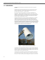
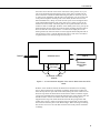
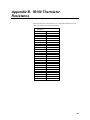
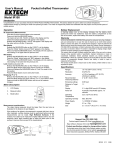
USER MANUAL IR100/IR120 Infra-red Remote Temperature Sensor Issued: 25.2.15 Copyright © 2007-2015 Campbell Scientific Ltd. CSL 708 Guarantee This equipment is guaranteed against defects in materials and workmanship. This guarantee applies for 24 months from date of delivery. We will repair or replace products which prove to be defective during the guarantee period provided they are returned to us prepaid. The guarantee will not apply to: Equipment which has been modified or altered in any way without the written permission of Campbell Scientific Batteries Any product which has been subjected to misuse, neglect, acts of God or damage in transit. Campbell Scientific will return guaranteed equipment by surface carrier prepaid. Campbell Scientific will not reimburse the claimant for costs incurred in removing and/or reinstalling equipment. This guarantee and the Company’s obligation thereunder is in lieu of all other guarantees, expressed or implied, including those of suitability and fitness for a particular purpose. Campbell Scientific is not liable for consequential damage. Please inform us before returning equipment and obtain a Repair Reference Number whether the repair is under guarantee or not. Please state the faults as clearly as possible, and if the product is out of the guarantee period it should be accompanied by a purchase order. Quotations for repairs can be given on request. It is the policy of Campbell Scientific to protect the health of its employees and provide a safe working environment, in support of this policy a “Declaration of Hazardous Material and Decontamination” form will be issued for completion. When returning equipment, the Repair Reference Number must be clearly marked on the outside of the package. Complete the “Declaration of Hazardous Material and Decontamination” form and ensure a completed copy is returned with your goods. Please note your Repair may not be processed if you do not include a copy of this form and Campbell Scientific Ltd reserves the right to return goods at the customers’ expense. Note that goods sent air freight are subject to Customs clearance fees which Campbell Scientific will charge to customers. In many cases, these charges are greater than the cost of the repair. Campbell Scientific Ltd, 80 Hathern Road, Shepshed, Loughborough, LE12 9GX, UK Tel: +44 (0) 1509 601141 Fax: +44 (0) 1509 601091 Email: [email protected] www.campbellsci.co.uk PLEASE READ FIRST About this manual Please note that this manual was originally produced by Campbell Scientific Inc. primarily for the North American market. Some spellings, weights and measures may reflect this origin. Some useful conversion factors: Area: 1 in2 (square inch) = 645 mm2 Length: 1 in. (inch) = 25.4 mm 1 ft (foot) = 304.8 mm 1 yard = 0.914 m 1 mile = 1.609 km Mass: 1 oz. (ounce) = 28.35 g 1 lb (pound weight) = 0.454 kg Pressure: 1 psi (lb/in2) = 68.95 mb Volume: 1 UK pint = 568.3 ml 1 UK gallon = 4.546 litres 1 US gallon = 3.785 litres In addition, while most of the information in the manual is correct for all countries, certain information is specific to the North American market and so may not be applicable to European users. Differences include the U.S standard external power supply details where some information (for example the AC transformer input voltage) will not be applicable for British/European use. Please note, however, that when a power supply adapter is ordered it will be suitable for use in your country. Reference to some radio transmitters, digital cell phones and aerials may also not be applicable according to your locality. Some brackets, shields and enclosure options, including wiring, are not sold as standard items in the European market; in some cases alternatives are offered. Details of the alternatives will be covered in separate manuals. Part numbers prefixed with a “#” symbol are special order parts for use with non-EU variants or for special installations. Please quote the full part number with the # when ordering. Recycling information At the end of this product’s life it should not be put in commercial or domestic refuse but sent for recycling. Any batteries contained within the product or used during the products life should be removed from the product and also be sent to an appropriate recycling facility. Campbell Scientific Ltd can advise on the recycling of the equipment and in some cases arrange collection and the correct disposal of it, although charges may apply for some items or territories. For further advice or support, please contact Campbell Scientific Ltd, or your local agent. Campbell Scientific Ltd, Campbell Park, 80 Hathern Road, Shepshed, Loughborough, LE12 9GX, UK Tel: +44 (0) 1509 601141 Fax: +44 (0) 1509 601091 Email: [email protected] www.campbellsci.co.uk Contents PDF viewers note: These page numbers refer to the printed version of this document. Use the Adobe Acrobat® bookmarks tab for links to specific sections. 1. Introduction.................................................................. 1 2. Specifications .............................................................. 1 2.1 General Specifications .............................................................................. 1 3. Wiring ........................................................................... 2 3.1 Spectral response ...................................................................................... 2 4. Installation.................................................................... 4 5. Principles of Measurement ......................................... 8 5.1 5.2 5.3 5.4 5.5 Thermopile Detector ................................................................................. 8 Thermistor ................................................................................................ 8 The Stefan Boltzmann Law ...................................................................... 8 Correction for Non-Blackbody Surfaces .................................................. 9 Getting the best measurements ............................................................... 10 6. Program Examples & Explanation of Terms .................................................................... 11 6.1 IR100 Blackbody Infrared Temperature Measurement .......................... 11 6.1.1 Thermistor Measurement – Sensor Body Temperature ............... 11 6.1.2 Thermopile Detector – Infrared Radiation Measurement ............ 11 6.2 Correcting for an enclosure window....................................................... 13 6.3 Non-Blackbody Infrared Temperature Measurement ............................. 13 6.4 CRBasic CR1000 Program Examples .................................................... 14 6.4.1 CRBasic example with Emissivity correction ............................. 14 6.4.2 CRBasic example with Emissivity and Window film correction .................................................................................. 15 6.5 Edlog CR10X Program Example............................................................ 16 7. Maintenance ............................................................... 20 i Appendices A Correction for Non-Blackbody used in Campbell Scientific’s Road Temperature Monitoring Equipment ..................................................................... A-1 B IR100 Thermistor resistance ................................... B-1 Table 1. IR100 Datalogger Wiring Details ............................................................... 2 Figures 1. 2. 3. 4. 5. A picture of the IR-SS with IR120 fitted .................................................... 4 A cross-sectional diagram of the sensor fitted inside the IR-SS shield ...... 5 The shield fitted onto the IR1X0 mounting arm ......................................... 6 An IR-SS fitted to a pole with an optional band clamp fitting ................... 6 The arrangement of the nut and washers on the band clamp fitting ........... 7 ii IR100/IR120 Infra-red Remote Temperature Sensor 1. Introduction The IR100/IR120 is an infrared temperature sensor. It offers a non-contact means of measuring the surface temperature of an object by sensing the infrared radiation given off. It can be used in the measurement of leaf, canopy and average surface temperature. Non-contact measurement is often simpler to install, does not influence the target temperature and is an effective means of getting a spatial average temperature. Two variants of the sensor are available, the IR100 has an ultra-narrow field of view whilst the IR120 has a narrow field of view (see specifications below). Throughout the remainder of this manual IR100 is used to represent both versions. 2. Specifications 2.1 General Specifications Field of View (half angle): IR100 4-5° IR120 20° Dimensions: 92 mm long by 28 mm diameter Mounting holes: 2 x 6 mm thread, 5 mm deep (min) Response Time: <1 second to changes in target temperature Target Output Signal: IR100 5 mV per °C IR120 20 mV per °C (difference from sensor body) 1 IR100/IR120 Infra-red Remote Temperature Sensor Signal Offset: Removed by calibration (supplied) Typical Noise Level as measured by a CS datalogger: IR100 0.2°C RMS IR120 0.05°C RMS Calibrated Range: -25°C below body temperature to +25°C above body temperature Operating Range: -25°C to +60°C Accuracy over Calibrated Range: ±0.2°C (against a blackbody source over a 50°C temperature span under laboratory conditions) Current Consumption: 0.4 mA (when excitation applied), 0 mA quiescent Sensor output impedance: 320 Ohms Thermopile Excitation Voltage: +2 to +3.5V Thermistor Excitation Voltage: -2.5V 3. Wiring The IR100 can be used with all Campbell Scientific dataloggers (except CR200) and most other dataloggers that support negative voltage excitations. Wiring colours and connections between the sensor and datalogger are shown in Table 1. Table 1. IR100 Datalogger Wiring Details Colour Description Wiring (SE) Wiring (Diff) Brown Thermistor SE Channel SE Channel Green IR Temperature SE Channel Diff (x) High White Ground / IR Temperature AG Diff (x) Low Red Excitation EX EX Black Ground AG AG Clear Shield The IR100 can be wired either single ended or differentially as detailed in Table 1. 3.1 Spectral response Wavelength Range: See graphs below. 2 IR100: effective bandwidth 7-14 µm (some sensitivity from 2-6 µm) IR120: 8 to 14 µm User Manual Thermistor 30K @25°C Excitation Thermistor Red 30K@ 77020R Brown Ground White Ground Black IR Temp Green Shield Clear Amplifier A m p l i f Thermopile i e r 3 IR100/IR120 Infra-red Remote Temperature Sensor 4. Installation The IR100 sensor should not be allowed to fill with water. Do not point skywards. The IR100 can be secured by means of one or two 6 mm screws to fix the sensor to a flat surface - such as a metal mounting bracket (screws not provided). Older units had a ¼-20 UNC thread. For best precision the body should not be exposed to rapid changes of temperature – ideally shielded from direct exposure to wind, rain, sun and handling. Optional housings are available for these sensors which both protect the sensor from the weather and act to dampen rapid temperature changes, which can improve measurement accuracy. The IR-SS Solar Shield is the simple shield recommended for most outdoor installations. It protects the sensor from direct solar radiation and other weather which might otherwise lead to rapid changes of body temperature which can lead to transient measurement errors. The sensor can be mounted to any suitable structure using the 6 mm threaded hole in the side of the shield for example on Part 009905 the IR1x0 mounting arm, that is designed to attach to Campbell Scientific Instrument tripods and towers. Figure 1 shows an IR120 mounted inside the shield on the end of a 009905 arm. Figure 1. A picture of the IR-SS with IR120 fitted To install the sensor inside the IR-SS shield, two nylon mounting pillars plus 6 mm screws are provided (plus spares). Refer to Figure 2 below. This shows the sensor in place with the mounting holes pointing downwards, which is the normal orientation when installed in the field. To fit the sensor in the shield, lay the main tube of the shield on a desk with the mounting holes facing up. Rotate the sensor so the flat side of the sensor faces up too. Take one of the nylon mounting pillars and place it on the flat of 4 User Manual the sensor above the hole in the sensor nearest the cable (position A) so you can see the mounting hole through the centre of the pillar. Carefully lift the sensor and insert it inside the shield balancing the pillar on sensor as you do so. Move it into alignment with the holes in the shield so you can see the hole in the pillar through the matching hole in the shield (the hole nearest to the metal threaded insert). Drop one of the 20 mm nylon screws through the hole in the shield and through the hole in the pillar. Turn it gently to pick up the thread in the sensor body. Check the pillar is still in place and turn the screw clockwise until it is hand tight. With the sensor held by this screw, pick up the shield and look into the target end. Take the other mounting pillar and slide it down the flat side of the sensor until it is centred on the empty hole in the shield (position B). Insert the other screw through the shield and pillar and on into the sensor. Screw it into the thread in the sensor. Then use a screwdriver to tighten both screws without using excessive force. SENSOR BODY TARGET B MOUNTING PILLARS CABLE A EXTERNAL MOUNTING HOLE EXTERNAL SCREW HEADS Figure 2. A cross-sectional diagram of the sensor fitted inside the IR-SS shield With the sensor inside the shield, the shield can be mounted on a mounting arm or other rigid structure. If possible, mount the shield so the sun does not shine directly into the open ends of the shield, hitting the sensor inside. Do not block the top end of the shield which would restrict natural ventilation. Figure 3 shows the shield fitted onto the IR1X0 mounting arm. Note that the cable ties should be used to restrict movement of the cable. The mounting arm is supplied with a long bolt which should be used with the spring washer and locking nut, as shown. After screwing the bolt into the shield, use the locking nut to lock the shield in place at the desired angle. When inserting a mounting bolt, do not screw it too far such that it hits the sensor body which could lead to damage. 5 IR100/IR120 Infra-red Remote Temperature Sensor Figure 3. The shield fitted onto the IR1X0 mounting arm Optional band-clamp, pole mounts are available to allow the IR-SS to be mounted on the side of lamp posts and similar structures. The band-clamps are specified to match a specific range of size of pole. Figure 4. An IR-SS fitted to a pole with an optional band clamp fitting For this type of bracket the shield must first be attached to the band-clamp bracket. This is most easily done before mounting the bracket on the pole. To do this first put the nut, then the two washers onto the bolt of the bracket, screwing the nut loosely up to the bracket and leaving the thread of the bolt 6 User Manual free at the end. Then screw that bolt into the side of the shield, so the bolt is fully screwed into the metal insert in the shield, but not so far that the end is not touching the body of the sensor. Now mount the bracket on the pole using the band, rotating the band so the sensor points in the right direction. Next rotate the sensor on the bolt to point at the target and use the lock nut on the bolt to fix the shield at the correct angle. Tighten the bolt so the spring washer is compressed. Do not overtighten as you risk turning the fitting in the plastic shield. The arrangement of the nut and washer are shown below in Figure 5. Figure 5. The arrangement of the nut and washers on the band clamp fitting After mounting the sensor, tie the cable to the pole to stop it flexing in the wind. When installing the sensor, consideration must be taken of the field of view, distance to the target and angle of the sensor relative to the main surfaces of the target. All of these can affect the accuracy of the measurement. The field of view can be calculated thus: with a half angle of n degrees (see specifications) the sensor will observe radiation from a circular area whose radius will be = tan(n) * the target distance from sensor. If possible, the distance to the target should be minimised as visible (mist) and invisible water vapour or dust in the air between the sensor and target can lead to measurement errors. The shorter the distance the smaller this effect. It is also desirable for the sensor to point at the surface being measured directly (at 90 degrees relative to the surface) rather than being at an acute angle. This is because many surfaces will have increased reflectivity at low angles of view. At acute angles the sensor reading may end up being biased towards the temperature of the reflections rather than the target itself. (This is similar to trying to look into a pond where you cannot see the bottom of the pond, only a reflection at low angles of view.) 7 IR100/IR120 Infra-red Remote Temperature Sensor Both variants of these sensors limit sensitivity to just the long wave, infra-red spectrum as required for infra-red thermometry. The IR100, has some residual sensitivity to radiation below 7 µm so care should be taken with that model in particular to make sure shorter wavelength radiation, such as that from the sun, does not reflect off surfaces with high albedo into the sensor. The IR100 will also be more sensitive to moisture in the atmosphere compared to the IR120 so the distance to the target should be minimised. Beware that other housings which have a front window do reduce the sensor output and accuracy a little as a result of corrections and assumptions that need to be made to correct the readings of the sensor due to it looking through a window (see Appendix A and Section 6.2). 5. Principles of Measurement 5.1 Thermopile Detector The IR100 sensor contains a thermopile which detects the presence of thermal radiation. This consists of a number of thermocouples connected in series, one set being exposed to the source radiation, whilst the other is shielded from it. A highly polished metal cone concentrates the radiation onto the exposed junctions, which are coated with lamp-black to enhance the efficiency with which the radiation is absorbed. The thermopile detector outputs a voltage proportional to the thermal energy balance between itself and the surface it is detecting. A separate thermistor, embedded in the sensor body directly behind the thermopile measures the reference body temperature. Both results are combined and processed in the logger to output the measured surface temperature. 5.2 Thermistor The measured resistance of the thermistor varies with temperature using a third order Steinhart-Hart thermistor equation. 1 A B(ln(R)) C(ln(R)) 3 T where A, B and C are calibrated constants for individual thermistors. The sensor element used in the IR100 is individually calibrated and so the Steinhart-Hart must be applied in the program using the sensor calibration coefficients supplied. 5.3 The Stefan Boltzmann Law Using the Stefan-Boltzmann Law, we can determine the temperature of a particular surface based on the amount of thermal energy it radiates. Stefan-Boltzmann states that the total energy radiated per unit time per unit surface area of a blackbody is proportional to the fourth power of the temperature of the body expressed in Kelvin’s, i.e. E = σT4 8 User Manual where σ is a constant of proportionality known as Stefan’s constant, whose value is 5.67E-8 W m-2 K-4. The rate at which a unit surface area of this blackbody receives radiation from surrounding objects at temperature T is σT4, and the rate at which the blackbody at temperature T0 emits radiation in σT04, thus the net rate of loss of energy by the blackbody is therefore given by Enet, where Enet = σ(T4 – T04) Thus: E 4 T 4 net T0 σ where T4 is the surface temperature observed by the detector and T04 the temperature of the detector measured by an internal thermistor. Enet is determined by the amplified thermocouple voltage inserted into a polynomial equation, whose constants were obtained during calibration from a 2nd order polynomial fit of sensor voltage and irradiance obtained during calibration. The specifications of the thermopile sensor state that the sensitivity decreases by 0.04% per deg C. To compensate for this we need to increase the multiplication factor by 0.04% for every degree C above the calibration temperature. The following equation takes care of this compensation: Temperature_Compensated_x = x * 1.0004 (IRcan_Temp -25) 5.4 Correction for Non-Blackbody Surfaces The IR100 sensor is calibrated against a blackbody target. The proportion of energy it emits to that which it reflects is known as its Emissivity (ε). A black body is said to have an emissivity of 1. In the real environment most surfaces will reflect some radiation from the surroundings and this component should be removed to get an accurate reading. Since: E T 4 And: Emeasured Esurface (1 ) Ereflected Tmeasured (1 )Treflected 4 Thus: 4 surface T 4 Where ε is the emissivity of the surface whose value depends on the nature of the surface and always lies between 0 and 1 and Treflected is the temperature of the surrounding surfaces whose energy is, in part, being reflected by the measured surface. For most applications it is commonly assumed that reflected radiation comes from surfaces at the sensor body temperature. However, in outdoor applications it may be better to use a more appropriate temperature e.g. air temperature. The algorithms used within Campbell Scientific’s road temperature monitoring equipment take account of reflected radiation from the sky, building and trees in the surrounding area and radiation emitting from the environmental film that 9 IR100/IR120 Infra-red Remote Temperature Sensor protects the sensor. All the algorithms consist of converting the temperatures, assumed or measured, into their fourth power in Kelvin, and subtracting portions one from the other to arrive at the actual surface temperature. Please refer to Section 6.2 and Appendix A for a more detailed explanation. 5.5 Getting the best measurements Taking good infra-red temperature measurements does require some understanding of the measurement principle and careful use of the sensor, especially for field measurements. Here are some points you need to take into consideration: 10 The accuracy of the temperature measurement is dependent on knowing the emissivity of the surface being measured. The further the emissivity is from one the more critical it is to measure and compensate for the emissivity. Try to take measurements with the sensor pointed directly at the target rather than at acute angles. This is because reflection can lead to significant errors and reflection increases the more acute the angle. Those reflections can be long wave IR and/or from reflected sunlight (the IR100 is more prone to this as it has a little sensitivity at lower wavelengths). Try to install the sensor relatively close to the surface being measured (within a few metres) as mist and even high humidity (especially in the case of the IR100) will cause the sensor to be influenced by the temperature of the air between it and the target. On the other hand do not install the sensor so close that it interferes with the IR exchange with the target and its environment. Try to ensure the sensor body is insulated from rapid changes in temperature, as small gradients of temperature around the sensor aperture can lead to large transient measurement errors. To do this, if the sensor is installed outside, the sensor should be shielded from direct exposure to the sun, which could be in the form of a shield or added insulation (a tube of foam pipe insulation is suitable). Alternatively, it can be installed in an optional camera style housing with an IR transmissive window. If your readings seem to be always close to the body, i.e. not sensing the target temperature as expected, check the sensing aperture of the sensor is not blocked (by spiders etc) and if using an enclosure that the IR transmissive film is not dirty or wet. User Manual 6. Program Examples & Explanation of Terms 6.1 IR100 Blackbody Infrared Temperature Measurement 6.1.1 Thermistor Measurement - Sensor Body Temperature The following CR1000 example shows the code required to obtain the sensor body temperature measurement from the thermistor in the IR100 sensor. A 20 ms delay is used to allow adequate settling time for long cable runs. BRHalf(IRSensor_can,1,mV2500,3,Vx1,1, -2500,false,20000,_50Hz,1,0) IRSensor_resis=77020*(IRSensor_can/(1-IRSensor_can)) IRSensorcan_temp=1/(IRSensor_a + IRSensor_b*LN(IRSensor_resis) + IRSensor_c *(LN(IRSensor_resis))^3) - 273.15 A half-bridge measurement is taken to obtain the ratio of the measured voltage divided by the excitation voltage, from which the resistance is then calculated. This resistance is then entered into the Steinhart-Hart equation together with the calibration constants (IRSensor_a, IRSensor_b and IRSensor_c) obtained during the body temperature calibration and supplied with the sensor. Each sensor is individually calibrated to return a value in degrees KELVIN. Note the use of a negative excitation voltage. This is used because the same wire is used to power the Thermopile amplifier (see next section) by applying a positive voltage. 6.1.2 Thermopile Detector - Infrared Radiation Measurement The following CR1000 program example shows the code required to obtain a raw infrared radiation measurement from the IR-100 sensor. To minimise the effect of noise on the signal the IR100 has an internal amplifier that requires a positive 2500 mV excitation and at least a75 mS settling time before taking the measurement. You need to choose whether to make the measurement differentially or singleended. A differential measurement will give the most accurate reading, especially for long cable runs, but needs a differential channel – equivalent to two singleended inputs. Therefore the single-ended technique is only usually used if there is a shortage of inputs on the datalogger and cables are short (<10 m). Refer to Table 1, above, for the difference in wiring. The program structure is: 'Single ended measurement - note the positive 2500mV 'excitation which is turned on first to force a 75mS delay ExciteV(Vx1,2500,0) Delay(0,75,mSec) BrHalf(IRSensor_Volt,1,mV250,1,Vx1,1,2500,False,0,_50Hz,2500,0) Or: 'Differential measurement - note the positive 2500mV 'excitation which is turned on first to force a 75mS delay ExciteV(Vx1,2500,0) Delay(0,75,mSec) BrFull(IRSensor_Volt,1,mV250,1,Vx1,1,2500,False,False,0,_50Hz,2.5,0) 11 IR100/IR120 Infra-red Remote Temperature Sensor Then: 'Apply temperature compensation for the IR Sensor IRSensor_Volt_TC = IRSensor_Volt * 1.0004 ^(IRSensorCan_Temp - 25) ‘Apply calibration factors IRSensor_E=IRSensor_x*IRSensor_Volt_TC^2+IRSensor_y*IRSensor_Volt_TC+IRSensor_z NOTE The range codes will need to be amended if using a CR3000 datalogger. The bridge instructions have multipliers in them to scale the values back to mV. IRSensor_E is the resultant measured thermal radiation proportional to the net rate of energy exchange with the target surface. and must be combined using Stefan Boltzmann with the radiant energy from the sensor to obtain the measured remote temperature. IRSensor_T4=(IRSensor_E/5.67E8)+(IRSensorcan_temp+273.15)^4 IRSensor_T=IRSensor_T4^0.25-273.15 If the target surface were a blackbody, then this would suffice and the temperature value obtained would be an accurate representation of actual surface temperature. However, since nothing in the real environment acts like a blackbody, we have to correct this temperature value to account for the emissivity of the target surface. Additionally if the sensor is looking through a window from inside an enclosure an additional correction is needed. 6.2 Correcting for an enclosure window The following example shows the additional lines of code required to obtain an infrared temperature measurement from the IR100 sensor, when installed inside an enclosure that has protective window. This correction is not needed for the sensor fitted in an IR-SS shield. Campbell Scientific uses a thin plastic film that has high IR transmission. The signal the sensor sees is mainly from the target but partly (about 20%) from the window material. To correct for this the window temperature has to be known and the IR transmission of the window material. A similar equation is used as for emissivity corrections to separate out energy coming from the target. 'Film IR transmission – CSL window - measured value Const Film = 0.79 'The correction equation IRTFilm_T4 = ((IRSensor_T4 - ((Airtemp + 273.15)^4 * (1 - Film))) / Film) The line above uses air temperature as a measure of the window temperature which is a fair assumption as long as the window is shaded from the sun. If air temperature is not available the sensor body temperature can be used, although this may result in small transient errors due to the different time responses of the window and the sensor body. The variable IRTFilm_T4 is the corrected target temperature in Kelvin to the power four. It can be converted to Celsius or used in place of IRSensor_T4 in the emissivity correction equation shown in Section 6.3 12 User Manual 6.3 Non-Blackbody Infrared Temperature Measurement The following example shows the additional line of code required to obtain an infrared temperature measurement from the IR100 sensor, corrected for a target surface emissivity of 0.94. and assuming that the adjacent surfaces are at the sensor temperature: Emissivity = 0.94 Temp=((IRSensor_T4-((IRSensorcan_temp+273.15)^4*(1Emissivity)))/Emissivity)^0.25-273.15 When measuring surface leaf temperature under a tree canopy, a measure of air temperature may be more suitable for the adjacent temperature than the sensor can temperature. See Appendix A for further examples. 13 IR100/IR120 Infra-red Remote Temperature Sensor 6.4 CRBasic CR1000 Program Examples 6.4.1 CRBasic example with Emissivity correction 'CR1000 Program for the IR1x0 with emissivity correction 'Calibration Data for the IR1x0 'NOTE : These values should match those listed on the IR100 calibration certificate Const Coeff_A = 9.355652E-04 Const Coeff_B = 2.203275E-04 Const Coeff_C = 1.394681E-07 Const Coeff_X = 2.748588E-04 Const Coeff_Y = 1.787100E+00 Const Coeff_Z = 6.923498E-02 'Emissivity should be appropriate for the surface type Const Emissivity = 0.94 Dim BR_Res Dim IRSensor_Resis Public IRSensorCan_Temp Public Airtemp Dim IRSensor_Volt Dim IRSensor_Volt_TC Dim IRSensor_E Dim IRSensor_T4 Dim IRSensor_T Public IRTemp_C 'The Measured Bridge Resistance 'Thermistor Resistance 'Thermistor Temperature in Celsius 'Used in the emissivity correction - ideally measured 'with another sensor. 'The Measured Thermopile Voltage 'The Measured Thermopile Voltage – Temp Compensated 'Energy Difference 'Black body surface temperature to the power 4 'Black body surface temperature in Kelvin - Uncorrected 'Corrected Surface Temperature in Celsius DataTable(IR100Data,1,-1) DataInterval(0,1,Min,10) Average(1,IRTemp_C,FP2,False) : FieldNames("AVG_Surface_Temperature_C") EndTable 'Main Program BeginProg Scan (5,Sec,0,0) 'Measure the IR1x0 Body Temperature '---------------------------------'Measure the thermistor using a half bridge by applying a negative 'excitation voltage of -2.5V 'Note that switching the bridge excitation is set to FALSE. 'Uses channel 3 Single-ended. 20 ms settling time for long cable BrHalf(BR_Res,1,mV2500,3,Vx1,1,-2500,False,20000,_50Hz,1,0) 'Multiply the ratio of measured voltage by a constant appropriate to the 'thermistor IRSensor_Resis = 77020 * (BR_Res / (1 - BR_Res)) 'Using Steinhart-hart, apply the calibration coefficients to arrive at a 'body temperature in Celsius IRSensorCan_Temp = 1 / (Coeff_A + Coeff_B * LN(IRSensor_Resis) + Coeff_C * (LN(IRSensor_Resis))^3) - 273.15 'Measure the IR1x0 Infrared Temperature '-------------------------------------'Measure the infrared temperature using a full bridge instruction 'Note that switching the bridge excitation is set to FALSE. 'Use 75 ms settling time, to allow amplified signal to settle 'The multiplier is used to correct the ratiometric output to mV 'Uses channel 1 differential. ExciteV(Vx1,2500,0) Delay(0,75,mSec) BrFull(IRSensor_Volt,1,mV250,1,Vx1,1,2500,False,False,0,_50Hz,2.5,0) 'Apply temperature compensation IRSensor_Volt_TC = IRSensor_Volt * 1.0004 ^(IRSensorCan_Temp - 25) 'Apply coefficients 14 User Manual IRSensor_E = Coeff_X * IRSensor_Volt_TC^2 + Coeff_Y * IRSensor_Volt_TC + Coeff_Z 'Add difference to absolute energy from the sensor body IRSensor_T4 = (IRSensor_E / 5.67E-8) + ((IRSensorCan_Temp + 273.15)^4) 'Resolve for remote surface temperature in Kelvin – ‘NOTE this is the 'UNCORRECTED value IRSensor_T = (IRSensor_T4^0.25) - 273.15 'Combine with the correction for Emissivity and Convert to Celsius 'Have to assume Airtemp = IRsensorcan_temp in this example as no air temp 'measurement Airtemp=IRSensorCan_Temp IRTemp_C = ((IRsensor_T4-((Airtemp + 273.15)^4* (1-Emissivity)))/Emissivity)^0.25 - 273.15 'Store the results to a table. CallTable(IR100Data) NextScan EndProg 6.4.2 CRBasic example with Emissivity and Window film correction 'CR1000 Program for the IR1x0 with film correction 'Used when the sensor is installed inside a protective housing with a 'transmissive film or window 'Calibration Data for the IR1x0 'NOTE : These values should match those listed on the IR100 calibration certificate Const Coeff_A = 9.355652E-04 Const Coeff_B = 2.203275E-04 Const Coeff_C = 1.394681E-07 Const Coeff_X = 2.748588E-04 Const Coeff_Y = 1.787100E+00 Const Coeff_Z = 6.923498E-02 'Emissivity should be appropriate for the surface type Const Emissivity = 0.94 'Film IR transmission - CSL measured value Const Film = 0.79 Dim BR_Res Dim IRSensor_Resis Public IRSensorCan_Temp Public Airtemp Dim IRSensor_Volt Dim IRSensor_Volt_TC Dim IRSensor_E Dim IRSensor_T4 Dim IRSensor_T Dim IRTFilm_T4 Public IRTemp_C 'The Measured Bridge Resistance 'Thermistor Resistance 'Thermistor Temperature in Celsius 'Used in the emissivity correction - ideally measured 'with another sensor. 'The Measured Thermopile Voltage 'The Measured Thermopile Voltage – Temp Compensated 'Energy Difference 'Black body surface temperature to the power 4 'Black body surface temperature in Kelvin – Uncorrected 'Temperature after the film correction to the power 4 'Corrected Surface Temperature in Celsius DataTable(IR100Data,1,-1) DataInterval(0,1,Min,10) Average(1,IRTemp_C,FP2,False) : FieldNames("AVG_Surface_Temperature_C") EndTable 'Main Program BeginProg Scan (5,Sec,0,0) 'Measure the IR1x0 Body Temperature '---------------------------------'Measure the thermistor using a half bridge by applying a negative 'excitation voltage of -2.5V 'Note that switching the bridge excitation is set to FALSE. 15 IR100/IR120 Infra-red Remote Temperature Sensor 'Uses channel 3 Single-ended. 20 ms settling time for long cable BrHalf(BR_Res,1,mV2500,3,Vx1,1,-2500,False,20000,_50Hz,1,0) 'Multiply the ratio of measured voltage by a constant appropriate to the 'thermistor IRSensor_Resis = 77020 * (BR_Res / (1 - BR_Res)) 'Using Steinhart-hart, apply the calibration coefficients to arrive at a 'body temperature in Celsius IRSensorCan_Temp = 1 / (Coeff_A + Coeff_B * LN(IRSensor_Resis) + Coeff_C * (LN(IRSensor_Resis))^3) 273.15 'Measure the IR1x0 Infrared Temperature '-------------------------------------'Measure the infrared temperature using a full bridge instruction 'Note that switching the bridge excitation is set to FALSE. 'Use 75 ms settling time, to allow amplified signal to settle 'The multiplier is used to correct the ratiometric output to mV 'Uses channel 1 differential. ExciteV(Vx1,2500,0) Delay(0,75,mSec) BrFull(IRSensor_Volt,1,mV250,1,Vx1,1,2500,False,False,0,_50Hz,2.5,0) 'Apply temperature compensation IRSensor_Volt_TC = IRSensor_Volt * 1.0004 ^(IRSensorCan_Temp - 25) 'Apply coefficients IRSensor_E = Coeff_X * IRSensor_Volt_TC^2 + Coeff_Y * IRSensor_Volt_TC + Coeff_Z 'Add difference to absolute energy from the sensor body IRSensor_T4 = (IRSensor_E / 5.67E-8) + ((IRSensorCan_Temp + 273.15)^4) 'Resolve for remote surface temperature in Kelvin – 'NOTE this is the 'UNCORRECTED value IRSensor_T = (IRSensor_T4^0.25) - 273.15 'Correct for the effects of the high infrared transmission film 'Have to assume Airtemp = IRsensorcan_temp in this example as no air temp 'measurement Airtemp=IRSensorCan_Temp IRTFilm_T4 = ((IRSensor_T4 - ((Airtemp + 273.15)^4 * (1 - Film))) / Film) 'Combine with the correction for Emissivity and Convert to Celsius IRTemp_C = ((IRTFilm_T4-((Airtemp + 273.15)^4* (1-Emissivity)))/Emissivity)^0.25 - 273.15 'Store the results to a table. CallTable(IR100Data) NextScan EndProg 6.5 Edlog CR10X Program Example This example does not include a correction of any enclosure window film. ;{CR10X} ;IR120 Example Program ; *Table 1 Program 01: 5 Execution Interval (seconds) ; Calibration Data for the IR120 ; NOTE : These values should match those listed on the IR100 Calibration Certificate 1: Z=F x 10^n (P30) 1: 2.29176 F 2: -5 n, Exponent of 10 3: 4 Z Loc [ Coeff_X ] 16 User Manual 2: 1: 2: 3: Z=F x 10^n (P30) 5.17221 F -1 n, Exponent of 10 5 Z Loc [ Coeff_Y ] 3: 1: 2: 3: Z=F x 10^n (P30) -3.50399 F 0 n, Exponent of 10 6 Z Loc [ Coeff_Z ] 4: 1: 2: 3: Z=F x 10^n (P30) 0.94 F 00 n, Exponent of 10 18 Z Loc [ Emissiv ] ; Measure the IR100 Body Temperature ;----------------------------------; Measure the thermistor using half bridge by applying negative excitation voltage of -2.5V 5: Excite-Delay (SE) (P4) 1: 1 Reps 2: 5 2500 mV Slow Range 3: 3 SE Channel 4: 1 Excite all reps w/Exchan 1 5: 2 Delay (0.01 sec units) 6: -2500 mV Excitation 7: 7 Loc [ BR_Res ] 8: -.0004 Multiplier ; -1/2500 to give the ratio V/Vx 9: 0.0 Offset ; Multiply the ratio of measured voltage by constant appropriate to thermistor 6: BR Transform Rf[X/(1-X)] (P59) 1: 1 Reps 2: 7 Loc [ BR_Res ] 3: 77020 Multiplier (Rf) ;Use Steinhart-Hart, apply calibration coeff to get body temperature in deg C ; Calibration Data for the IR120 ; NOTE : These values should match those listed on the IR100 Calibration Certificate 7: Steinhart-Hart Equation (P200) 1: 1 Reps 2: 7 Source Loc (R)(Ohms) [ BR_Res ] 3: 8 Destination Loc (Deg C) [ IR_Can ] 4: 3.08524 A 5: -3 x 10^n 6: -9.95376 B 7: -5 x 10^n 8: 1.18779 C 9: -6 x 10^n ; Measure the IR100 Infrared Temperature ;--------------------------------------; Measure the infrared temperature using a full bridge Ex-Delay-Diff Volt instruction ; Delay of 80ms for settling time 8: Ex-Del-Diff (P8) 1: 1 Reps 2: 5 2500 mV Slow Range 3: 1 DIFF Channel 4: 1 Excite all reps w/Exchan 1 5: 8 Delay (0.01 sec units) 6: 2500 mV Excitation 7: 12 Loc [ IRs_V ] 8: 1.0 Multiplier 17 IR100/IR120 Infra-red Remote Temperature Sensor 9: 0.0 Offset ; Apply Temperature Compensation 9: Z=X+F (P34) 1: 8 X Loc [ IR_Can ] 2: -25 F 3: 10 Z Loc [ IR_Can_Tp ] 10: Z=F x 10^n (P30) 1: 1.0004 F 2: 00 n, Exponent of 10 3: 11 Z Loc [ IRs_V_TC ] 11: Z=X^Y (P47) 1: 11 X Loc [ IRs_V_TC ] 2: 10 Y Loc [ IR_Can_Tp ] 3: 11 Z Loc [ IRs_V_TC ] 12: Z=X*Y (P36) 1: 12 X Loc [ IRs_V 2: 11 Y Loc [ IRs_V_TC 3: 11 Z Loc [ IRs_V_TC ] ] ] ; Apply Coefficients 13: Z=X*Y (P36) 1: 11 X Loc [ IRs_V_TC 2: 11 Y Loc [ IRs_V_TC 3: 13 Z Loc [ IRs_E ] ] ] 14: Z=X*Y (P36) 1: 4 X Loc [ Coeff_X 2: 13 Y Loc [ IRs_E 3: 13 Z Loc [ IRs_E ] ] ] 15: Z=X*Y (P36) 1: 5 X Loc [ Coeff_Y 2: 11 Y Loc [ IRs_V_TC 3: 14 Z Loc [ IRs_Temp ] ] ] 16: Z=X+Y (P33) 1: 14 X Loc [ IRs_Temp 2: 6 Y Loc [ Coeff_Z 3: 14 Z Loc [ IRs_Temp ] ] ] 17: Z=X+Y (P33) 1: 13 X Loc [ IRs_E 2: 14 Y Loc [ IRs_Temp 3: 13 Z Loc [ IRs_E ] ] ] ; Add difference to absolute energy from sensor body 18: Z=X+F (P34) 1: 8 X Loc [ IR_Can ] 2: 273.15 F 3: 14 Z Loc [ IRs_Temp ] 19: Z=F x 10^n (P30) 1: 4 F 2: 00 n, Exponent of 10 3: 15 Z Loc [ IR_Exp ] 20: Z=X^Y (P47) 1: 14 X Loc [ IRs_Temp 2: 15 Y Loc [ IR_Exp 3: 14 Z Loc [ IRs_Temp 18 ] ] ] User Manual 21: Z=F x 10^n (P30) 1: 5.67 F 2: -8 n, Exponent of 10 3: 15 Z Loc [ IR_Exp ] 22: Z=X/Y (P38) 1: 13 X Loc [ IRs_E 2: 15 Y Loc [ IR_Exp 3: 13 Z Loc [ IRs_E ] ] ] 23: Z=X+Y (P33) 1: 13 X Loc [ IRs_E 2: 14 Y Loc [ IRs_Temp 3: 16 Z Loc [ IRs_T4 ] ] ] ; Resolve for remote surface temp in Kelvin 24: Z=F x 10^n (P30) 1: 0.25 F 2: 00 n, Exponent of 10 3: 15 Z Loc [ IR_Exp ] 25: Z=X^Y (P47) 1: 16 X Loc [ IRs_T4 2: 15 Y Loc [ IR_Exp 3: 17 Z Loc [ IRs_T 26: Z=X+F (P34) 1: 17 X Loc [ IRs_T 2: -273.15 F 3: 17 Z Loc [ IRs_T ] ] ] ] ] ; Correction for Emissivity and convert to deg C 27: Z=F x 10^n (P30) 1: 4 F 2: 00 n, Exponent of 10 3: 15 Z Loc [ IR_Exp ] 28: Z=X+F (P34) 1: 8 X Loc [ IR_Can 2: 273.15 F 3: 14 Z Loc [ IRs_Temp 29: Z=X^Y (P47) 1: 14 X Loc [ IRs_Temp 2: 15 Y Loc [ IR_Exp 3: 14 Z Loc [ IRs_Temp ] ] ] ] ] 30: Z=X*F (P37) 1: 18 X Loc [ Emissiv ] 2: -1 F 3: 19 Z Loc [ EmissivTp ] 31: Z=X+F (P34) 1: 19 X Loc [ EmissivTp ] 2: 1 F 3: 19 Z Loc [ EmissivTp ] 32: Z=X*Y (P36) 1: 14 X Loc [ IRs_Temp ] 2: 19 Y Loc [ EmissivTp ] 3: 14 Z Loc [ IRs_Temp ] 33: Z=X-Y (P35) 1: 16 X Loc [ IRs_T4 2: 14 Y Loc [ IRs_Temp ] ] 19 IR100/IR120 Infra-red Remote Temperature Sensor 3: 14 Z Loc [ IRs_Temp ] 34: Z=X/Y (P38) 1: 14 X Loc [ IRs_Temp 2: 18 Y Loc [ Emissiv 3: 14 Z Loc [ IRs_Temp ] ] ] 35: Z=F x 10^n (P30) 1: 0.25 F 2: 00 n, Exponent of 10 3: 15 Z Loc [ IR_Exp ] 36: Z=X^Y (P47) 1: 14 X Loc [ IRs_Temp 2: 15 Y Loc [ IR_Exp 3: 14 Z Loc [ IRs_Temp ] ] ] 37: Z=X+F (P34) 1: 14 X Loc [ IRs_Temp 2: -273.15 F 3: 20 Z Loc [ IRTemp_C ] ] ; Output array 38: If time is (P92) 1: 0 Minutes (Seconds --) into a 2: 1 Interval (same units as above) 3: 10 Set Output Flag High (Flag 0) 39: Set Active Storage Area (P80) 1: 1 Final Storage Area 1 2: 1 Array ID 40: Average (P71) 1: 1 Reps 2: 20 Loc [ IRTemp_C ] 41: Sample (P70) 1: 1 Reps 2: 20 Loc [ IRTemp_C ] 7. Maintenance The sensor contains no serviceable parts. When installed outside in the field though, the sensor should be checked and cleaned to remove dirt or insects especially within the tube at the free end of the sensor. To clean, use an air duster and if absolutely necessary, due to deposits on the window of the detector, a `cotton bud’ dipped in electronics grade alcohol. Avoid scratching the silvered window. 20 Appendix A. Correction for NonBlackbody used in Campbell Scientific’s Road Temperature Monitoring Equipment This appendix is added so that those wishing to understand the correction method used in IRIS and other road surface monitoring equipment may do so and to help those wishing to apply similar techniques to other applications. The radiation balance model that exists on roads is as follows: The primary components of the observed radiation are thus reflected radiation from the sky and surrounds, radiation emitted by the environmental protective film and the component we are interested in - radiation from the road. Thus: RadObserved = A(RadFilm) + B(RadRoad) + C(RadSky) + D(RadBuildings&trees) Since Radiation Energy = σT4 where T is in Kelvin then rearranging and cancelling out the Stephan Boltzman constant we can say that: TRoad4 = ((TObserved4) - A(TFilm4) - C(TSky4) - D(TBuildings&trees4))/B The proportion of radiation being transmitted through the radiation film is known as the Transmissivity. Thus A = (1-Transmissivity) The proportion of the observed radiation being emitted by the road is dependent on both the Emissivity of the road surface and the Transmissivity of the film. A-1 Thus: B = Transmissivity x Emissivity The proportion or the sky depends to an extent on the exposure to of the site in question. This is known as the Sky View Factor and is the ratio of the area of the surrounding buildings & trees (weighted according to the cosine of their incidence to the surface) to the area of exposed sky. An open road, fully exposed, has a Sky View Factor of 1. A road fully enclosed in a tree canopy may have a Sky View Factor as low as 0. It should be borne in mind that whatever the Sky View Factor may be, only a portion of the radiation coming from the sky will be reflected by the road (1Emissivity) and only a portion of the resulting reflected radiation will be transmitted through the film (Transmissivity) thus: C = (Transmissivity) x (1-Emissivity) x SVF And likewise for the surroundings: D = (Transmissivity) x (1-Emissivity) x (1-SVF) And since the surrounding buildings and trees along with the protective environmental film are all at air temperature we can say that: TFilm4 = TBuildings&trees4 = TAir4 Thus: TRoad4 = ((TObserved4) - C(TSky4) - (TAir4)(A+D))/B Where A = (1-Transmissivity) B = Transmissivity x Emissivity C = Transmissivity x (1-Emissivity) x SVF D = Transmissivity x (1-Emissivity) x (1-SVF) This is a blank page. A-2 Appendix B. IR100 Thermistor Resistance Please note tolerance on these figures is ±5%. Individual calibration for each sensor is included on the calibration certificate. Degree C -25 -20 -15 -10 -5 0 5 10 15 20 25 30 35 40 45 50 55 60 65 70 75 80 85 90 95 100 105 Ohms 363,300.0 273,420.0 207,600.0 158,910.0 122,580.0 95,355.0 74,655.0 58,857.0 46,716.0 37,320.0 30,000.0 24,261.0 19,734.0 16,140.0 13,272.0 10,971.0 9,114.0 7,605.0 6,378.0 5,372.4 4,544.4 3,860.4 3,292.2 2,818.8 2,422.2 2,089.2 1,808.1 This is a blank page. B-1 CAMPBELL SCIENTIFIC COMPANIES Campbell Scientific, Inc. (CSI) 815 West 1800 North Logan, Utah 84321 UNITED STATES www.campbellsci.com [email protected] Campbell Scientific Africa Pty. Ltd. (CSAf) PO Box 2450 Somerset West 7129 SOUTH AFRICA www.csafrica.co.za [email protected] Campbell Scientific Australia Pty. Ltd. (CSA) PO Box 8108 Garbutt Post Shop QLD 4814 AUSTRALIA www.campbellsci.com.au [email protected] Campbell Scientific do Brazil Ltda. (CSB) Rua Apinagés, nbr. 2018 - Perdizes CEP: 01258-00 São Paulo SP BRAZIL www.campbellsci.com.br [email protected] Campbell Scientific Canada Corp. (CSC) 14532 – 131 Avenue NW Edmonton, Alberta T5L 4X4 CANADA www.campbellsci.ca [email protected] Campbell Scientific Centro Caribe S.A. (CSCC) 300N Cementerio, Edificio Breller Santo Domingo, Heredia 40305 COSTA RICA www.campbellsci.cc [email protected] Campbell Scientific Ltd. (CSL) 80 Hathern Road, Shepshed, Loughborough LE12 9GX UNITED KINGDOM www.campbellsci.co.uk [email protected] Campbell Scientific Ltd. (France) 3 Avenue de la Division Leclerc 92160 ANTONY FRANCE www.campbellsci.fr [email protected] Campbell Scientific Spain, S. L. Avda. Pompeu Fabra 7-9 Local 1 - 08024 BARCELONA SPAIN www.campbellsci.es [email protected] Campbell Scientific Ltd. (Germany) Fahrenheitstrasse13, D-28359 Bremen GERMANY www.campbellsci.de [email protected] Campbell Scientific (Beijing) Co., Ltd. 8B16, Floor 8 Tower B, Hanwei Plaza 7 Guanghua Road, Chaoyang, Beijing 100004 P.R. CHINA www.campbellsci.com [email protected] Please visit www.campbellsci.com to obtain contact information for your local US or International representative.