1
1ll
I
Auro ra
Tech nolo gies
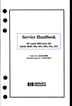
Multipart Model 800
User Manual
For the Sun386i
SunOS 4.0.1
Aurora Technolo gies
One Kendall Square
Suite 2200
Cambridge, MA 02139
(617) 577-128 8
Fax (617) 577-1209
'
Part No: 11 002-1234
Revision D, January 1989
5/JJ : \\lOS- 2.o3o-
\C:S%
1ll
I
AURORA TECHNOLOGIES LICENSE AGREEMENT
This legal document is an agreement between you, the end user, and Aurora Technologies. BY
OPENING THIS DISK PACKAGE, YOU ARE AGREEING TO BECOME BOUND BY THE TERMS OF THIS
AGREEMENT, WHICH INCLUDES THE SOFTWARE LICENSE, AND WARRANTY (collectively the
"Agreement").
THIS AGREEMENT CONSTITUTES THE COMPLETE AGREEMENT BETWEEN YOU AND AURORA
TECHNOLOGIES. IF YOU DO NOT AGREE TO THE TERMS OF THIS AGREEMENT, DO NOT OPEN THE
DISK PACKAGE. PROMPTLY RETURN THE UPOPENED DISK PACKAGE, HARDWARE AND THE
OTHER ITEMS, (INCLUDING WRITTEN MATERIALS, BINDERS OR OTHER CONTAINERS) THAT ARE
PART OF THIS PRODUCT TO AURORA TECHNOLOGIES FOR A FULL REFUND.
AURORA TECHNOLOGIES SOFTWARE LICENSE
1. GRANT OF LICENSE. In consideration of payment of the LICENSE fee, which is a part
of the price that you paid for this product, Aurora Technologies, as Licensor, grants to you the
LICENSEE, a nonexclusive right to use and display this copy of an Aurora Technolgies software
program, (hereinafter the "SOFTWARE") on a single COMPUTER (i.e., with a single CPU) at a
single location. If the single computer on which you use the SOFTWARE is a multiuser system,
the license covers all users on that single system. Aurora Technologies reserves all rights not
expressly granted to LICENSEE.
2. DELIVERY, INSTALLATION, ACCEPTANCE AND RISK OF LOSS. Aurora Technologies
shall deliver the SOFTWARE to a common carrier, F.O.B. Aurora Technolgies fac111ties.
LICENSEE assumes all risk of loss or damage upon delivery of the SOFTWARE by Aurora
Technologies to a common carrier. LICENSEE agrees that acceptance shall occur upon delivery of
the SOFTWARE by Aurora Technologies to LICENSEE or a common carrier. LICENSEE shall be
solely responsilbe for installation of the SOFTWARE on the the computer.
3. PAYMENTS. In consideration of the license and rights in the SOFTWARE granted by
Aurora and in consideration of Aurora Technologies' performance of its obligations hereunder,
LICENSEE agrees to pay to Aurora Technologies the Licence fee as specified in Aurora
Technologies' invoice. Terms are net thirty ( 30) days from the date of delivery.
4. OWNERSHIP OF SOFTWARE. As the LICENSEE, you own the magneHc or other
physical media on which the SOFTWARE is originally or subsequently recorded or fixed, but
Aurora Technologies in no way transfers title or ownership of the SOFTWARE recorded on the
original disk copy( ies) and all subsequent copies of the SOFTWARE, regardless of the form or
media in or on which the original and other copies may exist. This License is not a sale of the
original SOFTWARE or any copy.
5. COPY RESTRICTIONS. This SOFTWARE and the-accompanying written materials are
copyrighted. Unauthorized copying of the SOFTWARE. including SOFTWARE that has been
modified, merged, or included with other software, or of the writtten materials is expressly
forbidden. You may be held legally responsible for any copyright infringement that is caused or
encouraged by your failure to abide by the terms of this License. Subject to these restrictions,
and if the SOFTWARE is not copy protected, you may make one ( 1) copy of the SOFTWARE solely
for backup purposes. You must reproduce and include the copyright notice on the backup copy.
Aurora Technologies
6. USE RESTRICTIONS. As the LICENSEE, you may physically transfer the SOFTWARE
from one computer to another provided that the SOFTWARE is used on only one oomputer at a
Ume. You may not electronically transfer the SOFTWARE from one computer to another over a
network. You may not distribute copies of the SOFTWARE or accompanying written materials to
others. You may not modify, adapt, translate, reverse engineer, decompile, disassemble, or
create derivative works based on the SOFTWARE. You may not modify. adapt, translate, or
create derivative works based on the written materials without the prior written consent of
Aurora Technologies.
7. TRANSFER RESTRICTIONS. This SOFTWARE is licensed only to you, the LICENSEE,
and may not be transferred to anyone with the prior written consent of Aurora Technologies.
Any authorized transferee of the SOFTWARE shall be bound by the terms and conditions of this
Agreement. l n no event may you transfer, assign, rent, lease, se 11, or otherwise dispose of the
SOFTWARE on a temporary of permanent basis except as expressly provided herein.
8. TERM AND TERMINATION. The License is effective until terminated. This License
will terminate automatically without notice from Aurora Technologies if you fail to comply with
any provision of this License. Upon termination you shall destroy the written materials and all
copies of the SOFTWARE, includtng modified copies, if any.
9. UPDATE POLICY. Aurora Technologies may create, from time to time, updated
versions of the SOFTWARE. At its option, Aurora Technologies will make such updates available
to the LICENSEE and transferees who have paid the support fee to Aurora Technologies.
10. WARRANTIES. Aurora Technologies hereby warrants that it has the right to grant a
license to use the SOFTWARE to LICENSEE and that it has the right and power to enter into this
License. Aurora Technologies warrants that tr1e SOFTWARE shall substantially conform to Hs
users manual, as it exists at the date of delivery, and for a period of ninety ( 90) days from the
date of delivery. Aurora Technologies' sole obligation under th1s warranty shall be limited to
using its best efforts to correct such defects and supply LICENSEE with a corrected version of
such SOFTWARE as soon as practical after LICENSEE has notified Aurora Technologies of such
defects. Aurora Technologies does not warrant that ( 1) operation of any of the SOFTWARE shall
be uninterrupted or- error free, or ( 2) functions contained in the SOFTWARE shall operate in
the com,binations which may be selected for use by LICENSEE or meet LICENSEE's requriements.
EXCEPT AS SPECIFICALLY SET FORTH IN THE PREVIOUS ARTICLES, AURORA TECHNOLOGIES
DOES NOT MAKE ANY EXPRESS OR IMPLIED WARRANTIES INCLUDING, BUT NOT LIMITED TO,
THE WARRANTIES OF DESIGN, MERCHANTABILITY OR FITNESS FOR A PARTICULAR PURPOSE, OR
ARISING FROM A COURSE OF DEALING, USAGE OR TRADE PRACTICE.
11. LIABILITIES. In no event will Aurora Technologies be liable for any lost revenues or
profits or other special, indirect or consequential damages, even if Aurora Technologies has
been advised of the possibility of such damages. Aurora Technologies maximum Hability for
damage shall be limited to the license fees paid by LICENSEE under this License for the
particular SOFTWARE which caused the damages.
12. GOVERNING LAW. This Agreement is governed by the laws of the State of
Massachusetts.
Aurora Technologi es
ill
I
Multipa rt Warrant y
Warranty: Aurora Technologies expressly warrants that new Multiport 800
and Multiport 1600 products will be free of defective parts and
workmanship for a period of 90 days from the date of delivery to the first
end-user. Proof of purchase date is required.
Customer must have returned warranty registration form (below) to Aurora
Technologies. Proof of purchase is required. Customer will be billed for
non-warranty repairs, parts, service and shipping costs.
Important: The above warranty shall be void if customer fails to operate
products in accordance with Aurora Technologies' written instructions.
Warranty Registration Form
Comp~nyN~me --------------------------------~---------
Address ____________________________________~----------City _ _ _ _ _ _ _ _ _ _ _ _ _ _ st~te _ _....._Zip _ _ __
Technic~l Cont~ct
Multipart
seri~l
Purch~se D~te
_____ _____ ___ Country ________
#(from diskette) _ _ _ _ _ _ _ _ _ _ _ _ __
_ _ _ _ ___
Purchased from
(De~ler
Sun386i
seri~l # _ _ _ _ _ _ __
name) _ _ _ _ _ _ _ _ _ _ _ _ _ __
Address & Te1ephone
Please check the applicable box below:
o Warranty Registration
0 We w1sh to purchase the Extended Support Agreement (check or P.O. enclosed)
0 Please send Product Literature \
ONE KENDALL SQUARE, SUITE 2200 • CAMBRIDGE, MA 021339 • (617) 577-1288 • FAX (617)577-1209
Auror a Techn ologie s
Written by:
Daniel Kozin
Dennis Daudelin
Inc.
Diagrams reprinted with written permission of Sun Microsystems,
Printed in the U.S.A.
Copy right
Copyright (c) 1989 by Aurora Technologies, Inc.
reserved. No part of
This publication is protected by Federal Copyright Law, with all rights
retrieval system,
this publication may be copied, photocopied, reproduced, stored in a
manual, electric,
translated, transcribed, or transmitted, in any form, or by any means
or in part without
electronic, electro-magnetic, mechanical, optical or otherwise, in whole
prior written consent from Aurora Technologies, Inc.
Limit ation
of
Liabi lity
believed to be accurate and
Information presented by Aurora Technologies, Inc. in this manual is
for its use. No license
reliable. However, Aurora Technologies, Inc. assumes no responsibility
logies, Inc.
is granted by implication or otherwise to any rights of Aurora Techno
Product specifications and prices are subject to change without notice.
Trade mark
Refer ence s
UNIX is a trademark of AT&T Bell Laboratories.
are trademarks of Sun
Sun, SunView, Sun386i, Sun Workstation, SunOS, Sun Microsystems
Microsystems, Inc.
Technologies, Inc.
Multiport Model 800 and Multiport Model 1600 are trademarks of Aurora
Multip art Model 800 User Manu al
2
Aurora Technol ogies
Table of Contents
1. Parts List .............................................................. 4
2. Tools Needed ... ... ............. ........ ........ ....... .... ......... 4
3. Installation ......... ............. ............ ....... .... .............
Quick Start ....................................-......... .. .... .... ....
Hardware ...............................................................
Unpack the contents .. ......... .... ...... ............ ..........
Verify Switches and Jumpers ........................
Turn off power of the Sun386i ......................
Open Sun386i chassis ........................................
Choose an AT slot .... ... .. ... ... ..... ... ...... .. ... ... ... .. ... ...
Remove slot protector .............. ........... ... ...... .... .
Insert board into chassis .................................
Close Sun386i chassis .... ........ .... ... ......... .... .... ..
Connect serial expander box ... .. ... .. . .. ... .. .. ..... . .
Turn on power of the Sun386i ........................
Connect peripherals ......... .......... .............. ......... ..
5
5
6
6
6
8
9
9
10
11
12
12
12
13
Removing Multipart board ................................. 1 3
Software .. ... ................ ............. ...... .. .............. ........ 1 6
Write protect the diskette ............................... 1 6
Insert diskette ....................................................... 17
Unload diskette ...................................................... 1 7
Enable modems ....................................................... 1 8
Run install procedure .......................................... 1 9
Remove diskette .................................................... 2 3
Uninstalling Multipart Driver .......................... 23
4. Technic al Aside ............................................... 26
Changing Interrupt Request Line . ............... .... 26
Changing Starting Memory Address .............. 27
Reconnecting a modem to a differen t port . 29
Cable Design ............................................................ 31
Multipo rt Model 800 User Manual
3
Aurora Technologi es
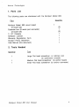
1. Parts List
The following parts are distributed with the Multipart Model 800.
Quantity
Multipart Model 800 circuit board
(2 board set)
Expander box (8 serial port connector)
(2 board set)
3 1/2" Diskette
Software License
Warranty Registration Form
Support Policy Statement
User Manual (this document)
2.
To~ols
1
(2)
1
(2)
1
1
1
1
1
Needed
Quantity
1
1
Large Flat head screwdriver, or ordinary coin
(to open/close chassis)
Medium Flat head screwdriver (to anchor board)
Small Flat head screwdriver (to anchor connector)
Multiport Model 800 User Manual
4
Aurora Technologi es
Installat ion
Please read these instructions thoroughly before attempting to install the
Multiport. Minor mistakes during installation could result in damage to
the product.
The Sun386i System Setup & Maintenance manual will be useful to have
handy. There are reference to this book throughout this manual.
Quicksta rt
- Power off Sun386i
Plug Multiport Board into AT Slot
-
Attach expander box
-
Hookup peripherals
-
Power on Sun386i
-
Login as root
cd /etc/modu les
tar xvf /dev/rfdiOc
-
enable modems
install
- enable peripherals
Multipart Model 800 User Manual
5
Aurora Technol ogies
Hardw are
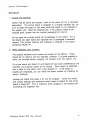
1. Unpack the contents:
Check that all items are present, refer to the parts list for a complete
description. The circuit board is wrapped in a charge resistant foil, be
sure to keep the board in this wrap while the board is not installed in
the system unit. Save the shipping box, if the product needs to be
shipped back, please use the original packaging for returns.
All the parts for a single board set is packaged in one carton. For a
two board set, each board and expander box is packaged in separate
cartons. The printed material and software is shipped in the carton
containing Board #1.
2. Verily Switches and Jumpers:
The board's switches and jumpers are preset at the factory. There
should be no need to set any switches, however, it is good practice to
verify the settings before plugging the board(s) into the system unit.
For a two board set, Board #1 and Board #2 have been predefined by the
switches and jumpers preset at the factory. Each board is identified
with a label on the carton that it was shipped in. If the boxes or
boards get misplaced, you can verify the board number by checking its
switch settings .
Unwrap the board and place it on the foil wrapper. Verify the switch
and jumper settings and remember which board is Board #1 and which
board is Board #2. This is important while plugging in the boards and
connecting the expander box.
Multipa rt Model 800 User Manual
6
Aurora Technologi es
Jumpers:
A jumper is a set of two parallel pins protruding from the board. They
can be left unconnected by leaving them exposed, or they can be
connected by placing a conductive jacket over both pins. A jumper is
CLOSED if this jacket is in place, making a connection. A jumper is
OPEN if the jacket is left off, leaving the pins unconnected. The
jumpers are labeled with a number printed on the circuit board next to
the set of pins for that jumper. The jumper settings are defined as
follows:
Board #1
Board #2
3 -OPEN
5 -OPEN
10- OPEN
11- OPEN
12- OPEN
15- CLOSED
E1/E2- CLOSED
3 -OPEN
5 -OPEN
10- OPEN
11 -OPEN
12- CLOSED
15- OPEN
E1 /E2- CLOSED
Switches:
There are eight switches contained in one switch package, each switch
is numbered. Looking at the switches, with the numbers facing up and
under the switches, the switch is OFF when the switch arm is pushed
up. The switch is ON when the switch arm is pushed down. The switch
settings are defined as follows:
Board #1
Board #2
1 -OFF
2- OFF
3- OFF
4- ON
5- ON
6- ON
7- OFF
8- OFF
1 -OFF
2- ON
3- ON
4- OFF
5- ON
6- ON
7- OFF
8- OFF
Multiport Model 800 User Manual
7
Aurora Techno logies
3. Turn off power of the Sun386i
Notify all users that you will be turning off the computer.
done by typing:
This can be
{system :1}wall
This compute r is being powered down, please logoff.
<AD>
{system :2}
<AD> represents pressing the control and D key at the same time.
Make sure all all applications have been stopped or terminated, this
will elimina te any possibil ity of losing data.
If you are running in the Sunview Windowing system you can shutdown
the system from the Desktop Menu. Select the Shutdo wn option from
the IExits submenu. Once you see the following message:
writing all filesystem information to disk (syncing) ... done
SunOS halted
it is safe to turn off the power. Be sure to turn off power to all
peripherals including the monitor and/or peripheral box after turning
off the system unit.
If you cannot access the Shutdown menu option, then you must
manually shutdown the system. Login as root (see your system
administrator if you do not have the root password). Then at the
prompt type
{system: 3} /etc/hal t
and the comput er will start its software halt sequence. It will take
several minutes for this procedure. Watch for the above message
indicating the SunOS has halted. Once you see this message it is safe
to turn off the power. Be sure to turn off power to all peripherals
including the monitor and/or peripheral box after turning off the
system unit.
Multipo rt Model 800 User Manual
8
Auror a Techn ologie s
Refer to the Sun386i Syste m Setup and Maintenance, Chapt er 2,
PowE3ring Down (pg. 37) for detailed instructions.
4. Open Sun386i chassis
WARNING: Make sure the system unit's power cord is unplugged.
shock.
Failur e to take this preca ution can result in electr ical
Orient the system unit so the floppy drive opening is facing you.
.
Remove the left side panel by unscrewing the large flat head screw
the
You can use a large flat head screwdriver or a large coin. Swing
its
top of the panel away from the chassis and lift the panel from
hinges.
(pg.
Refer to the Sun386i Syste m Setup and Maintenance, Appen dix B
102-1 03) for furthe r assist ance.
Multip ort Model 800 User Manu al
9
ill
I
Aurora Technologies
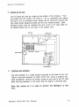
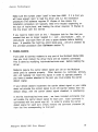
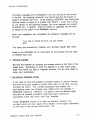
5. Choose an AT slot
The AT slots will now be visible at the bottom of the chassis. From
the bottom the the system unit there is 1 XT (1 connector) slot, above
that are 3 AT (2 connector) slots. Above the AT slots you will see the
Sun frame buffer (graphics board) and the Sun memory board. Each
Multipart board must be installed into one of the 3 AT slots (Slot 5-7
as labeled below and on the back of the system unit.)
Disk drive
Diskette drive
,--------.,
L-------...J
System speaker
6.
Remove slot protector
The slot protector is a metal bracket mounted to the back of the unit.
There is one slot protector for each AT/XT slot. Using a medium flat
head screwdriver, remove the anchor screw on any one of the AT slots.
Save this slot protector in the event that the board is removed later.
Save this screw as it is used to anchor the Multipart in this
slot.
Multipart Model 800 User Manual
10
Auror a Techn ologie s
AT
Refer to the Sun386i System Setup and Maintenance, Appen dix B,
and XT Boards (pg. 114) for further assistance.
BE CAREFUL NOT TO DROP ANY METAL PARTS INTO THE CHASSIS!!
7. Insert board into chassis
Each board can now be plugged into the chassis. Position the board
and
with the 62 pin female connector facing the back of the chassis
board
slide the board carefully into the guides for the correc t slot. The
against
should slip into· the connectors and the flange should rest flush
s.
the chassis. Firmly seat the board by pressing down with your thumb
Anchor the board with the screw from the slot protector.
With a two board set there is
however, it tends to be easier
Board #2 when connecting the
putting Board #1 above (with
#2 is desira ble.
no preference to board positioning,
to remember that Board #1 is above
expander boxes into the boards. Thus
the system standing straig ht up) Board
AT
Refer to the Sun386i Syste m Setup and Maintenance, Appen dix B,
ami XT Board s (pg. 115) for further assistance.
Multip ort Model 800 User Manu al
11
Auror a Techn ologie s
8. Close Sun386i chassis
the
Slip the side panel onto the hinges of the system unit and swing
in
top of the panel closed. Tighten the large flat head to hold the panel
place .
Multip ort Model 800 User Manu al
12
Aurora Technologi es
NOTE: Failure to close the chassis can cause damage to the Multipart
board and possible parts of the system because the cooling fans will
not properly cool the system. Be sure to replace the side panel before
turning on the power of the Sun386i.
9 . .Q.Q.n.nect serial expander box
If you are installing a two board set, it is important to know which is
Board #1 and which is Board #2. If you followed the recommendation
in Hardware section 6 then Board #1 should be above Board #2 (with
the system standing straight up).
Slip the male connector on the cable of the serial expander box onto
the female 62 pin connector of the board. Anchor the connector with
the screws included on the connector using a small flat head
screwdrive r.
10. Turn on power of the Sun386i
With all the connections restored, the computer can now be turned on.
Remember to turn on any other peripherals prior to turning on the
system unit.
11 . .Q.Q.cmect peripherals
You can now connect all peripherals to the serial expander box.
12. Rer)1oving Multipart Board
You might need to remove the board from your system to send it back
to Aurora Technologies for warranty service or to move it to another
system.
Follow Hardware sections 3,4 to power down the Sun386i and open
the chassis. Next, disconnect the serial expander box cable from the
connector(s) at the back of the system unit. Use a small flat head
screwdriver to unscrew the two mounting screws on the connector(s)
and carefully pull the cable connector from the Multipart board
connector( s).
Multiport Model 800 User Manual
13
Auror a Techn ologie s
Unscrew the anchor screw that holds the Multipart board(s) in place
using a medium flat head screwdriver.
Save this screw, as it is used to anchor the slot protector in place.
g
Remove the Multipart board gripping the board by the edges, tuggin
gently until you feel the board decouple from the connector. If the
board doesn't decouple easily, rock it gently back and forth. It should
slide easily along the plastic guides until it is free of the slot.
from
Place the board back into its charge resistant foil to protec t it
any stray static charges.
Replace the slot protector (saved from the steps taken in Hard ware
in
section 6) and use the use the anchor screw to hold the protector
be
place. This protector must be replaced, otherwise the cooling might
affected and system parts might overheat or be damaged.
Multip art Model 800 User Manu al
14
Auror a Techn ologie s
Next follow the steps in Hardware section 8,10 to return the
Sun386i to operation.
Multip ort Model 800 User Manu al
15
ill
Aurora Techno logies
Softw are
There is one 3 1/2" double sided double density diskette (720K, low
density) included in the package containing the Multipa rt Model 800 UNIX
device driver. This section describ es how to install this UNIX device
driver.
20.3r--t o.3&'
~,.,; •llloS"-
Each copy of the UNIX driver has a unique serial numb er./ This serial
number has been assigned to you. This is your only copy of the driver so
you must take every precaution to preserve the contents of the floppy:
store the diskett e in a clean, dust free environ ment.
keep the diskett e out of direct sun-lig ht or extreme sources
of heat or cold.
keep the diskett e away from strong magne tic fields.
make sure the diskett e is write protec ted.
1. Write protec t the diskett e
The diskett e should alread y be write protected, howev er you should
verify this. Turn the diskett e up-side down (label side down with the
metal hub showing). If you hold the diskette at the label end,_ the write
protec t notch is in the lower right corner.
Multip ort Model 800 User Manua l
16
I
il
Aurora Techno logies
If you can see through the notch, the disk is write protected. If the tab
is covering the notch, slide the tab all the way down until it clicks and
you can see through the notch. Now your diskette is write protected.
2. Insert disket te
Hold the diskett e with the label side up and insert the diskett e into the
drive.
Push the diskett e firmly until the release button in the front of the
drive pops out.
3. Load the diskett e
Login as root. If you do not know the root passw ord, see your system
admini strator . Once logged in, type the following comma nds:
{system :1} cd /etc/mo dules
{system :2} tar xvf /dev/rfd iOc
softwa re requires at least 43 Kbytes of free space to be able to
unload the softwa re from the diskett e (and run the installa tion
procedure). To check if there is enough space type:
ThE~
{system :3} df
Look for the line:
Filesyst em
/dev/ro ota
kbytes
5037
used
3443
Multip art Model 800 User Manua l
avail capacity
76%
1 090
Mounted on
I
17
Aurora Technol ogies
Make sure the number under "used" is less than 4980. If it is then you
will tlave enough room to load the driver and run the installation
procE~dure (The software requires 21 Kbytes of free space, the
installation procedure will typically need 8-10 Kbytes depending on
the size of /etc/rc.local, and loading the driver requires 13 Kbytes to
link the driver with the kernel)
If you need to make room on the I filesystem look for files that you
created that are no longer needed in I, !etc , /etc/mo dules , /dev , or
1/ost+found and save them off onto a spare diskette before deleting
them. A possible file might be letclrc.l ocal.sa ve , which is created by
the uninstall procedure (see Softwa re section 7).
4. Enable modems
If you plan to connect modems to any port of the Multipart Model 800,
now you must instruct the driver there will be modems connected.
This is done by modifying letclmo dules/m ms.exe c before loading the
driver.
Modems require the carrier detect signal (pin 20 on the Multipart
serial port) to operate properly. Other devices (i.e. terminals, printers,
etc.) will typically not need this signal in order to operate properly. If
you have a modem attached to the port, you must enable the carrier
detect signal.
If your device doesn't implement the carrier detect signal or your cable
does not provide the correct signal to pin 20 (carrier detect) then the
default setup, with the carrier detect signal disabled, is satisfactory.
In ttle file /etclmo du/es/m ms.exe c , we have included commands that
will enable the carrier detect signal for each port. Each command is
commented with the pound sign (#). In order to enable the carrier
er (#)
detr:~ct signal for each port, simply remove the comme nt charact
from the line corresponding to that port.
Multipo rt Model 800 User Manual
18
Ill
I
Aurora Technolo gies
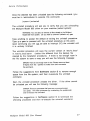
You must first decide which ports will connect to modems. Then you ·
must determine which special device file corresponds to each port
(/dev/ttybO correspo nds to port 0, /dev/ttyb1 to port 1 ,... /dev/ttyb7
to port 7). Find the entries in letclmod uleslmm s.exec and remove the
comment characters (#) from those lines.
For example, if there was a modem connected to ports 2, 4, 5 & 7 of
Board #1 then the resulting file would look like:
# Below are the commands that will activate the carrier detect signal
#for each individual port. All of theses commands are commented out
# and therefore no executed. If you need hardware carrier detect for
# a port, remove the comment character {#} from the line corresponding
# to the appropriate port.
#/usr/etc/t tysoftcar -n /dev/ttybO
#/usr/etc/t tysoftcar -n /dev/ttyb1
/usr/etc/tty softcar -n /dev/ttyb2
#/usr/etc/t tysoftcar -n /dev/ttyb3
/usr/etc/tty softcar -n /dev/ttyb4
/usr/etc/tty softcar -n /dev/ttybS
#/usr/etc/t tysoftcar -n /dev/ttyb6
/usr/etc/tty softcar -n /dev/ttyb7
The lines corresponding to ttyb2, ttyb4, ttyb5 & ttyb7 (ports 2, 4, 5 &
7) have the comment characters (#) removed in order to activate the
carrier detect signal.
5. Run install procedure
Once the diskette has been unloaded type the following command (you
must be in /etc/modules to execute this command):
{system:4 } install
Multiport Model 800 User Manual
19
I II
Aurora Techno logies
A copyrig ht message will be displayed:
Aurora Technologies, Inc.
Multiport Model 800
Copyright (c) 1988 Aurora Technologies, Inc.
Copyright (c) 1988 Harris Corp.
All Worldwide Right reserved
Licensed to Aurora Technologies by Harris Corp.
Then you will be asked to verify that you want to install this driver
onto your system (called system):
You are now going to install the Multiport Model 800 driver onto system.
Do you wish to continue? (default: yes): yes
Type1 anything to accept the defaul t of installing the driver onto
system. Type n or no to terminate the installation procedure. Upon
continuing you will ll..Q1 be able to interrupt ("C) the installation until it
is entirel y finishe d.
Before installing the driver, the installation proced ure will check to
see if a Multipart streams-based driver is already loaded and unload it.
(there cannot be more than one Multipart streams based driver loaded
at a time) If the driver cannot be unloaded you will see the following
message:
There is a Multiport streams driver already loaded in this system.
Install must unload this driver before it continues with the
installation. However, there are processes that have one or more
ports open (ex: getty). Kill these processes (by unattaching
the peripherals) and re-execute this command.
At this point the installation procedure will termin ate and you will
have to terminate the processes that are holding the serial ports open.
This will typically be done by unattaching the peripherals that were
previously attached to the Multipart serial ports. If you still get the
above message type:
{system :5} ps ax
Multip art Model 800 User Manua l
20
Aurora Techno logies
and look for processes that might have a Multipart serial port open (ex:
getty, tip, kermit. .. ). Kill these processes by typing:
{system: 6} kill
-9
12345
where 12345 is the process number of the offending process. If you
still get the message after trying to install the driver try loading the
original diskette and uninsta /1 that software and then Shutdo wn the
system. Once the system is powered back up, load this diskette and try
the installation again. (Softw are sections 2 - 6)
Continuing with the installation, after the checking for (and unloading)
an existing Multipa rt streams -based driver the installat ion procedure
will store the following command in the system boot file,
/etc/rc. local :
modload -conf mms.conf -exec mms.exec mms.o
This is the command used to load the driver into the system (See
moctload (8), modun load (8), modsta t (8). As a result of this, every
timet the comput er is powered up the Multipart driver will
automatically be loaded and operational. A backup copy of the original
system boot file is stored in /etclrc. local. orig . Remember this file,
it's a potential file you can rename and save to free disk space.
Tho installa tion procedu re will print:
modifying /etc/rc.local to include modload command
If there is not enough room in the file system to make the backup copy
(/etc/rc /local/o rig) you will see the following messag e:
ERROR: There is not enough room in /etc. Please remove at least
8 Kbytes from the I partition to make room and re-execute
this command.
8 Kbytes is the standard size of /etc/rc.local howeve r your version
might be differen t if it has been modified. Follow the suggestions
from Softwa re section 3 ... to remove enough space from the file
system, and then re-execute the install command.
Multipo rt Model 800 User Manual
21
Aurora Techno logies
Once /etc/rc.l ocal is modifie d the installat ion procedu re will print:
original /etc/rc.local is saved in /etc/rc.local.orig
If /etc/rc.l ocal had already been modified to include the modload
command you would have seen the message below instead of the above
messages:
/etc/rc.local already modified to include Multiport Model 800
Next the installation procedu re will load the driver so that you can
immedi ately use the Multipa rt Model 800.
If the board is not plugged in or isn't properly seated you will see the
followin g messag e:
ERROR: The Multiport BOARD could not be found. Try plugging
in the board or reasting it, and then re-execute this command.
Follow the procedu res in the Hardwa re section s 3-8 to plug or reseat
the board. If the board is already plugged in, check to make sure it is
in the correct AT slot by refering to the diagram in the Hardw are
section 5.
While loading the driver, the linker will need approxi mately 13K bytes.
If there is not enough room on the filesystem you will see the
followin g messag e:
ERROR: The linker failed. If you ran out of disk space please
remove at least 15 Kbytes from the I partition. If there
was an "Undefined" then please insure that you are running
SunOS 4.0.1 or later version.
Follow the sugges tions from the above section, Softwa re section 3...
to remove enough space from the file system, and then re-execute the
install comma nd.
Multipa rt Model 800 User Manual
22
Aurora Techno logies
The same message will be displayed if you are running an old version
of SunOS. By checking /etclmo td you should see that the version is
equal to or greater than 4.0.1. Or by checking /VERSI ON you should see
that the version is equal to or greater than BL9F.3 . If you are running
an old version of the operating system, you must upgrade your system
to SunOS 4.0.1 or greater. Once the system is upgraded you will have
to repeat all the steps in the Softwa re section .
When the installation has completed the following message will be
printed :
If you wish to uninstall this driver, just type uninstall
done.
You have just successfully installed your Multipart Model 800 driver.
Refer to the README file for information on the devices that are used
to address each port.
6. Remove diskette
Remove the diskette by pressing the release button at the front of the
floppy drive. Remember to store the diskette in a safe, clean place
away from direct sun light or magnetic sources. You are now ready to
setup your peripherals.
7. Uninsta lling Multipa rt Driver
If you need to move the board(s) to another system or need to remove
the driver from your system to create more room on the disk, you can
uninstall the driver. The uninstall procedure was loaded into
/etc/mo dules when the software was loaded from the diskette in
Softwa re section 3. However, it is best to load the diskette again
because the uninstall procedure might have been removed or
overwri tten since the driver was first installed.
Follow Softwa re section 3 to load the diskette, however, the
uninstall script will only require 8-10 Kbytes of free space depending
on the size of the current /etclrc.l ocal file.
Multipa rt Model 800 User Manual
23
ill
I
Aurora Technolo gies
Once the diskette has been unloaded type the following command. (you
must be in /etc/modules to execute this command)
{system:1 } uninstall
The uninstall procedure will ask you to verify that you are uninstalling
the Multipart Model 800 driver on your machine (called system):
WARNING: You are about to remove all files related to the Multiport
Model 800 from system. Do you wish to continue? (default: no): yes
Type
Type
Upon
it is
anything to accept the default of exiting the uninstall procedure.
y or yes to proceed with the uninstall procedure at this point.
continuing you will D..Q.1 be able to interrupt (I'C) the uninstall until
entirely finished.
The uninstall procedure will save the current version of /etc/rc.lo cal
(notice this different from the backup file
in letclrc.lo cal.save
created by the installation procedure). If there is not enough room in
the file system to save a copy you will see the following message:
ERROR: There is not enough room in /etc. Please remove at least
8 Kbytes from the I partition to make room and re-execute
this command.
Follow the suggestions from Softwar e section 3 to remove enough
space from the file system, and then re-execute the uninstall
command.
Next, the uninstall procedure unloads the driver.
be unloaded you will see the following message:
If the driver cannot
ERROR: There are processes that have one or more ports open
(ex: getty). Kill these processes (by unattaching the peripherals)
and re-execute this command.
Follow the suggestions in Softwar e section 5 to terminate the
offending processes and then re-execute the uninstall command.
Multiport Model 800 User Manual
24
Aurora Techno logies
Once the driver is unloaded the uninstall procedure will remove all of
the files associated with the Multipart Model 800 files and you will
see:
removing Multiport Model 800 files
The files removed all exist is /etc/modules and are: mms.o, mms.conf,
mms.exec, mms_copyright, install, uninstall, and README.
Once the files are removed the system will respond with:
done.
You have now uninstalled the Multipart Model 800 from your system.
Follow the directions in the Hardw are section 12 to remove the
Multipa rt board(s) from your system.
Multip ort Model 800 User Manua l
25
Aurora Techno logies
Techn ical
Aside
1. Changin g interrup t reguest line
If you have several boards installed in the system, you might have a
conflict with interrup t requests. The interrup t request pre-set at the
factory is 15 for Board #1 and 12 for Board 32. If this has to be
changed you have a choice of 3,5, 10,11,12 & 15. To change an interrupt
request you must first modify letclmo dules/m ms.con f and then
change a jumper on the board.
Login as root (see your system administrator if you do not know the
root password). Edit letclmo dules/m ms.con f . If you have a one board
set, there will be one line in the file to modify. The line will look like
device
mmsO at atmem ? csr OxECCOOO irq 15 priority 4 dmachan Oxff
The interrup t level is defined by the parameters irq 15 . Change the 15
to the interrup t request you choose (3,5, 10,11,1 2 or 15).
If y()u have a two board set there will be 2 lines in the file, one per
board. The line beginning with device mmsO represents Board #1, the
line beginning with device mms1 represents Board #2. Change the
interrup t request as descibed above for the appropr iate board.
Next you must change a jumper on the board to switch the interrupt
levol used by the Multipart board. Power off the system and remove
the board (Hardw are section 12). The jumpers numbered 3,5, 10,11,1 2
& 15 are jumpers corresponding to the interrup t level used by that
board. Remove the jumper jacket from the existing jumper and place it
onto the jumper corresponding to the interrupt level you choose.
NOTE: There can only be 1 (one) jumper closed among the jumpers
labeled 3,5, 10,11,1 2 & 15. These jumpers corresp ond directly to the
interrupt level used by the board, closing more than one of these
jumpers will cause serious degrada tion of system perform ance.
Once the jumper has been changed, replace the board back into the
system. Follow the directio ns in Hardw are sections 7-10.
Multipo rt Model 800 User Manual
26
,Ill I
Aurora Technolo gies
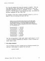
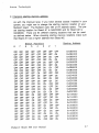
2. Changing starting memory address
As with the interrupt level, if you have several boards installed in your
system, you might nee to change the starting memory location of your
Multipart board. The Multipart uses 16K of AT address space. The preset starting location for Board #1 is OxECCOOO and for Board #2 is
OxEA8000. There are 64 different starting locations that can be used
as defined below. When choosing starting memory locations make sure
that Board #1 has a higher address than Board #2.
8
7
a=F a=F
a=F a=F
a=F a=F
a=F a=F
a=F a=F
CFF a=F
a=F a=F
a=F a=F
a=F a=F
a=F a=F
a=F a=F
a=F a=F
a=F a=F
a=F a=F
a=F a=F
a=F a=F
a=F a=F
a=F a=F
a=F a=F
a=F a=F
a=F a=F
a=F a=F
a=F OFF
OFF a=F
a=F a=F
a=F a=F
Starting Address
PQ~liliQns
Swit~h
6
5
4
3
2
1
a=F
a=F
a=F
a=F
a=F
a=F
a=F
a=F
a=F
a=F
a=F
a=F
a=F
a=F
a=F
a=F
a=F
a=F
a=F
a=F
a=F
a=F
a=F
a=F
a=F
a=F
a=F
a=F
a=F
a=F
a=F
a=F
a=F
a=F
a=F
a=F
a=F
a=F
a=F
a=F
a=F
a=F
a=F
a=F
a=F
a=F
a=F
a=F
a=F
a=F
(]\J
a=F
(]\J
(]\J
(]\J
a=F
(]\J
a=F
a=F
(]\J
(]\J
a=F
(]\J
(]\J
(]\J
(]\J
a=F
a=F
a=F
(]\J
a=F
(]\J
a=F
a=F
a=F
a=F
(]\J
(]\J
(]\J
(]\J
(]\J
a=F
a=F
a=F
(]\J
(]\J
(]\J
(]\J
a=F
(]\J
(]\J
(]\J
(]\J
(]\J
a=F
a=F
a=F
a=F
a=F
a=F
a=F
a=F
a=F
a=F
a=F
a=F
(]\J
a=F
(]\J
(]\J
(]\J
a=F
a=F
OFF
(]\J
OFF
a=F
GJ
GJ
OFF
(]\J
(]\J
(]\J
(]\J
d=F
(]\J
a=F
a=F
(]\J
OFF
(]\J
(]\J
(]\J
(N
(]\J
(]\J
(]\J
(]\J
(]\J
(]\J
a=F
a=F
(]\J
a=F
(]\J
(]\J
(]\J
a=F
a=F
OFF
OFF
(]\J
OFF
a=F
(]\J
GJ
Multipart Model 800 User Manual
Ox08000 0
Ox08400 0
Ox08800 0
Ox08COOO
OxOA800 0
OxOACOOO
OxOB800 0
OxOBCOOO
OxOCOOOO
OxOC4000
OxOC8000
OxOCCOOO
OxODOOOO
OxOD4000
OxOD8000
OxODCOOO
Ox10800 0
Ox12400 0
Ox20800 0
Ox22400 0
Ox30800 0
Ox32400 0
Ox40800 0
Ox42400 0
Ox50800 0
Ox52400 0
27
Aurora Technologi es
a=F
a=F
a=F
a=F
a=F
a=F
a=F
a=F
a=F
a=F
a=F
a=F
a=F
a=F
a=F a=F
a=F. a=F
a=F a=F
a=F' a=F
a=F' a=F
CFF a=F
O:F a=F
O:F a=F
a=F a=F
a=F a=F
a=F a=F
a=F a=F
a=F
CFF a=F
a=F
CFF a=F
a=F
a=F
a=F"
a=F
CFF
a=F
a=r•. a=F
a=F a=F
a=r.. a=F
a=F a=F
OFF a=F
OFF a=F
OFF a=F
OFF OFF
a=r.. OFF
OFF OFF
a=r..
OFF
OFF OFF
a=F
a=F
a=F
a=F
a=F
a=F
OJ
OJ
OJ
OJ
OJ
OJ
OJ
OJ
OJ
OJ
OJ
OJ
OJ
OJ
OJ
OJ
OJ
OJ
OJ
OJ
OJ
OJ
OJ
OJ
OJ
OJ
OJ
OJ
OJ
Q\1
Q\1
OJ
OJ
OJ
OJ
OJ
OJ
a=F
a=F
a=F
a=F
a=F
a=F
a=F
a=F
a=F
a=F
a=F
a=F
a=F
a=F
a=F
OJ
OJ
OJ
OJ
OJ
OJ
OJ
OJ
OJ
OJ
OJ
OJ
OJ
OJ
Q\1
Q\1
OJ
OJ
OJ
OJ
OJ
OJ
a=F
a=F
a=F
a=F
a=F
a=F
a=F
OJ
OJ
OJ
OJ
OJ
OJ
OJ
OJ
a=F
a=F
a=F
a=F
a=F
OJ
OJ
OJ
OJ
OJ
OJ
a=F
a=F
a=F
OJ
OJ
OJ
OJ
a=F
a=F
a=F
a=F
OJ
OJ
OJ
OJ
a=F
a=F
a=F
a=F
a=F
a=F
a=F OJ
a=F OJ
a=F OJ
a=F OJ
a=F
OJ
a=F
OJ
OFF
OJ
OFF
OJ
OJ
OJ
OJ
OJ
a=F
OJ
OJ
a=F
a=F
OJ
a=F
a=F
OJ
OJ
a=F
a=F
OJ
OJ
a=F
a=F
OJ
OJ
a=F
a=F
OJ
OJ
a=F
a=F
OJ
OJ
a=F
OFF
OJ
OJ
OFF
OFF
a=F
OJ
a=F
OJ
a=F
OJ
a=F
OJ
a=F
a=F
OJ
a=F
OJ
a=F
OJ
a=F
OJ
a=F
OJ
a=F
OJ
a=F
OJ
a=F
OJ
a=F
OJ
a=F
OJ
a=F
OJ
a=F
OJ
OFF
Q\1
Q\J
Q\1
Q\J
OFF
Q\1
Q\1
Q\1
Q\1
Multiport Model 800 User Manual
Ox608000
Ox624000
Ox708000
Ox724000
Ox808000
Ox824000
Ox850000
Ox908000
Ox924000
OxA08000
OxA24000
OxASOOOO
Ox808000
Ox824000
OxBSOOOO
OxC08000
OxC24000
OxCSOOOO
OxC8COOO
OxD08000
OxD24000
OxDSOOOO
OxD8COOO
OxE08000
OxE24000
OxESOOOO
OxE8COOO
OxEA8000
OxE54000
OxECCOOO
OxF08000
OxF24000
OxFSOOOO
OxF8COOO
OxFA8000
OxF54000
OxFCCOOO
28
I il
Aurora Techno logies
The switch is OFF when the switch arm is pushed up.
when the switch arm is pushed down.
The switch is ON
First, modify letclm odules /mms. conf . Follow the instructions in the
previous section on Changing Interrupt Request Level. The only
difference is that you modify the paramters that define the starting
memo ry locatio n
mem OxECCOOO
Change OxECCOOO to the starting memory location you choose from the
above table.
Next open the system unit by following Hardw are sections 3 & 4 (you
do not need to remove the board in order to change the switch
settings). The switches are visible and accessible from the side. They
are closer to the front of the system unit, next to the LED pack. The
switches are numbered where switch #8 is the closest to the back of
the system unit and switch #1 is closest to the front of the system
unit. Set the switches according to the address picked from the table.
Once the switches are set, follow Hardw are sections 8 & 1 0 to
restc>re the system to operation.
3. Reconnecting a modem to a different port
If you have already installed the Multipart driver and need to switch
the modem to a different port, you will have to indicate the change to
the Multipart driver. This is done by unloading the driver (all
periph erals must be unconfigured first), modifying
letclm odules lmms. exec and loading the driver again.
Don't get unloading confused with uninstalling the driver. Unloading
the driver is essent ially de-act ivating it (the instruc tions are below),
you do not need to remove the driver with an uninstall.
You must first login as root before you attempt to unload the driver.
If you do not know the root password see your system administrator.
Multip ort Model 800 User Manua l
29
Aurora Technologi es
Find out the id of the Multipart driver:
{system:1} /usr/etc/mo dstat
B-major
Size
ld Type Loadaddr
Drv fdOOOOOO 7000
0
C-major
58.
Sysnum
Mod Name
mmsdrv
In this case look for the row with "Mod name" equal to mmsdrv . The
first parameter of that row is the module id (in this case, 0).
Unload the driver using modunload and specifying the id of the driver:
{system:2}
/usr/etc/mod unload -id 0
If you see the message:
can't unload the module: Device busy
then there are peripherals that are still configured. These must be
unconfigured (using SNAP, or disabling getty, etc.) before trying the
modunload command again.
Next, modify letclmodul es/mms.ex ec
section 4.
as explained in Software
Once the file has been modified, you can. now reload the driver and
restore operation of your Multipart board. Type:
{system:S}
{system:6}
cd /etc/module s
modload mms.o -conf mms.conf -exec mms.exec
Now you should reconfigure you peripherals using SNAP to return your
Multipart Model 800 to full operation.
Multiport Model 800 User Manual
30
ill
I
Aurora Technolo gies
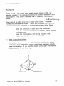
4. Cable design
Designing the proper cables is very important for the proper operation
of your Multipart product. Below is a description explaining the
signals on the Multipart ports to allow you to create the specific cable
for your application .
Signal Name
Receive Data
Transmit Data
Clear to Send
Request to Send
Ground
Data Terminal Ready
Carrier Detect
.5n
2
3
4
5
7
8
20
lnQutLO!.!tl2!.!t
Input
Output
Input
Output
Output
Input
Below are sample cable designs for typical connections:
Local Terminal
2
3
-------------------
2
3
7
----------
7
20
--------
20
Multiport Model 800 User Manual
IBM PC/XT/AT
2
3
4
5
7
8
20
--------- 2
------""'·--
---------------------------------
-------
3
4
5
7
8
20
TyQical Modem
2
---------
----------------------------------20 -·-----
3
4
5
7
8
3
2
5
4
7
20
8
31