1
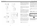
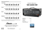
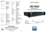
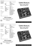
USERS MANUAL
CONTENTS:
INTRODUCTION
FRONT AND REAR PANEL
FILTERS
MAINTENANCE
BLOCK DIAGRAM
TECHNICAL SPECIFICATIONS
DESIGNED AND DEVELOPED BY EBS SWEDEN AB
GRINDSTUVÄGEN 44-46, SE-167 33 BROMMA, SWEDEN
+46-8-735 00 10, FAX : +46-8-735 00 05
E-MAIL: [email protected]
WEB: www.ebssweden.com
June 2009
PAGE:
2
3
4
5
6
7
INTRODUCTION • GETTING STARTED
TECHNICAL SPECIFICATIONS
The EBS ClassicT90 is an all tube
amplifier head, extremely easy to dial-in. It
is designed to match the EBS ClassicLine
cabinets in all styles and situations. The
sound of the ClassicT90amp is pure vintage,
yet with a recognizable transparent ’EBS’
sound that let your playing style and the
character of your instrument speak.
Versatility is provided by a carefully
designed EQ section. These brief tutorials
will help you to become acquainted with
some of the features of the EBS
ClassicT90.
BUILDING THE SOUND...
GETTING STARTED...
10. Proceed to the prescence knob. This
control adjusts the high frequency
response of the power amp and lets
you define the "crunch" when
distorting the amp.
INPUT:
Your EBS ClassicT90 features a
tone shaping circuit that will enable you
to create a variety of vintage bass sounds.
9.
1. Carefully unpack the bass head.
2. Connect a speaker to the head. Make
sure that the impedance of the cabinet
match exactly with the output of the
T90.
3. Turn down the Volume and set all other
controls to mid position.
The bass and treble filters are
basically of the boost/cut design.
This means that the controls
practically boost or cut the selected
frequency band.
Gradually increase or decrease the
level and tone controls. Notice how
the sound is affected.
This was a brief tutorial of EBS
ClassicT90. As you go on further in this
manual, you will learn how to use and
utilize all of the useful features that the
EBS ClassicT90 offers you.
4. Power up the head and wait five(5)
minutes for the head to warm up. The
tubes should now glow.
5. Connect your instrument to one of the
inputs. If your bass is active or has high
output it is recommended to use the
active input, otherwise use the passive
one.
1 Mohms (passive)
100 kohms (active)
-20dBv (passive)
-8dBv (active)
Nominal Input Level
TONE CONTROLS:
8.
Input Impedance
Bass Filter:
Type
Treble Filter:
Type
0 - +12 dB @ 5 kHz
(Pwr amp feedback)
PRESCENCE:
BALANCED OUTPUT: Output Level
XLR Connections
Options
nominal
- 10 dBv
1-GND, 2-Hot, 3-Cold
GND Lift
POWER AMP:
Continuous Output Power
Load Impedance
90 W RMS
4 or 8 ohms
TUBE SELECTION:
Input / Filter
Balanced Output / Buffer
Power Amp Driver
Power Amp
1x 7025 low noise
2x 12AU7
1x 12AT7
2x 6550
AUXILIARY INFO:
Power Requirements
Mains Protection:
max
Fuse
Dimensions (WxHxD):
Weight:
Specifications are subject to change without notice!
GOOD LUCK!
6. Toggle the standby switch so that the
associated lamp light up.
7. Move over to the VOLUME knob and
adjust for the desired output volume.
2
Shelving
+/- 12 dB @ 80 Hz
Shelving
+/- 12 dB @ 8 kHz
7
200 W
T1.5A (230/240V)
T3.15A (100/120V)
537 x 267 x 243 mm
21.1 x 10.5 x 9.57”
17.1 kg ( 38 lbs.)
BLOCK DIAGRAM
FRONT AND REAR PANEL
INPUTS - Connect your instrument to one
of these inputs, active or passive. Use the
active input for instruments with high output and the passive one for instruments with
low output. If both inputs are connected
only the passive input will work.
___________________________________
BALANCED OUTPUT - Is a high quality balanced output that functions as a line
box for connecting to PA mixing consoles
or to studio or broadcast recording units.
Lifting ground is a great aid in many
occasions. When required, set the GND
switch to OFF position to disconnect the
ground from the output.
This balanced output is a direct driven
tube output for best possible performance.
__________________________________
VOLUME - This knob controls the volume
of unit, for the exception of the balanced
output (XLR) which is not effected by the
this setting.
___________________________________
AC INLET - Connects the amp to the
mains. This inlet also houses the mains
fuse.
__________________________________
BASS and TREBLE - These two controls
the tone stack of the ClassicT90. The design
is purely passive, yet it is designed as a
boost/cut filter for best performance. No
feedback is present here, and this filter is
driven by a class A driving stage. See next
page for filter characteristics graph.
___________________________________
SPEAKER OUTPUTS – The two
Speakon® connectors allow you to
connect the amp to your favorite cabinets.
IMPORTANT: Use only ONE
speaker output and the one that is
matching the TOTAL speaker
impedance.
PRESENCE - Controls the high frequency
response over the poweramp feedback circuitry. Very useful for defining the "edge"
or "attack" of a sound. Note that this control
does not effect the balanced output..
___________________________________
,
STANDBY – This switch mutes the amp by
disconnecting the high voltage from the
tubes. The associated lamp indicated when
the amp is operable. When powering up,
allow the to amp warm up for a period of 5
minutes prior of activating with standby.
___________________________________
EBS will not take responsibility for
eventual hearing damages caused by
the powerful ClassicT90.
__________________________________
POWER – Powers the amp on or off.
___________________________________
6
3
FILTERS
MAINTENANCE
Typical filter characteristics for Bass and Treble filters:
CHANGING THE TUBES - Although it
may not be necessary due to tube
malfunction, changing the tubes once in a
while will regain the tone and bring back
high performance. There are however
some points that are important:
SETTING THE BIAS - Whenever the
power tubes have been changed it is
necessary to set the correct bias to ensure
long life operation. This is the procedure:
1.
2.
2.
3.
4.
1.
When changing the power amp tubes,
both tubes must be changed, and the
tubes need to be a matched pair.
Recalibration of the bias is always
necessary after installing new
power tubes.
3.
4.
The power tube driver, 12AT7 should
be changed every second time the
power tubes are changed.
5.
6.
The input tube, 7025, must be selected
for low microphony, low noise and
high gain. Alternately, you may use
an 12AX7 or ECC83 here.
IMPORTANT: Incorrectly set
bias may cause permanent damage
to the amplifier. If you are not
100% sure on how to do this,
please get in touch with a service
center.
The buffer and balanced out tube must
be same type as original, 12AU7.
TUBES PLACEMENT:
4
Power the amp at let it warm up for 5
minutes.
Connect a voltmeter to the bias
measurement point VA at the rear
panel.
Switch on the amp by toggling the
standby switch.
Adjust with the associated bias
trimmer so that the readout on the
meter is 35mV +/-2mV.
Repeat for other tube using point VB.
After first calibration repeat once for
verification of bias setting.
5