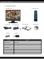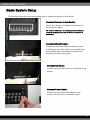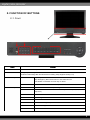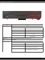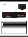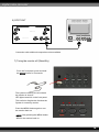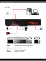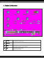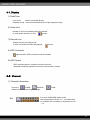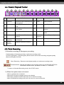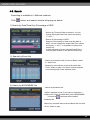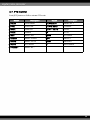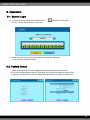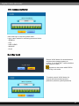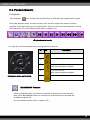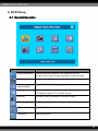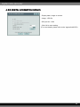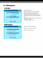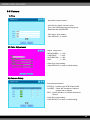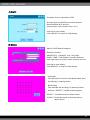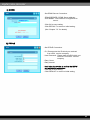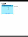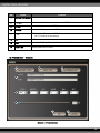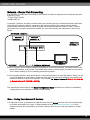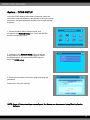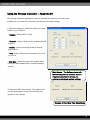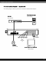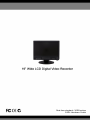
1
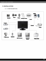
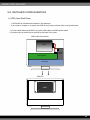
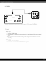
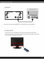
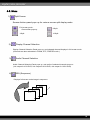
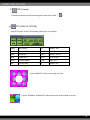
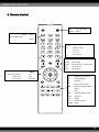
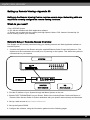
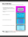
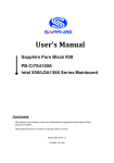
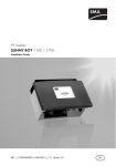
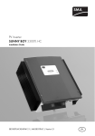
VER 1.0
CONTENT
S CHAP. 1 General Information
----------------------------------------------------------------
4
1-1.Installation & Safeguards
----------------------------------------------------------------
4
1-2Package Contents
----------------------------------------------------------------
5
1-3.Basic system setup
----------------------------------------------------------------
6
----------------------------------------------------------------
7
2-1.Front panel
----------------------------------------------------------------
7
2-2.Rear panel
----------------------------------------------------------------
9
----------------------------------------------------------------
10
3-1.Configuration
----------------------------------------------------------------
10
3-2.Detailed configuration
----------------------------------------------------------------
11
1)HDD (Hard Disk Drive)
----------------------------------------------------------------
11
2)Camera
----------------------------------------------------------------
12
3)Audio
----------------------------------------------------------------
12
4)Monitor
----------------------------------------------------------------
13
5)Power cable
----------------------------------------------------------------
13
6)SPOT OUT
----------------------------------------------------------------
14
7)Turning the monitor off
----------------------------------------------------------------
14
8)Others
----------------------------------------------------------------
15
----------------------------------------------------------------
16
4-1.Display
----------------------------------------------------------------
17
4-2.Channel Information
----------------------------------------------------------------
17
4-3.Menu
----------------------------------------------------------------
18
4-4.Record, Playback Panel
----------------------------------------------------------------
22
4-5.Panic Recording
----------------------------------------------------------------
22
4-6.Search
----------------------------------------------------------------
23
4-7.PTZ Control
----------------------------------------------------------------
24
4-8.USB Backup
----------------------------------------------------------------
25
----------------------------------------------------------------
26
5-1.System Login
----------------------------------------------------------------
26
5-2.Factory Default
----------------------------------------------------------------
26
5-3.Access Restriction
----------------------------------------------------------------
27
5-4.Key Lock
----------------------------------------------------------------
27
5-5.Playback(Search)
----------------------------------------------------------------
28
CHAP. 2Function of Buttons
CHAP. 3Installation
CHAP. 4Display Configuration
CHAP. 5Operation
2
CHAP. 6DVR Setup
----------------------------------------------------------------
29
6-1.General Operation
----------------------------------------------------------------
29
6-2.Configuration
----------------------------------------------------------------
30
6-3.Display
----------------------------------------------------------------
33
6-4.HDD Management
----------------------------------------------------------------
35
6-5.Camera
----------------------------------------------------------------
36
6-6.Record
----------------------------------------------------------------
39
6-7.Backup / Update
----------------------------------------------------------------
40
6-8.Network
----------------------------------------------------------------
41
6-9.Language
----------------------------------------------------------------
43
CHAP . 7 Network Setup
----------------------------------------------------------------
44
7-1.DVR Network Setup
----------------------------------------------------------------
44
7-2.DDNS
----------------------------------------------------------------
46
7-3Web Application
----------------------------------------------------------------
47
CHAP. 8Remote Viewer Program
----------------------------------------------------------------
48
8-1.IRS, Setup Operation
----------------------------------------------------------------
48
8-2.Backup Operation
----------------------------------------------------------------
51
8-3.Transmitter Operation
----------------------------------------------------------------
53
8-4.Player Operation
----------------------------------------------------------------
59
CHAP. 9Remote Control
----------------------------------------------------------------
62
Appendix
#1System Specification
----------------------------------------------------------------
63
#2Web Application Requirements
----------------------------------------------------------------
65
#3Setting up Remote Viewing
----------------------------------------------------------------
66
#4Using the Storage Calculator
----------------------------------------------------------------
72
#5Full Connectivity Diagram
----------------------------------------------------------------
73
#6DID
----------------------------------------------------------------
74
3
1. INSTALLATION
1-1. INSTALLATION & SAFEGUARDS
All safety and operating instructions should be read before operation.
Environment Condition for Installation
1. To prevent electric shock or other hazard, do not expose this unit to rain, moisture, or dust.
2. Place this unit in a well ventilated area and do not place heat generating objects on this unit.
3. This unit should not be located in an area where it is likely to be subjected to mechanical shock.
Before You Start
1. Ensure the power switch is in the OFF position prior to installation.
2. Opening or removing the cover may expose you to dangerous voltage or other hazards.
3. Operate this unit within the range of room temperature and humidity.
4. Supply power through the type of power source indicated on the manufacturer’s label and with the
power supply included in this unit.
5. Keep this unit out of direct sunlight and heat .
6. Make sure conductive material does not go into the ventilation hole.
.
Notice
1. Before initial configuration or operation, first set the TIME/DATE, then set this unit to the FACTORY
DEFAULT setting, lastly clear the HDD. Follow these steps in order, otherwise it may not record on
the HDD or not save the setting value. It may record, but you will not be able to search recorded
data.
2. This unit is compatible with high density HDD’s.
3. When setting RECORDING SETUP after installation, do not only set the RECORD
CONFIGURATION, but also SCHEDULE SETUP. Setting Schedule setup is necessary as this unit
records according to the Record type & Schedule setup. The default setting value for Schedule setup
is Continuous mode.
4. Stop recording before powering off this unit by entering the setup menu. Powering off while
recording may cause critical malfunctions such as Recording Error, Playback Error, or System Error.
4
1-2. Package Contents
1. DVR Main Unit
3. Power Cable
7. Batteries
2. Remote Control
4. Power Adapter
5. User’s Manual
6. Software CD
8. Mouse
Contents
Description
1. DVR Main Unit
DIGITAL VIDEO RECORDER
2. Remote Control
Remote Control
3. Power Cable
AC power supply to adapter
4. Power Adapter
DC power supply
5. User’s Manual
User’s Manual
6. Software CD
Remote Viewer SOFTWARE
7. Batteries
Batteries for Remote Control
8. Mouse
DVR function control
5
Basic System Setup
The following connections are recommended prior to loading the System for the first time.
Connect Cameras to the Monitor.
Please see ‘Chapter 3-2 Detailed configuration’ of
this manual for details.
TIP : Test the cameras prior to selecting a permanent mounting
location by temporarily connecting the Cameras and Cables to
your System.
Connect Ethernet Cable :
Connect one end of the Ethernet cable (for remote
monitoring) to one of the router’s (not included) LAN
ports and the other end to Monitor’s Network Port
located at the back of the system.
Connect the Mouse
Connect a PS/2 mouse to the port on the back of the
system.
Connect Power Cable:
Connect one end of the Power adaptor to the
monitor, the other end to an electrical outlet.
6
2. FUNCTION OF BUTTONS
2-1. Front
Name
Function
1. LED Indicator
Indicates the status of operation
2. PANIC
Emergency Recording
Continuous Recording With The Best Picture Quality (30fps,Highest Quality,1/1x)
3. Function Key1
EXIT
Stop Playback.
Stop Emergency Record and return to Schedule Record.
Cancellation of selection for main key or others
4. Function Key2
AUDIO
Select audio channel. Turn volume up/down
MENU
Enter SYSTEM MENU or for powering off the unit
MODE
Switch screen division from full screen to 16 split screen (in 1, 4, 9, 16
sequence )
SEARCH
Search recorded data on HDD
ZOOM
Zoom image
PTZ
Shift LIVE mode to PTZ control mode
SEQ
Auto camera image sequence in full screen mode
FRZ
Freeze live image
PIP
Picture In Picture mode
7
Name
5. Arrow key
Function
Navigate In The Menu And Selection Of Menu ( OK Button )
Enter
ON PLAYBACK : PAUSE FUNCTION
LEFT
ON PLAYBACK : BACKWARD PLAYBACK
RIGHT
ON PLAYBACK : PLAYBACK
UP
ON PLAYBACK : INCREASING SPEED
OF PLAYBACK
DOWN
ON PLAYBACK : DECREASING SPEED
OF PLAYBACK
6. USB Device
For Firmware Upgrade And USB Back up for DATA Saving
7. IR
IR Receiver
8. Selection of Camera
1~16 Button : Select camera channel in full screen mode
and Control of PTZ
1. +
ON ZOOM FUNCTION : ZOOM IN
2. -
ON ZOOM FUNCTION : ZOOM OUT
3. +
VOLUME UP,CONVERSION OF CHANNEL
PAGE,INCREASING OF PRESET NO.
4. -
VOLUME DOWN,CONVERSION OF CHANNEL
PAGE, DECREASING OF PRESET NO.
8
2-2. Rear
Name
1
RS 485
RS-232C
Function
Connection with PTZ Camera or other external devices using RS 485
Connection to external devices such as PC using RS-232C to control DVR
RELAY Output
Relay Output terminal
SENSOR Input
Sensor Input terminal
2
Ethernet
Connection to Ethernet devices
3
Camera Input
Connection with NTSC/PAL Cameras
4
Monitor Output
Connection with NTSC/PAL Composite Monitor
5
SPOT Output
6
DC Power
DC 12V 6.67A Adaptor
7
PS2 Mouse
Connection to PS2 Mouse
8
Audio
Audio input and output
9
Power DC12V
Power input and output
Connection from Analog backup output to external devices
9
3. INSTALLATION
3-1. CONFIGURATION
TCP/IP
Speaker
Alarm
Sensor
Remote Control
TCP/IP
Camera
RS-232C
Printer
PTZ Camera
RX BOX
SPOT Monitor
Composite
Monitor
Video Printer
10
3-2. DETAILED CONFIGURATION
1) HDD (Hard Disk Drive)
- 1 SATA HDD is included and installed in this package.
- If you need to change or re-install the HDD for any reason, please refer to the guide below.
1. Connect Main Board and HDD1 using the SATA cable and HDD power cable.
2. Screws must be inserted from outside at the back of the case.
HDD Cable Connection
HDD
POWER
BOARD
MAIN BOARD
I/O BOARD
HDD Fix
HDD
11
2) CAMERA
DC
LEVEL
V.P
VIDEO
CAMERA IN
DC
……
CH 1
CH 9
VIDEO
CH 8
CH16
LENS
AC24V/DC12
Rear view of CAMERA
……
AU 1
CH 1 - 4
AU OUT
MONITOR
SPOT
Connect cameras to the camera input on the rear panel of DVR marked CAMERA IN.
3) Audio
- Audio Input
1. There are 2 Audio Inputs.
2. Audio channel 1 is assigned for camera channel 1~4, audio channel 2 for camera channel
5~8.
* Audio inputs should be connected according to the assigned camera channels for audio
recording.
- Audio Output
1. 1ch Audio Output is available.
2. The selected audio channel at the DVR will be outputted.
12
4) MONITOR
CAMERA IN
……
CH 1
CH 9
CH 8
CH16
……
AU 1
CH 1 - 4
V ID E O A
IN
AU OUT
MONITOR
OUT
V IDE O B
IN
OUT
V IDE O C
IN
OUT
SPOT
Connect the video output marked MONITOR to the VIDEO-IN port of the Main Monitor.
5) POWER CABLE
Connect the DC 12V, 6.67A Adaptor to the power jack on the back side of the system.
Before turning on the unit, be sure all necessary devices such as power adaptor, cameras and
monitor are connected properly to the system.
13
6) SPOT OUT
CAMERA IN
……
CH 1
CH 9
CH 8
CH16
……
AU 1
CH 1 - 4
V IDE O A
IN
AU OUT
MONITOR
OUT
V IDE O B
IN
OUT
V IDE O C
IN
OUT
SPOT
Connection with additional composite monitor available.
7) Turing the monitor off (Stand-By)
-From the front panel, press and hold
the MENU button for 3 seconds.
-The system continues to record while
the monitor is shut off.
LED lights remain lit on the front panel.
This useful to disguise the fact that the
System is a security monitor.
-Press the MENU button again to turn
the monitor back on.
NOTE:
NOTE Only pressing the MENU button
will turn the monitor back on.
14
8) OTHERS
PC
SPEAKER
PAN /TILT
CAMERA
SENSOR
PTZ
CAMERA
SIREN
ALARM IN
1
2
3
4
G
RS-232C
RS-485
RELAY Output
SENSOR Input
GND
ETHERNET
5
6
7
8
G
RELAY
9 10 11 12 G 13 14 15 16 G NO COM NC
PTZ RS-232
D+ D- G
TX RX
: Control DVR through RS-232C port by using PC.
: Control external device such as PTZ Cameras.
: (N/O, N/C, COM).
: (Pin No.1 ~ 16 at Terminal Block).
: Ground (“G” at Terminal Block).
: Connection for a network.
15
4. Display Configuration
4
2
3
1
1
Display
Display Date/Time, Network status, HDD status, HDD recorded space
2
Channel
Display ALARM, CAM LOSS, MOTION status for each channel.
3
Menu
Click with mouse : SPLIT, CHANNEL, AUDIO, FRZ, SEQ, ZOOM, PIP,
4
Live
Live screen of each channel.
and available remaining days.
PTZ, SETUP, EM-REC, PLAY, SEARCH.
Camera Title & Status.
16
4-1. Display
1) Date/Time
Live mode
: show current date & time
Playback mode : show recorded date & time of the playback image
2) Audio Icon
Number in the icon indicate Audio ON channel.
In case Audio channel 1 is ON,
appears.
3) Record Icon
Display current recording mode.
In case of Continuous Recording Mode,
appears.
4) HDD Overwrite
appears when HDD overwrite mode is selected.
5) HDD Space
HDD recorded space is marked red on the time bar.
Available remaining days/time at current record mode is shown.
4-2. Channel
1) Channel Information
In case of
ALARM,
CAMLOSS,
relevant channel number lights orange.
Ex)
MOTION,
It is set to CAMLOSS notice mode,
and orange light on 8 and 10 ~ 14 indicate that
no cameras are connected on channel 8 and 10
~ 14.
17
4-3. Menu
1)
Split Screen
Screen division panel pops up for various screen split display mode.
2)
Full screen mode :
Channel Bar pops up
9 Split
4 Split
16 Split
Display Channel Selection
Display Channel Selection Panel pops up, and selected channel displays in full screen mode.
(Channels are also selectable in ZOOM, PTZ, FREEZE mode.)
3)
Audio Channel Selection
Audio Channel Selection Panel pops up, and audio of selected channels turns on.
(1ch output for 4CH DVR, 2ch output for 8CH DVR, 4ch output for 16CH DVR)
4)
SEQ (Sequence)
Displays full screen mode image in sequence.
CH04
CH03
CH02
●
●
●
CH01
18
5)
FRZ (Freeze)
Freeze live display and show the Images on the screen with
6)
icon.
PTZ (PAN/TILT/ZOOM)
Click PTZ button, and PTZ Controller panel pops up as below:
OPEN
IRIS OPEN
SET
PRESET SET
CLOSE
IRIS CLOSE
CLEAR
PRESET CLEAR
WIDE
ZOOM IN
GOTO
PRESET GOTO
TELE
ZOOM OUT
AUTO
AUTO SCAN
NEAR
FOCUS NEAR
Arrow
PAN / TILT
FAR
FOCUS FAR
No.
PRESET No.
Control PAN/TILT with mouse drag and click.
Control ZOOM IN, ZOOM OUT with mouse scroll in the middle of screen.
19
7)
Zoom
In LIVE mode, image Zooms in x2.
Move selected frame by mouse control.
Click ESC to exit zoom mode.
8)
PIP
One channel displays on the full monitor screen while another
small screen displays in inset window.
CAM01
CAM02
9)
- Small screen displays in sequence according to preset interval.
- Full screen can be shifted to next channel by clicking the full
screen or by clicking the channel number.
Setup
Click SETUP button to go to setup menu.
(See ‘Chapter 6’ for details)
10)
Search
Its function is to search recorded data easily and
playback.
Search by Time/Date, Percentage of HDD & Event,
Bookmark list search available.
(See ‘Chapter 4-6’ for detailed instruction)
20
11)
Play
While in LIVE mode, click PLAY button and it will playback recorded images.
Control Panel pops up and support flexible playback operation:
play forward/reverse, previous/next, fast forward/reverse, pause.
(See ‘Chapter 4-4’ for detailed instruction)
12)
Panic Recording
In case of emergency, click the Panic Record icon
to activate the panic recording.
appears and it starts recording at continuous mode at highest quality.
(See ‘Chapter 4-5’ for details)
21
4-4. Record, Playback Toolbar
2
1
No.
3
4
Function
5
6
7
9
8
10
11
13
Details
No.
1 Bookmark
Check and save bookmark point
while playback
8
Pause
Pause Playback
2 Split Screen
Screen Split in 1, 9, 16ch Screen
Mode
9
Playback
Begin Playback
3 Channel
Display Channel Selection in Full
Screen Mode
10 Move to End Move to the end of recording
4 Audio
Audio Channel Selection
11 Backward
Decrease Backward Playback
Speed
5 Search
Search Recorded Data for
Playback
12 Fast
Increase Playback Speed
6 Move to
Move to Beginning of Recording
and Playback
13 EXIT
Exit Playback Mode
7 Reverse
Playback in Reverse Direction
Beginning
Function
12
Details
and stop
Playback
Playback
4-5. Panic Recording
1) Schedule recording & Emergency recording
Default setting is Schedule recording: continuous recording mode.
In case of emergency, click Emergency Record button and it starts recording at highest quality.
(Record LED lights on DVR)
Panic Recording : Records at the highest quality on continuous recording mode.
Schedule Mode : Records according to the recording settings in the RECORD SETUP &
SCHEDULE SETUP menu. (M: Motion, A: Alarm, C: Continues)
To return to Schedule Recording mode, click ‘STOP’ button.
2) When the system does not record:
- when no cameras are connected.
- when HDD is full and overwrite mode is not selected.
- when factory default and HDD clear was not run before recording.
- when in Schedule recording mode, and it is set not to record at the time.
22
4-6. Search
Searching is available in 3 different methods.
Click
button, and search window will popup as below:
1) Search by Date/Time & by Percentage of HDD
- Search by Time and Date as entered. You can
change the target Date/Time values by clicking
“+” and “-”.
- Search by Percentage of HDD
Search by Percentage of total recorded data on
HDD. You can change the target Date/Time values
by clicking “+” and “-” or anywhere in the percent
search bar.
It starts playback from the selected Date/Time or
from the point marked on the percent search bar
2) Search by Event List
- Search by event list made in case of Motion, Alarm
or Video Loss.
Select any event shown on the list first and click
“PLAY” button to play it. And then it starts playback
from the beginning of the selected event.
3) Search by BOOKMARK List
- Search by bookmark list.
While in playback mode, if you want to remember a
certain point of the recorded data, press “BOOKMARK”
icon and the time and date will be added
bookmark list.
Select any recorded data on the bookmark list and click
“PLAY” button to play.
23
4-7. PTZ Control
Push [PTZ] button on DVR to activate PTZ mode.
Button
Description
Button
Description
1 / NEAR
FOCUS NEAR
10 / PRESET+
PRESET No. +
2 / FAR
FLCUS FAR
11 / PTZ MENU
PTZ MENU
3 / WIDE
ZOOM OUT
12 / F1 ~ 13 / F5
Function
4 / TELE
ZOOM IN
UP
TILT UP
5 / SET
PRESET SET
DOWN
TILT DOWN
6 / CLEAR
PRESET CLEAR
LEFT
PAN LEFT
7 / GOTO
PRESET GOTO
RIGHT
PAN RIGHT
8 / AUTO
AUTO SCAN
+-
Select Channel
9 / PRESET-
PRESET No. -
24
4-8. USB Backup
Please Login and click “BACKUP/UPGRADE” icon and click “USB BACKUP” button.
1. Insert USB memory stick on USB port of DVR and select time and date you want to begin backup.
(* Start & End time and date in HDD sub-menu is not editable.
It only shows the start and end time and date of total recorded data.)
2. After selecting Start time and date, select BACKUP SIZE, and it will show end time.
End time and date will be calculated automatically as per start time and the selected backup
data size.
3. Click BACKUP START to start backup.
4. When backup process is completed, start time will be set automatically to the end time of backup data
for continuous backup process. End time will be calculated automatically as per selected backup
data size in previous backup.
(See ‘Chapter 6-7’ for more information)
25
5. Operation
5-1. System Login
1) To enter the setup menu, click the Menu icon
screen or press “Menu” button on the front.
at the bottom of the main
2) Select the user name, input the password and click the OK button.
To exit, click the CANCEL button.
5-2. Factory Default
* Check if all channels are being displayed properly before the first operation,
and log into the Main Menu and set Time/Date and run factory default and clear HDD.
** Starting recording without factory default and clear HDD may cause a malfunction.
26
5-3. Access Authority
User must log in to access system menu.
Login is also needed for accessing menus as below:
- SEARCH
- PTZ
- HDD CLEAR
- BACKUP
- PLAY
5-4. Key Lock
Press K.LOCK button for several second
and then the message appears to
confirm. If you click “OK”, it will lock all the
key function of DVR.
appears on the screen while DVR is
under Key Lock mode.
To unlock, press K.LOCK button for
several second and then input the
password (same as system password)
27
5-4. Playback (Search)
1) Playback
Click Playback
icon, and then the recorded data on HDD will begin playback at X1 speed.
During the playback mode, move the mouse cursor at bottom edge of the screen, and then
playback control panel will pop up as shown below. Now you can control the playback by clicking
the icons below. (For more details, please refer to Chapter. 4-4)
<Playback control panel>
You may also control the playback by pressing buttons on the front.
Nr.
<Navigation button on the front>
Icon
Description
1
x1 Playback.
2
Backward Playback.
3
1/4, 1/8, 1/16, 1/32
4
x2, x4, x8, x16, x32
5
Pause
Lower speed playback available
Higher speed playback available
BOOKMARK Function
While in playback mode, if you want to remember a certain point of the recorded
data, press “BOOKMARK” Button or click the icon. And then the time and date will
be added bookmark list.
(For more details, please refer to ‘Chapter. 4-6’.)
28
6. DVR Setup
6-1. General Operation
ICON
CONFIGURATION
FUNCTION
Time/Date, Buzzer, Password, User Authority ,RS-232
Remote control, Sound, System Information, Factory Default
DISPLAY
Display, Interval, DID, Resolution
HDD
Clear HDD, HDD Information Display
MANAGEMENT
CAMERA
Title, Camera Color, Camera Activate, Alarm, Motion,
PTZ Operation speed, PTZ , EVENT Pop Up
RECORD
Recording Quality And Method, Schedule, Holiday
BACKUP/UPDATE
CD/DVD Backup, USB Backup, Firmware Update
NETWORK
IP, CONNECTION, WEB GUARD, DDNS
LANGUAGE
Language Selection
29
6-2. Configuration
1) Date / Time
- Set time and date of DVR system.
- Set time and date by selecting your TIME ZONE.
- Set Time Display Format.
- Check checkbox DAYLIGHT for Saving Time mode.
(DST)
- Click OK to save setting.
- Click DEFAULT to return to initial setting.
2) Buzzer
- Set parameters for buzzer (On/Off).
Check checkbox of contents for buzzer ON.
- KEY BEEP : when button on mouse of key
panel is clicked or pressed.
- VIDEO LOSS : when video signal is lost.
- ALARM ACTIVE : when alarm is activated.
- MOTION DETECT : motion is detected.
- Click OK to save setting.
- Click DEFAULT to return to initial setting.
3) Password Setup
- Set Password for each user grade.
- Select user grade, and set USER PASSWORD.
- Set different passwords for different user grades.
- Click OK to save setting.
- Click CANCEL to cancel.
30
4) USER Authority
- Set authority to access for each user grade.
- Check checkbox of contents for MANAGER &
USER menu. Corresponding user grade will have
authority to access setting Menu as checked.
- Click OK to save setting.
- Click DEFAULT to return to initial setting.
5) RS-232
- Set settings for RS-232C port.
- BAUDRATE : 2400 ~ 115200
- LENGTH : 5 ~ 8
- STOP BIT : 1 ~ 2
- PARITY : NONE, ODD OVEN
- FLOW CONTROL : NONE, SOFTWARE,
HARDWARE
- Click OK to save setting.
- Click DEFAULT to return to initial setting.
6) Remote Control
- Set Remote Control for DVR.
- DVR can be controlled remotely with
Remote Control.
- Setup for its remote control range available.
- Click OK to save setting.
- Click DEFAULT to return to initial setting.
31
7) Audio
- Set audio output volume.
- AUDIO VOLUME : Set output volume for each
channel.
- Click OK to save setting.
- Click DEFAULT to return to initial setting.
8) System Information
- Display System Information.
- Click OK or CANCEL to exit.
9) Factory Default
- Reset settings as initial setting before delivery.
- Check checkbox of contents to reset.
- Click OK to run factory default.
- Click CANCEL to return to initial setting.
32
6-3 Display
1) Display Setup
- Check checkbox of contents to be displayed on
Live and Playback screen.
- DATE/TIME : Current time / Record time
- ICON STATUS : LIVE status icon
- DVR STATUS : DVR status icon
- REC/PLAY BAR : HDD Bar
- CAMERA TITLE : Camera Title
- Click OK to save setting.
- Click DEFAULT to return to initial setting.
2) Interval
- Set interval for shifting channel.
- Sequence : Camera channel shifting interval
- PIP SCREEN : PIP channel shifting interval
- SPOT MONITOR : Spot Monitor shifting interval
- TIMEOUT : Menu display dwell time
- EVENT UPDATE TIME : Event update interval
- Click OK to save setting.
- Click DEFAULT to return to initial setting.
3) VGA
- Set VGA OUT.
- VGA : Connection ON/OFF.
- RESOLUTION : Set Resolution FULL/4:3 MODE
- Set SCREEN SAVER ON/OFF
- Click OK to save setting.
- Click DEFAULT to return to initial setting.
33
4) DID (DIGITAL INFORMATION DISPLAY)
- Display letter, image on screen.
- Image : JPG file
- DID port No.: 1280
- Click OK to save setting.
(For more details, please refer to the ‘appendix #6.DID’)
34
6-4. HDD Management
1) HDD Setup
- Menu for Clear HDD.
- Displays start and end time of data on HDD.
- After pressing ‘START’ button account and
password of DVR input window pop ups.
Then, after input number check HDD becomes
Clear Status. And start saving recording data of
HDD.
- OVERWRITE : When HDD is full, overwrites from
the beginning of HDD.
- Click OK or CANCEL to EXIT.
2) HDD Information
- Displays current HDD Information.
- Installation up to 2 HDDs available.
- Click OK or CANCEL to exit.
35
6-5 Camera
1) Title
- Input title of each camera.
- Left click any place one the screen.
Then, the virtual keyboard panel pops up.
- Enter title and click ENTER.
- Click OK to save setting.
- Click DEFAULT to cancel.
2) Color Adjustment
- Adjust image color.
- BRIGHTNESS : 1 ~ 255
- CONTRAST : 1 ~ 255
- SATURATION : 1 ~ 255
- HUE
: 1 ~ 255
- Click OK to save setting.
- Click DEFAULT to return to initial setting.
3) Camera Setup
- Set camera activation.
- STATUS : Camera type: NTSC/PAL/LOSS.
- COVERT : Check the checkbox of camera
channel not to display.
- REC : Check checkbox of camera channel to
Record.
- Click OK to save setting.
- Click DEFAULT to return to initial setting.
36
4) Alarm
- Set alarm sensor connected to DVR.
- Set input type and dwell time for each channel.
- Select between N.O. and N.C.
(Normal Open : NO, Normal Close : N.C.)
- Click OK to save setting.
- Click DEFAULT to return to initial setting.
5) Motion
- Menu for DVR Motion Detection.
- Selection Channel
- SENSITIVITY : Sensitivity ‘Low ~Very High’.
- DWELL TIME : Time duration of motion detection.
- Click right button of mouse, motion cell area can set.
- Click OK to save setting.
- Click DEFAULT to return to initial setting.
- Cell Setup
Click left button of mouse to set Motion Mask Zone
by selecting or clearing blocks.
- Block Setup
Click selected cell and drag it to desired position.
And then “SELECT”,”CLEAR” buttons appear.
SELECT – Activates blocks to detect motion.
CLEAR – Deactivate blocks so that they will not
detect motion.
37
6) PTZ
- Set PTZ Camera control speed.
- CHANNEL : Selection connected PTZ
- PROTOCOL : Selection Camera Model
- ID : ID Value for PTZ Camera
- BAUDRATE : PTZ SIGNAL Transmit rate
- PAN : Horizontal movement Speed
- TILT : Vertical movement Speed
- ZOOM : Zoom In/Out Speed
- FOCUS : Focus Near/Far Speed
- Click OK to save setting.
- Click DEFAULT to return to initial setting.
7) Event POPUP
- Set Event Popup.
- Select camera channel
- Select POPUP On or Off
- EVENT : Check checkbox of MOTION and/or
ALARM
- Dwell Time : Period of time of popup in case of
Event.
- Click OK to save setting.
- Click DEFAULT to return to initial setting.
38
6-6. Record
1) Record Setup
-Set Recorder configuration.
- CHANNEL : Channels of 4-camera groups.
- QUALITY : Recording quality of selected channels
of 4-camera group.
- FPS : Frames per second
- Pre Alarm : Record data 0~5 seconds before alarm
occurs
*Notice : In case of sudden power off while in PreAlarm mode, up to 5 seconds of data loss
may occur.
- Click OK to save setting.
- Click DEFAULT to return to initial setting.
2) Schedule
- Set Schedule Recording Mode.
- Appoint Schedule recording by Day and Hour.
- MOTION, ALARM, MOTION+ALARM or
CONTINUOUS recording mode selectable.
* In case of emergency, click Panic button, and it
will start recording at CONTINUOUS MODE at
highest resolution. Unless otherwise specified, it
records according to this Schedule Record Setup.
- Click OK to save setting.
- Click DEFAULT to return to initial setting.
3) Holiday
- Set national holidays or holidays on calendar to
record as setting for Sunday in Schedule Record
Setup.
- Set date on SET HOLIDAY and click ⇒, and set
date will be listed on HOLIDAY LIST.
- It will record as setting for Sunday in Schedule
Record Setup.
- Click OK to save setting.
- Click DEFAULT to return to initial setting.
39
6-7. Backup/Upgrade
1) USB Backup
- Backup via USB.
- Start & End time of total recorded data on HDD
shows on top.
- Input date/time of data to backup and click SELECT
button to check total backup data size.
- If total backup data size is bigger than USB
memory , End time will be determined automatically.
- Backup data size is adjustable to USB size.
- Click START to start backup.
2) Upgrade
- Insert an USB memory stick which has the firmware
(to be upgraded) into the USB port on the front.
- Go to “UPGRADE” and then it will automatically
detect the USB memory stick.
- Click “START” to start upgrading.
40
6-8. Network
1) Ethernet
- Setup DVR Network.
- DYNAMIC IP : Check checkbox to enable
connection via Cable Modem with
Dynamic IP.
- STATIC IP : Check checkbox to enable connection
via Stable IP
- Click OK to save setting.
- Click DEFAULT to return to initial setting.
(See Chapter 6-1 for details)
2) Connection
- Set Connection value.
- TIME OUT : Limitation of Time Out maximum value.
Recommendation:
Increased Time Out in slow network environment
decreased Time Out in fast network environment
- RETRY COUNT : The number of times of retrial.
- PORT : Set IP Port (50000 recommended)
- Click OK to save setting.
- Click DEFAULT to return to initial setting.
3) Web Guard
- Used for changing port of DVR.
- Select the usage of WEB GUARD or not
- WEB PORT : 4000~5000 or 80
- Click OK to save setting.
- Click DEFAULT to cancel.
41
4) DDNS
- Set DDNS Server Connection.
nvrddns.com
- DDNS SERVER : DDNS Server address.
- DVR NAME : DVR name to be registered to
server.
- Click OK to save setting.
- Click DEFAULT to return to initial setting.
(See ‘Chapter 7-2’ for details)
5) PPPoE
- Set PPPoE Connection.
- ID : Please enter the ID which you received
from xDSL service company
- User Password : Please enter the PW which you
received from xDSL service
company
- Retry Count
- Retry Interval
• It will take about 4min. to confirm the ID/PW
and activate the connection.
- Click OK to save setting.
- Click DEFAULT to return to initial setting.
42
6-9. Language
1) Language
- Select language.
- Click “OK” to save setting.
43
7. Network Setup
7-1. DVR Network Setup
Please contact your local network service provider for information below:
- Upload Speed : to predict frame rate via network.
- Download Speed : to predict frame rate via network.
- Addressing : to determine which scenario to follow.
- Router ON Site or Just Modem : to determine which scenario to follow.
* NOTE : If the provider is using PPPoE (usually DSL providers), you MUST have a IP Share installed
on site, and follow 2) Dynamic IP of PPPoE (DSL) for DVR setup and access.
* Verify if Internet accessible after installing any new equipment (routers, switches, modems, etc.)
PC’s TCP/IP Setup
Fill out the information below before configuring DVR if applicable:
Choose PC connected to the network and determine its TCP/IP setting.
IP address :__________________________________________________________ ex) 192.168.1.5
Subnet Mask : ________________________________________________________ ex) 255.255.255.0
Default Gateway : _____________________________________________________ ex) 192.168.1.1
Refer to following scenarios 1) ~ 2), and identify which scenario your current network falls within and
follow instructions for configuring and accessing your DVR via TCP/IP.
1) Static IP
User input IP address assigned from ISP company in IP CONFIG SETUP.
1) Verify if IP address is OK with your PC before connecting DVR.
2) Connect static IP LAN cable to DVR after verification.
3) Enter into [MENU]-[NETWORK SETUP]-[IP CONFIG].
4) Select STABLE IP and set assigned IP address.
5) Input GATEWAY assigned from ISP company.
6) Input SUBNET MASK.
7) Exit MENU.
8) Verify if MAC address starts with 00-0A-A2….
9) Set IP port in CONNECTION SETUP. (50000 recommended)
10) Turn off Modem or Router provided by ISP company, and turn on again.
(This process is to reset client’s MAC from ISP company. Wait for 30 sec after turning on.)
11) Access DVR with Transmitter Program.
* If access via Transmitter fails, check 1), 5), 6) & 9) again.
44
2) Dynamic IP
Select DYNAMIC IP from DVR’s TCP/IP SETUP and IP address will be assigned from ISP’s DHCP
server.
1) Verify if IP address is OK with your PC before connecting DVR.
2) Connect dynamic IP LAN cable to DVR after verification.
3) Turn off Modem provided by ISP company, and turn on again.
(This process is to reset client’s MAC from ISP company. Wait for 30 sec after turning on.)
4) When modem functions good, turn off DVR and turn on again.
5) Enter into [MENU]-[NETWORK SETUP]-[IP CONFIG].
6) Select DYNAMIC IP and click refresh button.
7) Exit MENU.
8) Verify if MAC address starts with 00-0A-A2….
9) Set IP port in CONNECTION SETUP. (50000 recommended)
10) Access DVR with Transmitter Program.
* If access via Transmitter fails, check 1), 3) & 4) again.
45
7-2. DDNS
1. Go into [Menu] -> [NETWORK] -> [DDNS].
2. Click the check box of DDNS and Input the domain which you want to Register to DDNS.
nvrddns.com
3. Click OK to request the registration.
NOTE : When entering a domain name already registered on DDNS server,
an error massage displays
46
7-3. Web Application
Entering the IP address of DVR or the Domain you registered on DDNS server, you can connect to
the web application which support IRS (Remote Software) function.
Notice : When you firstly use web application, please click “yes” for ActiveX control installation.
DVR SETUP
BACKUP
PLAYER
TRANSMITER
Change DVR setting remotely over network.
Backup Recorded Images from DVR to PC.
Playback backup data on PC.
Control DVR remotely as if controlling the local unit DVR.
47
8. Remote Viewer Program
8-1. IRS Operation
1) IRS (Integrated Remote Station) Display
1
No.
2
3
Button
4
5
Function
1
IRS Setup
Input Information for IRS network connection.
2
DVR Setup
Change DVR setting remotely over network.
3
BACKUP
Backup Recorded Images from DVR to PC.
4
PLAYER
Playback backup data on PC.
5
TRANSMITTER
Control DVR remotely as if controlling the local unit DVR.
48
2) IRS Setup
3
1
2
4
No.
Button
Function
1
ADD / PORT /
LOCATION
Input IP address and port number manually. Input the location of
DVR
2
ID / PASS
Input ID and Password of DVR.
3
UPDATE / DELETE
Update the new setup, Delete the selected setup.
4
SAVE / OK
Save and select the sight information from the list.
49
3) DVR Setup
- User can change some settings of DVR remotely over network.
(Active, Camera, Alarm, Buzzer, Interval, Password, Record Configuration, Record Schedule)
1
2
3
4
No.
Button
Function
1
MANUAL
Select to input IP address and port number manually
2
DDNS / PORT
Input IP address and port number of DVR
3
ID / PASS
Input ID and password of DVR
4
CONNECT
Click to connect to DVR.
50
8-2. Backup Operation
1) To execute Backup, input IP Address & Port and click ‘Connect Test’ Button.
2) After Connect Test is done, you can see ‘Success Connect Test!’ message. Then, click ‘Lock’
button and click ‘Set Backup Time’ Button.
51
3) Now you set ‘Start Time’, ‘End Time’, ‘Save File Path’, ‘File Size’ and click ‘Apply.
4) After finishing time setting, click ‘Start Backup’ to start Backup. Then, you can see the Backup
on the Path that you chose.
52
8-3. Transmitter Operation
1) Transmitter Display
- TRANSMITTER : Program that enables connection to DVR via TCP/IP to see live screen and to
control DVR.
12
14
13
7
10
11
1
9
2
5
4
3
6
8
No.
Button
Function
1
Connect
Connect DVR via network
2
Disconnect
Disconnect DVR connection via network.
3
Setup
Change or set DVR system menu.
4
Search
Search recorded data from HDD of DVR. (Date/Time Search, Event
List)
5
Main Key Panel
Pop up panel to control CH, REC, PLAY, STOP.
6
Two Way Audio
Enable Two Way Audio between DVR and Transmitter.
53
No.
Button
Function
7
System Information Display DVR connection and System operation information.
8
PTZ CH
Select the channel number connected to PTZ Camera.
9
ZOOM
Zoom In/Out operation of PTZ Camera.
10
FOCUS
Focus Near/Far operation of PTZ Camera.
11
PTZ
PTZ ON : Pan/Tilt control of PTZ Camera.
OFF: Function as arrow keys.
12
EXIT
EXIT the transmitter.
13
User
Input IP, PORT, ID, PASSWORD of remote DVR.
14
Date/Time
Display Date/Time of DVR.
2) Transmitter – Search
1
2
3
4
5
6
7
8
[Search – Percent/Date]
54
9
[Search –Event List]
10
[Search –Bookmark List]
55
No.
Button
Function
1
Percent / Date
Open window for Percent/Date search.
2
Event List
Open window for Event List search.
3
Bookmark list
Open window for Bookmark list search.
4
Start / End
Display Start and End time of recorded data on DVR.
5
Search by Time/Date
Search by Time and Date as entered.
6
Search by percentage
Search by Percentage of total recorded data on HDD.
of HDD
7
OK
Start playback.
8
CANCEL
Close Search window.
9
Event List Index
Show Event Lists received from DVR. Double click a list to start
playback or click OK.
10
Bookmark List Index
Show Bookmark Lists received from DVR. Double click a list to start
playback or click OK.
56
3) Transmitter – Main Key
13
1
2
3
4
5
6
7
8
9
10
11
12
No.
Button
Function
1
Channel
Select the channel number of camera to be
displayed.
2
Division
4ch, 9ch, 16ch Division.
3
Record
Force Emergency Record.
4
Play
Playback recorded image on HDD.
5
Stop
Stop Emergency Record or stop playback.
6
Mode
Screen division mode in 1ch, 6ch, 8ch, 9ch,
13ch, 16ch.
7
Sequence
Full screen image displays in sequence.
8
PIP
Picture In Picture.
9
Un FRZ
Continue playback from FREEZE.
10
Zoom
Zoom In image.
11
Pause
Stop playback for a short period of time.
12
-/+
Up/Down button for volume, channel, page.
13
Exit
Exit Main Key Panel
Button
4) Transmitter – PLAY Panel
Function
|<
Move to the beginning of recording
<<
Increase reverse playback speed
<|
Decrease reverse playback speed
<
Reverse playback x1
||
Pause
>
Playback x1
|>
Decrease playback speed
>>
Increase playback speed
>|
Move to the end of recording
EXIT
Exit Playback Mode
57
5) Transmitter – Setup Page
SETUP - STREAM
Choose pre-setting for some specific network condition(128K, 256K, 512K)
Or choose “CUSTOMISE” for setting as you want.
TWOWAY AUDIO
Choose the audio input from DVR for when Two-way Audio activated.
58
8-4. Player Operation
1) Player Select
Please click “HIGH SPEED PC” or “LOW SPEED PC” according to your PC’s specification.
“HIGH SPEED PC” supports all channel Playback simultaneously.
“LOW SPEED PC” supports up to 4channel playback simultaneously.
NOTE
Recommended PC specification for “HIGH SPEED PC” is as below:
Processor Type : Pentium Core2 DUO or better
Memory : 1GB minimum
59
2) Player Setup
11
8
7
10
5
6
1
2
3
4
9
No.
Button
Function
1
OPEN
Open backup data for playback.
2
EDIT
Edit still image in full screen mode.
3
AVI SAVE
Save data in ‘.avi’ file format in full screen mode.
4
CHANNEL
Popup channel panel.
5
DIVISION
Select 1ch, 4ch, 9ch, 16ch Division display.
6
Audio
Check checkbox Audio On and choose channel to sound on.
7
DISPLAY
Playback backup data.
8
TIME
Indicate Start time, End time, Play time of backup data.
9
CONTROL
Play panel for Fast/normal, Reverse/Forward, Move to beginning/end, Pause.
10
Speed/Delay
Control playback speed of backup data.
11
EXIT
Exit Player.
60
2) Player – Channel, Edit, AVI Save Panel
1
1
2
5
4
8
6
9
7
No.
Button
Function
1
1Ch ~ 16Ch
In full screen mode, select 1 channel to be displayed.
2
Contrast
In 4 split screen mode, select 4-channel group to be displayed.
Adjust contrast of still image in full screen mode.
3
Bright
Adjust brightness of still image in full screen mode.
4
Sharp
Adjust sharpness of still image in full screen mode.
5
Image Save
Save still image in image file in full screen mode.
6
Image Print
Print still image in full screen mode.
7
AVI Save Option
Select channel, frame rate & size to convert into .avi file.
8
Start
Start saving data in ‘.avi’ file format.
9
Stop
Stop saving data in ‘.avi’ file format.
61
9. Remote Control
DVR ID
(For multiple users)
REC
Panic Recording
MENU
Menu
DVR1
~
DVR6
1~9
Select CH / Input number
0
indicates 2 digits
‘0’+’0’=’10’
‘0’+’1’=’11’
<No functions>
+-
SEARCH Search Menu
AUDIO
Audio On/Off
MODE
Screen Division / Change Mode
ESC
<No functions>
FUNC
<No functions>
Move menu items & change value ▲◀▶▼
Enter menu & select
PTZ On/Off
<No functiosn>
OK
PTZ
I◀
Playback from beginning
BACKUP
◀
Reverse playback
▶
Playback
▶I
Move to end and stop
◀◀
Decrease playback speed
II
Pause
■
Stop
▶▶
Increase playback speed
SEQ
Sequence
FRZ
Freeze
PIP
Picture In Picture
ZOOM
Zoom
62
System Specifications – Appendix #1
Monitor Specifications
• 19” Wide screen LCD with user selectable aspect ratio (Wide 16:9, Standard 4:3)
- LCD Panel Specification.
Items
Specification
Unit
Pixel Pitch
0.2835(H) x 0.2835(W)
mm
Active Display Area
408.24(H) x 255.15(V)
mm
Surface Treatment
Haze 25%, Hard-coatinh(3H)
Display Colors
16.7M (Hi-FRC)
colors
Number of Pixels
1440 x 900
pixels
Note
• Spot Video Out supports a connection to another monitor to display video in a different location
Pixel Arrangement
RGB vertical stripe
(e.g. Public
View Monitor)
• Multiple control options: front panel buttons, remote control and mouse
Display Mode
Normally White
• Multi-lingual On Screen Display
Luminance
White efficiency
• Screen
saver forofenergy
300(Typ.)
cd/ ㎡
• Stand with cable management solution
• Power Supply: 100VAC-240VAC, 12VDC, 5A, 60/50Hz
• Power consumption: Approx. 80W
• Environmentally friendly, recyclable packaging material
63
System Specifications – Appendix #1
DVR Specifications
• 16 Channels with Quadplex operation – Live, Playback, Recording, Ethernet simultaneously
• H.264 Digital Video Compression- small file sizes without compromising video quality
• Recording Images Per Second (IPS): 480/400 (NTSC/PAL) @ 352X240
• Covert Camera – record without displaying camera image
• Continuous Recording with Motion Event logging for easy event searching
• Selectable 4 channel audio recording
• Programmable motion detection
• Pre-Event Recording of a preset amount of time before motion triggers the recording to see activities
leading up to an event (Pre-alarm 16MB)
• 500GB Hard Drive with SATA interface, 100% duty cycle for optimal performance in the commercial video
security market.
• Watchdog Function
• Supports USB 2.0 Thumb stick
• Network Backup using Web Application
• 16 Programmable Alarm Inputs, 1 Relay Alarm output
• Pan/Tilt/Zoom Camera Control: RS-485 interface
• Network Protocol: TCP/IP, DDNS, PPPoE and Web
System Software
• Remote monitoring software supporting multiple sites with full remote control over the Internet
or Local Area Network (LAN)
• Internet Remote Functions: Live View, Live Recording, Search, Set-up, Back-up
• Firmware Upgrade over network
• Email alerts with a web browser link
• Microsoft Windows Vista TM Compatible Software (included)
64
Web Application Requirements –Appendix #2
Web Application software (included with the System) has the following installation
requirements.
Minimum System Requirements:
Operating System
Windows 2000
Windows XP Home Edition
Windows XP Professional
Processor
Windows Vista (32-bit)
Pentium 4- 1.5GHz Processor (or equivalent)
Memory
512MB RAM
Hard Drive
50MB – Installation space required
*Additional Hard Drive space required for recording.
Record file size will vary depending on recording
quality settings
Recommended System Requirements:
Operating System
Windows XP Home Edition
Windows XP Professional
Windows Vista (32-bit)
Processor
Pentium 4- 3GHz Processor (or equivalent)
HT (Hyper-Threading supported)
Memory
1024MB RAM (If Vista, 2048MB RAM and over)
Hard Drive
50MB – Installation space required
*Additional Hard Drive space required for recording.
Record file size will vary depending on recording
quality settings
65
Setting up Remote Viewing –Appendix #3
Setting up the Remote Viewing Feature requires several steps. Networking skills are
required to correctly configure the remote viewing functions.
What do you need?
• The LCD/DVR System
• A PC with the installed with Web Application software
• A Router (not provided with the system) and High Speed Cable or DSL Internet Connectivity (for
remote viewing outside your network)
Network Setup / Remote Access Overview
The System can be remotely controlled using your existing network and Web Application software or
Internet Explorer.
1. Connect the System to the Router using the supplied Ethernet Cable. Power the System on. The
System must be connected to the router prior to powering on the system. This allows the system to
communicate on your network
SYSTEM
POWER
DC: : V
ETHERNET
PS/:
CH:
ALARM IN
1
1
1
1
G
1
1
1
1
G
1
11
RELAY
11
11
G 11
11
11
11
G NO COM NC
PTZ
D+
D-
RS-: : 2
G
CH:
CH:
CH:
CH: :
CH: :
AU:
CH: - :
AU:
CH: -:
CH:
CH: :
CH:
CH:
CH:
CH:
CH: :
CH: :
CH: :
CH: :
AU:
CH: : -: :
AU OUT
MONITOR
SPOT
TX RX
WAN
:
:
:
:
UP
AU:
CH: -: 2
PWR
INTERNET
ROUTER
(Not Included)
PC
(Not Included)
2. Find the IP address of your System through the Menu System on the unit.
3. Enable PORT FORWARDING on your Router. Refer to the included Router Guide and Basics of
Remote Video Access Guide for further assistance with your specific network setup and hardware.
4. Set up a web account at http://www.nvrddns.com.
5. Set up the System DDNS.
6. Configure the software, using the information gathered on the following pages.
66
Network Checklist
The following checklist is provided to assist you in confirming that all steps have been successfully
performed during Network Setup. Use this checklist in conjunction with the steps outlined on the
following pages.
1. I have the following:
• High Speed Internet
• A Router
• The Ethernet Cable provided with this system
• The System
• A PC with the Remote Access software installed
2. I have confirmed that my System is set to automatically complete my Network settings
(DHCP is set to ON):
• Press the MENU button on the Front Panel –or- Press MENU on the Remote-or-move the mouse point
on the lower position of the screen and select the SETUP Icon.
• Select the user name, input the password and click the OK button.
• Select the Configuration icon.
• Select the System Information option.
• Select the Network Menu. Confirm that the options for both DHCP and DDNS have checkmarks in the
boxes.
3. I have turned off the System, and performed the following:
• Connected the Ethernet Cable to the back of the System
• Connected the other end of the Ethernet Cable to my Router
• NOTE: Network Setup will not work if you do not have a router.
4. I have found my System Information by either Pressing the MENU Button on the Front Panel-orPressing the MENU button on the Remote Control:
• My IP Address is :
• My MAC ADDRESS is :
NOTE: If your IP address is showing as 127.0.0.1, please return to Step 1 and review all menu settings.
Check to make sure that your Ethernet cable is properly connected to your Router and System.
67
5. I have enabled PORT FORWARDING on my Router for:
• Port 80
• Port 5000
6. I have configured the DDNS for remote access to my system at http://www.nvrddns.com, and my
configuration information is:
• Username :
• Password:
7. I have configured my System to connect to the DDNS Server by completing my Network settings:
• Press the MENU button on the Front Panel –or- Press MENU on the Remote-or-move the mouse
point on the lower position of the screen and select the SETUP icon.
• Select the Network Setup icon
• Select the DDNS option
• Use your information to complete the DDNS Configuration
8. Configure the Remote Access Software:
• If you are connecting from within your network (i.e. The System and your PC are both inside your
house), you only need to enter the IP address of the System into the software (i.e. 192.168.0.105)
• If you are connecting from outside your network (i.e. The System is at Home, and your PC is at
work), use the DDNS Domain Name to configure the software).
68
System –IP & MAC Address
The IP & MAC Addresses are necessary for DDNS Setup ( for remote access to the System )
1. Press the Menu Button on the Front Panel or
Remote Control, or Remote-or-move the mouse
point on the lower position of the screen and select
the Setup Icon.
2. Select User authority and Password and press the
OK button.
3. Select the Configuration Icon.
4. Select the System Information option.
5. You can show the information of IP & Mac address.
NOTE: Your IP address should look similar to 192.168.0.105, 10.00105, etc. If your IP address is
showing as 127.0.0.1, please review all menu settings, and check to make sure that your Ethernet
cable is properly connected to your Router and System.
69
Network – Router Port Forwarding
You will need to enable port forwarding on your Router to allow for external communications with your
System for ports:
• TCP/IP PORT 50000
• WEB PORT 80
Computers, Systems, and other devices inside your network can only communicate directly with each
other within the internal network. Computers and systems outside your network cannot directly
communicate with these devices. When a system on the internal network needs to send or receive
information from a system outside the network (i.e. from the Internet), the information is sent to the
Router.
NETWORK EXAMPLE
ROUTER
EXTERNAL IP
ROUTER
INTERNAL IP
COMPUTER
INTERNAL IP
WAN
1
2
3
4
UP
PWR
SYSTEM
INTERNAL IP
1
2
3
4
5
6
7
8
9
10
11
12
13
14
15
16
P OWER R ECOR DBACKUPNET WORK
MEN U
PTZ
INTERNET
MOD E
SE ARCH
ZOOM
SEQ
F RZ
P IP
!
PANIC
EX IT
AUDIO
INTERNAL NETWORK
When a computer on the Internet needs to send data to your internal network, it sends this data to the
external IP address of the Router. The Router then needs to decide where this data is to be sent to.
This is where setting up Port Forwarding becomes important.
Port Forwarding tells the router which device on the internal network to send the data to. When you set
up port forwarding on your Router, it takes the data from the external IP address: port number and
sends that data to an internal IP address : port number (i.e. Router External IP 216.13.154.34:6100
to System Internal IP 192.168.0.3:6100)
The instructions found online in the Router Configuration Guide will assist you in the port forwarding
configurations for a selection of different router models.
Web – Finding Your External IP Address
You will need to have your External IP address to set up your DDNS account. One of the fastest ways
to find this information is to use a 3rd Party website such as http://www.showmyip.com Your IP
address can also be found within your Router settings. Refer to your router user guide for further
details.
70
System – DDNS SETUP
Once the DDNS settings have been configured online, the
information must be entered on the System to allow for remote
connection via Web Application Software (or through Internet
Explorer):
1. Access the Main Menu Setup screens, and
navigate to the Network Setup Icon. Press the ENTER
button to access the setup.
2. Navigate to the Network Setup option. Press the
Enter button to access the network settings. Select
the DDNS option, and press the ENTER button to
enter the DDNS setup.
3. Enter the information received in email (including the
password).
Select OK to save the settings.
nvrddns.com
nvrddns.c
om
NOTE: Once all Network settings are configured, the System can be accessed using Web Application
Software.
71
Using the Storage Calculator – Appendix #4
The Storage Calculator application is used to calculate the amount of recording time
available on your Hard Drive, based on the System Recording Settings.
1. Select the settings to reflect the options you have
chosen on your System:
• Camera – Select NTSC or PAL
• Channel – Set the 16CH (16CH is default with this
system )
• Quality – Set the recording Quality to normal,
high, highest
• FPS – Set the FPS for the recording to 3,5,10,15
or 30 FPS.
• HDD Size – Select the size of the System Hard
Drive (500 GB installed HDD is included with this
system)
Main Screen – The Software loads with
the following defaults selected. Use the
dropdown selections to change the
options to reflect your system settings.
2. Press the HDD Check button. The software will
use all configurations to provide recording data
specific to your System.
Example of Recording Time Calculations
72
Full Connectivity Diagram – Appendix #5
The following diagram outlines a general set of connections available with the System.
PC for Remote Access
ROUTER
(Not Included)
(Not Included)
WAN
1
2
3
4
UP
PW R
P OW E R
DC 12V
E THE RN E T
P S /2
CH1
ALARM IN
1
2
3
4 G
5
6
7
8
G
RELAY
9 10 11 12 G 13 14 15 16 G NO CO M NC
PTZ
RS-232
CH 9
CH 2
C H10
CH 3
C H4
CH 5
CH6
CH7
CH 8
C H11
C H 12
C H13
CH14
C H 15
C H16
AU2
C H5- 8
AU3
CH9- 12
AU4
CH13 -16
AU OU T
MONITOR
SPOT
D+ D- G TX RX
AU1
C H 1-4
SPEAKER
BNC
CAMERA
S
SENSOR
(Not Included)
SLAVE / SPOT OUT MONITOR
(Not Included)
73
1.DID Software Program Configuration – Appendix # 6
* DID software program consists of three files as shown above.
2. How to use DID Software Program
1) Double click
to run the program.
Then, you will see the popup window as shown below.
74
2) Input IP Address, Port number, User ID and Password in the CONNECTION SETUP.
Then, click “CONNECT”.
- The message “CONNECTION SUCCESS” means that you are ready to use DID mode.
- If you cannot connect to your DVR for any reasons, there will be a popup message “Could
not connect”. Then, please check out IP address, Port, User ID and PW etc.
75
3) After the connection success, ‘DID SETUP’ page will activate.
First, select Display mode as shown in ① below.
- If you would like to show only pictures on the screen of DVR,
please select “STILL IMAGE DISPLAY”.
- If you would like to show only text message on the screen of DVR,
please select “TEXT MESSAGE DISPLAY”.
- If you would like to show both pictures and text message simultaneously
on the screen of DVR, please select “STILL IMAGE / TEXT MESSAGE DISPLAY”.
- Select “OFF” and click “APPLY” button to exit DID mode and go back to DVR mode.
1
2
3
- You may adjust sequence dwell time for the display of several pictures
as shown in ② above.
- Please don’t forget to click “APPLY” button to apply changes that you make.
76
4) If you select ‘STILL IMAGE / TEXT MESSAGE DISPLAY’ or ‘TEXT MESSAGE DISPLAY’ in
the DID SETUP page, you can show any text message that you type on the screen of the
DVR in the “TEXT TRANSMITTER” page as shown below.
1
2
3
No.
1
Description
Details
Font
You may chose Font.
Size
You may adjust text size.
Text Color
You may chose Text Color.
Transparent
You may chose transparent background color of text message.
Click the button to chose ‘YES’ or ‘NO’.
Background
If you chose ‘NO’ for transparent background, you may chose the
color of the background.
Text Dwell Time
You may select flashing interval for text message.
2
APPLY
You should click “APPLY” button to apply the changes that you
make.
3
TEXT MESSAGE
You may type text message. (Max. 250 words)
Scroll Speed
You may scroll text message. There are four steps such as
Pause, Slow, Normal, and Fast.
SEND
Click SEND button to display text message on the DVR.
CLEAR
Click CLEAR button to delete the text message.
77
5) “FILE TRANSMITTER” page allows you to upload pictures to the DVR.
In order to send pictures, you should select ‘STILL IMAGE DISPLAY’ or ‘STILL IMAGE / TEXT
MESSAGE DISPLAY’ in the “DID SETUP” page.
1
5
2
3
6
9
4
No.
7
8
Description
Details
1
PC INFORMATION
Shows file path in PC. If you select a file, it will show the size of
the file.
2
DRIVE & FOLDER
Shows HDD drive & folder name.
3
FILE LIST
Shows file list in the selected folder.
4
CANCEL
CANCEL button
RECONNECT
If the “FILE TRANSMITTER” is disconnected for any reasons, the
RECONNECT button will activate. Please click it to reconnect.
5
DVR INFORMATION
Shows picture folder status in the DVR. It shows the capacity of
the selected file. The max. capacity is 70MB.
6
PICTURE
PICTURE folder
7
FILE LIST
File list in the PICTURE folder.
8
DELETE
You may delete the file that you select.
RENAME
You may rename of the file that you select.
◀, ▶ BUTTON
Buttons for file transmitting
9
78
3.DID Program advice.
No.
Description
Details
1
DID mode access
Only Admin can use DID mode.
2
PORT
Default is ‘1280’. The port should be same as the one in DID setup of the
DVR.
3
TEXT TRANSMITTER
Please click “APPLY” button to apply some changes that you make in the
TEXT MESSAGE mode.
4
FILE TRANSMITTER
reconnection
If there is disconnection between DID and DVR for any reasons,
RECONNECT button will be activated. Otherwise, RECONNECT button
is normally inactivated.
5
FILE TRANSMITTER
The image files to be transmitted to the DVR should be JPG file and the
maximum size is 1280*1024. Resolution (NTSC) should be 720*480.
79
Real-time playback / USB backup
H.264 Hardware Codec