1
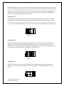
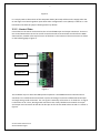
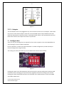
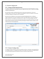
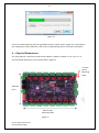
VORTEX 16
USER MANUAL
V1.3
2
Contents
1. - Safety Notes ...................................................................................................................................... 4
1.1 - Plug and Play Version.................................................................................................................. 4
1.1.1 - AC Power.............................................................................................................................. 4
1.1.2 - Opening Enclosure ............................................................................................................... 4
1.1.3 - Air Vents............................................................................................................................... 4
1.2 - Bare Board Version ..................................................................................................................... 4
1.2.1 - Providing Power ................................................................................................................... 4
2. - Installation ........................................................................................................................................ 5
2.1 – Plug and Play Version ................................................................................................................. 5
2.1.1 – Power .................................................................................................................................. 5
2.1.2 - Control Data ......................................................................................................................... 5
2.1.3 – Lights ................................................................................................................................... 5
2.2 - Bare Board Version ..................................................................................................................... 5
2.2.1 - Power and Links ................................................................................................................... 5
2.2.2 - Control Data ......................................................................................................................... 7
3. - Configuration .................................................................................................................................... 8
3.1 - On-board Configuration .............................................................................................................. 9
3.1.1 - DMX Address........................................................................................................................ 9
3.1.2 - Mode Settings ...................................................................................................................... 9
3.2 - Remote Configuration............................................................................................................... 10
3.2.1 - Remote Utility Requirements ............................................................................................ 10
3.2.2 - Remote Configuration........................................................................................................ 10
4. - Operation ........................................................................................................................................ 11
4.1 - Sending Data ............................................................................................................................. 11
4.1.1 - Termination........................................................................................................................ 11
5. - Firmware Upgrades......................................................................................................................... 12
5.1 - Physical Setup ........................................................................................................................... 12
5.2 - Obtaining New Firmware .......................................................................................................... 12
5.3 - Performing the Update ............................................................................................................. 12
6. – Physical Dimensions ....................................................................................................................... 13
7. - Troubleshooting .............................................................................................................................. 14
7.1 - LED Error Codes ........................................................................................................................ 14
7.2 - Other Issues .............................................................................................................................. 14
Vortex 16 User Manual V1.2
© 2013 Advatek Lights
3
7.2.1 - No Status/Power LEDs On.................................................................................................. 14
7.2.2 - Light Outputs Not As Expected .......................................................................................... 15
7.3 - Warranty and Service................................................................................................................ 15
Vortex 16 User Manual V1.2
© 2013 Advatek Lights
4
1. - Safety Notes
1.1 - Plug and Play Version
1.1.1 - AC Power
Inside the fully assembled enclosure there are high voltage hazards. Extreme care must be taken
when opening the enclosure as there are exposed high voltage terminals inside. The US
configuration uses a 110v/60Hz AC mains supply while the European/Australian configuration uses a
240V/50Hz AC mains supply.
1.1.2 - Opening Enclosure
The enclosure can easily be opened by removing the 6 stainless steel long-thread screws located
around the edge of the enclosure lid. The lid may be completely removed allowing full access to the
circuit board, wiring and power supply inside.
1.1.3 - Air Vents
The enclosure has two air vents located on the top end which allow the enclosure to equalize to a
stable running temperature. It is critical to ensure these vents are not blocked or obstructed by
anything while the controller is in operation. Anything restricting the flow of air out of the enclosure
may cause it to overheat and could damage internal components. The unit features internal
temperature regulation which ensures that the internal operating temperature will not rise above
78° centigrade. It is essential to operate the unit in a well ventilated area.
1.2 - Bare Board Version
The board comes shipped in an anti-static bag and has several static-sensitive components on it.
Appropriate anti-static measures should be observed when handling the board.
1.2.1 - Providing Power
Power to the strings is applied via the two power bank screw terminal connectors J1 and J2, located
on the left-hand edge of the board. They are both clearly marked on the PCB with the polarity and
the power bank number. Logic power for the onboard circuitry may also be supplied to the board
separately via the connector J3. Do not apply any power without first referring to section 2.2.1 for
details on how to correctly configure the boards various power options. Strings on channels 1-8 are
powered via power bank 1 and strings on channels 9-16 are powered via power bank 2. The voltage
on each bank can be anywhere between 5V and 30V DC and it is the user’s responsibility to ensure
that the power supply used matches the voltage of the lights they are using and can supply the
correct amount of current. The total maximum current per power bank is 30 Amps, giving the board
a total maximum current capacity of 60 Amps.
Vortex 16 User Manual V1.2
© 2013 Advatek Lights
5
2. - Installation
2.1 – Plug and Play Version
2.1.1 – Power
The plug and play version will already be setup to run off mains power using either a US or
Australian style AC power plug attached to the enclosure.
2.1.2 - Control Data
DMX data is connected via a straight through cat5e cable to the internal Vortex controller via the
two external female RJ45 sockets protruding out through the centre cable gland. One is for DMX
data in and the other is for DMX data out.
2.1.3 – Lights
Lights are connected to the internal Vortex controller via the 16 waterproof female pigtail sockets.
There are eight protruding through each of the side cable glands and each individual pigtail is
labelled with a channel number between 1 and 16. Simply plug your Advatek RGB light strings into
the mating sockets, screw up the shroud covers and you are done. It is recommended to screw the
covers all the way up to ensure connection is solid and reliable. If using any cable extensions, simply
plug these in line with the enclosure socket and the light strings. If using other lights then an
appropriate 4 pin male plug will need to be attached to mate with the enclosure sockets. The pin out
of the female sockets on the enclosure is shown below.
Pin 1 ( +VE)
Pin 4 (Blue)
Pin 3 (Green)
Front View
Pin 2 (Red)
Figure1
2.2 - Bare Board Version
2.2.1 - Power and Links
The Vortex has two split power banks with separate fuses. The board comes shipped from the
factory with 3AG 30A fast blow fuses for fuse 1 and fuse 2. The split banks allow two different
voltages to be used simultaneously. The voltage on each bank can be anywhere between 5V and 30V
DC. The total maximum current per power bank is 30A, while the total maximum current for any of
the 48 individual channels is 2A, and the total maximum current per each RGB output is 4A (each of
the 16 RGB outputs is protected by a 4A mini-blade fuse.)
Power is connected to the Vortex board power banks via pluggable screw terminal connectors J2
and J3, located on the right-hand edge of the board. They are both clearly marked on the PCB with
the polarity and the power bank number.
Vortex 16 User Manual V1.2
© 2013 Advatek Lights
6
Before connecting any power to the Vortex board, the power link options must be setup correctly to
ensure safe and proper power operation. There are two main power configuration links L1 and L2 on
the board, as shown below. L2 selects where the 5V VCC logic power for all the on board logic ICs is
derived from. There are three main jumper configurations and these are marked on the PCB as ‘A’,
‘B’ and ‘C’. The three configurations are as follows:
Configuration A:
Logic power is derived directly from either the bank 1 or bank 2 power input. In order to use this
configuration, the voltage being supplied to the corresponding power bank must be 5V DC +-10%.
Exceeding 5V or reversing polarity for the VCC logic will destroy the on-board logic ICs as there is no
protection. The L2 jumper should be in the ‘A’ or 1-2 position for this configuration as shown below:
A
B
C
Figure1
Configuration B:
Logic power is derived from the on board 5V regulator via one of the two main power banks. The
regulator can accept any input voltage between 6V and 30V DC. This option is best used when
powering either of the main power banks with a voltage greater than 5V DC. The L2 jumper should
be in the ‘B’ or 3-4 position for this configuration as shown below:
A
B
C
Figure 2
Configuration C:
Logic power is derived from the on board regulator by a separate power source altogether via
connector J4. The L2 jumper should be in the ‘C’ or 5-6 position for this configuration as shown
below:
A
Vortex 16 User Manual V1.2
© 2013 Advatek Lights
B
C
7
Figure 3
L1 is simply used to select which of the two power banks (B1 or B2) will be used to supply either the
5V VCC logic or on board regulator input when either configuration A or B (above) is used for L2. The
board will come with the jumper selecting bank 1 by default.
2.2.2 - Control Data
Control data to the Vortex is achieved via the on board DMX input and output connectors. There are
two vertical RJ45 sockets J6 and J7 as well as two horizontal screw terminals J5 and J8 for the DMX
data interface, located at the top left corner of the board. The location of these connectors is shown
on the following page in figure 4.
J8 DMX IN
J7 DMX IN
J6 DMX OUT
J5 DMX OUT
Figure 4
The hardware layer on which the DMX protocol operates is the RS485 electrical communications
standard. This is a differential transmission system consisting of a two wire differential twisted pair
and single wire ground connection. The +ve signal is commonly referred to as ‘A’ while the –ve signal
is referred to as ‘B’. The A, B and ground connections are clearly labelled on the PCB for the input
and output screw terminals J5 and J8. The data pin out for the two RJ45 sockets J6 and J7 is shown in
figure 5.
Vortex 16 User Manual V1.2
© 2013 Advatek Lights
8
Figure 5
2.2.3 – Outputs
The bare board version uses pluggable 4-way screw terminal connectors on all outputs. These allow
easy access to the channel outputs, with each connector RGB output clearly labelled on the PCB
silkscreen along with its common positive. Each RGB channel output is also protected by a 4A miniblade fuse to ensure the output driver FETs are protected.
3. - Configuration
There are only two settings that are required for the Vortex to operate. This is the DMX address to
start listening on and the mode of operation.
On the controller is a switch that selects between on- board configuration (via DIP switches) or
remote configuration using the utility.
This setting is the left most switch (1) on the “Mode” DIP switch as shown below:
Figure 6
Pushing this switch up to the ON position will set the board to remote configuration mode and will
remember and use settings given by the PC utility regardless of the other settings on the board.
Pushing the switch downwards activates the remainder of the mode switches as well as the DMX
start address DIP switch.
Vortex 16 User Manual V1.2
© 2013 Advatek Lights
9
3.1 - On-board Configuration
3.1.1 - DMX Address
The DMX address can be set to anything between 1 and 494 out of a possible 512 DMX addresses.
This is because the board requires 19 DMX channels to operate in the smallest profile mode (mode
1). Other modes require more channels and hence a lower starting address.
To set the start address you need to work out the 9 bit binary representation of the address you are
setting and set this on the DMX address DIP switch (least significant bit (1) is on the right hand side
of the switch as shown below in figure 7 (this conforms to the IT industry standard of representing
binary addresses.)
MSB (Binary 256)
LSB (Binary 1)
Figure 7
If you set an address that is too high for the mode you are in, the status LED will change to a slow
flash to indicate that either the mode or address is invalid.
3.1.2 - Mode Settings
There are 3 modes that the Vortex can operate in. They are:
Mode 1: 3 color channels (Red, Green and Blue) that control the color of all of the strings, followed
by 16 intensity channels to control the individual channel intensity of the set color. (Total of 19 DMX
channels).
Mode 2: Split bank 3 color channels (R,G,B for bank 1, followed by another R,G,B for bank 2), which
is then followed by the 16 intensity channels. (Total of 22 DMX channels).
Mode 3: 16 x R,G,B (or 48 individual channels). If using this for RGB control, consider it individual
colour control for each of the 16 channels; if using it for standard DC dimming, consider it 48
individual dimmer channels.
To set the mode manually on SW1, the far right switch (marked ‘4’ in figure 6 above) represents the
least significant bit. Switches 2, 3 and 4 are all used to select the modes in binary. For example,
turning on switch 4 will select mode 1, turning on switch 3 will select mode 2 and turning on both
switches 3 and 4 will select mode 3. (Same binary methodology described above for the DMX
address DIP switch).
Vortex 16 User Manual V1.2
© 2013 Advatek Lights
10
3.2 - Remote Configuration
3.2.1 - Remote Utility Requirements
For remote configuration the remote switch on the board must be set as described above in section
3. The board must then be connected to the PC via a DMX connection, which is achieved via an RDM
enabled USB->DMX adaptor.
Once the utility has been installed and the board is connected and powered on, click on the
“Settings” button to select the correct COM port (the COM port used by your adapter can be found
under Device Manager->Hardware Devices in Windows.)
Next click on the “USB Devices” tab to bring up the page for DMX based devices. Clicking on
“Search” will discover any Vortex controllers currently on the DMX network. It does this using the
RDM (remote device management) standard protocol. Figure 8 on the following page shows the
main screen after a search has been performed and two Vortex 16 controllers discovered. The table
provides useful information about the controller(s) including the model, nickname, firmware, serial
number and even current temperature.
Figure 8
3.2.2 - Remote Configuration
To configure the board remotely, select the controller from the list. Controllers can be identified by a
user settable nickname. It is advised that initially you only attach one controller to the DMX network
at a time and assign appropriate nicknames to each one for future simple reference.
Vortex 16 User Manual V1.2
© 2013 Advatek Lights
11
To configure the nickname, DMX start address or mode settings, simply double click on any
controller in the list to bring up its configuration box as shown in figure 9 below. This dialog box
allows you to easily set the start address, nickname and mode of the controller. It also allows you to
perform a firmware upgrade.
Figure 9
4. - Operation
4.1 - Sending Data
Data must be sent on a DMX512 network. This can be set-up with a PC using a USB to DMX512
(RS485) adaptor or using any other standalone type of DMX512 controller. If using a USB to DMX
adapter, please ensure it has RDM support. (We recommend using something like the Ultra DMX
RDM Pro from DMXking or the DMX USB Pro from Enttec.)
Ensure you send the control data valid for the configured start address and mode. Any data sent
outside the address range relevant to the controller's settings will be ignored.
Multiple Vortex controllers can operate off the same address range if you want them to perform
exactly the same operation.
Note that the red status LED will flash very fast when the board is receiving a valid DMX signal.
4.1.1 - Termination
It is recommended that the last controller in the DMX network chain be terminated by a 120 ohm
resistor across the A and B data lines to avoid any unwanted signal reflections. The Vortex 16 circuit
board has a built in termination jumper link L3 (see figure 10) which should be moved to the “On”
position to enable termination across the data lines.
Vortex 16 User Manual V1.2
© 2013 Advatek Lights
12
Termination Link L3
Figure 10
5. - Firmware Upgrades
The controller is capable of having its firmware upgraded (new software). An upgrade is typically
used to fix any bugs that may have been overlooked in previous revisions or to add new features.
5.1 - Physical Setup
One of the advantages of using the RDM protocol is that each controller is individually addressable.
This allows us to perform an upgrade to any controller on the DMX network without it needing to be
isolated from other devices on the network. The upgrade will take place on a PC so a USB to DMX
adaptor is required.
5.2 - Obtaining New Firmware
All firmware files can be downloaded from the Advatek Lights website, the latest version is available
at www.advateklights.com/resources
5.3 - Performing the Update
Ensure that the physical requirements described above are adhered to.
1. To perform an upgrade, simply find the controller on the DMX network using the utility and
double click on it to bring up the controller’s configuration box (as per section 3.2.1 and
3.2.2 above.) Click the “Update Firmware” button.
2. Locate the encrypted firmware hex file you downloaded on your local machine via the
browse button.
3. Click “Upgrade” to commence the upgrade
4. Observe the progress bar which indicates the data transfer progress (as shown in figure 11).
When finished, a dialog box will appear to confirm the download was completed
successfully.
Vortex 16 User Manual V1.2
© 2013 Advatek Lights
13
Figure 11
If there is something wrong with the upgraded firmware, repeat steps 1-4 again if it is still visible in
the configuration utility. Otherwise, refer to the troubleshooting section for further information.
6. – Physical Dimensions
The “Plug and Play” enclosure has dimensions 185mm x 160mm x 130mm or 7.4” x 6.4” x 5.2”.
The bare board dimensions are as shown below in figure 12.
4 x 3mm
(0.12”)
Mounting
Holes
120mmm
(4.8”)
170mm (6.8”)
Mounting Holes
Figure 12
Vortex 16 User Manual V1.2
© 2013 Advatek Lights
14
7. - Troubleshooting
Generally, troubleshooting requires looking at the LEDs on the controller. In the plug and play
version there is a high voltage power supply inside so extreme caution must be taken. In this case,
follow this procedure:
Unplug the power from the controller before removing the case
Apply power once the lid is removed and the controller is in a safe position
DO NOT TOUCH the inside components of the controller while power is applied, only look at
the LEDs. If you want to change a jumper/switch setting, power should be removed first.
Power down and reattach the lid as soon as you have finished troubleshooting.
7.1 - LED Error Codes
Please refer to the table below for specific error codes.
POWER LED (GREEN)
STATUS LED (RED)
ERROR CONDITION
SOLID
SLOW FLASHING
INVALID DMX START ADDRESS
OR MODE SETTING
SOLID
OFF
NO DMX DATA
OFF
OFF
NO POWER
Table 2
7.2 - Other Issues
7.2.1 - No Status/Power LEDs On
If you have a plug and play controller, ensure that the outlet you are plugged into is active. If so,
ensure that the jumper settings are configured for setting ‘A’ if the lights are of the 5v type or setting
‘B’ of the lights are between 6v-30v.
A
B
C
Board running at 5v (setting ‘A’)
A
B
C
Board running at greater than 5v (setting ‘B’)
If the jumpers are correct still, check that the main power banks fuses haven't blown.
If you have a bare board version and you have setup your own power supply, ensure that it is
supplying voltage correctly. If it is, ensure that the jumpers are set to the correct settings as
described in the “Installation” section. If they are still correct, ensure that the main power bank
fuses have not blown.
Vortex 16 User Manual V1.2
© 2013 Advatek Lights
15
7.2.2 - Light Outputs Not As Expected
If the lights are not turning on at all or are displaying colors you are not expecting, firstly check that
the DMX address and mode of the controller are both correctly set. Then check that the
device/software you are using to send the DMX is correctly configured and all wiring is plugged in.
Finally, ensure that none of the individual RGB channel output fuses are blown.
Failing that, check the status LEDs for more information and refer to section 6.1 “LED Error Codes”.
If there is no error indicated by the LEDs, check that your wiring of the lights is in accordance with
section 2.2.3 “Installing the Lights”.
7.3 - Warranty and Service
If the device fails to perform as expected, please read the troubleshooting area of this manual. If you
cannot solve the problem using that information, you can send an e-mail to
[email protected] for more assistance.
If we cannot solve your problem remotely, you may return it to us for warranty services.
The Vortex 16 bare board and “plug and play” controllers come with a 12 month warranty.
Vortex 16 User Manual V1.2
© 2013 Advatek Lights


![Hockey Canada Registry User Manual [Complete]](http://vs1.manualzilla.com/store/data/006861334_1-f3aefff99f86c1666505c30ddd463ccc-150x150.png)