1
VSCAN
VSCAN Manual
Manual
Edition:
Edition: November
November 2012
2012
Tel: +49 40 528 401 0
Fax: +49 40 528 401 99
Web: www.visionsystems.de
Support: faq.visionsystems.de
The software described in this manual is furnished under a license agreement and may
be used only in accordance with the terms of that agreement.
Copyright Notice
c 2009-2012 Vision Systems. All rights reserved. Reproduction without
Copyright permission is prohibited.
Trademarks
VScom is a registered trademark of Vision Systems GmbH. All other trademarks and
brands are property of their rightful owners.
Disclaimer
Vision Systems reserves the right to make changes and improvements to its product
without providing notice.
Vision Systems provides this document “as is”, without warranty of any kind, either
expressed or implied, including, but not limited to, its particular purpose. Vision Systems reserves the right to make improvements and/or changes to this manual, or to the
products and/or the programs described in this manual, at any time.
Information provided in this manual is intended to be accurate and reliable. However,
Vision Systems assumes no responsibility for its use, or for any infringements on the
rights of third parties that may result from its use.
This product might include unintentional technical or typographical errors. Changes are
periodically made to the information herein to correct such errors, and these changes
are incorporated into new editions of the publication.
Version 1.7
VSCAN Manual
2
Contents
Contents
1 Installation
1.1 USB CAN Device . . . . . . . . . . . . . . . . . . .
1.2 Serial CAN Device . . . . . . . . . . . . . . . . . .
1.3 PCI-CAN . . . . . . . . . . . . . . . . . . . . . . .
1.4 Network CAN Device . . . . . . . . . . . . . . . .
1.4.1 Operational Modes . . . . . . . . . . . . . .
1.4.2 Configuration Overview . . . . . . . . . . .
1.4.3 Webbrowser Server Configuration . . . . . .
1.4.4 Webbrowser Channel Configuration . . . .
1.4.5 Webbrowser Tools . . . . . . . . . . . . . .
1.4.6 Factory Settings . . . . . . . . . . . . . . .
1.5 Linux Installation (SocketCAN) . . . . . . . . . . .
1.6 General Information . . . . . . . . . . . . . . . . .
1.6.1 LED Status . . . . . . . . . . . . . . . . . .
1.6.2 Baud-rates and Handshake . . . . . . . . .
1.6.3 Pin-out of the 9 Pin D-Sub Connector . . .
1.6.4 Termination Resistors . . . . . . . . . . . .
1.6.5 Terminal Block Power (NET-CAN Devices)
2 Application Programming Interface
2.1 Introduction . . . . . . . . . . .
2.2 Functions . . . . . . . . . . . .
2.2.1 VSCAN Open . . . . .
2.2.2 VSCAN Close . . . . .
2.2.3 VSCAN Ioctl . . . . . .
2.2.4 VSCAN Read . . . . . .
2.2.5 VSCAN SetRcvEvent .
2.2.6 VSCAN Write . . . . .
2.2.7 VSCAN Flush . . . . .
2.2.8 VSCAN GetErrorString
2.3 Types and Structures . . . . .
2.3.1 VSCAN HANDLE . . .
2.3.2 VSCAN STATUS . . .
2.3.3 VSCAN API VERSION
2.3.4 VSCAN HWPARAM .
2.3.5 VSCAN MSG . . . . . .
2.3.6 VSCAN BTR . . . . . .
2.3.7 VSCAN CODE MASK
.
.
.
.
.
.
.
.
.
.
.
.
.
.
.
.
.
.
.
.
.
.
.
.
.
.
.
.
.
.
.
.
.
.
.
.
.
.
.
.
.
.
.
.
.
.
.
.
.
.
.
.
.
.
.
.
.
.
.
.
.
.
.
.
.
.
.
.
.
.
.
.
.
.
.
.
.
.
.
.
.
.
.
.
.
.
.
.
.
.
.
.
.
.
.
.
.
.
.
.
.
.
.
.
.
.
.
.
.
.
.
.
.
.
.
.
.
.
.
.
.
.
.
.
.
.
.
.
.
.
.
.
.
.
.
.
.
.
.
.
.
.
.
.
.
.
.
.
.
.
.
.
.
.
.
.
.
.
.
.
.
.
.
.
.
.
.
.
.
.
.
.
.
.
.
.
.
.
.
.
.
.
.
.
.
.
.
.
.
.
.
.
.
.
.
.
.
.
.
.
.
.
.
.
.
.
.
.
.
.
.
.
.
.
.
.
.
.
.
.
.
.
.
.
.
.
.
.
.
.
.
.
.
.
.
.
.
.
.
.
.
.
.
.
.
.
.
.
.
.
.
.
.
.
.
.
.
.
.
.
.
.
.
.
.
.
.
.
.
.
.
.
.
.
.
.
.
.
.
.
.
.
.
.
.
.
.
.
.
.
.
.
.
.
.
.
.
.
.
.
.
.
.
.
.
.
.
.
.
.
.
.
.
.
.
.
.
.
.
.
.
.
.
.
.
.
.
.
.
.
.
.
.
.
.
.
.
.
.
.
.
.
.
.
.
.
.
.
.
.
.
.
.
.
.
.
.
.
.
.
.
.
.
.
.
.
.
.
.
.
.
.
.
.
.
.
.
.
.
.
.
.
.
.
.
.
.
.
.
.
.
.
.
.
.
.
.
.
.
.
.
.
.
.
.
.
.
.
.
.
.
.
.
.
.
.
.
.
.
.
.
.
.
.
.
.
.
.
.
.
.
.
.
.
.
.
.
.
.
.
.
.
.
.
.
.
.
.
.
.
.
.
.
.
.
.
.
.
.
.
.
.
.
.
.
.
.
.
.
.
.
.
.
.
.
.
.
.
.
.
.
.
.
.
.
.
.
.
.
.
.
.
.
.
.
.
.
.
.
.
.
.
.
.
.
.
.
.
.
.
.
.
.
.
.
.
.
.
.
.
.
.
.
.
.
.
.
.
.
.
.
.
.
.
.
.
.
.
.
.
.
.
.
.
.
.
.
.
.
.
.
.
.
.
.
.
.
.
.
.
.
.
.
.
.
.
.
.
.
.
.
.
.
.
.
.
.
.
.
.
.
.
.
.
.
.
.
.
.
.
.
.
.
.
.
.
.
.
.
.
.
.
.
.
.
.
.
.
.
.
.
.
.
.
.
.
.
.
.
.
.
.
.
.
.
.
.
.
.
.
.
.
.
.
.
5
5
6
7
8
8
10
11
13
14
17
18
19
19
19
19
19
19
.
.
.
.
.
.
.
.
.
.
.
.
.
.
.
.
.
.
20
20
21
21
22
23
27
28
30
31
32
33
33
33
33
34
34
35
35
3 ASCII Command Set
36
3.1 Introduction . . . . . . . . . . . . . . . . . . . . . . . . . . . . . . . . . . . 36
Version 1.7
VSCAN Manual
3
Contents
3.2
Commands . . . . . . . . . . . . . . . . . . . . . . . . . .
3.2.1 Open the CAN Channel . . . . . . . . . . . . . . .
3.2.2 Close the CAN Channel . . . . . . . . . . . . . . .
3.2.3 Setup the Bus Timing (Standard) . . . . . . . . .
3.2.4 Setup the Bus Timing (Advanced) . . . . . . . . .
3.2.5 Transmitting a Standard Frame . . . . . . . . . . .
3.2.6 Transmitting a Standard Remote Request Frame .
3.2.7 Transmitting an Extended Frame . . . . . . . . . .
3.2.8 Transmitting an Extended Remote Request Frame
3.2.9 Set Time-Stamps . . . . . . . . . . . . . . . . . . .
3.2.10 Set Filter Mode . . . . . . . . . . . . . . . . . . . .
3.2.11 Set Acceptance Code and Mask Register . . . . . .
3.2.12 Get Status Flags . . . . . . . . . . . . . . . . . . .
3.2.13 Get Version Information . . . . . . . . . . . . . . .
3.2.14 Get Serial Number . . . . . . . . . . . . . . . . . .
3.2.15 Get Extra-Information . . . . . . . . . . . . . . . .
4 Tools
4.1 Firmware-Update . . . . . . . . .
4.2 Busmaster . . . . . . . . . . . . .
4.3 CANHacker . . . . . . . . . . . .
4.4 Wireshark . . . . . . . . . . . . .
4.5 CANopen . . . . . . . . . . . . .
4.5.1 Introduction . . . . . . .
4.5.2 Running Example . . . .
4.5.3 Compilation Instructions
4.6 Wrapper DLL System . . . . . .
4.7 ZOC . . . . . . . . . . . . . . . .
4.8 putty . . . . . . . . . . . . . . . .
4.9 vs can search . . . . . . . . . . .
4.10 LabVIEW . . . . . . . . . . . . .
4.10.1 Open CAN Channel . . .
4.10.2 Read CAN Frame . . . .
4.10.3 Write CAN Frame . . . .
.
.
.
.
.
.
.
.
.
.
.
.
.
.
.
.
.
.
.
.
.
.
.
.
.
.
.
.
.
.
.
.
.
.
.
.
.
.
.
.
.
.
.
.
.
.
.
.
.
.
.
.
.
.
.
.
.
.
.
.
.
.
.
.
.
.
.
.
.
.
.
.
.
.
.
.
.
.
.
.
5 Frequently Asked Questions
Version 1.7
.
.
.
.
.
.
.
.
.
.
.
.
.
.
.
.
.
.
.
.
.
.
.
.
.
.
.
.
.
.
.
.
.
.
.
.
.
.
.
.
.
.
.
.
.
.
.
.
.
.
.
.
.
.
.
.
.
.
.
.
.
.
.
.
.
.
.
.
.
.
.
.
.
.
.
.
.
.
.
.
.
.
.
.
.
.
.
.
.
.
.
.
.
.
.
.
.
.
.
.
.
.
.
.
.
.
.
.
.
.
.
.
.
.
.
.
.
.
.
.
.
.
.
.
.
.
.
.
.
.
.
.
.
.
.
.
.
.
.
.
.
.
.
.
.
.
.
.
.
.
.
.
.
.
.
.
.
.
.
.
.
.
.
.
.
.
.
.
.
.
.
.
.
.
.
.
.
.
.
.
.
.
.
.
.
.
.
.
.
.
.
.
.
.
.
.
.
.
.
.
.
.
.
.
.
.
.
.
.
.
.
.
.
.
.
.
.
.
.
.
.
.
.
.
.
.
.
.
.
.
.
.
.
.
.
.
.
.
.
.
.
.
.
.
.
.
.
.
.
.
.
.
.
.
.
.
.
.
.
.
.
.
.
.
.
.
.
.
.
.
.
.
.
.
.
.
.
.
.
.
.
.
.
.
.
.
.
.
37
37
37
37
38
39
39
40
40
41
41
41
42
42
42
43
.
.
.
.
.
.
.
.
.
.
.
.
.
.
.
.
.
.
.
.
.
.
.
.
.
.
.
.
.
.
.
.
.
.
.
.
.
.
.
.
.
.
.
.
.
.
.
.
.
.
.
.
.
.
.
.
.
.
.
.
.
.
.
.
.
.
.
.
.
.
.
.
.
.
.
.
.
.
.
.
.
.
.
.
.
.
.
.
.
.
.
.
.
.
.
.
.
.
.
.
.
.
.
.
.
.
.
.
.
.
.
.
.
.
.
.
.
.
.
.
.
.
.
.
.
.
.
.
.
.
.
.
.
.
.
.
.
.
.
.
.
.
.
.
44
44
44
44
45
47
47
47
48
50
51
51
52
53
53
54
55
56
VSCAN Manual
4
1
INSTALLATION
1 Installation
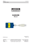
VSCAN devices support both Windows and Linux operating systems. The ASCII protocol is used to exchange data and control information with the devices and hence a
serial interface is required to enable the communication.
SER-CAN devices don’t usually need any driver installation and can be used directly
after plugging in. USB-CAN and PCI-CAN both require Windows driver installation
from the by-packed CD (modern Linux distributions often include those drivers by default, so no need to install the driver). NET-CAN has only Windows driver, but can be
used operating system independent without driver in TCP raw mode. Please read the
relevant installation instructions below for your particular device.
For the ease of use ASCII protocol is implemented in vs can api library with appropriate
API. Linux users can alternatively use SocketCAN driver, that also implements ASCII
protocol.
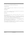
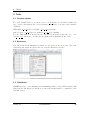
1.1 USB CAN Device
Use the USB driver from the directory USB-CAN\Driver” on the product CD or down”
load it from our company website www.visionsystems.de. If you’ve done this, you could
plug in the adapter in an USB port of your choice. When you will be asked for the
driver, you must choose the location of the driver files. The device will be registered and
you can use the COM port for your further work (see Figure 1).
Figure 1: Device Manager
To get a better performance and set every standard baudrate as an alias for 3Mbit (except 115200), you must call the script regmodify.vbs” with the desired COM port like
”
this: cscript regmodify.vbs COM7”. The script must be executed with administrative
”
privileges. Please disconnect the device from the system for about 5 seconds after this
step and connect again.
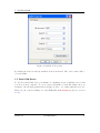
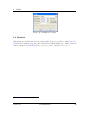
Then you can open the COM port of the USB-CAN with any standard baudrate1 (see
Figure 2).
1
300, 600, 1200, 2400, 4800, 9600, 19200, 38400, 57600, 230400, 460800, 921600
Version 1.7
VSCAN Manual
5
1
INSTALLATION
Figure 2: COM Port Properties
For Linux the driver is already available in modern kernel. The device name will be
/dev/ttyUSBx.
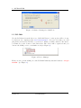
1.2 Serial CAN Device
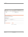
To use the serial CAN device you mustn’t do anything except for finding a free serial
port in your host computer. To get a better performance you should change the port
settings to the following parameters (see Figure 3). Reboot to ensure that they were set.
Then you can open the COM port of the SER-CAN with 115200 bps (refer to Section
1.6.2).
Version 1.7
VSCAN Manual
6
1
INSTALLATION
Figure 3: Advanced Settings for COM Port
1.3 PCI-CAN
Use the PCI driver from the directory PCI-CAN\Driver” on the product CD or down”
load it from our company website www.visionsystems.de. If you’ve done this, you could
plug in the card in a free PCI slot of your choice. When you will be asked for the driver,
you must choose the location of the driver files. The device will be registered and you
can use the COM port for your further work (see Figure 4).
Figure 4: Device Manager
Then you can open the COM port of the PCI-CAN with any standard baudrate - except
115200 - (see Figure 2).
Version 1.7
VSCAN Manual
7
1
INSTALLATION
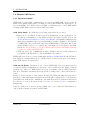
1.4 Network CAN Device
1.4.1 Operational Modes
NET-CAN provides CAN communication over network. NET-CAN can act either as
CAN Server (CAN frames will be exchanged between NET-CAN and application connected via COM port or TCP socket) or as CAN over IP Router (two or more NET-CANs
exchange CAN frames between various CAN networks)
CAN Server Mode For CAN Server following approaches are provided:
• Driver mode: in this mode the network is transparent for the application. To
use this mode installation of the Windows driver is required (please refer to the
”NetCom Wireless Serial Device Server User Manual” for installation instructions).
After driver installation the new virtual COM port will be available to the system,
so NET-CAN can be used in the same way as SER-CAN or USB-CAN. Due to the
virtual COM port protocol overhead the performance is lower than by the TCP
raw mode. You don’t have to set the baudrate and hardware handshake explicitly
- it’s fixed to 3Mbit and RTS/CTS.
• TCP raw mode: the communication will be handled directly via IP address and
port number. In this mode no driver installation is required.
NET-CAN devices can be operated with either ASCII or VSCAN API. For the API there
is no difference whether Driver mode or TCP raw mode is used, but due to performance
issues TCP raw mode is preferable.
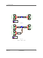
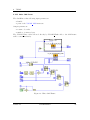
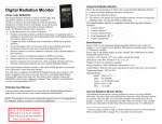
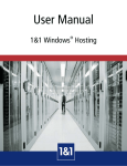
CAN over IP Router In this mode two or more NET-CAN devices are interconnected
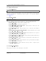
to enable seamless communication between two or more CAN networks. Figure 5a shows
the first case, where two NET-CAN devices act as a tunnel between CAN Network A
and B, so all frames sent inside Network A will be transported to Network B and vice
versa.
Figure 5b shows extension of the tunnel. In this case additional CAN network can be
attached, so that CAN frames sent inside Network A will be transported to both B and C,
but CAN Network B and C communicate only with Network A, so frames from Network
B could not be seen by Network B and vice versa. See Section 1.4.4 for configuration
instructions.
CAN Acceptance Code and Acceptance Mask can be set to filter the CAN frames, so
only dedicated frames are passed via TCP link.
Version 1.7
VSCAN Manual
8
1
INSTALLATION
Node 1
CAN
Network B
Node 1
Internet
NET-CAN Intranet NET-CAN
Node n
CAN
Network A
Node n
Legend
Ethernet link
CAN link
(a) Tunnel
Node 1
CAN
Network B
Node 1
NET-CAN
Internet
Intranet
NET-CAN
Node n
Internet
Intranet
Node n
Node 1
CAN
Network C
CAN
Network A
NET-CAN
Node n
Legend
Ethernet link
CAN link
(b) 1-to-n
Figure 5: CAN over IP
Version 1.7
VSCAN Manual
9
1
INSTALLATION
1.4.2 Configuration Overview
NET-CAN device can be configured in following ways:
• via web interface
• via Telnet
• via NetCom Manager
For Telnet and NetCom Manager configuration refer to the ”NetCom Wireless Serial
Device Server User Manual”.
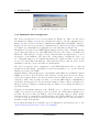
Open your Webbrowser for the web interface configuration. Type the address of the
NET-CAN server in the address line . Type the standard address http://192.168.254.254”
”
for example. You may do this on any operating system you prefer.
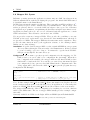
Figure 6: Web Interface for Configuration
The NET-CAN welcomes you with its “Home” screen (see Figure 6). Click on the icon
for your desired option. In many menus you’ll see a blue question mark. This is a
symbol for help. Click it to get a short explanation, informing about the function of this
parameter. Some other settings require a reboot to save and activate them. Whenever
this situation occurs, the NET-CAN requests for a Reboot (see Figure 7).
You can instantly reboot or do that later when the configuration is finished.
Version 1.7
VSCAN Manual
10
1
INSTALLATION
Figure 7: Web Interface Request to Reboot
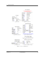
1.4.3 Webbrowser Server Configuration
The Server Configuration is a very long menu (see Figure 8). There is basic server
information (see Figure 8a), the server parameters related to the IP-configuration (see
Figure 8b), the section for wireless communication (NET-CAN 120 WLAN only) (see
Figure 8c), the section for encrypted communication (see Figure 8d), Password settings
(see Figure 8e), and finally the configuration for date and time (see Figure 8f).
Information about the selected NET-CAN is displayed as Server Info. Starting with the
Server Type, this is the model of the NET-CAN, followed by the version of Software and
Hardware. This will give a rough overview, which features are implemented, or need
an upgrade of the firmware. The Serial Nr. is important to identify the device you
are configuring right now. For further information the UpTime is listed. Contact and
Location are user-defined information. They may later help to find the device in the
installation, and the person responsible for management.
The Server Parameter allow configuration of the NET-CANs name and of course all
parameters in IP-settings. Generally it is used as information, e.g. in the NetCom
Manager program or in SNMP.
Manual changes of IP parameters are only available with DHCP set as Disabled. When
DHCP is not used, enter IP Address and Netmask, as well as the Broadcast address.
Gateway is required, if there are Routers in the network. DNS is used to access other
stations by name. The ConfigPort is used to access the NET-CAN for administration
via Telnet. It is suggested to use the standard value for Telnet, TCP port number 23.
However it may be changed for different purposes. This does not change the function of
the Telnet menus.
KeepAlive is an intrinsic function of the TCP/IP protocol. If used it causes network
traffic, but connection problems are detected earlier. In a LAN this is usually not a
problem. However, if used via DialUp connections this may cause problems. If this
functions is used, you must define an interval in seconds. NET-CAN has a better chance
to react on network problems, or failed hosts. Even dropping an old connection may be
useful in certain environments.
For detailed information about further Server Configuration options please refer to the
”NetCom Wireless Serial Device Server User Manual”.
Version 1.7
VSCAN Manual
11
1
INSTALLATION
(a) Server Info
(b) Server Parameter
(c) Wireless Parameter
(d) OpenVPN Parameter
(e) Authentication
(f) Date and Time Settings
Figure 8: Server Configuration
Version 1.7
VSCAN Manual
12
1
INSTALLATION
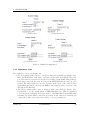
1.4.4 Webbrowser Channel Configuration
NET-CAN can be operated in following modes (see Figure 9):
• Driver Mode - Only very few parameters have a function in Driver Mode (see
Figure 9a). NET-CAN is operating as a Server. It accepts two connections per
CAN channel. One connection is used to transmit the serial data, this is the
TCP Port(Data). And the other is used to transmit control information, TCP
Port(Control). This control connection is mostly used to request the status of the
virtual serial port. Software may intend to change serial parameters like baudrate
or parity, such requests are honoured. However they are ignored, because the serial
parameters are fixed in the NET-CAN. The NET-CAN can check if the connected
Client is still alive. This may be done, when a second Client wants to establish a
connection (On Connect). It may also be done in regular intervals (Polling).
• TCP Raw Server - As TCP Raw Server NET-CAN operates very simple (see Figure
9b). It only waits for incoming data connections in Raw IP mode. As with the
Driver Mode only the data connection is defined. You can connect multiple times
to the NET-CAN also from different machines.
• CAN Bridge Server - Configures server side of the CAN over IP Router functionality. In this mode NET-CAN waits for incoming connections. Max. Clients value
defines how many CAN Bridge Clients can connect to the server. CAN Speed sets
the appropriate baudrate of the attached CAN network. Acceptance Code and
Mask allow CAN frame filtering so only the dedicated frames pass over TCP link
(See Figure 9c).
• CAN Bridge Client - Configures client side of the CAN over IP Router functionality.
In this mode NET-CAN connects to the other NET-CAN in the CAN Bridge Server
Mode. CAN Speed sets the appropriate baudrate of the attached CAN network.
Acceptance Code and Mask allow CAN frame filtering so only the dedicated frames
pass over TCP link (See Figure 9d).
Version 1.7
VSCAN Manual
13
1
INSTALLATION
(a) Driver Mode
(b) TCP Raw Server
(c) CAN Bridge Server
(d) CAN Bridge Client
Figure 9: Channel Configuration
1.4.5 Webbrowser Tools
The available tools are (see Figure 10):
• The Ping utility will be used to check if a station is available (see Figure 10a).
Enter the IP-Address or the name of a station in the field, and click the Ping button. The network connection is checked by sending certain ICMP data packages.
If the target responds, the network between the NET-CAN and the target is operational. The time required for an echo depends on the speed of the network. In a
typical Ethernet this is only very few Milliseconds, while it can be several seconds
throughout the Internet.
• The Netstat utility will be used to monitor TCP connections (see Figure 10b).
Use Netstat to see the actual status of NET-CAN IP Ports. This is a standard
tool for network debugging. A Foreign Address of 0.0.0.0 is listed when NET-CAN
is waiting for an incoming connection (LISTEN). If the value is not 0.0.0.0, the
connection is either active (ESTABLISHED) or closed (TIMEWAIT).
Version 1.7
VSCAN Manual
14
1
INSTALLATION
• The Firmware Update option is used to update the firmware (see Figure 10c). To
upload a new version of the firmware, put the name of the file in the field. Your
Webbrowser may allow to search for the file. Click on the “Update” button. While
loading the file is checked. If it is valid, it is stored in the Flash Memory. When
the upload is finished, NET-CAN will Reboot.
• The Saving of Configuration to / Loading from a file option will be used to manage
NET-CAN configuration (see Figure 10d). It is possible to save the actual configuration to a text file. Of course it is also possible to load the saved configuration
into a NET-CAN.
• The Syslog option will be used to send logging information to the syslog facility
(see Figure 10e). Syslogging requires a server the information is sent to. Facility
allows to select the data sent to that server.
• The DebugLog option will be used to show logging information via TCP connection
(see Figure 10e). For this kind of logging the NET-CAN behaves as the server.
Open a TCP connection to the configured port, and receive all information generated.
Version 1.7
VSCAN Manual
15
1
INSTALLATION
(a) Ping
(b) Netstat
(c) Firmware Update
(d) Configuration File
(e) Syslog
Figure 10: Tools
Version 1.7
VSCAN Manual
16
1
INSTALLATION
1.4.6 Factory Settings
NET-CAN provides DIP-switches to set setting back to their defaults. Please refer to the
Table 1 for possible switches settings. After setting the settings back, the DIP-switches
must be returned to the CAN Operation” position.
”
Operation Mode
CAN Operation
Factory Settings
S1
OFF
OFF
S2
OFF
OFF
S3
OFF
OFF
S4
OFF
ON
Table 1: Switches
Version 1.7
VSCAN Manual
17
1
INSTALLATION
1.5 Linux Installation (SocketCAN)
SocketCAN2 is a set of open source CAN drivers and a networking stack contributed
by Volkswagen Research to the Linux kernel. As of Linux kernel 2.6.38 ASCII protocol
(slcan) will be also supported. To use it you’ll first need to install can-utils from project’s
git3 repository4 .
For USB CAN device, that is attached to /dev/ttyUSB0 device, execute following
commands:
stty -F /dev/ttyUSB0 ispeed 3000000 ospeed 3000000
slcan_attach -o -s8 /dev/ttyUSB0
slcand ttyUSB0
ifconfig slcan0 up
You’ll get your USB CAN operated at 1MBit/s, with candump and cansend you can
make first send/receive tests.
For Network CAN devices (NET-CAN) you’ll first need to create a symbolic link to it
via socat. Assume your NET-CAN has following IP address: 192.168.254.254. So the
needed commands are:
socat pty,link=/dev/netcan0,raw tcp:192.168.254.254:2001&
slcan_attach -o -s8 /dev/netcan0
slcand netcan0
ifconfig slcan0 up
2
http://en.wikipedia.org/wiki/Socketcan
Git
4
SocketCAN git repository
3
Version 1.7
VSCAN Manual
18
1
INSTALLATION
1.6 General Information
1.6.1 LED Status
The red error LED lights up, when a bus error occur. And the green data LED is on,
when a frame was sent to or received from the bus.
1.6.2 Baud-rates and Handshake
Ensure you’ve set the handshake to RTS/CTS (hardware) when you open the port!
Device
USB-CAN
NET-CAN
SER-CAN
PCI-CAN
Baud-rate
3 Mbit
3 Mbit
115200 kbit
3 Mbit
Handshake
RTS/CTS
RTS/CTS
RTS/CTS
RTS/CTS
1.6.3 Pin-out of the 9 Pin D-Sub Connector
Pin
1
2
3
4
5
6
7
8
9
Signal
CAN V+
CAN L
CAN GND
GND
CAN H
CAN V+
Description
100mA @ 5V to drive the transceiver or optocouplers (optional)
CAN L bus line (dominant level is low)
CAN ground
reserved
reserved
ground (optional)
CAN H bus line (dominant level is high)
reserved
like pin 1
1.6.4 Termination Resistors
The USB CAN, serial CAN and network CAN devices have no termination resistors
inside. It’s up to you to choose the correct combination and values for your topology.
1.6.5 Terminal Block Power (NET-CAN Devices)
The Terminal Block power connector receives positive voltage on the right (V+) pin.
The center (V-) pin connector is negative, which is connected to GND and the case.
GND is the same as Field GND (FG), so the standard adapter does not connect to this
pin.
Version 1.7
VSCAN Manual
19
2
APPLICATION PROGRAMMING INTERFACE
2 Application Programming Interface
2.1 Introduction
The Application Programming Interface (API) gives you the right tools to use all of
the functions that the VSCAN devices provide. It will make your life much easier to
build your own CAN controlling software with these functions, than to implement your
application directly on top of the ASCII protocol.
For Windows, the only thing you must do, is to copy the dynamic link library (vs can api.dll),
the linker input file (vs can api.lib) and header file (vs can api.h) into your project directory. Include the header in your source code and add the vs can api.lib to your project
configuration.
For Linux, you must copy the library (libvs can api.so) to your global libraries path
and add it to your compilation parameters. You must also include the header file
(vs can api.h) in your source file.
For other operating systems like MacOS you’ll have to implement ASCII protocol yourself.
All functions and data structures are explained in the next sub-sections.
You can also use our API library with programming languages other than C/C++. To do
so you’ll have to learn how to import the functions from our library to your application.
To ease this task wrapper for following programming languages will be provided together
with VSCAN API x y z.zip under Wrapper\Languages:
• C#
• VisualBasic.NET
• Delphi
• LabVIEW
• more to come
Version 1.7
VSCAN Manual
20
2
APPLICATION PROGRAMMING INTERFACE
2.2 Functions
2.2.1 VSCAN Open
The VSCAN_Open function opens the CAN channel.
VSCAN_HANDLE VSCAN_Open(CHAR *SerialNrORComPortORNet, DWORD Mode);
Parameters:
SerialNrORComPortORNet
[in] A char pointer with one of the following values.
• VSCAN FIRST FOUND - the first device found will be opened
• Serial number of the specific device
• COM port or CAN name where the device is located
• IP address and port number of the device
Mode
[in] The mode in which the CAN channel shall be opened.
• VSCAN MODE NORMAL - the normal operation mode
• VSCAN MODE LISTEN ONLY - the listen only mode, in which no CAN interaction will be done from the controller
• VSCAN MODE SELF RECEPTION - the self reception mode, in which the device receives also the frames that it sends. The firmware version must be 1.4 or
greater and the DLL version 1.6 or greater.
Examples:
handle = VSCAN_Open(VSCAN_FIRST_FOUND, VSCAN_MODE_NORMAL);
handle = VSCAN_Open("123456", VSCAN_MODE_LISTEN_ONLY);
// Windows, Linux
// Windows, Linux
handle = VSCAN_Open("COM3", VSCAN_MODE_NORMAL);
// Windows, WinCE
handle = VSCAN_Open("/dev/ttyUSB0", VSCAN_MODE_NORMAL);
// Linux
handle = VSCAN_Open("/dev/can0", VSCAN_MODE_LISTEN_ONLY);
// Linux on Alena (CAN on local b
handle = VSCAN_Open("192.168.254.254:2001", VSCAN_MODE_SELF_RECEPTION);
// Windows, WinCE, Linux
Version 1.7
VSCAN Manual
21
2
APPLICATION PROGRAMMING INTERFACE
2.2.2 VSCAN Close
The VSCAN_Close function will close the CAN channel.
VSCAN_STATUS VSCAN_Close(VSCAN_HANDLE Handle);
Parameters:
Handle
[in] The handle of the CAN device, which shall be closed.
Example:
status = VSCAN_Close(handle);
Version 1.7
VSCAN Manual
22
2
APPLICATION PROGRAMMING INTERFACE
2.2.3 VSCAN Ioctl
You can get and set special information and commands of the CAN device with the
VSCAN_Ioctl function.
VSCAN_STATUS VSCAN_Ioctl(VSCAN_HANDLE Handle, DWORD Ioctl, VOID *Param);
Parameters:
Handle
[in] The handle of the CAN device, which should be used.
Ioctl
[in] Tells the function which of the following ioctl should be called.
Param
[in, out] A pointer to the data for the ioctls which are listed below.
VSCAN IOCTL SET DEBUG
You can set the debug verbosity with this ioctl. The higher the debug level the more
debug information you get. The VSCAN_HANDLE can be NULL.
Possible debug levels are:
• VSCAN DEBUG NONE (no debug information)
• VSCAN DEBUG LOW (errors from the VSCAN API)
• VSCAN DEBUG MID (information from the VSCAN API)
• VSCAN DEBUG HIGH (errors from system functions)
Example:
status = VSCAN_Ioctl(NULL, VSCAN_IOCTL_SET_DEBUG, VSCAN_DEBUG_HIGH);
VSCAN IOCTL SET DEBUG MODE
You can set the debug mode with this ioctl. It is possible to log the error to the
standard error console output (default value) or to save it in a log file. The log file will
be saved in the directory from which your application is running and will be named
vs can api.log”. The VSCAN_HANDLE can be NULL.
”
The debug mode defines are:
• VSCAN DEBUG MODE CONSOLE
• VSCAN DEBUG MODE FILE
Example:
status = VSCAN_Ioctl(NULL, VSCAN_IOCTL_SET_DEBUG_MODE, VSCAN_DEBUG_MODE_FILE);
Version 1.7
VSCAN Manual
23
2
APPLICATION PROGRAMMING INTERFACE
VSCAN IOCTL GET API VERSION
You can request the API version number with this ioctl. Therefore you must commit
a pointer of the type VSCAN API VERSION to the function. The DLL version must
be 1.6 or greater.
Example:
status = VSCAN_Ioctl(handle, VSCAN_IOCTL_GET_API_VERSION, &version);
VSCAN IOCTL GET HWPARAM
This ioctl gives you the possibility to get the hardware parameters (serial number,
hardware and software version) of the device. Therefore you must commit a pointer of
the type VSCAN HWPARAM to the function.
Example:
status = VSCAN_Ioctl(handle, VSCAN_IOCTL_GET_HWPARAM, &hwparam);
VSCAN IOCTL SET SPEED
With this ioctl you can set the speed of your CAN device. The following speed values
are supported:
• VSCAN SPEED 1M
• VSCAN SPEED 800K
• VSCAN SPEED 500K
• VSCAN SPEED 250K
• VSCAN SPEED 125K
• VSCAN SPEED 100K
• VSCAN SPEED 50K
• VSCAN SPEED 20K
Example:
status = VSCAN_Ioctl(handle, VSCAN_IOCTL_SET_SPEED, VSCAN_SPEED_1M);
VSCAN IOCTL SET BTR
This ioctl gives you the possibility to configure the speed registers manually (bus
timing registers). Therefore you must commit a structure from the type VSCAN BTR.
For more information on this registers, please take a look at the SJA1000 datasheet from
NXP Semiconductors or at the following website: www.port.de
Example:
VSCAN_BTR btr = { .Btr0 = 0x00, .Btr1 = 0x14 }; // for 1Mb/s
status = VSCAN_Ioctl(handle, VSCAN_IOCTL_SET_BTR, &btr);
Version 1.7
VSCAN Manual
24
2
APPLICATION PROGRAMMING INTERFACE
VSCAN IOCTL SET FILTER MODE
This ioctl let you set the desired filter mode for the acceptance code and mask. You
can switch between single and dual filter mode. For more informations, please take a
look at the SJA1000 datasheet from NXP Semiconductors. The firmware version must
be 1.4 or greater and the DLL version 1.6 or greater.
Example:
status = VSCAN_Ioctl(handle, VSCAN_IOCTL_SET_FILTER_MODE, VSCAN_FILTER_MODE_DUAL);
VSCAN IOCTL SET ACC CODE MASK
You can set the acceptance code and acceptance mask register with this ioctl. This
gives you the possibility to filter for special frame types you want to receive. Therefore
you must commit a structure from the type VSCAN CODE MASK. The VSCAN devices
work in single filter mode. For more information on this specific registers, please take a
look at the SJA1000 datasheet from NXP Semiconductors.
Example:
VSCAN_CODE_MASK codeMask;
// will receive the ids between 0x300 and 0x3ff
codeMask.Code = 0x6000;
codeMask.Mask = 0x1ff0;
status = VSCAN_Ioctl(handle, VSCAN_IOCTL_SET_ACC_CODE_MASK, &codeMask);
// receive all frames on the CAN bus (default)
codeMask.Code = VSCAN_IOCTL_ACC_CODE_ALL;
codeMask.Mask = VSCAN_IOCTL_ACC_MASK_ALL;
status = VSCAN_Ioctl(handle, VSCAN_IOCTL_SET_ACC_CODE_MASK, &codeMask);
VSCAN IOCTL GET FLAGS
To get extended status and error flags use this ioctl. Commit a DWORD(32bit)
pointer as the Param argument. The bit flags and their equivalent macro names are:
• Bit 0: VSCAN IOCTL FLAG RX FIFO FULL
• Bit 1: VSCAN IOCTL FLAG TX FIFO FULL
• Bit 2: VSCAN IOCTL FLAG ERR WARNING
• Bit 3: VSCAN IOCTL FLAG DATA OVERRUN
• Bit 4: VSCAN IOCTL FLAG UNUSED
• Bit 5: VSCAN IOCTL FLAG ERR PASSIVE
• Bit 6: VSCAN IOCTL FLAG ARBIT LOST
• Bit 7: VSCAN IOCTL FLAG BUS ERROR
Version 1.7
VSCAN Manual
25
2
APPLICATION PROGRAMMING INTERFACE
Take a look at the SJA1000 datasheet from NXP Semiconductors, if you want more
information on what’s behind bit 2 to 7.
Example:
DWORD flags;
status = VSCAN_Ioctl(handle, VSCAN_IOCTL_GET_FLAGS, &flags);
VSCAN IOCTL SET TIMESTAMP
You can set on and off the time-stamp functionality with this ioctl. If you switch it on,
every received frame will have a valid time-stamp value in the VSCAN MSG structure.
The time base is in milliseconds and will be overrun after 60 seconds (timestamps between
0-60000ms).
Example:
status = VSCAN_Ioctl(handle, VSCAN_IOCTL_SET_TIMESTAMP, VSCAN_TIMESTAMP_ON);
VSCAN IOCTL SET BLOCKING READ
This ioctl will set theVSCAN Read function to blocking mode (default is unblock).
Example:
status = VSCAN_Ioctl(handle, VSCAN_IOCTL_SET_BLOCKING_READ, VSCAN_IOCTL_ON);
Version 1.7
VSCAN Manual
26
2
APPLICATION PROGRAMMING INTERFACE
2.2.4 VSCAN Read
To read one or more CAN frames from the CAN bus, you must use the VSCAN_Read
function. The read mode of this function is set to non-blocking mode per default. This
means that VSCAN_Read will return immediately - even when there are no frames at the
moment. To make the VSCAN_Read blocking, use the ioctlVSCAN IOCTL SET BLOCKING READ
- then it will return only if frames were received.
VSCAN_STATUS VSCAN_Read(VSCAN_HANDLE Handle, VSCAN_MSG *Buf, DWORD Size, DWORD *Read);
Parameters:
Handle
[in] The handle of the CAN device, which should be used.
Buf
[in] A pointer to one element or an array of the structure VSCAN MSG.
Size
[in] The number of the array elements in Buf.
*Read
[out] A pointer to a DWORD that will receive the real number of the frames read.
Example:
VSCAN_MSG msgs[10];
DWORD read;
status = VSCAN_Read(handle, msgs, 10, &read);
Version 1.7
VSCAN Manual
27
2
APPLICATION PROGRAMMING INTERFACE
2.2.5 VSCAN SetRcvEvent
With the VSCAN_SetRcvEvent function you can set an event which will be set when
a frame arrives. There are different versions for Windows and Linux. The DLL version
must be 1.6 or greater.
// Windows Prototype:
VSCAN_STATUS VSCAN_SetRcvEvent(VSCAN_HANDLE Handle, HANDLE Event);
// Linux Prototype:
VSCAN_STATUS VSCAN_SetRcvEvent(VSCAN_HANDLE Handle, sem_t *Event);
Parameters:
Handle
[in] The handle of the CAN device, which should be used.
Event
[in] In Windows an event handle of the type HANDLE and in Linux a pointer to the
sem_t union.
Windows Example:
// don’t forget your own error handling for the API and system functions
// for further informations on these functions take a look at the MSDN
HANDLE hEvent;
DWORD dwRetCode;
hEvent = CreateEvent(NULL, FALSE, FALSE, NULL);
VSCAN_SetRcvEvent(handle, hEvent);
dwRetCode = WaitForSingleObject(hEvent, INFINITE);
switch(dwRetCode)
{
case WAIT_OBJECT_O :
// a CAN frame arrived
break;
default:
// probe for error
}
CloseHandle(hEvent);
Version 1.7
VSCAN Manual
28
2
APPLICATION PROGRAMMING INTERFACE
Linux Example:
// don’t forget your own error handling for the API and system functions
// take also a look at sem_trywait, sem_timedwait and the rest of the sem_* functions
sem_t sem;
int retCode;
retCode = sem_init(&sem, 0, 0);
VSCAN_SetRcvEvent(handle, &sem);
retCode = sem_wait(&sem);
// a CAN frame arrived
retCode = sem_destroy(&sem);
Version 1.7
VSCAN Manual
29
2
APPLICATION PROGRAMMING INTERFACE
2.2.6 VSCAN Write
With the VSCAN_Write function you can write one or more frames to the CAN bus.
The frames will be buffered and send out after some time - this time can grow up to one
time slice of the scheduler (Windows = ˜16ms and Linux = ˜10ms). If you want to send
the frames immediately, you must call the functionVSCAN Flush.
VSCAN_STATUS VSCAN_Write(VSCAN_HANDLE Handle, VSCAN_MSG *Buf, DWORD Size, DWORD *Written);
Parameters:
Handle
[in] The handle of the CAN device, which should be used.
Buf
[in] A pointer to one element or an array of the structure VSCAN MSG.
Size
[in] The number of the array elements in Buf.
*Written
[out] A pointer to a DWORD that will receive the number of frames written.
Example:
VSCAN_MSG msgs[10];
DWORD written;
msgs[0].Flags = VSCAN_FLAGS_EXTENDED;
msgs[0].Id = 100;
msgs[0].Size = 1;
msgs[0].Data[0] = 0x1B;
// we will send ten frames with the same data
// to the ids 100-109
for (i = 1; i < 10; i++)
{
memcpy(msgs + i, &msgs[0], sizeof(msgs[0]));
msgs[i].Id++;
}
status = VSCAN_Write(handle, msgs, 10, &written);
Version 1.7
VSCAN Manual
30
2
APPLICATION PROGRAMMING INTERFACE
2.2.7 VSCAN Flush
The VSCAN_Flush function will send all frames immediately out to the CAN bus.
VSCAN_STATUS VSCAN_Flush(VSCAN_HANDLE Handle);
Parameters:
Handle
[in] The handle of the CAN device, whose data should be flushed.
Example:
status = VSCAN_Flush(handle);
Version 1.7
VSCAN Manual
31
2
APPLICATION PROGRAMMING INTERFACE
2.2.8 VSCAN GetErrorString
The VSCAN_GetErrorString function retrieves the associated human readable error
string.
VOID VSCAN_GetErrorString(VSCAN_STATUS Status, CHAR *String, DWORD MaxLen);
Parameters:
Status
[in] The status for which the error string should be retrieved.
String
[out] A pointer of a string array which will receive the error string.
MaxLen
[in] The maximum possible length of the error string (without the terminating zero).
Example:
VSCAN_STATUS status = VSCAN_ERR_NO_DEVICE_FOUND;
char string[33];
VSCAN_GetErrorString(status, string, 32);
printf(string);
Version 1.7
VSCAN Manual
32
2
APPLICATION PROGRAMMING INTERFACE
2.3 Types and Structures
2.3.1 VSCAN HANDLE
typedef int VSCAN_HANDLE;
This type definition holds the handle of an opened CAN channel. In this case the
value is greater than zero. Otherwise the value is equal to one of the type definition
VSCAN STATUS.
2.3.2 VSCAN STATUS
typedef int VSCAN_STATUS;
The type definition VSCAN_STATUS can have one of the following status value.
• VSCAN ERR OK - indicates that everything is okay
• VSCAN ERR ERR - indicates a general error
• VSCAN ERR NO DEVICE FOUND - indicates that no CAN device was
found with the specific functions
• VSCAN ERR SUBAPI - indicates that an error occurred in a subordinated
library
• VSCAN ERR NOT ENOUGH MEMORY - indicates that there is not enough
memory to complete the function
• VSCAN ERR NO ELEMENT FOUND - indicates that there is no requested
element available (e.g. from an input buffer)
• VSCAN ERR INVALID HANDLE - indicates that the handle which is used
is not valid (e.g. CAN channel closed)
• VSCAN ERR IOCTL - indicates that an ioctl request failed; ensure that you’ve
used the right parameter values
• VSCAN ERR MUTEX - indicates that there was a problem with a used mutex
in the VSCAN API (e.g. timeout)
• VSCAN ERR CMD - indicates that there was a problem to complete a given
command on the CAN device
2.3.3 VSCAN API VERSION
This structure holds the version information of the API.
Version 1.7
VSCAN Manual
33
2
APPLICATION PROGRAMMING INTERFACE
typedef struct
{
UINT8 Major;
UINT8 Minor;
UINT8 SubMinor;
} VSCAN_API_VERSION;
2.3.4 VSCAN HWPARAM
This structure holds the values of the hardware parameters.
typedef struct
{
UINT32 SerialNr;
UINT8 HwVersion;
UINT8 SwVersion;
UINT8 HwType;
} VSCAN_HWPARAM;
The SerialNr element comprised the unique serial number reserved for this device. The
HwVersion holds the revision of the CAN hardware and in the opposite SwVersion
the actual software version of the firmware. The upper four bits of these variables hold
the major and the lower four the minor number. And HwType retrieves the type of CAN
hardware (e.g. Serial, USB, Net).
2.3.5 VSCAN MSG
The structure is used for the information of each CAN frame which will be received or
transmitted.
typedef struct
{
UINT32 Id;
UINT8 Size;
UINT8 Data[8];
UINT8 Flags;
UINT16 Timestamp;
} VSCAN_MSG;
The element Id holds the identifier of the standard or extended CAN frame. The
width of the data bytes is saved in the Size element and the maximum eight data
bytes itself in Data. The member Flags is a bit-mask to retrieve or set some of these
special flags: VSCAN_FLAGS_STANDARD - is set when this message is a standard frame,
VSCAN_FLAGS_EXTENDED - this bit is set in the case of an extended frame and the
VSCAN_FLAGS_REMOTE bit could be set, when it was or should be a remote request
frame. The Timestamp element holds the time-stamp of the received frame, when
this special function is activated over the ioctl VSCAN IOCTL SET TIMESTAMP. If a
frame was received with a time-stamp, also the flag VSCAN_FLAGS_TIMESTAMP is set
in the member Flags.
Version 1.7
VSCAN Manual
34
2
APPLICATION PROGRAMMING INTERFACE
2.3.6 VSCAN BTR
This structure is used for the setting of the bus timing register.
typedef struct
{
UINT8 Btr0;
UINT8 Btr1;
} VSCAN_BTR;
The elements Btr0 and Btr1 implements the values for the bus timing register one
and two. For more information read the chapter 2.2.3 or take a look at the SJA1000
datasheet from NXP Semiconductors.
2.3.7 VSCAN CODE MASK
The structure stores the acceptance filter code and filter mask.
typedef struct
{
UINT32 Code;
UINT32 Mask;
} VSCAN_CODE_MASK;
The structure member Code stores the acceptance code and Mask the acceptance mask.
For more information see chapter 2.2.3 or take a look at the SJA1000 datasheet from
NXP Semiconductors.
Version 1.7
VSCAN Manual
35
3
ASCII COMMAND SET
3 ASCII Command Set
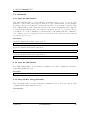
3.1 Introduction
The ASCII command set gives you the possibility to use the VSCAN device even with a
simple terminal program. This makes it very easy for you, to send some frames by hand
or to sniff the frames on the CAN bus in a simple human readable view. It will also be
possible to use such a simple semantic in a scripting system (e.g. Linux bash-script).
Every binary data will be sent and received by their ASCII hexadecimal equivalents.
The return values of all functions will be CR (ASCII 13) if the function succeeds or
BELL (ASCII 7) if the function fails. Some functions have extended return values,
but this will be described per function in the command description.
The received frames will be send directly to your ASCII communication channel - e.g.
serial port or network connection.
Version 1.7
VSCAN Manual
36
3
ASCII COMMAND SET
3.2 Commands
3.2.1 Open the CAN Channel
The CAN channel will be opened with the command O[CR], L[CR] or Y[CR]. The
difference between these three types is, that the second command will open the channel
in a listen only mode, in which no bus interaction will be done from the controller. The
last command will open the channel in a self reception mode, in which the device will also
receive the frames that it sents (only available in firmware version 1.4 or greater). Before
you will use one of the commands, you should setup a bus timing with the command S
or s. Anyway, the last configured bit rate is stored in the device and used as the standard
bus timing at power up.
Examples:
Open the channel in normal operation mode.
O[CR]
Open the channel in the listen only mode.
L[CR]
Open the channel in the self reception mode.
Y[CR]
3.2.2 Close the CAN Channel
The CAN channel will be closed with the command C[CR]. The command is only active
if the CAN channel is open.
Example:
C[CR]
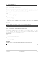
3.2.3 Setup the Bus Timing (Standard)
The bus timing will be setup-ed with the command Sn[CR]. You can only use this
command if the CAN channel is closed.
Parameters:
n
Version 1.7
VSCAN Manual
37
3
ASCII COMMAND SET
Could be one of the following values:
• 1 - 20 KBit
• 2 - 50 KBit
• 3 - 100 KBit
• 4 - 125 KBit
• 5 - 250 KBit
• 6 - 500 KBit
• 7 - 800 KBit
• 8 - 1 MBit
Example:
Configure a bus timing of 1 MBit.
S8[CR]
3.2.4 Setup the Bus Timing (Advanced)
A more user defined bus timing could be configured with the command sxxyy[CR].
As with the standard bus timing command above, you can only use it when the CAN
channel is closed.
Parameters:
xx
This is the hex value of the bit timing register 0.
For more information please take a look at the SJA1000 datasheet from NXP Semiconductors.
yy
This is the hex value of the bit timing register 1.
Example:
Configure a bus timing of 100 KBit.
s041C[CR]
Version 1.7
VSCAN Manual
38
3
ASCII COMMAND SET
3.2.5 Transmitting a Standard Frame
Transmitting a standard frame (11bit) over the CAN bus will be done with tiiildd[0-8].
The return value will be z[CR] or the normal error byte (BELL). As you can imagine,
this command is only available when the CAN channel is open.
Parameters:
iii
Standard frame (11bit) identifier.
l
Data length (0-8)
dd[0-8]
Data bytes in hex. The number of the bytes must be equal with the data length field.
Example:
Sending a frame with id 0x111 and three data bytes 0x10, 0x20, 0x30.
t1113102030[CR]
3.2.6 Transmitting a Standard Remote Request Frame
Transmitting a standard remote frame (11bit) over the CAN bus will be done with
riiil. The return value will be z[CR] or the normal error byte (BELL). This command
is only available when the CAN channel is open.
Parameters:
iii
Standard frame (11bit) identifier.
l
Data length (0-8)
Example:
Sending a remote request frame with id 0x111 and request 3 data bytes.
r1113[CR]
Version 1.7
VSCAN Manual
39
3
ASCII COMMAND SET
3.2.7 Transmitting an Extended Frame
Transmitting an extended frame (29bit) over the CAN bus will be done with Tiiiiiiiildd[0-8].
The return value will be Z[CR] or the normal error byte (BELL). The command is only
available when the CAN channel is open.
Parameters:
iiiiiiii
Extended frame (29bit) identifier.
l
Data length (0-8)
dd[0-8]
Data bytes in hex. The number of the bytes must be equal with the data length field.
Example:
Sending an extended frame with id 0x111 and three data bytes 0x10, 0x20, 0x30.
T000001113102030[CR]
3.2.8 Transmitting an Extended Remote Request Frame
Transmitting an extended remote request frame (29bit) over the CAN bus will be done
with Riiiiiiiil. The return value will be Z[CR] or the normal error byte (BELL).
The command is only available when the CAN channel is open.
Parameters:
iiiiiiii
Extended frame (29bit) identifier.
l
Data length (0-8)
Example:
Sending an extended remote request frame with id 0x111 and a request for 3 data bytes.
R000001113[CR]
Version 1.7
VSCAN Manual
40
3
ASCII COMMAND SET
3.2.9 Set Time-Stamps
The time-stamp command will set the time-stamp functionality on received frames on
or off. This command will only function, when the CAN channel is closed.
Example:
Will set time-stamps on or off.
Z1[CR]
Z0[CR]
3.2.10 Set Filter Mode
The command D1[CR] switch on the dual filter mode and with D0[CR] you switch over
to the single filter mode. For more information please take a look at chapter 2.2.3. This
command is only available if the CAN channel is closed. The firmware version must be
1.4 or greater.
Example:
Will set dual or single filter mode.
D1[CR]
D0[CR]
3.2.11 Set Acceptance Code and Mask Register
With the acceptance code command Mxxxxxxxx[CR] and mask register command
mxxxxxxxx[CR], you have the choice to filter for specific CAN messages directly on
the CAN controller side. For more information please take a look at chapter 2.2.3. This
command is only available if the CAN channel is closed.
Example:
We will filter for all standard frames between 0x300 and 0x3ff.
M00006000[CR]
m00001ff0[CR]
Version 1.7
VSCAN Manual
41
3
ASCII COMMAND SET
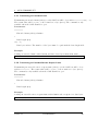
3.2.12 Get Status Flags
To get the status bits when an error occurred, you must use the command F[CR]. . For
more information on the bit-mask please take a look at chapter 2.2.3. The command is
only available if the CAN channel is open.
Example:
Retrieve the status bits as a hexadecimal value. The return value will be formatted like
this: Fxx[CR]
F[CR]
3.2.13 Get Version Information
To retrieve the current hard- and software version of the device, you must use the command V[CR]. The command is always available and will return the versions formatted
like this: Vxxyy[CR]. The hardware version is coded in the xx (major and minor version) and the software version in the yy (also coded as major and minor).
Example:
Retrieving the versions.
V[CR]
3.2.14 Get Serial Number
With the command N[CR] you will retrieve the serial number of the device. This command is always active and will return the decimal serial number like this: N12345678[CR].
Example:
Retrieving the serial number.
N[CR]
Version 1.7
VSCAN Manual
42
3
ASCII COMMAND SET
3.2.15 Get Extra-Information
You can retrieve extra information with the command I[CR]. The command is always
available and will return the values of the bus timing registers, the acceptance code and
mask register values, the counter of the arbitration lost interrupt, the arbitration lost
capture register, the status register and the value of the error code capture register of
the CAN chip. For more information please take a look at the SJA1000 datasheet from
NXP Semiconductors.
Example:
Retrieving the extra-information.
I[CR]
Version 1.7
VSCAN Manual
43
4
TOOLS
4 Tools
4.1 Firmware-Update
For every VSCAN device you can use our tool vs fw update.exe. It will determine the
type of device and will use the correct baudrate. If it did not, you can set the baudrate
explicitly.
SER-CAN: vs fw update.exe COMx vs can 1 6.bin 115200
Other devices: vs fw update.exe COMx vs can 1 6.bin 3000000
For the NET-CAN you should use the base64 web-frontend update file (e.g.
can 110 1 2 1.bin.b64), to update also the main network firmware in the device.
net-
4.2 Busmaster
You can download the Busmaster software for our devices from our website. For additional help and questions, please take a look at the Busmaster website.
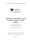
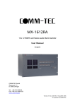
4.3 CANHacker
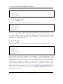
CANHacker is a tool for analyzing and transmitting frames on the CAN bus under MS
Windows OS. The Figure 11 will show you how the settings must be configured for the
VSCAN devices.
Version 1.7
VSCAN Manual
44
4
TOOLS
Figure 11: CANHacker Settings
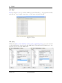
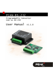
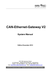
4.4 Wireshark
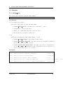
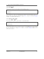
Wireshark5 is a well-known network packet sniffer. It is now possible to sniff via SocketCAN interface (Linux only) and parse CAN frames (Linux/Windows) . Figure 12 shows
frames captures via USB-CAN device (/dev/ttyUSB0 attached as slcan0).
5
www.wireshark.org
Version 1.7
VSCAN Manual
45
4
TOOLS
Figure 12: Wireshark
Version 1.7
VSCAN Manual
46
4
TOOLS
4.5 CANopen
4.5.1 Introduction
CANopen is a CAN-based higher layer protocol. It was developed as a standardized embedded network with highly flexible configuration capabilities. CANopen was designed
for motion-oriented machine control networks, such as handling systems. By now it is
used in various application fields, such as medical equipment, off-road vehicles, maritime
electronics, railway applications or building automation.
CANopen unburdens the developer from dealing with CAN-specific details such as bittiming and implementation-specific functions. It provides standardized communication
objects for real-time data, configuration data as well as network management data.6
One of the protocol implementations is the CanFestival Project (www.canfestival.org) .
It is an Open Source (LGPL and GPL) CANopen framework and is part of the Beremiz
Project (www.beremiz.org), an Open Source framework for automation. CanFestival
focuses on providing an ANSI-C platform independent CANopen stack that can be
implemented as master or slave nodes on PCs, Real-time IPCs, and Micro-controllers.
VScom devices will be already supported in the latest CanFestival version.
Wireshark can be used to capture and analyze CANopen traffic since version 1.7.1 (see
Section 4.4).
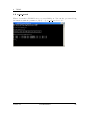
4.5.2 Running Example
You’ll find a small CanFestival example on the supplied CD showing the communication
between master and slave nodes. Following baudrates are supported: 20K, 50K, 100K,
125K, 250K, 500K and 1M. To execute this example decompress one of the following
archives:
• CANopen example win32.zip for Windows
• CANopen example linux.tar.bz2 for Linux
Under Windows connect two VScom CAN devices - for example two USB-CAN devices
installed as COM10 and COM11. Open two command windows and change to the directory
where the CANopen examples were extracted to and execute
TestMasterSlave -s COM10 -S 125K -M none -l libcanfestival_can_vscom.dll
in the first window and
TestMasterSlave -m COM11 -M 125K -S none -l libcanfestival_can_vscom.dll
in the second. Figure 13 shows the output messages of both nodes.
Under Linux connect two VScom CAN devices - for example two USB-CAN devices
installed as /dev/ttyUSB0 and /dev/ttyUSB1. Open two terminal windows and
change to the directory where CANopen examples were extracted to and execute
6
For more information see the website of CAN in Automation organization www.can-cia.org
Version 1.7
VSCAN Manual
47
4
TOOLS
export LD_LIBRARY_PATH=.
./TestMasterSlave -s „/dev/ttyUSB0” -S 125K -M none -l ./libcanfestival_can_vscom.so
in the first window and
export LD_LIBRARY_PATH=.
./TestMasterSlave -m „/dev/ttyUSB1” -M 125K -S none -l ./libcanfestival_can_vscom.so
in the second. Figure 14 shows the output messages of both nodes.
4.5.3 Compilation Instructions
CanFestival is stored in a Mercurial7 repository. To get CanFestival source code execute:
hg clone http://dev.automforge.net/CanFestival-3/
cd CanFestival-3
Configure and compile the library and examples:
./configure --can=vscom
make
The TestMasterSlave is located under examples/TestMasterSlave/ and the vscom
library is located under drivers/can_vscom/.
For detailed information about these examples and about using CanFestival in your
project refer to the doc/ folder.
7
Mercurial
Version 1.7
VSCAN Manual
48
4
TOOLS
(a) Master
(b) Slave
Figure 13: TestMasterSlave under Windows
(a) Master
(b) Slave
Figure 14: TestMasterSlave under Linux
Version 1.7
VSCAN Manual
49
4
TOOLS
4.6 Wrapper DLL System
In Linux operating system any application software may use CAN bus adapters from
different manufacturers, without modifying the program. An official CAN API named
SocketCAN exists for the Linux Kernel.
In Windows systems the situation is different. There is neither an API from Microsoft8 ,
nor a widely accepted de-facto standard used by manufacturers. All products come
with a proprietary driver to access the CAN bus adapter. On top is a set of libraries
for application programmers, encapsulating the hardware in higher layer function sets.
Application software tailored to use one set of libraries binds the application to certain
CAN bus hardware. Those libraries come in the form of DLLs.
VScom provides a system of wrapper DLLs. They provide the possibility to use any
VSCAN product as a replacement of products from other manufacturers, when those
are given a set of DLLs. The wrapper DLLs use the same name as the original set. They
provide the same functions used by the application software, so the existing software
shall not notice that exchange.
Installation: Copy the desired wrapper DLL over the original API DLL in your program
directory, thus replacing the version from the other manufacturer. It may be useful
to create a backup copy before doing so. You must also copy the latest VSCANAPI (vs can api.dll) into the same directory.
Configuration: If you want to specify a special configuration for the mapping of a VSCAN product, you can do this over a configuration file (vscan.ini). When there
is no configuration file available, the wrapper API uses the first VSCAN product
which will be found in the PC. You can also get extra debug informations when
you configure the debug option for the CAN channel in the configuration file. The
debug output will be saved in a file called vs can api.log in the program directory.
Configuration File Example:
[CAN_1.dll]
Port = "COM5"
debug = 0
[CAN_2.dll]
Port = "192.168.254.254:2001"
debug = 1
; VSCAN device over a (virtual) COM port
; mapping to VS-NET-CAN over IP and TCP port (raw mode)
; debug output is switched on (vs_can_api.log)
Note: In this example CAN 1.dll and CAN 2.dll are just sample text. Replace the text
in the brackets with the name of the DLL used by your application. So if in reality the
names are XCAN USB.dll and yCAN PCI.dll, use those names for the section titles.
The wrapper DLL finds the desired configuration by searching for a section, which is
titled by the DLLs name. The set of wrapper DLLs usually provides a sample configuration file.
Currently available are DLLs for the Light API from PEAK-System Technik GmbH.
8
See serial ports, manufacturers use the Windows API, products are interchangeable.
Version 1.7
VSCAN Manual
50
4
TOOLS
4.7 ZOC
ZOC (see Figure 15) is a powerful terminal program which has good logging functionality
and will also let you make connections over the network (telnet client).
Figure 15: ZOC
4.8 putty
With putty (http://www.chiark.greenend.org.uk/∼sgtatham/putty/) you can both talk
to the serial interface based devices like SER-CAN, USB-CAN and PCI-CAN and to the
network based devices like NET-CAN.
Version 1.7
VSCAN Manual
51
4
TOOLS
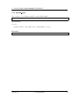
4.9 vs can search
This tool search for VSCAN devices on every COM port. You can also get extra debug
informations with the parameter -d[1-3]” - eg. vs can search.exe -d3”.
”
”
Version 1.7
VSCAN Manual
52
4
TOOLS
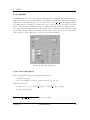
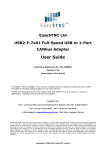
4.10 LabVIEW
LabVIEW (short for Laboratory Virtual Instrumentation Engineering Workbench) is a
platform and development environment for a visual programming language from National
Instruments. This section shows one possible way to use vs can api.dll with LabVIEW.
Specially prepared example (see Figure 16) can be found on the product CD9 . It lets the
user to send and read CAN frames after opening the channel with appropriate bitrate.
You can send CAN frames using the left panel. After configuring your CAN frame just
press Write On/Off” Button and frames will be sent each second. The incoming frames
”
will be shown on the right panel one per second if any available.
Figure 16: Example Application
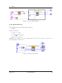
4.10.1 Open CAN Channel
The OpenChannel.vi has following input parameters:
• COM Port string
• speed as a number between 1 and 8 (as in Section 3.2.3).
Output parameters:
• return error code of VSCAN Open() or VSCAN Ioctl() routines
• CAN channel handle.
9
see VSCAN API x y z.zip\Wrapper\Languages\LabVIEW
Version 1.7
VSCAN Manual
53
4
TOOLS
Figure 17: Open CAN Channel
4.10.2 Read CAN Frame
The CanRead.vi has following input parameter:
• handle
Output parameters:
• return code value
• VSCAN MSG structure
• number of read bytes
CanRead.vi is designed to read one CAN frame per call. To read more bytes at once,
the buffer must be increased.
Figure 18: Read CAN Frame
Version 1.7
VSCAN Manual
54
4
TOOLS
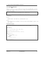
4.10.3 Write CAN Frame
The CanWrite.vi has following input parameters:
• handle
• parts of the VSCAN MSG structure
Output parameters:
• return code value
• number of written bytes
The VSCAN Write call is followed directly by VSCAN Flush call, so the CAN frame
will be sent immediately
Figure 19: Write CAN Frame
Version 1.7
VSCAN Manual
55
5
FREQUENTLY ASKED QUESTIONS
5 Frequently Asked Questions
All output from the CAN adapter will be written in one line in HyperTerminal?
You must configure the right settings and switch on ”Append line feeds to incoming
line ends”:
I’ve updated the driver of my USB-CAN, but the alias baudrate 9600 is not
functioning anymore?
There is a VBScript in the driver package, which must be called for each installed virtual
USB-CAN COM port:
cscript regmodify.vbs COM<x>
After executing the script USB-CAN must be disconnected for about 5 seconds and then connected again in order to use the baudrate aliases. Then you
can open the port with any standard baudrate - except 115kbps!
Version 1.7
VSCAN Manual
56