1
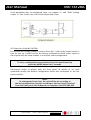
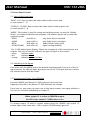
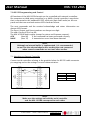
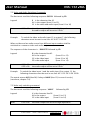
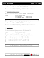
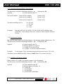
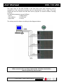
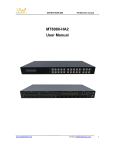
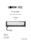
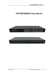
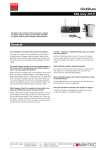
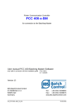
MX-1612RA
16 x 12 RGBHV and Stereo-Audio Matrix Switcher
User Manual
(English)
COMM-TEC GmbH
Siemensstr. 14
D-73066 Uhingen
Tel.: +49-7161-3000-0
Fax: +49-7161-3000-333
www.comm-tec.de
Version A1-Oct. 2004 Rev.1-Apr.2006 / DBA
© Copyright by COMM-TEC
User Manual
MX-1612RA
INDEX
1.0 Overview
2.0 Power Requirements and Installation
3.0 Settings
4.0 Attaching Inputs and Outputs
and Power Up
5.0 Front Panel Control
6.0 Infrared Remote Control
7.0 RS-232 Programming and Control
8.0 RS-485 Programming and Control
9.0 Technical Specifications
10.0 Warranty, Service and Returns Policy
Please read this manual carefully before installing the MX-1612RA.
COMM-TEC shall not be liable under any circumstances for consequential or
incidental damages and injuries including, but not limited to, labor costs or loss of
profits arising in connection with the use of or inability to use COMM-TEC
products.
COMM-TEC reserves the right to modify or discontinue designs, specifications,
warranties, and policies without notice.
COMM-TEC GMBH
SIEMENSSTRASSE 14
D-73066 UHINGEN
TELEFON +49(0)7161/3000-0
TELEFAX +49(0)7161/3000-333
WWW.COMM-TEC.DE
[email protected]
User Manual
MX-1612RA
1.0 OVERVIEW
Thank you for buying this product.
Please check the contents of the packaging carefully:
- (1) MX-1612RA unit
- (1) User Manual
- (1) Power Cord
The MX-1612RA unit is an 16 x 12 matrix for RGBHV and balanced Stereo Audio
signals. The possibility of programming output 12 as preview promotes more
versatile use of the matrix in certain multimedia applications. This preview output
can be used to view and listen to the sources without a routing or switching
operation.
The matrix can also manage Y,Cb,Cr signals. Presets can be stored and recalled.
The MX-1612RA provides the ‘through blank switching’ mode. That means that the
video portion of an input signal is delayed while the sync locks up. This prevents
the annoying effects during switching - the screen goes blank momentarily and
returns with a ‘locked’ video image.
The MX-1612RA can be controlled by the Front Panel, by a computer or a control
system via RS-232/RS-485 commands or with the optional Infrared Remote Control.
For RS-232/-485 protocols see chapter 7.0 and 8.0.
COMM-TEC GMBH
SIEMENSSTRASSE 14
D-73066 UHINGEN
TELEFON +49(0)7161/3000-0
TELEFAX +49(0)7161/3000-333
WWW.COMM-TEC.DE
[email protected]
User Manual
MX-1612RA
2.0 Power Requirements and Installation
The MX-1612RA must be connected to an electrical environment either of 230 Volt
or 115Volt 50 Hz to 60Hz. The power connector is at the left side on the rear panel.
Before applying power to the unit make sure that the power source has the correct
values and the voltage selector at the rear panel is set to the correct voltage. To
change the setting use a flathead screwdriver and and turn the selector that the
slot points to the required voltage indication.
Caution
Be aware of the risks of an electric shock.
Only qualified personnel should perform installations.
In some countries, the power plug must be adapted to local standards.
The wires are identified according to the following coding:
- Brown
- Blue
- Yellow/Green
PHASE
NEUTRAL
GROUND
(Identified with the letter L, maybe red)
(Identified with the letter N, maybe black)
(Identified with the letter E, maybe green)
Caution
For safety and signal integrity, use a grounded external power source and a
grounded power connector. Reliable earthing of rack mounted equipment
should be maintained.
If unit is installed in a 19 Inch rack consideration should be given to an
environment compatible with the manufacturer’s maximum rated ambient
temperature. Avoid placing high heat-producing equipment directly above or
below the MX-1612RA.
The power connector contains the power switch and the fuse drawer for 5x20
fuses. If the fuse blows, replace it only with the same type and value
(T 500mA/250V).
3.0 SETTINGS
The MX-1612RA unit does not have internal settings. Some settings or presets can
be made directly from the keypad.
COMM-TEC GMBH
SIEMENSSTRASSE 14
D-73066 UHINGEN
TELEFON +49(0)7161/3000-0
TELEFAX +49(0)7161/3000-333
WWW.COMM-TEC.DE
[email protected]
User Manual
MX-1612RA
4.0 Attaching Inputs and Outputs and Power Up
4.1 Video Signals
Note:
For the video connections, use good quality 75Ω coax cable.
Switch the MX-1612RA off while attaching the signal cables.
Connect the sources and destinations according to the screen-printed instructions
on the rear panel.
Note:
The RGB inputs are terminated at 75Ω.
Looping of the inputs is not possible. If necessary, duplicate the incoming
signal with an COMM-TEC DA-12R unit.
Note:
Some monitors or video projectors equipped with a
15pin HD connector require bridge of pin # 5 to GND.
4.2 Audio Signals
Connect the audio sources and destinations according to the screen-printing on the
rear panel. Don’t mix up the right and left channel of your Stereo Audio signals.
The audio inputs and outputs are for balanced signals. If the source has an
unbalanced output, put the hot signal on input “a” of the MX-1612RA, connect the
ground of the signal and input “b” to “GND”.
COMM-TEC GMBH
SIEMENSSTRASSE 14
D-73066 UHINGEN
TELEFON +49(0)7161/3000-0
TELEFAX +49(0)7161/3000-333
WWW.COMM-TEC.DE
[email protected]
User Manual
MX-1612RA
If the destination has an unbalanced input, use outputs “a” and “GND” leaving
output “b” free. In this case, half of the output level is lost.
4.3 Power Up of the MX-1612RA
Be sure that the voltage setting is correct! Press the ‘I’ side of the power switch to
turn the unit on. It will be set to the factory configuration which routes inputs to
the outputs with the same number or to the last saved configuration.
Note:
To save a configuration and activate this at the next Power-Up,
press the MODE button for 2 seconds.
Subsequent recalls of presets from the front panel, IR remote or via serial
commands modify the default configuration which will correspond to the last
preset recalled.
Note:
At subsequent Power-Ups, the unit will be set according to
the last configuration saved or according to the last "recall" received
from the front panel, the IR-Remote or computer via RS-232/RS-485.
COMM-TEC GMBH
SIEMENSSTRASSE 14
D-73066 UHINGEN
TELEFON +49(0)7161/3000-0
TELEFAX +49(0)7161/3000-333
WWW.COMM-TEC.DE
[email protected]
User Manual
MX-1612RA
5.0 Front Panel Control
5.1 Parts of the Front Panel
‘INPUT 1-16’: Keys to select the video and/or audio sources and
to save presets 1 – 8 .
‘OUTPUT 1-12 (PW)’: Keys to select the video and/or audio outputs and
to recall presets 1 – 8.
‘MODE’: This button is used for saving and recalling presets, to save the ‘Default
Status’, to enable and disable the reception of IR remote signals and to select the
operation mode:
- VIDEO
red LED on
only Video level is switched
- AUDIO
green LED on
only Audio level is switched
- BOTH
both LEDs on
Audio-follows-Video (AfV)
- LOCK/VOLUME
both LEDs off
signal routing disabled
16 x 12 LED Matrix Status Display: Shows the crosspoints of the routed inputs and
outputs. The color of the LED indicates the type of signal on the output:
- green
indicates audio
- red
indicates video
- orange
indicates audio and video
5.2 Switching of the Signals
First select with the MODE button the desired switching mode. Press one of the 16
Input buttons, the LED will light. Next press one of the 12 Output buttons to which
the selected source shall be routed.
5.3 Programming Output 12 as PREVIEW
Press the "MODE" and Output 12 (PW) button at the same time.
Lighting of the LED in the button 12 (PW) indicates the change.
From now on, each time you press one of the input buttons, the signal relative to
this input is switched immediately to output 12.
Note:
When output 12 is active as PREVIEW output,
the LED in the output 12 (PW) button is on.
To change output 12 back to normal output press the "MODE" and output 12
button again at the same time - LED in output 12 (PW) button goes off.
COMM-TEC GMBH
SIEMENSSTRASSE 14
D-73066 UHINGEN
TELEFON +49(0)7161/3000-0
TELEFAX +49(0)7161/3000-333
WWW.COMM-TEC.DE
[email protected]
User Manual
MX-1612RA
5.4 Programming the default configuration
Press the MODE button for 2 seconds – this saves the present configuration and
activate this at the next power-on. Subsequent "recall" from keypad or computer
modifies the default configuration that will correspond to the last status recalled.
5.5 Presets – Saving and Recall
Eight Presets can be saved and then recalled pressing a combination of keys.
Button
Mode+Input1
Mode+Input2
Mode+Input3
Mode+Input4
Mode+Input5
Mode+Input6
Mode+Input7
Mode+Input8
Function
Save status 1
Save status 2
Save status 3
Save status 4
Save status 5
Save status 6
Save status 7
Save status 8
Button
Mode+Output1
Mode+Output2
Mode+Output3
Mode+Output4
Mode+Output5
Mode+Output6
Mode+Output7
Mode+Output8
Function
Recall status 1
Recall status 2
Recall status 3
Recall status 4
Recall status 5
Recall status 6
Recall status 7
Recall status 8
Note:
A recalled Preset switching operation is not performed
in the ‘through blank’ mode (Sync-RGB delay).
5.6 Setting the switching time delay
The MX-1612RA performs ‘through blank switching’ - the video portion of an input
signal is delayed while the sync locks up. The screen goes blank momentarily and
returns with a ‘locked’ video image. This prevents the annoying effects typical of
LCD devices when their input signal is switched.
As each LCD has its own response time, for optimal switching, the user can modify
blank duration from 0.3 to 2 seconds. When the ‘MODE’ button is in LOCK
position, the current switching time is displayed by the LEDs in the ‘INPUT’ buttons
13, 14, 15 and 16 as shown
in the following table:
LED in
INPUT button
IN 13
IN 14
IN 15
IN 16
COMM-TEC GMBH
Switching
delay time
300 msec
500 msec
1 sec
2 sec
SIEMENSSTRASSE 14
D-73066 UHINGEN
TELEFON +49(0)7161/3000-0
TELEFAX +49(0)7161/3000-333
WWW.COMM-TEC.DE
[email protected]
User Manual
MX-1612RA
To set a new switching time press the correspondent button for 2 seconds. Default
value is 500 msec.
When the delay time is set by the front panel it is valid for all outputs, including the
preview output. By serial control it is possible to set the switching time for each
output independently; in this case the LEDs in the INPUT buttons 13, 14, 15 and 16
show the switching time for the output 1.
The update of 16 x 12 LED Matrix Status Display is dependent on the switching of
the RGB signals, therefore the effective change of the status is delayed related to
the switching time.
5.7 Enabling/Disabling the IR reception
Press and hold the ‘MODE’ button at power up:
Enables or disables the reception from IR remote control,
depending on the current status.
6.0 Infrared Remote Control
The MX-1612RA can be controlled via an IR remote control which must be ordered
separately. (Cat.-No. 708IRMX1612RA)
Note:
The remote control is self-learning. If the battery supply has been interrupted,
press the ‘SET’ key for a few seconds.
Be sure that the infrared reception is enabled (see chapter 5.7).
The unit is shipped with IR reception enabled.
The following functions can be performed with the IR remote control:
V, A, A+V, LOCK
Selection of the operation mode (Audio only, Video only,
AfV, Lock - like ‘MODE’ on the front panel
IN 1 - 16
Selection of a source/input (like from the front panel)
OUT 1 - 12
Selection of a destination/output (like from front panel)
PREVIEW Video Mute ON
PREVIEW Video Mute OFF
De-activates the video on the preview output (12)
Re-activates the video on the preview output (12)
PREVIEW Audio Mute ON
PREVIEW Audio Mute OFF
De-activates the audio on the preview output (12)
Re-activates the audio on the preview output (12)
SAVE
RECALL
followed by OUT keys 1÷8 save a status
followed by OUT keys 1÷8 recall a status
COMM-TEC GMBH
SIEMENSSTRASSE 14
D-73066 UHINGEN
TELEFON +49(0)7161/3000-0
TELEFAX +49(0)7161/3000-333
WWW.COMM-TEC.DE
[email protected]
User Manual
MX-1612RA
7.0 RS-232 Programming and Control
All functions of the MX-1612RA matrix can be controlled with external controllers
like computers or third party controllers (e.g. AMX). A serial controller is any device
that is connected to the standard RS-232 serial port (9pin SubD male) on the rear
panel and that can send and receive ASCII character format.
The sent commands and the received acknowledge and status information are
always ASCII format.
The Input, Output and Preset numbers are always two-digit.
The end of string (CR) is hex 0D.
The MX-1612RA matrix replies (except for status and firmware request):
ACK
(Hex 06)
if the command has been performed correctly
NACK
(Hex 15)
if transmission errors have been detected
Note:
Although an internal buffer is implemented, it is recommended
to wait for the acknowledge before sending the next command
when several commands are sent one after another
7.1 Attaching an External Controller
Connect serial controllers refering to the graphics below for RS-232 cable connector
pin mapping and to the settings for serial communication:
BAUD
Data Bits
Stop Bit
Parity
Note:
Make sure the settings on both the serial controller
and the MX-1612RA correspond to each other
COMM-TEC GMBH
SIEMENSSTRASSE 14
D-73066 UHINGEN
TELEFON +49(0)7161/3000-0
TELEFAX +49(0)7161/3000-333
WWW.COMM-TEC.DE
[email protected]
9600
8
1
NONE
User Manual
MX-1612RA
7.2 Video and Audio Switching Commands
The host must send the following sequence: BXXYY followed by CR
Legend:
B is the character Hex 42
XX is the output (from 01 to 12)
YY is the video and audio input (from 01 to 16)
Note:
if YY is 00
the video output will be set to high impedance
the audio output will be set to 0 Volt
Example:
To switch the video and audio input 15 to output 7, the following
characters must be sent in one line: 42 30 37 31 35 0D
When a video and an audio source from different input numbers shall be
switched to a common video and audio output:
The sequence of the characters is: BXXYYZZ followed by CR
Legend:
Note:
Example:
B is the character Hex 42
XX is the output
YY is the video input
ZZ is the audio input
if YY is 00
if ZZ is 00
(from 01 to 12)
(from 01 to 16)
(from 01 to 16)
the video output will be set to high impedance
the audio output will be set to 0 Volt
To switch the video input 1 and the audio input 3 to output 12, the
following characters must be sent in one line: 42 31 32 30 31 30 33 0D
The matrix returns ACK (Hex 06) if okay or NACK (Hex 15) in case of error(s),
(see above, chapter 7.0).
7.3 Video only switching command
The host must send the following sequence: VXXYY
Legend:
followed by CR
V is the character Hex 56
XX is the output
(from 01 to 12)
YY is the video input
(from 01 to 16)
Note:
if YY is 00
COMM-TEC GMBH
SIEMENSSTRASSE 14
D-73066 UHINGEN
the video output will be set to high impedance
TELEFON +49(0)7161/3000-0
TELEFAX +49(0)7161/3000-333
WWW.COMM-TEC.DE
[email protected]
User Manual
Example:
MX-1612RA
To bring video output 8 to high impedance, the following characters
must be sent in one line: 56 30 38 30 30 0D
The matrix returns ACK (Hex 06) if okay or NACK (Hex 15) in case of error(s).
7.4 Audio only switching command.
The host must send the following sequence: AXXYY
Legend:
followed by CR
A is the character Hex 41
XX is the output
(from 01 to 12)
YY is the audio input
(from 01 to 16)
Note:
if YY is 00
the audio output will be set to 0 Volt
Example:
To bring audio output 8 to 0 Volt, the following characters
must be sent: 41 30 38 30 30 0D
The matrix returns ACK (Hex 06) if okay or NACK (Hex 15) in case of error(s).
7.5 Status Request
The host must send the following sequence: D followed by CR
Legend:
D is the character Hex 44
The matrix returns 24 pairs of ASCII characters followed by CR.
12 pairs for the Video and 12 for the audio input/output combinations:
YY
the video input present on output 1 (from 01 to 16)
ZZ
the audio input present on output 1 (from 01 to 16)
/ ---------------------------------- / / ---------------------------------- /
YY
the video input present on output 12 (from 01 to 16)
ZZ
the audio input present on output 12 (from 01 to 16)
CR
Note:
If the matrix returns 00 (or 30 30), the video portion is set
to high impedance or the audio portion is at 0 Volts.
COMM-TEC GMBH
SIEMENSSTRASSE 14
D-73066 UHINGEN
TELEFON +49(0)7161/3000-0
TELEFAX +49(0)7161/3000-333
WWW.COMM-TEC.DE
[email protected]
User Manual
MX-1612RA
7.6 Creating a Preset
The MX-1612RA can perform up to 8 presets, saved in the internal memory. A
preset is a predefined configuration of 24 crosspoints, 12 video and 12 audio,
which can be recalled at any time.
The presets are created from the current status of the matrix and are restored after
a loss of power.
The host must send the following sequence: SNN
Legend:
Example:
S the character Hex 53
NN is the preset number
followed by CR
(from 01 to 08)
If preset 05 is to be assigned to the current state of the matrix, the
host will send the following sequence in one line: 53 30 35 0D
The matrix returns ACK (Hex 06) if okay or NACK (Hex 15) in case of error(s).
7.7 Recall of a Preset
A predefined preset can be recalled.
The host must send the following sequence: RNN
Legend:
Example:
R is the character Hex 52
NN is the preset number
followed by CR
(from 01 to 08)
If the preset saved under number 05 shall be recalled, the host must
send the following sequence: 52 30 35 0D
The matrix returns ACK (Hex 06) if okay or NACK (Hex 15) in case of error(s).
7.8 Firmware Release Request
The host must send the following sequence: i
Legend:
followed by CR
i is the character Hex 69
The matrix replies:
i
(Hex 69)
P
high byte indicating the firmware
(Hex 50)
Z
low byte that identifies the firmware release (from Hex 30 to Hex 39)
CR
Example:
Reply 69 50 30 OD indicates that the firmware release is 0.
The character P (Hex 50) identifies the firmware of the matrix.
COMM-TEC GMBH
SIEMENSSTRASSE 14
D-73066 UHINGEN
TELEFON +49(0)7161/3000-0
TELEFAX +49(0)7161/3000-333
WWW.COMM-TEC.DE
[email protected]
User Manual
MX-1612RA
7.9 Global Status Request
The host must send the following sequence: d followed by CR
Legend:
d is the character Hex 64
The matrix returns 24 pairs of ASCII characters followed by CR.
12 pairs for the Video and 12 for the audio input/output combinations:
YY
the video input present on output 1 (from 01 to 16)
ZZ
the audio input present on output 1 (from 01 to 16)
/ ---------------------------------- / / ---------------------------------- /
YY
the video input present on output 12 (from 01 to 16)
ZZ
the audio input present on output 12 (from 01 to 16)
CR
Note:
If the matrix returns 00 (or 30 30), the video portion is set
to high impedance or the audio portion is at 0 Volts.
P
number of the preset activated (from 1 to 8)
T
enabling of remote control (0=disabled, 1=enabled)
V
12th output used as preview (0=output 12 used normally, 1= preview
output)
A
machine address on RS485 (from 0 to 7)
S
Tx/Rx speed on RS485 (1=2400 bit/sec, 2=9600 bit/sec)
R
reply time (from 1 to 7, a multiple of 16 ms, or from 16 ms to 112 ms)
CR
7.10 Set ‘Switching Through Blank’ time
The host must send the following sequence: WXXY
Legend:
Y indicates the time:
followed by CR
W is the character Hex 57
XX is the output
(from 01 to 12)
(from 0 to 3)
0 = 0,3 sec.
1 = 0,5 sec.
2 = 1 sec.
3 = 2 sec.
The matrix returns ACK (Hex 06) if okay or NACK (Hex 15) in case of error(s).
Example:
to set the switching delay time of output 5 to 1 second, the following
characters must be sent in line: 57 30 35 32 0D
COMM-TEC GMBH
SIEMENSSTRASSE 14
D-73066 UHINGEN
TELEFON +49(0)7161/3000-0
TELEFAX +49(0)7161/3000-333
WWW.COMM-TEC.DE
[email protected]
User Manual
MX-1612RA
7.11 ‘Switching Through Blank’ time request
The host must send the following sequence: w
followed by CR
Legend:
w is the character Hex 77
The matrix replies: Y time set for output 1
Y time set for output 2
“
“
“
Y time set for output 12
The time according to Y is:
Example:
(from 0 to 3)
(from 0 to 3)
“
“
(from 0 to 3)
0 = 0,3 sec.
1 = 0,5 sec.
2 = 1 sec.
3 = 2 sec.
the reply 30 30 30 30 30 30 31 30 30 30 30 30 0D indicates that
output No. 7 has a delay of 0,5 sec., while all other outputs switch in
0,3 sec..
7.12 Set Preview Output
MX-1612RA shall connect a selected input to the preview output (fixed to No. 12).
The host must send the following sequence: pX
followed by CR
Legend:
p is the character Hex 70
X changes status of output 8
1= output 12 is preview out
0 = output 12 is set as standard output
Example:
To set output 12 to a preview output the host must sent: 70 31 0D
The matrix returns ACK (Hex 06) if okay or NACK (Hex 15) in case of error(s).
7.13 Set Mute on Preview Output
When output 12 is used as a Preview output, it can be muted.
The host must send the following sequence: mX followed by CR
Legend:
COMM-TEC GMBH
m is the character Hex 6D
X changes status of output 12
0 = mute OFF
1 = mute Audio
2 = mute Video
3 = mute Audio and Video
SIEMENSSTRASSE 14
D-73066 UHINGEN
TELEFON +49(0)7161/3000-0
TELEFAX +49(0)7161/3000-333
WWW.COMM-TEC.DE
[email protected]
User Manual
Example:
MX-1612RA
to mute the audio on preview send the following sequence: 6D 31 0D
The matrix returns ACK (Hex 06) if okay or NACK (Hex 15) if output 12 has not
been previously defined as preview out or in case of transmission error(s).
7.14 Set RS-485 Communication Parameters
The host must send the following sequence: CASR
Legend:
followed by CR
C is the character Hex 43
A is the address of the matrix (from 0 to 7)
S is the Tx/Rx speed (1 or 2)
1 = 2400 bit/sec
2 = 9600 bit/sec
R is the reply time (from 1 to 7) in multiples of 16 msec.
1 = 16 msec
2 = 32 msec
3 = 48 msec
4 = 64 msec
5 = 80 msec
6 = 96 msec
7 = 112 msec
The matrix returns ACK (Hex 06) if okay or NACK (Hex 15) in case of error(s).
Example:
to program the connected matrix as unit with address 4, Tx speed of
2400 bit/sec and a reply time of 80 milliseconds, the following
characters must be sent on line: 43 34 31 35 0D
8.0 RS-485 Programming and Control
All functions of the MX-1612RA can be controlled by a computer through
transmission/reception of strings of hexadecimal and ASCII characters. The
transmission protocol is of the master/slave multi-point type where the MX-1612RA
are the slaves while the host that controls these is the master. Up to 8 MX-1612RA
identified by addresses form 0 to 7 can be connected on the 485 bus.
The characteristics of the serial connection are:
8 data bits, no parity, 1 stop bit and speed settable to 2400 or 9600 baud
The transmission speed, the address of the unit and the reply time can be set with
a suitable command from RS-232 (see chapter 7.14).
COMM-TEC GMBH
SIEMENSSTRASSE 14
D-73066 UHINGEN
TELEFON +49(0)7161/3000-0
TELEFAX +49(0)7161/3000-333
WWW.COMM-TEC.DE
[email protected]
User Manual
MX-1612RA
The reply time of the MX-1612RA is the time that must pass between end of
reception of the command and the start of transmission of the reply. This time
allows the host to release the 485 bus and to prepare to receive without causing
conflicts.
The default parameters are as follows:
- speed
= 9600 bit/sec
- unit address
= 0 (30 hex)
- reply time
= 32 ms
The wiring must be done according to the diagram below:
Note:
When several units are daisy-chained the 100 Ohm termination
must be placed by the last unit
COMM-TEC GMBH
SIEMENSSTRASSE 14
D-73066 UHINGEN
TELEFON +49(0)7161/3000-0
TELEFAX +49(0)7161/3000-333
WWW.COMM-TEC.DE
[email protected]
User Manual
MX-1612RA
According to the used protocol, the messages between the host and MX-1612RA
correspond to the following sequences:
- command from host to MX-1612RA:
STX ADDR command ETX
- reply of the MX-1612RA to the host:
STX ADDR reply ETX
The character STX corresponds to 02 hex,
the character ETX corresponds to 03 hex,
the ADDR field is the address of the MX-1612RA: from 30 hex to 37 hex (or from 0
to 7 in ASCII)
The contents of the command and reply fields are the same as in the RS-232 protocol
except for the CR character (hex 0D) which is omitted in this case.
8.1 Commands and replies
The commands that can be sent via RS-485 are the same as for RS-232 except for
the "Set RS-485 communication parameters" (see 7.14) command:
- video and audio switching command
7.2
- video switching command
7.3
- audio switching command
7.4
- status request
7.5
- creation of a preset
7.6
- recall of a preset
7.7
- firmware release identification request
7.8
- global status request
7.9
- set ‘Switching Through Blank’ time
7.10
- ‘Switching Through Blank’ time request
7.11
- set preview output
7.12
- set mute on preview output
7.13
Example: A video switching command will be as follows:
STX ADDR VXXYY ETX
where:
V is the character Hex 56
XX is the output
(from 01 to 12)
YY is the video input
(from 01 to 16)
The MX-1612RA matrix replies:
STX ADDR ACK ETX
where: ACK is the character Hex 06
if the command has been performed correctly
STX ADDR NACK ETX
where NACK is the character Hex 15
if transmission errors have been detected or incorrect parameters.
Therefore, the switching command of video input 5 to output 4 for the MX-1612RA
with address 2 will be as follows:
STX 2 V 04 05 ETX
(in Hex code: 02 32 56 30 34 30 35 03)
the matrix will reply with:
STX 2 ACK ETX
(in Hex code: 02 32 06 03) or with:
STX 2 NACK ETX
(in Hex code: 02 32 15 03)
COMM-TEC GMBH
SIEMENSSTRASSE 14
D-73066 UHINGEN
TELEFON +49(0)7161/3000-0
TELEFAX +49(0)7161/3000-333
WWW.COMM-TEC.DE
[email protected]
User Manual
MX-1612RA
9.0 Technical Specifications
Name
Type
Cat.-No.
Matrix Switcher
MX-1612RA
708MX1612RA
Video
Inputs
Input connectors
Input coupling
Input impedance
Crosstalk (worst case)
Bandwidth
Outputs
Output connectors
Sync
Switching Time between
RGB and Sync signals
Audio
Input type
16, RGBHV or YUV or RGBS
16 x 5 BNC female
DC
75 Ω
43 dB at 40 MHz
350 MHz
12, RGBHV or YUV or RGBS
12 x 5 BNC female
H+V separated, TTL level, High Z
Adjustable at 0.3, 0.5, 1 and 2 seconds
Input level
Output impedance
Frequency response
Distortion
Crosstalk (worst case)
Hum & noise
Differential, AC,
balanced with Phoenix screw terminal, removable
44 kΩ differential
22 kΩ single ended
+9 dBm max.
600 Ω
-0,1 dB from 20 Hz to 600 kHz
<0,2% from 20 Hz to 20 kHz at +6 dBm
55 dB at 16 kHz
-63 dBm unweighted (worst case)
Main input
Power consumption
230 / 115VAC VAC, 50 / 60 Hz
15 VA
Housing
Size (W x D x H)
Weight
Metal, grey
483 x 220 x 264 mm, 19" rack mountable, 6ru high
8,6 Kg
Operating temp. range
Safety
EMC
0 - 45°C
according to EN 60065
according to EN 55103-1 and EN 55103-2
Optional Accessories
IR-MX-1612RA: IR remote control
Cat.-No. 708IRMX1612RA
Input Impedance
Specifications are subject to change without notice
COMM-TEC GMBH
SIEMENSSTRASSE 14
D-73066 UHINGEN
TELEFON +49(0)7161/3000-0
TELEFAX +49(0)7161/3000-333
WWW.COMM-TEC.DE
[email protected]
User Manual
MX-1612RA
10.0 Warranty, Service and Returns Policy
This product is under warranty for a period of two (2) years from the date of
purchase.
COMM-TEC’s liability and Buyer’s remedies under this warranty shall be limited
solely to repair of the faulty units free of charge.
This warranty does not apply if the product has been modified, repaired by an
unauthorized agent, or improperly installed, used, or maintained.
If a problem occurs first contact your dealer or COMM-TEC for trouble shooting.
If verification of a problem requires factory repair, ask COMM-TEC’s Customer
Equipment Service representative to issue a
Return Materials Authorization (RMA) number.
Merchandise will not be accepted without a RMA number.
When returning a product to COMM-TEC in Uhingen for repair please comply with
the following instructions:
• Shipping and insurance costs must be prepaid
• Use original shipping container(s), (if possible)
• Indicate the RMA number clearly on the outside of each container
• Enclose a written description of the problem
The under warranty repaired units will be returned Carriage Free to the sending
party (dealer or consumer).
Outside the warranty period, COMM-TEC will repair the faulty units, charging all
arising expenses of the repair e.g. labor, parts, transportation and insurance, to the
sending party (dealer or consumer).
For any problems during installation and operation of the MX-1612RA
call the COMM-TEC hotline +49 07161 3000-0,
send a fax +49 07161 3000-333
or e-mail to [email protected]
COMM-TEC GMBH
SIEMENSSTRASSE 14
D-73066 UHINGEN
TELEFON +49(0)7161/3000-0
TELEFAX +49(0)7161/3000-333
WWW.COMM-TEC.DE
[email protected]