Transcript
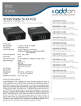
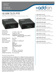
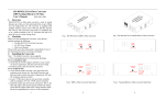
Dual color:10M Link/Act * MC-2GT-SFP TP2 GREEN: 1000M Link/Act RED:100M Link/Act Dual color:10M Link/Act * 2-Port 10/100/1000Base-TX to 1000Base-FX SFP Converter FX ON: optic fiber cable is connected well PWR ON: the power is ok *Dual color: Two LED chips (in one package) are all bright or blinking at the same time. Introduction to DIP switches NO Function Status Description 1 Reserved X X 2 Jumbo frame OFF Port isolation OFF * ON Normal Up to 9KB Disable Enable FX 100M OFF FX 1000M ON FX 100M ON 3 4 *between two RJ-45 ports Main features 1. In conformity to IEEE802.3 IEEE802.3Z 1000Base-Tx/Fx standards. 2. Supports IEEE802.3X flow control. User Manual 3. Supports 100Base-FX interface. 4. Supports auto MDI-MDIX function. 5. Supports jumbo frame up to 9.6KB. Brief introduction 6. Supports port based isolation. MC-2GT-SFP is a dual copper and one fiber Gigabit Ethernet converter and switch, and is designed to make conversion between 10/100/1000Base-T and 100/1000Base-X with SFP connector. This converter supports IEEE802.3 IEEE802.3Z 1000Base-TX/FX protocols. Technical parameters: 1. Standard Protocol: IEEE 802.3,IEEE802.3Z 1000 Base-TX/FX, IEEE802.3X, 2. Connector: 2 RJ-45 Jacks, one SFP Slot one DC-inlet connector Packing List 3. Operation mode: full duplex or half duplex mode Please check the following items in the package before installing the media converter. 4. Power supply parameter: Mini media converter 1 Unit 5. Environmental temperature: 0℃-50 ℃ AC/DC Power adaptor 1 PCS 6. Relative humidity: 5%-90% User Manual 1 Copy 8. TP cable: Cat5e or CAT6 UTP cable Please contact us immediately for any loss or damage to the above items. 9. Optical fiber: Installation Multi-mode: 1. Interface Single mode: RJ-45 interface The transmission media adopts CAT5e or CAT6 twisted-pair with maximum length up to 5-12VDC 50/125, 62.5/125 or 100/140μm 8.3/125, 8.7/125, 9/125 or 10/125μm 10 Dimensions: 100 meters (330feets). 90mm (L) x 60mm (W) x 20mm (H) Fiber interface (Not including SFP transceiver module length) SFP fiber interface is of duplex mode type, including two interfaces, namely TX and RX. When the two sets of optical transceiver are interfaced or connected to switch with fiber interface, the fiber is in cross connection, namely "TX-RX", "RX-TX" (direct butting for single optical fiber Cautions: transceiver module). 1. This product is suitable for indoor applications. Power supply interface 2. Put on the dust cover of fiber interface when not used. The AC/DC power adaptor is connected to DC-input jack of media converter. 3. It is forbidden to stare at the TX fiber-transfer end with naked eyes. 4. WDM transceivers must be used in pair. 2. Connection The network device (IP camera, wireless AP, VoIP phone, etc) with RJ-45 interface is connected to RJ-45 jack of media converter through twisted-pair. And the multi/single mode optical fiber is Trouble shooting: connected to SFP fiber interface of the optical transceiver module. Then connect the AC power 1. Device is not matched. Please select the corresponding network device according to the adaptor, the media converter will work. The corresponding LED is on for correct connection transfer rate of the product (10Mbps or 100Mbps or 1000Mbps) when connected to other (See the table below for the LED indicator lamp) . network devices. 2. Line loss is excessive during the fiber wiring. Excessive loss in connector plug-in and fiber soldering and excessive intermediate nodes may cause excessive loss rate or abnormal operation. Description for LED indicator lamp LED indicator lamps serve as device monitoring and trouble display. The following is the description for each LED indicator lamp. TP1 GREEN: 1000M Link/Act RED:100M Link/Act