1
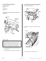
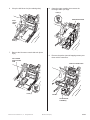
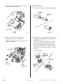
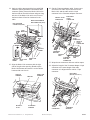
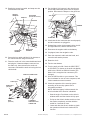
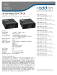
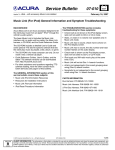
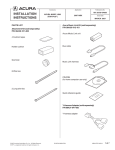
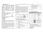
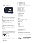
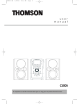
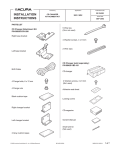
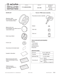
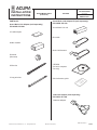
Accessory
INSTALLATION
INSTRUCTIONS
Application
Publications No.
BII 32604-34945
ACURA MUSIC LINK™
(FOR iPod® )
PARTS LIST
Acura Music Link Adapter (sold separately)
P/N 08A28-1H1-800
2007 RDX
Issue Date
MARCH 2007
Acura Music Link Adapter Kit (sold separately)
P/N 08A28-1H2-100
Acura Music Link unit
4 Cushion tapes
Bus cable
Holder cushion
Music Link harness
Grommet
(Not used)
8 Wire ties
2 Long wire ties
CD-ROM
(for home computer
use only)
Quick reference guide
Y-Harness Adapter (sold separately)
P/N 08A31-0F1-000
Y-harness adapter
© 2007 American Honda Motor Co., Inc. - All Rights Reserved.
BII 32604-34945 (0703)
08B28-STK-2000-91
1 of 6
3.
TOOL AND SUPPLIES REQUIRED
#2 Phillips screwdriver
Diagonal cutters
Ratchet
10 mm Socket
Shop towel
Open and lower the glove box, disconnect the
damper, then push in on the side of glove box to
open it past the stoppers.
DAMPER
Illustration of the Acura Music Link Installed on
the Vehicle
Push.
MUSIC LINK
UNIT
Push.
MUSIC LINK
HARNESS
GLOVE
BOX
6204021B
4.
Remove the right center console side trim (four
clips).
CLIPS (4)
BUS
CABLE
6206032B
INSTALLATION
Client Information: The information in this
installation instruction is intended for use only by
skilled technicians who have the proper tools,
equipment, and training to correctly and safely add
equipment to your vehicle. These procedures
should not be attempted by “do-it-yourselfers.”
1.
2.
RIGHT CENTER
CONSOLE SIDE TRIM
Make sure you have the anti-theft code for the
radio, then write down the frequencies for the
preset buttons.
6204030B
Disconnect the negative cable from the battery.
5.
2 of 6
BII 32604-34945 (0703)
Move the shift lever to the N position.
© 2007 American Honda Motor Co., Inc. - All Rights Reserved.
6.
Lift up the shift lever trim (six retaining tabs).
8.
Open the center console, then remove the
beverage holder (six clips).
CLIPS (6)
BEVERAGE HOLDER
SHIFT
LEVER
TRIM
RETAINING
TABS (6)
6204050B
7.
Remove the left center console side trim (three
clips).
6204071B
9.
Remove the pocket (two self-tapping screws) and
three vehicle connectors.
LEFT CENTER
CONSOLE SIDE
TRIM
VEHICLE CONNECTORS
CLIPS (3)
6204061B
POCKET
SELF-TAPPING
SCREWS (2)
© 2007 American Honda Motor Co., Inc. - All Rights Reserved.
BII 32604-34945 (0703)
6204081B
3 of 6
10. To prevent scratching the shift lever and trim,
cover them with a shop towel.
Routing The Harness
12. Insert the Music Link unit into the holder cushion.
HOLDER
CUSHION
MUSICLINK
UNIT
SHIFT LEVER
SHOP
TOWEL
Align ends.
6417010B
5426010B
11. Remove the audio unit (four bolts) and
disconnect the five vehicle connectors.
NOTE: The antenna connector release is on the
side of the connector.
13. Connect the bus cable DIN connector (black) and
the Music Link harness DIN connector (white) to
the Music Link unit.
NOTE: To avoid connector damage, orient the
connectors properly with the flat side up, and
insert them straight in (not crooked.) To remove,
pull back on the slide collar to release a locking
mechanism. Do not pull on the cable, or you can
damage it.
AUDIO UNIT
MUSIC LINK UNIT
MUSIC LINK
HARNESS DIN
CONNECTOR
(white)
MUSIC LINK
UNIT
VEHICLE
BOLTS (4)
VEHICLE
CONNECTORS
BUS CABLE
DIN
CONNECTOR
(black)
6204090B
6523010B
4 of 6
BII 32604-34945 (0703)
© 2007 American Honda Motor Co., Inc. - All Rights Reserved.
14. Apply a cushion tape around the bus cable DIN
connector (black) and Music Link harness DIN
connector (white). Secure the Music Link unit to
the front side of the vehicle frame using two long
wire ties. If the Music Link unit is not in front of
the frame there will not be clearance for the
radio.
16. Get the Y-harness adapter cable. Connect one
end of the bus cable 14-pin connector to the
Music Link, and the other vehicle 14-pin
connector to the Y-harness adapter connector.
VEHICLE 14-PIN
CONNECTOR
MUSIC LINK HARNESS
DIN CONNECTOR (white)
BUS CABLE
14-PIN
CONNECTOR
BUS CABLE DIN
CONNECTOR (black)
LONG
WIRE TIES
BUS CABLE
14-PIN
CONNECTOR
VEHICLE
14-PIN
CONNECTOR
CUSHION
TAPE
SIDE VIEW
FRONT
VEHICLE
FRAME
VEHICLE
FRAME
MUSIC LINK
UNIT
Y-HARNESS
ADAPTER
CUSHION
TAPE
Y-HARNESS
ADAPTER
CONNECTOR
MUSIC LINK
UNIT
6205043B
CUSHION
TAPE
6205052B
17. Wrap the two connectors with two cushion tapes.
15. Align the Music Link connector with the right
side of the glove box opening. Bundle up the
Music Link harness and secure it to the vehicle
harness with one wire tie.
VEHICLE
HARNESS
Bundle the
excess.
WIRE TIE
18. Adjust the length of the Y-harness adapter 14-pin
connector to the same length of the radio
connector so it aligns with the vehicle 17-pin
connector.
GLOVE BOX
OPENING
6205011B
© 2007 American Honda Motor Co., Inc. - All Rights Reserved.
BUS CABLE
(Bundle the excess.)
MUSIC LINK
HARNESS
BII 32604-34945 (0703)
VEHICLE
Align.
17-PIN
CONNECTOR
Y-HARNESS
ADAPTER
6205062B
5 of 6
19. Bundle the excess bus cable, and wrap one wire
tie around the bus cable.
VEHICLE
HARNESS
WIRE TIE
22. Put the Music Link harness in the glove box as
shown and position the glove box to its original
position. Reconnect the damper to the glove box.
BUS CABLE
(Bundle the excess.)
DAMPER
MUSIC LINK
HARNESS
GLOVE BOX
23. Check that all wire harnesses are routed properly
and all connectors are plugged in.
6206022B
WIRE TIE
GLOVE BOX
OPENING
24. Reinstall the pocket, the beverage holder, the left
and right side trims, and the shift lever trim.
MUSIC LINK
HARNESS
25. Reconnect the negative cable to the battery.
6523020B
20. Secure the bus cable and Music Link harness to
the vehicle harness using two wire ties.
21. Place the audio unit in the center dashboard area
and plug the Y-harness adapter connector into
the audio unit, then reconnect the audio unit
connectors. Reinstall the audio unit using the four
vehicle bolts.
VEHICLE CONNECTORS
26. If equipped, enter the navigation code.
27. Enter the customer's radio anti-theft code, and
reset the radio station presets.
28. Reset the clock.
29. Test the seat heaters.
30. Turn the audio unit ON. Check the CDC EJECT,
or CD4 EJECT is shown on the audio unit display
while in the CD/AUX or DISC/AUX mode (The
Music Link is recognized as a accessory CD
changer).
31. Give the CD-Rom disc to your customer. This
disc is software for use on home computers, and
it also contains an owner's manual.
AUDIO UNIT
32. Check the operation of the security system
according to the security system user's
information provided.
RADIO BOLT
(Reused.)
NOTE: When the battery is disconnected, the
driver's window AUTO function is disabled.
VEHICLE
BOLT
(Reused.)
Y-HARNESS
ADAPTER 14-PIN
CONNECTOR
6206010B
6 of 6
BII 32604-34945 (0703)
•
Start the engine. Push down on the driver's
window switch until the window is fully open.
•
Pull up on the driver's window switch to close
the window completely, and then hold the
switch for 2 seconds or more.
•
Lower and raise the driver's window to check
the operation of the driver's window AUTO
function.
© 2007 American Honda Motor Co., Inc. - All Rights Reserved.