1
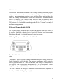
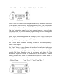
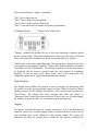
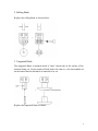
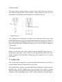
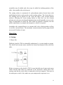
AUTOCUT 7000
USER MANUAL
AMXMAN-96-01 REV 1
AUTOMETRIX, INC.
www.autometrix.com
[email protected]
PH: 530-477-5065
FX: 530-477-5067
Introduction
Your AutoCut 7000 is a precision single layer cutting system that will provide
years of trouble free low maintenance operation, if properly cared for and operated
within the guidelines provided in this manual. This manual is designed to provide
for you all of the technical information you should need to independently maintain
and operate your cutter. When you do require assistance, Autometrix Customer
Service is only a telephone call away.
2
General System Description
Following is an overview of the components of your AutoCut model 7000:
A. Control Software: PlotterPilot and PatternSmith
PatternSmith and Plotter Pilot allow you to import, edit, and nest copies of patterns
drawn with most CAD programs, or developed in PatternSmith. You may nest as
many copies of a pattern as you wish and then plot or cut them.
B. Electronics Cabinet
The Electronics Cabinet contains the controller, interface boards, and drive
amplifiers for each motor. It receives instructions from PlotterPilot through a serial
cable, and translates them into signals to position the carriage and cutting head.
C. Carriage
1. Motors
The AutoCut 7000 carriage has four motors. Two drive the X axis (the length of
the table), one drives the Y axis (the width of the table), and one steers the cutting
blade, called the theta axis. The X and Y axes are directly driven by a pinion
attached to the motor shaft. The pinion can be replaced by loosening the clamping
collar. Each motor is mounted on an eccentric motor mount. To adjust the amount
of pinion engagement, loosen the screws holding the motor mount, and rotate until
the engagement is correct.
2. Rails and Rack
Both X and Y axes use a rack and pinion drive. The racks themselves are oriented
in an inverted position (teeth down) so that dirt, dust, and cutting debris cannot
collect and cause inaccuracies or create excessive drive resistance.
The X rails are structural members attached to the vacuum panel edges. They are
the source of linear accuracy along the X axis, so it is important to avoid
subjecting the rails to excessive force or loading that may distort the rails.
3. Cutting Head
The cutting head includes a pen holder and two steered blade holders. The blade
holders can accept a rolling blade, tangential blade, or rotary punch. The pen and
blade holders are actuated by adjustable pneumatic pressure.
3
4. Limit Switches
There are six limit switches mounted on the carriage assembly. The main purpose
of these switches is to enable the carriage to be stopped automatically, as soon as it
reaches a pre-set maximum position in any direction. These limit switches also
enable the carriage to automatically square itself to the table. The limit switches
operate by emitting a tiny infrared beam, which is made or broken by metal
triggers mounted in different positions on the carriage, or on the table.
The positions of all of the limit switch triggers define the "in bounds" rectangle of
maximum carriage motion.
D. Keypad Display Module (KDM)
The KeyPad Display Module (KDM) provides the operator with local control of
the carriage. It includes a Display Screen, Joystick for Jogging, Pause button, and a
Push Button Keypad. It is divided functionally into four groups.
1. Homing Group:
"Find Home" and "Go Home"
The "Find Home" key is used each and every time the operator powers up the
cutter.
"Find Home" causes the plotter carriage to automatically move slowly towards the
Global Origin (0,0) end of the table. The carriage Auto-Squares itself, setting the
Y-Axis perpendicular to the X-Axis of the table, and setting the cutting blade to
zero degrees. After squaring, the carriage moves to the pre-determined "Global
Origin" starting point, (X,Y = 0,0), and waits for further commands.
"Go Home" instructs the carriage to return from its present position, anywhere on
the table, to the "Global Origin" point (0,0).
4
2. Control Group: "On Line", "Local", "Start", "Pause" and "Cancel".
"Local" means that control of the cutting head and carriage assemblies is exercised
by the operator, using KDM keys, or jogging with the joystick. The host computer
cannot send plotting/ cutting commands while the system is in "Local" mode.
"On Line" relinquishes control to the host computer in order to execute Plotter
Pilot instructions. The operator can still jog the carriage to a new starting point
while in "OnLine" mode.
"Start" is used to initiate the plotting and cutting of a table nested in PlotterPilot.
"Start" will also act as a "resume carriage motion" command after it has been
interrupted by the operator pressing the "Pause" button.
The "Cancel" Button terminates a cutting job that has been interrupted by a
"Pause" button request.
The "Pause" Button is a large diameter red mushroom button, located in the upper
left hand corner of the KDM. When the carriage is in motion and controlled by the
host computer, pressing the "Pause" button will stop the carriage as quickly as
possible. The system remembers where it has stopped, and retains all of the
information required to continue on if instructed to do so. In order to resume
cutting, press the "Start" button. To terminate the job, press the "Cancel" button. A
common use for pause is to change pens.
3. Device Group:
"Pen", "Dev. 1", "Dev. 2", and "Dev. 3"
5
These push buttons are "toggle" commands.
"Pen" lifts or drops the pen
"Dev1" lifts or drops the cutting blade.
"Dev2" lifts or drops the Roto-Punch tool.
"Dev3" is not used, and is available for special programming.
4. Digitize Group:
"Digitize"and "Enter Point".
"Digitize" prepares the machine for use in full scale digitizing of patterns placed
on the cutting surface. This mode communicates with a specific section of Plotter
Pilot, and records the coordinates of the pen or optional laser as a "pointer".
"Enter Point" is used only while Digitizing. The carriage pen is placed over a point
of the pattern being digitized. When the "Enter Point" button is pushed, the current
coordinates are sent to PlotterPilot. The carriage is then moved to the next point to
be digitized and the process repeated until the entire pattern is completely
digitized. To end an entity, press “Enter Point” twice at the same point. The
completed pattern can be exported to PatternSmith for editing.
Digital Display
The Display Screen allows the operator to receive messages or instructions from
the software as to the next appropriate course of action. When the AutoCut 7000 is
initially powered up, the display will indicate to the operator that he must press
"Find Home". The display also relays messages that either the "Pause" or
"Emergency Stop" buttons have been activated, if such is the case. During jogging,
the display shows the present (X,Y) coordinates of the plotting head.
Jogging
Moving the Joystick will cause the carriage assembly to "Jog" in the direction the
control is moved. The Joystick jogging speed is proportional (three discrete levels
slow, medium, fast) to the deflection of the joystick control. The greater the
deflection, the faster the carriage moves. While the Jog Control is primarily for
6
movement of the carriage assembly while "Off line", the operator can "Jog" the
carriage using the joystick while either in "Local" or "On Line" modes, as long as
Plotter Pilot has not received a "Start" instruction.
E. Blade Holders and Pen Holder
The AutoCut 7000 can hold either a rolling circular blade, or a tangential knife
blade. Selection of the roller blade or tangential blade depends upon the material
and patterns to be cut. Most fabrics can be successfully cut with the rolling blade.
Some difficult to cut "high density" materials such as clear acrylics or kevlar
reinforced materials can only be cut using the tangential blade. Also, the rolling
blade cuts a clean circle or radius down to about one half inch radius. If your
patterns have smaller radii, try the tangential blade, which has no restriction on
radius of cut. Both cutting devices should be evaluated when cutting new materials
to determine which yields the best results.
1. Pens
The pen holder can accept most pens up to one half inch (0.5”) in diameter. The
pen holder is raised and lowered using pneumatic pressure. The pen’s pressure is
adjusted by the spring pressure.
To replace a pen, loosen the tightening bolt marked A, insert another pen, and
tighten the tightening bolt.
To adjust the pen pressure and/or height, loosen the two bolts marked B that allow
the holding bracket to slide up or down, move the bracket up for less spring
pressure on the pen, or down for more spring pressure. Moving the bracket down
also allows you to have shorter tipped pens in the holder. Tighten bolts (B) when
you have adjusted your pen allowing about 1/8" compression on the spring when
the pen is in the down position.
7
2. Rolling Blade
Replace the rolling blade as shown below:
3. Tangential Blade
The tangential blade is mounted inside a "shoe" which rides in the surface of the
material being cut. Set the depth of blade below the shoe to a few thousandths of
an inch more than the thickness of material to be cut.
Replace the tangential blade as shown.
8
4. Rotary Punch
The rotary punch is mounted inside a rotating "shoe" which rides in the surface of
the material being punched. Set the depth of blade below the shoe to a few
thousandths of an inch more than the thickness of material to be cut.
5. Cutting Pressure
The cutting pressure adjustment is located on the cutting head. With a new, sharp
blade, most materials can be cut with the cutting pressure set between 18 and 25
psi. A few tougher materials may require up to 32 psi. As the blade gets dull, you
will increase the pressure. When the pressure gets to 35 psi, it is time to change to
a sharp blade.
6. Resharpening Blades
Blades for both the roller cutter assembly and the tangential blade can be resharpened several times, before having to be discarded and replaced with new
blades. Autometrix provides blade re-sharpening and exchange service, as well as
new blades.
F. Vacuum Table
The Vacuum table is constructed of precision aluminum honeycomb core panels to
provide rigidity, which are supported by a steel frame.
The vacuum blower supplies vacuum to manifolds and plenums in order to evenly
distribute the "vacuum" holding force over the entire table surface. Vacuum
blower assembly(s) are positioned either under the table or at a remote location to
eliminate noise. Depending upon table length additional vacuum blower
9
assemblies may be added, and valves may be added for isolating portions of the
table, when smaller jobs are being cut.
The cutting surface is constructed of polycarbonate plastic (lexan) sheets with
small diameter holes evenly spaced over the working surface. The Lexan sheets are
free floating and are placed over the "peak and valley" vinyl vacuum plenum
surfaces. Allowing the Lexan cutting surface to float free over the vacuum
plenums not only prevents thermal distortions that would naturally occur over the
range of temperature in which the 7000 would be required to function, but also
makes replacement very simple and inexpensive, when it is required.
Attached to the vacuum blower is a vacuum relief valve, which provides air flow
to cool the vacuum blower. The maximum vacuum measured on the gauge should
not exceed 90 inches of water.
Operation
A. Startup
1. Power On
While the AutoCut 7000 is technically sophisticated, it is quite simple to operate.
The On/Off and vacuum starter switches are located on the panel at the end of the
table:
Before you power up the AutoCut 7000, be sure that both sets of motor and sensor
cables and the kdm cable are connected to the electronics cabinet and to the
carriage, and that the serial cable is connected to the host computer. Then turn on
the main power switch. Also, make sure your compressed air pressure is on.
10
2. Find Home
When you initially power up, the KDM screen display will prompt you to "Find
Home". Press the "Find Home" command button. The carriage will respond by
moving in the negative Y and negative X directions. When the carriage reaches the
X triggers, it will "AutoSquare" itself to the table, using the limit switches and
triggers. Next, it will align the cutting blade to zero dgrees, and finally move to
the Global Home (0,0) position, at which point it will stop and await further
instructions. The screen display should now read X= 0.00, Y= 0.00.
3. Local and Online modes
You will start in "Local" mode. In this mode, you are free to jog the carriage in any
direction. Caution: don't jog with either cutter in the down position. Before you
can plot or cut under host computer control, you will change to "Online" mode.
When you want to return to Global Home position, press the “GoHome” button.
B. Plotting and Cutting
1. Start Plotter Pilot
You will find complete instructions for the use of Plotter Pilot in Help files, and
the Tutorial. For now, we will open a file which holds nested patterns, called
Testplot.nst. Click on File, then Open, and then double click on Testplot. You will
see patterns in the top portion of the screen, with copies nested on the material
below.
2. Plot/ Plotter Setup/ set com port
The first time you use Plotter Pilot, you need to determine which com port is
connected to the cutter. Click on Plot, then Plotter Setup, and select either com1 or
com2.
3. Roll out material
Very tough materials or small radius curves may require the tangential blade, but
most cutting jobs can be done with either blade type. The patterns in Testplot can
all be cut well with the rolling blade, so for this test, make sure you have the
rolling blade in position A of the cutting head.
11
Roll the material to be cut onto the vacuum table, smoothing wrinkles as much as
possible. Make sure that all the vacuum port holes in the table cutting surface are
covered by the material. If your material doesn’t cover all of the holes, use filler
material to block the open holes. If your material is porous, it will be necessary to
cover the material with a plastic sheet, in order to hold it firmly in place.
Turn on the vacuum blower. The vacuum pressure gauge on the end of the
manifold should read at least 30 inches of water. When all of the holes in the
surface are sealed completely, you can develop 90 inches, however we have found
that you can cut successfully as low as 25 inches. The material you are cutting
should be firmly held to the surface now.
4. Jog to local origin
Jog the pen to the lower left hand corner of the material to be cut. This will become
your “local origin”.
5. Plot/ Current Table (start location and out of bounds)
At the computer, click on Plot, then Current Table, to plot the table shown at the
bottom of the screen. You will see a dialog showing the length and width of
material to be cut. It also shows the maximum X,Y start location. If you jog
beyond those coordinates, there will not be enough room to fit the cutting job on
your table. If you do jog past the max start point, you will get an “Out of Bounds”
error from Plotter Pilot when you try to start.
At the cutter, press “OnLine” to change from local mode to online mode. Notice
that when you do, the computer screen will show a “Start” button. Until you switch
to “Online” mode, it isn’t possible to start a plot/cut job. Now you can press
“Start” at either the computer screen, or at the KDM.
After a one of two second delay, the carriage will move. Plotter Pilot will do any
plotting required, and then switch to cutting. When the job is finished, the carriage
will return to the current “local home”, and wait for your next command.
6. Pause/ Restart/ Cancel
At any time while cutting, you can pause the carriage by pressing the red “Pause”
button to the left of the KDM. You might need to change a pen, or you may find
you have started the wrong job. The KDM will report “Motion Paused”, and wait
for you. There is a second pause button on the far side (echain side) of the carriage.
12
You can either restart the job by pressing “Start” on the KDM, or cancel it by
pressing “Cancel”.
7. Emergency Stop
The Emergency Stop (Estop) is actuated by the large Red button on the main
switch panel at the origin end of the table. This is available for Emergencies, such
as a broken pen or blade, or obstructions. Pressing the Estop is a “dumb stop”...all
position information is lost. After an Estop, you must turn off power to the cutter,
and then reset the Estop button by turning it clockwise. Close Plotter Pilot, wait 15
seconds, then restart the both cutter and Plotter Pilot.
Preventive Maintenance
The most important thing that the machine operator can do is to keep the X rails,
rack, and pinions clean, and free from any accumulation of debris. As such, the
maintenance schedule is quite simple, and as long as it is followed, experience
shows that many years of trouble free operation can be expected.
• Clean X axis rails. Debris can interfere with rail followers.
• Clean X axis rack. Buildup of debris will result in premature wear on pinions.
• Check cutting blade. Dull or damaged blade reduces cutting efficiency and can
damage cutting surface.
• Check E-chain for obstructions, which can cause severe damage to cables and
carriage.
• Blow debris from Cutting Surface.
• Check E-chain. Damage to cables can result in machine down-time.
• Clean Y axis linear rails. Accumulated dirt will cause undue wear.
•
•
•
•
Replace cutting blade. Assuring a sharp blade maximizes cutting efficiency.
Check blade bolt. The blade should feel rigid.
Check X axis pinions. Wear will affect accuracy of movement.
Blow out Cutting Head with compressed air.
•
•
•
•
Replace blade bolt. Longer use invites failure.
Grease vacuum blowers per suppliers instructions.
Replace X Axis felt wipers.
Adjust bottom wheels and pinions.
13
Adjusting the carriage wheels and drive pinion:
Tools required:
• 10 mm end or socket wrench
• 5/8” end wrench
• 5/32” Allen wrench
• 9/64” Allen wrench
• 4 mm Allen wrench
Preparation:
1. Turn on the cutter, and press Find Home, in order to square the carriage.
2. Remove both end covers by removing all four #8-32 (9/64” Allen wrench)
screws shown below.
3. Barely loosen the four #10-32 (5/32” Allen wrench) screws holding the motor
mount in place. These should be just loose enough to allow you to rotate the
motor as far as possible in the counter clockwise direction.
4. Barely loosen the two 10mm hex nuts shown below (the screw requires a 4mm
Allen wrench). These need to be just loose enough to allow you to turn the 5/8”
hex adjuster with a wrench, but no more.
14
Adjusting the Bottom Wheels:
1. Using a 5/8” open end wrench, rotate the Hex Adjusters shown below, until
there is a visible gap between both bottom wheels, and the table rails.
2. For each wheel, rotate the Hex Adjuster until you can feel friction between the
wheel and the rail.
3. Tighten the 10mm hex nuts, while preventing the screws from rotating using a
4mm Allen wrench.
4. Check your adjustment on the bottom wheels: you should be able to rotate
either wheel and move the carriage; alternatively, it you hold the carriage still,
you should be able to rotate either wheel with hand pressure.
Adjusting the Pinions:
1. Holding the pinion in your left hand, and the motor in your right hand, move
the carriage end slightly back and forth. With the motor in the counter
clockwise position, you will feel a small amount of backlash movement in the
pinion.
2. Still holding the pinion in your left hand, rotate the motor mount clockwise
very slowly until you can feel the backlash just disappear.
3. Tighten the motor mount screws.
4. Check all your adjustments again, and then replace the end covers.
15
Appendix
AutoCut files on your computer
In the \Windows directory:
Plotter.dat
PltPilot.ini
holds calibration info for PlotterPilot’s use
holds initialization info for PlotterPilot
In the \Amx directory:
Mx.exe
M960upd.exe
Wmx.exe
M2initst
Kdm4.ini
Moparams
Usercals
Dos comm program
Dos firmware update software
Windows95 comm and firmware update software
Controller init files
Controller kdm files
Controller motion parameters
Controller calibration parameters
In the \Psmith directory:
Psmith.exe
PltPilot.exe
PatternSmith program
PlotterPilot program
Power Requirements
Caution:
Improper or incorrect power connections or voltage levels can impair
performance and could potentially cause severe damage to the system.
The AutoCut 7000 requires multiple power circuits to power the system components. All
electrical power sources and connections should be referred to a qualified licensed
electrician, before connection to the AutoCut 7000. There are three separate power
requirements that must be met in order for the AutoCut 7000 to function properly.
The Host computer
The Electronics Cabinet
The Vacuum Blower Assemblies
110 VAC, 20 Amp, Single (1)Phase
220 VAC, 20 Amp, Single (1)Phase
220 VAC, 30 Amp, Three (3) Phase
In North America, the standard voltages and currents required are readily available,
however, in other parts of the world the power standards may be significantly different. It
is essential to realize that local voltages and standards of regulation can vary
substantially. In order to assure the proper performance of the AutoCut 7000 local
voltages and currents must be measured and the information provided to Autometrix prior
to final assembly and shipment of the equipment. If local line conditions are understood it
may be possible for some of the electrical components to be specially ordered so as to
compensate for them.
16
Shielding of Power Circuits may be required:
Not only are the actual voltages and currents important for proper performance, some care
must also be given to proper electrical routing and shielding. Without the use of separate
conduits and the separation of single and 3 phase power sources signal interference may
occur. To avoid the possibility of signal interference due to stray electromagnetic fields,
the single phase power to the electronics cabinet, and the three phase power to the
magnetic starters and vacuum blowers, should be run in separate conduit and kept at least
12 inches (30 cm) from each other. Attention should be paid, wherever possible, to avoid
running power lines parallel to each other. The single phase and three phase power
sources must always be separate circuits; 30 amp service for the three phase, and 20 amp
service for the 110 and 220 VAC single phase. Power to the electronics cabinet and the
host computer should be line conditioned and surge protected to smooth power
fluctuations.
Tips on Power Conduit Layout
220 VAC three phase power, on its own 30 amp circuit, should be run in metal (shielded)
conduit to a power disconnect and then to the main switch panel switching relays. The
switched 3 phase power output from the power control relays should be routed
underneath the table to each vacuum blower using metal (shielded) conduit. This conduit
is typically hard plumbed, however, the last 2 feet need to be flexible conduit, to allow for
minor adjustments in location of the blower assemblies.
110 VAC single phase power, on its own 20 amp. circuit, conduit shielded, line
conditioned, and surge protected should be provided to the host computer.
220 VAC single phase power, on its own 20 amp. circuit, conduit shielded, line
conditioned and surge protected should be routed to the main switch panel. The switched
220 single phase power can then be routed via conduit, under the table, away from the
three phase power line, to the contact box, mounted on the table frame at mid table in the
immediate proximity of the electronics cabinet.
17