1
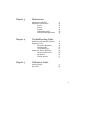
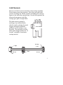
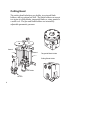
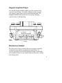
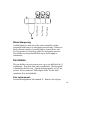
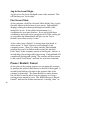
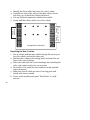
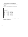
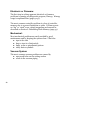
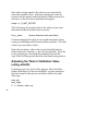
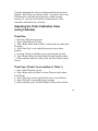
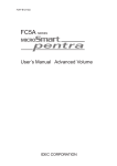
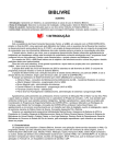
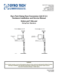
AutoCut
Model M3
Model 7K
User’s Manual
Autometrix Precision Cutting Systems, Inc.
Grass Valley, CA 95945
530/ 477-5065
1
Chapter 1
System Description
Carriage
Limit Sensors
Cutting Head
Keypad/ Joystick
Electronics Cabinet
Cables
Vacuum Table and Cutting Surface
Power Requirements
Chapter 2
System Operation
Startup
Keypad/ Joystick
Jogging
Using the Keypad
Blade Holders
Changing Blades
Cutting Blade Pressure
Blade Sharpening
Pen Holder
Pen Height
Plotting and Cutting
Starting PatternSmith
Material/ Vacuum Hold Down
Local Origin
Plotting the Current Table
Pause/ Restart/ Cancel
Emergency Stop
2
5
7
8
9
9
10
10
11
15
16
17
18
21
21
24
25
25
26
27
27
27
28
28
28
29
Chapter 3
Maintenance
Maintenance Schedule
Adjustment Instructions
Trucks
Pinions
Joystick
Cable Replacement
Cutting Head Replacement
Chapter 4
TroubleShooting Guide
Guidelines and Common Problems
Diagnostic Tools
Electronics Backplane
Warning lights
Using Wmx95.exe
Symptoms, Causes, Remedies
Electrical/ Electronics
Mechanical
Vacuum System
Chapter 5
31
35
35
37
39
40
43
47
49
49
50
51
58
58
69
75
Calibration Guide
Carriage Square
Theta Axis
77
78
3
4
Chapter 1
System Description
Your AutoCut system consists of the vacuum table with
integrated linear support rails, light weight carriage and cutting
head, electronics cabinet, and cables. You control the system
from your host computer through PatternSmith software.
Carriage
The AutoCut carriage is made of aluminum and carbon fiber for
the lightest possible weight. Lighter weight means lower forces
on the system, which means less wear and improved reliability.
5
Motors
The AutoCut carriage has four motors. Two drive the X axis
(the length of the table), one drives the Y axis (the width of the
table), and one steers the cutting blade, called the theta axis.
The X and Y axes are directly driven by a pinion attached to the
motor shaft.
Y Motor
Theta Motor
XB Motor
XA Motor
Rails and Rack
Both X and Y axes use a rack and
pinion drive. The racks themselves
are oriented in an inverted
position (teeth down) so that dirt,
dust, and cutting debris cannot
collect and cause inaccuracies or
create excessive drive resistance.
The X rails are structural members
attached to the vacuum panel
edges. They are the source of
linear accuracy along the X axis, so Rail
it is important to avoid subjecting
the rails to excessive force that
could distort the rails.
6
Rack
X Motor
Limit Sensors
There are six limit sensors mounted on the carriage assembly.
These sensors serve two purposes. First, they are used in the
process of finding the ‘Home’ position and making the carriage
square to the table when powered up. Second, they generate an
alarm and emergency stop if the
carriage goes past its range limits.
The limit sensors operate by
emitting a tiny infrared beam,
which is made or broken by metal
triggers mounted in different
positions on the carriage, or on
the table. The positions of all the
limit switch triggers define the “in
bounds” rectangle of maximum
carriage motion.
Limit Sensor
XA High
Y High
XB Low
Y Low
Theta
XA Low
7
Cutting Head
The cutting head includes a pen holder, two steered blade
holders, and an optional air drill. The blade holders can accept
two types of rolling blades, tangential blades, a rotary punch or
a notch tool. The pen and blade holders are actuated by
adjustable pneumatic pressure.
Cutter 2
Cutter 1
Tangential Blade Holder
Rolling Blade Holder
Pen Holder
Air Drill
8
Keypad/ Joystick/ Pause
The KeyPad Display Module (KDM) gives the operator local
control of the carriage. It includes a display screen, joystick
(for jogging), pause button and a push button keypad. The
keypad is divided functionally into four groups: homing,
control, devices, and digitizing.
Display
Joystick
Pause
Button
Keypad
Electronics Cabinet
The electronics cabinet contains the power supply, controller,
interface boards and drive amplifiers for each motor. It
receives instructions from PatternSmith through a serial cable
and translates them into the signals which position the carriage
and cutting head.
9
Electronics Cabinet Back
Keypad
Cable
Host
Cable
Signal
Cables
Motor
Cables
Cables
Moving cables for the x and y axes are enclosed in Energy
Chain, or ‘E-Chain’. E-Chain snaps open for easy replacement
of cables (see Maintenance Chapter).
Vacuum Table and Cutting Surface
The vacuum table is constructed of aluminum and honeycomb
core panels for rigidity. These panels are supported by a steel
frame table base.
The vacuum blower applies suction to the entire table, evenly
holding the material in place. The vacuum blower assembly is
positioned under the table, or at a remote location to eliminate
noise. Additional vacuum blower assemblies may be needed
when the table is longer than 40 feet. Valves may be added,
10
allowing you to use a reduced portion of the table for a smaller
cutting job. Noise buffers may be placed around blower.
The cutting surface is constructed of polycarbonate plastic
(lexan). Small diameter holes are evenly spaced over the
cutting surface. The lexan cutting surface is free floating and is
placed over the “peak and valley” vinyl vacuum plenum
surfaces. Allowing the lexan cutting surface to float freely over
the vacuum plenums eliminates problems that could be caused
by thermal expansion. It also makes replacement quick and
simple.
Attached to the vacuum blower is a vacuum relief valve. This
provides air flow to cool the vacuum blower. The maximum
vacuum on the gauge should not exceed 110 inches of water.
Power Requirements
The AutoCut requires multiple power circuits to power the
system components. All electrical power sources and
connections should be referred to a qualified licensed
electrician, before connection to the AutoCut. There are three
separate power requirements that must be met in order for the
AutoCut to function.
Host computer:
110 VAC, 20 Amp, Single (1) Phase
Electronics cabinet:
208 / 220 / 235 / 240 VAC, 20 Amp, Single (1) Phase
Vacuum blower:
220 / 440 VAC, 40 Amp, Three (3) Phase
11
Shielding of power circuits may be required:
Care must be given to proper electrical routing and shielding.
Without the use of separate conduits and the separation of
single and 3 phase power sources, signal interference may
occur. To avoid the possibility of signal interference due to
stray electromagnetic fields, the single phase power to the
electronics cabinet, and the 3 phase power to the magnetic
starters and vacuum blowers, should be run in separate conduit
and kept at least 12 inches (30 cm) from each other. Whenever
possible, avoid running power lines parallel to each other. The
single phase and 3 phase power sources must always be
separate circuits: 40 amp service for the 3 phase, and 20 amp
service for the 110 and 220 VAC single phase. Power to the
electronics cabinet and the host computer should be line
conditioned and surge protected to smooth power fluctuations.
Tips on Power Conduit Layout
The host computer requires110 VAC single phase power, on its
own 20 amp circuit, conduit shielded, line conditioned, and
surge protected.
The AutoCut carriage and electronics cabinet need 220 VAC
single phase power, on its own 20 amp circuit, conduit
shielded, line conditioned, and surge protected. From the main
switch panel, the 220 single phase power can then be routed via
conduit, under the table and away from the three phase power
line. It then routes to the contact box, mounted on the table
frame at mid table in the immediate proximity of the
electronics cabinet.
The blower assembly uses 220 VAC three phase power, on its
own 40 amp circuit. This should be run in metal (shielded)
12
conduit to a power disconnect and then to the main switch
panel switching relays. The switched 3 phase power output
from the power control relays should be routed underneath the
table to each vacuum blower, using metal (shielded) conduit.
This conduit is typically hard plumbed, however the last 2 feet
need to be flexible conduit, to allow for minor adjustments in
location of the blower assemblies.
13
14
Chapter 2 System Operation
Startup
Power On
The On/Off and vacuum starter switches are located on the
panel at the end of the table. Before you power up the AutoCut,
make sure that:
Both sets of motor and sensor cables are connected to the
electronics cabinet and the carriage.
z The KDM cable is connected to the electronics cabinet.
z The serial cable is connected to the host computer.
z The compressed air pressure is turned on.
z
On/Off
Emergency Stop
Air Controls
Tool Holder
Vacuum Starter(s)
15
Find Home
When you initially power up, the KDM screen display prompts
you to “Find Home”. Press the “Find Home” keypad button.
The carriage responds by moving in the negative Y and negative
X directions. When it reaches the X triggers, the carriage
“auto-squares” itself to the table, using the limit switches and
triggers. Next, it aligns the cutting blade to zero degrees, and
finally moves to the global home (0,0) position, at which point
it stop and await further instructions. The screen display now
reads x= 0.00, y= 0.00.
Local and Online modes
You will start in “Local” mode. In this mode, you are free to jog
the carriage in any direction. Caution: Do not jog with either
cutter in the down position! To plot or cut under host computer
control, change to “Online” mode. When you want to return to
Global Home position, press the “GoHome” button.
Keypad / Joystick / Pause
Keypad Display
The Display Screen shows messages or instructions about your
next course of action. When the AutoCut is initially powered
up, the display indicates that the operator must press “Find
Home”. The display also relays messages when either the
“Pause” or “Emergency Stop” buttons have been activated.
During jogging, the display shows the present (x,y) coordinates
of the pen.
16
Using the Joystick to Jog
When you start the system and press “home”, the carriage
moves to the “global origin” where both x and y equal zero.
You can start your cutting job at the global origin, or you may
want to start your cutting job at another location. Use the
joystick to move your carriage to any start location, being
careful to make sure the entire job can still fit on the table.
Moving the joystick causes the carriage assembly to “jog” in the
direction the control is moved. The joystick jogging speed is
proportional (three distinct speeds: slow, medium, fast) to the
movement of the joystick control. The greater the movement,
the faster the carriage moves. The Jog Control is primarily for
movement of the carriage assembly while “Off line”. The
operator can, however, “jog” the carriage using the joystick
while either in “Local” or “On Line” modes, as long as
PatternSmith has not received a “Start” instruction.
Using the Pause Button
The Pause Button is a large diameter yellow mushroom button,
located to the left of the KDM. When the carriage is in motion
and under control of the host computer, pressing the ‘Pause’
button will immediately stop the carriage. The system
remembers where it stopped, retaining the information needed
to resume cutting, if asked. To resume cutting, press the ‘Start’
button. To terminate the job, press the ‘Cancel’ button. The
Pause button can be used to change pens, blades, or check cut
depth. It is also your means to quickly stop the AutoCut
carriage if a bystander enters it’s range of motion.
17
Using the Keypad
Homing Group:
The Find Home key is used every time you power up the
cutter. It causes the plotter carriage to automatically
move slowly towards the global origin (0,0) end of the
table. The carriage auto-squares itself, setting the y-axis
perpendicular to the x-axis of the table, and setting the
cutting blade to zero degrees. After squaring, the
carriage moves to the pre-determined ‘global origin’
starting point, (x,y = 0,0), and waits for further
commands.
Go Home sends the carriage to its previous start point
on the first press, and to the global origin point (0,0) the
second time it is pressed.
Precision Cutting Systems
Find
Home
Go
Home
18
Control Group:
On Line relinquishes control to the host computer in
order to execute PatternSmith instructions. You can still
jog the carriage to a new starting point while in “On
Line” mode.
Local places the operator in control of the machine. The
host computer cannot send plotting or cutting
commands while the system is in this mode.
Start initiatse the plotting and cutting of a table nested
in PatternSmith. ‘Start’ will also act as a “resume
carriage motion” command after operation has been
interrupted by the ‘Pause’ button.
Cancel terminates a job that has been interrupted by a
‘Pause’ button request.
Precision Cutting Systems
Online
Local
Dgtz
Start
Cancel
19
Device Group:
These push buttons are “toggle” commands.
Pen: lifts or drops the pen
Dev1: lifts or drops the cutting blade
Dev2: lifts or drops the Roto-Punch tool.
Dev3: Lifts or drops the Air Drill, or can be available for
special programming.
Pen
Dev1
Dev2
Dev3
Digitize Group:
Digitize makes your AutoCut a full scale digitizer for
patterns placed on the cutting surface. The pen can be used
as a “curser” or pointer. We recommend, however, that you
use a laser pen as your pointer devise. This eliminates the
need to raise and lower the pen.
Enter Point sends the current coordinates to PatternSmith.
Move the carriage to the next point to be digitized and
repeat the process until your pattern is completely digitized.
To end a pattern element, press “Enter Point” twice at the
same point. The completed pattern can be edited in the
PatternSmith editor.
20
Blade Holders
The AutoCut has two steered blade holders. Each holder can
accept a rolling circular blade, a tangential knife blade, a
notching blade, or a hole punch. Select the rolling blade or the
tangential blade based on the material and patterns to be cut.
Most fabrics can be successfully cut with the rolling blade.
Some “high density” materials, such as clear acrylics or kevlar
reinforced materials, require the tangential blade. The rolling
blade cuts a clean circle or radius down to about one half inch
radius. Smaller radii can be cut with the tangential blade.
When cutting a new material, test both cutting devices to
determine which will provide the best results.
Tell PatternSmith which blade you have in each device. From
the Project Window, click PlotÖPlotter SetupÖDevices. Set the
number of plotting or cutting devices in the Total Devices
Selector box. For each device, select the blade type that you are
using. With the optional air drill, an AutoCut can simultaneously carry four devices - pen, cutting blade, notching tool, and
punch. On your pattern, set elements to Plot Type Cut1 or Plot
Type Cut2 on the Attribute Toolbar in the Editor Window.
Changing Blades
Rolling Blades
Change the rolling blade as shown. Important: Olfa blades
and carbide blades use different spacers.
Olfa Blades
The Olfa blade uses two differently styled spacers. One
spacer has three raised nibs around the center hole. The
other has a recessed ring aroung the center hole. First,
21
er
Sp
ac
Sp
ac
er
make sure the triangular center hole of the Olfa blade is
nestled firmly onto the raised nibs of the nibbed spacer.
Then center the recessed spacer on the blade. Place the
blade changing tool on the end of the shoulder bolt.
While carefully holding the blade/spacer unit between
the arms of the blade holder, insert the narrow end of
the blade changing tool through the bearing, the
blade/spacer unit, and the second bearing. Push the
shoulder bolt through until it stops. (The blade
changing tool will drop off.) Attach the nut to the
shoulder bolt.
Carbide Blades
A carbide blade uses two identical spacers. Center the blade
between the two spacers and then use the blade changing
tool to attach the blade/spacer unit, as described above.
22
Blade Change
Tool
Tangential Blades
The tangential blade is mounted
inside a “shoe” which rides on the
surface of the material being cut.
The depth of blade, or distance
below the shoe, should be set to a
few thousandths of an inch more
than the thickness of the material to
be cut. Replace the tangential blade
as shown. Loosen the collar clamp
bolt with your 3/16” T-handled allen
wrench. Unscrew the collar clamp.
Using a 5/64” allen wrench, loosen
the set screw which anchors the
tangential blade. Replace the blade,
making sure that the flat side of the
blade post is facing the center of the
blade holder. Tighten the set screw.
Replace the collar clamp, screwing it
on to the proper blade depth.
Tighten the collar clamp bolt.
Teflon
Shoe
Collar
Clamp
23
Notch Blade
The notch blade is mounted in the same style blade holder as
the tangential blade. Replace the notch blade in the same
manner.
Rotary Punch
The rotary punch is mounted inside a rotating “shoe” which
rides on the surface of the material being punched. Set the
depth of blade below the shoe to a few thousandths of an inch
more than the thickness of material to be cut. Replace the
rotary punch in the same manner as a tangential blade.
Cutting Pressure
The cutting pressure adjustment is located on the table base,
near the on/off switch. With a sharp blade, most materials can
be cut with the cutting pressure set between 20 and 35 psi.
Tougher materials may require up to 40 psi. As the blade gets
dull, you will need to increase the pressure. When the pressure
gets to 50 psi, it is time to replace your blade.
24
Pen Pressure
Dev1 Pressure
Dev2 Pressure
Blade Sharpening
Carbide blades for both the roller cutter assembly and the
tangential blade can be re-sharpened several times. When you
have collected a batch of 50 used blades, contact Micro 100
Tool Corporation (1-800-635-3080) for sharpening services.
New blades can be purchased from an in-stock supply at
Autometrix.
Pen Holder
The pen holder can accept most pens, up to one half inch (0.5”)
in diameter. Pens flow rates vary considerably. Plotting speed
is limited by the flow rate. Typical plotting speed is 15-30” per
second. We recommend “Fisher Space Pens” for the most
consistent flow and reliability.
Pen replacement:
Loosen the adjustment bolt marked ‘A’. Remove the old pen,
25
insert a new pen, and tighten the adjustment bolt.
Height and Pressure Adjustments:
Loosen the two bolts (marked “B”) that allow the holding
bracket to slide up or down. Move the bracket up for less
spring pressure on the pen, or down for more spring pressure.
Adjust your pen to allow for 1/8” compression on the spring
when the pen is in the down position. Tighten the bolts (B).
Adjusting the holding bracket up and down allows for the use
of pens with different length tips.
Adjust the pen down speed with a small screwdriver at C.
A
0.125”
B
26
C
Plotting and Cutting
Starting PatternSmith
Complete instructions for using PatternSmith are found in the
PatternSmith User Manual, help files, and the tutorial cd. Click
FileÖOpen, and then double click on “nest.pat”, a sample
training pattern. Patterns are displayed in the top portion of
the screen, with copies nested on the material below.
Plotter Setup
The first time you use PatternSmith, you need to determine
which com port is connected to the cutter, what blades are
installed on the cutting devices, and the table length. Click Plot
Ö Plotter Setup to enter this information. See the
PatternSmith User Manual for details.
Spreading Material / Vacuum Hold Down
Roll your material onto the vacuum table, smoothing wrinkles
as much as possible. Make sure all the vacuum port holes in
the cutting surface are covered by the material. If your
material doesn’t cover all of the holes, use a filler material to
block the open holes. Porous material must be covered with a
plastic sheet, to hold it firmly in place.
Turn on the vacuum blower. The vacuum pressure gauge on
the end of the manifold should read at least 30” of water.
When all of the holes in the surface are sealed completely,
vacuum pressure can rise to over 100”. We have found,
however, that you can cut successfully with pressure as low as
25”.
27
Jog to the Local Origin
Jog the pen to the lower left hand corner of the material. This
will become your “local origin”.
Plot Current Table
At the computer, click PlotÖCurrent Table (hotkey F10), to plot
the table shown at the bottom of your screen. PatternSmith
displays a dialog box showing the length and width of the
material to be cut. It also shows the maximum (x,y)
coordinates for your start location. If you jog beyond those
coordinates, there will not be enough room to fit the cutting job
on your table and PatternSmith will give you an “Out of
Bounds” error when you try to start.
At the cutter, press “OnLine” to change from local mode to
online mode. A “Start” button is now displayed on the
computer screen. (Note: For safety reasons, PatternSmith
requires that you be in Online mode to start the AutoCut.)
Press “Start” at the computer screen or the Keypad. After a 1-2
second delay, the carriage will begin moving. PatternSmith will
complete all plotting and cutting. The carriage will then return
to the current “local home”, and wait for your next command.
Pause / Restart / Cancel
At any point in the cutting process, you can pause the carriage
by pressing the yellow Pause Button to the left of the keypad. A
second Pause Button is located on the opposite side of the
carriage (e-chain side). The Pause Button is a safety feature,
but can also be used to allow for a pen change, or to stop a
cutting process started in error. The KDM will report “Motion
Paused”, and wait for further instructions. Pressing “Start” on
28
the KDM restarts the job. Pressing “Cancel” ends the job.
Emergency Stop
The Emergency Stop (e-stop) is the large red button located on
the main switch panel at the origin end of the table. This is
available for emergencies such as a broken blade or an
obstruction on the table. When the e-stop button is pressed, all
position information is lost. Turn off the power to the cutter
and reset the e-stop button by turning it clockwise. Close
PatternSmith, wait 15 seconds, and restart the cutter and
PatternSmith.
29
30
Chapter 3 System Maintenance
Maintenance Schedule
The AutoCut carriage, x and y rails, rack, sensors, and pinions
must be kept clean and free from any debris. The maintenance
schedule is simple and, if followed, will ensure that your
AutoCut provides you with many years of trouble-free
operation.
PRECAUTIONS:
z Turn off power to the system before doing any maintenance.
z Never stand on vacuum table top.
z Keep material rolls off of the cutting table when the carriage
is moving. If the carriage hits a roll of material (or other
objects), it can cause extensive damage.
z Keep scrap or waste material from getting caught along the
sides of the carriage or in the x-axis e-chain. Anything
(material, plastic coverings, tape, etc.) that comes between
the extrusions and the moving carriage may cause damage
to the system.
z Keep all heavy equipment and supplies (forklifts, hoists,
rolls of material, pallets, etc.) away from the table.
Bumping the table with force can cause it to lose calibration
or could cause severe damage.
z Protect the machine and yourself from static discharge with
static mats and straps. Always ground yourself before you
handle electronic components.
31
Daily (every 8 hours of use)
z Clean x axis rails. Debris will interfere with the
system’s performance.
z Clean x axis rack. Buildup of debris will cause
premature wear on pinions.
z Clean y axis linear rail. Accumulated dust will cause
unnecessary wear.
z Check cutting blade for wear. Dull or damaged blades
reduce cutting efficiency and may cause unnecessary
wear to the cutting surface.
z Check e-chain for material or obstructions. These can
cause severe damage to cables and carriage.
z Clean the cutting surface by blowing it off with
compressed air. This will help maintain vacuum
pressure.
Weekly (every 40 hours of use)
Check e-chain for debris, damaged cables, or overly
twisted wires that can cause system down time.
z Wipe the x and y axis linear rails down with a drop of
3-in-1 oil on a soft cloth.
z Replace cutting blade. Sharp blades maximize cutting
efficiency.
z
32
Monthly (every 160 hours of use)
z
z
z
z
z
Check blade bolt. The blade should feel rigid, with no
blade wobble.
Inspect Olfa blade holder, if applicable. Blade should
not move from side to side. If it does, replace the
blade holder.
Check x and y axis pinion gears. Pinion wear will
affect the system’s accuracy of movement. Adjust
pinion engagement, if necessary, following instructions below.
Clean system by blowing dust, lint, and material out of
the carriage with compressed air. Clean the limit
sensors with Q-tips so they are free of lint and dust.
Clear the cutting surface holes by blowing them with
compressed air. This will ensure good vacuum
pressure.
Annually (every 2000 hours of use)
z Replace the rolling blade holder’s bolt. Prolonged use
may cause the blade to wobble and result in
inaccurate cutting.
z Grease vacuum blowers, following the manufacturer’s
instructions.
z Rotate or flip the cutting surface, as needed.
z Adjust x axis carriage trucks and pinions, following the
instructions below.
33
Every Two Years (or more)
z Replace Lexan cutting surface.
z Replace the x axis and y axis wiring harnesses (in the
e-chains).
z Replace and adjust x axis and y axis pinion gears,
using instructions that follow.
MAINTENANCE NOTE:
If the machine starts making an unusual noise, try to determine
the source of the noise. This may be the first warning sign of a
worn or damaged part. Replacing the part or returning it to
Autometrix for repair may save you additional damage.
Regular maintenance reduces down time and allows you to
schedule that down time.
34
Adjustment Instructions
Adjusting the Carriage Trucks
Tools required:
5/32” Allen wrench
3/32” Allen wrench
1/2” Open-end wrench
Phillips head screw driver
Loctite #222MS
Preparation:
To adjust the carriage trucks, you need to remove the carriage
from the table and the support trucks from the end plates.
Carriage Removal:
1. Turn cutting machine off.
2. Turn off the air the control panel.
3. On the XB side of the carriage, detach the three air lines at
the quick disconnects. Detach the cables.
4. Remove the XA and XB end caps at the origin end of the
table. (The origin end is the end where the (0,0) point is
and the where the control panel is located.)
5. Remove the XA and XB roll pins at the origin end of the
table.
6. Remove the cutting blades, punch, or notch tool from the
devices.
7. Using two people, roll the carriage off the origin end.
35
Removing Carriage Trucks from End Plate:
1. Remove the end cover on the carriage, loosening the 1/4turn fasteners with a Phillip’s head screwdriver.
2. Remove the support trucks by unscrewing the 3/16” Allenhead truck mounting screws.
Lock Nut
Adjusting Screw
Adjustment:
1. Loosen the lock nut on the center wheel by rotating counterclockwise, while holding the center screw stationary.
2. Place the truck assembly into its track. You may need to
rotate the adjusting screw to allow the center wheel to fit
into the railway.
3. Rotate the adjusting screw to adjust the tightness of the
truck in its track. The wheel needs to be rotated so that it
moves up toward the top side of the track. When adjusted
properly, the truck will not rock in the rail, but still moves
easily.
4. Tighten the lock nut. Push the truck up and down the rail.
It should move freely. If not, it is too tight and needs to be
readjusted.
5. Reinstall each truck on its endplate, with the arrows
36
pointing down. Leave the trucks loosely attached until you
put the carriage back on the table. After mounting the
carriage, tighten the truck screws.
Adjusting the Drive Pinions
The x and y-axis motors are mounted on eccentric motor
mounts. These enable you to adjust the pinion engagement by
simply rotating the motor. Rotating the motors clockwise
raises the pinion, decreasing backlash. Rotating them counterclockwise, lowers the pinion, increasing backlash. The goal is
to come as close as possible to eliminating backlash, without
the pinion engagement being too tight.
A
GEARS ON
OPPOSITE SIDE
A
A
Pinion
A
Less Backlash
More Backlash
37
Tools Required:
5/32” Allen wrench
Phillips head screw driver
Preparation:
1. Turn off the cutter.
2. Remove the end covers.
Backlash Adjustment:
1. Loosen the motor mount screws (labeled A), and rotate the
motor as far as possible counterclockwise to get maximum
backlash.
2. Holding the motor, move the carriage end slightly back and
forth. You will feel the backlash clicking as the pinion
touches the rack at each end of travel.
3. Still holding the motor in one hand, rotate the motor mount
very slowly clockwise, until you can feel the backlash just
disappear.
4. Tighten the motor mount screws (A).
5. Check one more time, and then replace the end covers.
Drive Pinion Replacement
When your pinions become worn, you can easily replace them.
The x and y axis drive pinions are held on the motor shaft by
clamping collars.
38
To replace the pinions:
1. Remove the x-motor from the end plate, or the y-motor
from the y-cage assembly, by removing the four motor
adjustment screws.
2. Observe the position of the worn pinion on the motor shaft.
Note how far the pinion extends beyond the end of the
motor shaft.
3. Remove the worn pinion by loosening the clamping collar
and sliding the pinion off the motor shaft.
4. Replace the worn pinion with a new one, and assemble in
the reverse order. Make sure the pinion extends beyond the
end of the motor shaft by the same amount as the old
pinion.
5. Adjust the pinion engagement.
Adjusting the Joystick
If your carriage begins to creep slowly in any direction, the
joystick may need to be recalibrated. There is a ‘dead band’ in
the center of the x and y travel, and it is easily adjusted.
39
1. Remove the end cover from the
keypad side of the carriage.
2. Using a small Phillips head
screwdriver, loosen the locking
screw shown.
3. Move the potentiometer body
back and forth until you get
motion in either direction.
4. Then center the potentiometer
within that range, and gently
tighten the locking screw.
Replacing Y Axis Cables
We recommend replacement of your y axis cables every two to
three years, and your x axis cables every four years. You will
get a wiring diagram with your new cable set.
Preparation:
1. Turn the power off and remove the power cord from the
electronics cabinet.
2. Remove the end cover from the XB end of the carriage.
3. Remove the cutting head cover.
At the Cutting Head:
1. Identify the three cables that exit the e-chain, and their
terminations.
40
Cutting Head End
Air Fittings
Terminal Strip
Cable 1
Cable 2
Cable 3
pins 1-13
pins 14-20
pins 21-27
2. Carefully cut each of the wires in the three cables, about 1
inch from the terminal strip. Leave enough wire to identify
the color code. Be careful not to cut any other wires.
3. Remove all the air lines from their fittings, and label each
line and fitting.
4. Remove the two screws that hold the e-chain to the cutting
head.
5. Lay the e-chain out flat.
At the Carriage End:
1. Identify the three cables that exit the e-chain, and their
termination points.
41
Cable 2
pin 5-11
Cable 1
pins 4-12
Cable 3
pin 12-18
2. Identify the three cables that enter the y axis e-chain.
3. Carefully cut each of the wires in the three cables, about 1
inch long, as you did at the Cutting Head end.
4. Cut any cable ties required to release those cables.
5. Gently pull these three cables out of the e-chain.
Carriage End Connections
Replacing the New Y cables:
1. One at a time, feed the three cables through the access port,
into the e-chain, and out the other end.
2. Reattach the e-chain at the cutting head, and attach the air
lines to the correct fittings.
3. Select the cable with the correct markings and, matching the
color code, replace each wire, one at a time.
4. Be careful to not pinch the wire insulation in the terminal
strip connection.
5. Make sure that all cables are clear of moving parts and
install cable ties as needed.
6. Power up the machine and press “Find Home” to verify
success.
42
Removing and Replacing the Cutting Head
If any of the device cylinders on your cutting head get bent or
damaged, you will need to send it back to Autometrix for
repair. Removal of the cutting head is simple. Your cutting
head will be returned rebuilt and recalibrated.
Tools required:
5/32” Allen wrench
Small slotted screwdriver
Preparation:
Before doing any work on the cutting head, turn the power off
and remove the power cord from the electronics cabinet.
Disconnect the compressed air lines to the machine and remove
all the cutting tools.
Cutting Head Removal Instructions:
1. Disconnect the theta motor wires from the round amp
connector or the white plastic terminal strip. Cut any cable
ties necessary to remove this wiring harness.
2. Disconnect the theta limit sensor wire by gently pulling the
four pin wire connector apart. This will leave four flat pins
sticking out of the top of the limit sensor. Be careful to not
damage the pins.
3. Mark your air lines with tape or a pen to make sure you
reconnect the lines in the proper locations. Then disconnect
the air lines from the cutting head at the quick disconnects
on the cylinders. Push the outer flange and pull on the tube
to remove the line.
43
B
A
4. Remove the bottom three #10-32 cap screws (A above) that
attach the cutting head to the rolling cage.
5. Remove the top three #10-32 cap screws that are located on
the top cutting head plate (B above).
The Cutting head should now be fully separated from the
cutting machine. It should consist of two air cylinders, a limit
sensor, theta motor with wires, a pen holder, and the three
gears on top.
44
Cutting Head Replacement Instructions
1. Place the cutting head in position, aligning the top three
#10-32 holes in the cutting head with the three threaded
holes in the rolling cage.
2. Start the three #10-32 screws into the top of the cutting
head.
3. Start the three lower #10-32 screws that attach the base of
the cutting head to the rolling cage.
4. Tighten all six screws to approx. 30 in-lbs.
Connect Wiring and AirLines
1. Route the theta motor wire harness around all the moving
parts of the cutting head and reconnect.
2. Connect the theta limit sensor wire by gently pushing the
four pin wire connector onto the sensor. Caution: this
connector will only go on one way so check the direction of
the connector and pins to be sure they are aligned. Do not
force the connection.
3. Connect the air lines to the appropriate air tool by pressing
the tubes into the quick connect fittings.
Recalibration
The theta offset values stored in the controller and used for
homing must be updated for the new cutting head values.
1. Note the two numbers on a dot on top of the theta gear.
The top number is theta1 and the bottom is theta2.
2. In an editor (such as Notepad or Wordpad), open the
usercals file found in your \amx folder.
3. Change the theta offsets in the Homing section of the file as
shown below. Theta1 is the third from the bottom, and
45
theta2 is second from the bottom in that section.
4. Save your changes to the usercals file.
5. Start the Wmx95.exe program, also found in your \amx
folder.
6. Press the F1 key and download the usercals file to the
controller.
(file: c:\amx\usercals)
/* Homing Offsets */
2.650
0.000
0.200
1.900
8.75
2.05
0.2787
0.0040
0.0160
105
106
107
108
13
14
15
16
23
set_float
set_float
set_float
set_float
set_float
set_float
set_float
set_float
set_float
` cut_x_offset
` cut_y_offset
` cut2_x_offset
` cut2_x_offset
` x_limit_offset
` y_limit_offset
` t_limit_offset
` t2_limit_offset
` xsquare_offset
Complete instructions for wmx95 and controller files are found
in Chapter4: TroubleShooting.
46
Chapter 4 TroubleShooting
TroubleShooting Guidelines
The TroubleShooting Guide is divided into four sections:
Software, Electrical or Firmware, Mechanical, and Vacuum.
Before calling us, write down all of your symptoms and the date
when the problem started. We will need as many details as
possible. Even though you may have lots of symptoms that
don’t seem related, the problem usually narrows down to a
single component that is not functioning.
Many common problems are easy to solve or avoid.
Software:
The most common software problems involve Com Port errors.
First, make sure the Com Port cable is plugged in. If it is, set
the Com Buffer sizes lower:
1. Click Start > Settings > Control Panel.
2. Double click System, then select the Device Manager tab.
3. Click the plus beside Ports, then double click the port you
want to set.
4. Select the Port Setting tab, then click the button labelled
Advanced.
5. Move both slider bars to the lowest setting.
If you experience a system crash, or a General Protection Fault
error, go the the Control Panel, and disable Power
Management. This resolves almost all software problems.
47
Electronic or Firmware:
The first step in solving apparent electrical or firmware
problems is running our diagnostic program, Wmx95. Wmx95
usage is explained later (pages 51-57).
The most common controller problem is a loss of controller
memory due to a power fluctuation or spike. If Wmx reports
an “fsp” or “stack” error, reload moparams and usercals as
described on Section J: Rebuilding Flash Memory (page 55).
Mechanical:
Most mechanical problems are easily avoided by good
maintenance and by keeping the system clean. Check for:
z tape in the rails
z dust or tape in a limit switch
z badly worn or misadjusted pinions
z sticky device cylinders
Vacuum System:
The most common vacuum problems are caused by
z uncovered holes on the cutting surface
z a leak in the vacuum piping
48
Diagnostic Tools
1. Electronics Cabinet Backplane
5 volts test points
130 V GND
130 VDC
+5V
24V GND
XA AXIS
130 Volt
Test
THETA
Y ALARM
XA ALARM
XB ALARM
PAUSE
E-STOP
PAUSE
E-STOP
Y HI
Y LO
THETA
XB LO
XA LO
XA HI
+ 24V
XA ALARM
XB ALARM
Y ALARM
THETA ALARM
Motor
Alarms
Limit LEDs
XA LO
XA HI
Y LO
Y HI
THETA
XB LO
24 volts test points
If you are having electronics problems, you will need to
measure voltages and check warning lights. This can be done
on the electronics cabinet backplane (PC board).
XB AXIS
Y AXIS
GND
LAMP
THETA AXIS
Motor Drives
Controller
49
Warning Lights
Check the state of all sensor LEDs and motor alarms is one of
the first diagnostic steps. The status of each limit sensor is
shown on the backplane. If a limit sensor is not working
properly, or is just dirty, its green LED will be turned off. This
lets you easily identify which limit sensors are malfunctioning.
The alarm status for each motor drive is also shown on the back
plane. Motor problems trigger an alarm and a system-wide
emergency stop.
In addition to the motor alarm LEDs on the backplane, each
drive has diagnostic status lights to give more information
about the cause.
Green
Red
Ready
Motor Cable Short
Over Temp
Over Voltage
Under Voltage
50
Using Wmx95.exe for Diagnostics
Wmx95.exe is a diagnostic tool that lets you communicate
directly with the controller of your cutting system. You can use
Wmx for intercepting error messages, calibration, and
downloading init files to the controller. It reads its setup
information from an associated config.mvr file. You will find
both files in your c:\amx folder.
A. Setting the Com Port
Before using Wmx95, set the correct ComPort in the file
config.mvr. The last few lines of the config.mvr file are
shown below. Bring it into any text editor (such as Notepad
or Wordpad) and change the third line from the bottom to
the Com pPort you will be using. Then save the config.mvr
file.
MACHINE_MASK_FLAG 11
FILE_ID *.MIF,*.TIF,*.PCX,*.CNC,*.RUN,*.PLT,*.DXF,*.EVN,
MDI_OPTS 2
PORT COM2
PARM_VARS 50.0000 0.0000 0.0000 0.0000 0.0000
SYSTEM_FLAG 617
If you are unsure which Com Port to use, start
PatternSmith2002 and click on Plot > Plotter Setup and see
which port you have been using.
B. Starting Wmx95.exe
In Windows Explorer, double click on Wmx95.exe to start
the program. A new window opens, showing a divider bar
51
near the bottom. Turn on your cutter. If it is already on,
type COLD and press Enter to restart the controller. You
will see the following sign-on message.
UCito K520 V2.00n C100
8M RAM installed
Can0: 180224, chan1: 512
MCIF V4.26k, FPGA M11V2-GL-KN
KDM V4.26k <c> 2001 etc
Loading User INIT file
MAX FRAC lowered tomatch pulse width,
ack A1
do_init
To be sure that your computer is communicating, type ‘junk’
and press Enter. The controller should respond with a
message ‘Error 2: Token ‘junk’ not found’. If it doesn’t
respond, your computer is not communicating. Restart the
computer or use a different Com Port.
C. Restarting the controller
Wmx95 can be used to restart the controller and watch the
screen for any error messages.
Type ‘COLD’ to reboot the controller. The controller should
respond with the sign-on message above. Error messages
will be written in red. In some situations, it may be
necessay to reboot the controller to an intermediate level.
To do that, press the F4 (function 4) key. In response to the
‘Send’ prompt, type ‘145’.
52
D. Echoing commands in Wmx95
When troubleshooting, it is often convenient to see your
commands echoed in the top portion of the screen. That
isn’t the controller’s normal mode, so to see an echo:
type:
batch_off
To stop the echo:
type:
batch
E. Keypad commands
If the keypad isn’t working, all of the functions on the
keypad can be tested by sending the appropriate command
directly to the controller from Wmx. In addition, you can
use Wmx to test each key on the keypad.
To send a command, type the command shown, and press
the ‘Enter’ key.
1. Find Home key
Send the command:
find_limits
2. Go Home key
Send the commands:
start_plot
0. 0. 0. ualine ep
end_plot
3. Pen key
Send the commands:
2 1 0 pset_bits (put pen down)
2 0 1 pset-bits (pick pen up)
4. Dev1 key
Send the command:
53
2 2 0 pset-bits (put cutter 1 down)
2 0 2 pset_bits (pick up cutter1)
5. Dev2 key
Send the commands:
2 4 0 pset_bits (put cutter 2 down)
2 0 4 pset_bits (pick up cutter 2)
6. Test any key press
Send the command:
kdm_getkey
Then Press any key on the keypad;
Watch for a return number.
F. Testing limit switches
To see if any limit switches are triggered, type the
command:
lchk
The controller will return number indicating which limits
are triggered:
0
none
1
LOWXA
2
HIX
4
LOWY
8
HIY
16
THETA
64
LOWXB
If more than one limit is triggered, the number will be a
sum of all the limits in the ‘on’ state. You can also see the
status of limit switches by looking inside the electronics
cabinet at the LED bank located at the center top of the
backplane.
54
G. Testing the joystick
If the joystick isn’t functioning, check to see if it is sending
signals to the controller. Type the command:
1 == CALIBRATE (two equals signs together)
Move the joystick. If it is communicating, you will see two
columns of numbers. To return to normal mode, type:
0 == CALIBRATE
H. Testing motors
Before testing any motors, you may need to bypass the
homing process at Startup. You can do this by sending the
command:
no_home
Next, change to motion mode instead of jogging mode by
sending the command:
start_plot
Finally, you can send motion commands in the form:
<x> <y> <theta> ualine ep
Fill in any values for x, y, and theta, in inches. The carriage
will move to that location.
I. Retrieving calibration values from controller
Retrieve all of your calibration values from the controller by
sending the command:
upload_params
If you want to save the parameters to a file, press F2. Enter
a name for the file. Send the upload_params command and
close Wmx95 to save the file.
55
J. Rebuilding flash memory
If you see ‘fsp’ or ‘stack’ errors in Wmx, you may need to
rebuild part of the controller memory.
Init files and calibration data are stored in non-volatile
(flash) memory on the controller. In certain instances of
power failure, you may lose some of the flash memory and
need to reload it from the hard disk. The files that make up
the controller memory are found in your c:\amx folder.
m41Kinitb.uc
Kdm5a.ini
Moparams
Usercals
Init file with homing and motion routines.
Init file with keypad routines.
Motion parameter data.
User calibration data.
In addition to the init and data files, the controller needs
low level firmware that can be reloaded. Check our website
for the current firmware version.
In order to rebuild controller memory, first make sure the
computer and controller are communicating. Start Wmx95
and the cutter. Type ‘junk’ to check for a response. Then
press F4 (Function 4 key) and send 145 to the controller for
an intermediate level reboot.
The following steps are in order of severity of the problem.
Start with number 1, reloading moparams and usercals, and
then type ‘cold’ to reboot the controller. If that doesn’t fix
the problem, go on to number 2, reloading the init and kdm
files. Reboot again, and if the problem persists, continue
with 3 and possibly 4.
56
1. Reloading Moparams and Usercals files:
Press F1 and navigate to your \amx folder.
Click on the file ‘moparams’ and click ‘Open’.
Press F1 and navigate to the \amx folder.
Click on the file ‘usercals’ and click ‘Open’.
2. Reloading the init and kdm init files:
(Call Autometrix first for the name of the current init files)
Send the command:
store_init
Press F1 to download and send ‘m41Kinitb.uc’
Send the command;
0 store
Press F1 to download and send file ‘kdm5a.ini’
3. Reformatting the controller memory:
This will only need to be done in extreme circumstances, when a
power problem has caused extensive loss of memory integrity
in the controller. Always call Autometrix before you do this.
To remove the init files,
type format_files
To remove the data parameters
type format_params
You will not see any response to these commands.
After you reformat, do steps 1 and 2 above.
4. Rebuilding the firmware:
In extreme cases, you may need to rebuild the firmware in
the controller. Please call Autometrix for the latest file.
57
Symptoms, Causes, Remedies
Electrical/ Electronic Problems
A. Problems during Power On
1. No response, no lights, no keypad display
Possible Causes:
What to Do:
No power to the EC
Check
Check
Check
Check
the power indicator light on the EC
the power disconnect near the cutter
the Facility circuit breaker
other 220v equipment
Blown fuse in EC
Check the fuse in the drawer above the power cord
2. No keypad display (dark)
Possible Causes:
58
What to Do:
No power to KDM
Check the 15 pin connector on the back of EC
Check the 5v and 12v at the keypad
Check the 12v at the EC
Loose Connector
Check connecting plug to KDM
Broken or disconnected wire to
KDM
Check continuity on all wires at KDM
3. Keypad displays Version but no Press Home message
Possible Causes:
Loss of part of
controller flash
memory
What to Do:
Start Wmx95 program
Watch for parameter errors or fsp stack errors: if so,
reload moparams and usercals.
Voltage to Controller Measure voltage, adjust to 5.00v
low
Broken or disconnected wire to
KDM
Emergency Stop
active
Check continuity on all wires at KDM
Check EStop button (should be out)
Start Wmx95 and check for Halt function
Check motor drives in EC for red lights
Com port error at EC Call Autometrix
or KDM
4. Keypad displays Press Home but no ‘Local’ LED on keypad
Possible Causes:
What to Do:
Loss of part of
controller flash
memory
Voltage to Controller
low
‘Local’ LED is burned
out
Start Wmx95 program
Watch for parameter errors or fsp stack errors: if so,
reload moparams and usercals.
Measure voltage, adjust to 5.00v
E-Stop is active
Check E-Stop button (should be out)
Check E-Stop wiring for continuity
Press Find Home to see if it is just the LED
Motor drive failure or Check EC for any red lights on Drives
broken motor wire
59
5. Keypad displays “Limit Detect” message
Possible Causes:
What to Do:
Debris in one or more Check all of your limit switches for debris. Blow out
limit switches
with an air nozzleand try turning the cutter on
again.
Broken wire to limit
switch or broken
switch
Start Wmx95.program
Turn the cutter off, count to ten, then back on.
Watch for error messages (in red).
Type ‘lchk .’ (leaving a space between ‘lchk’ and ‘.’)
to see which limit is active, then check the wire
for that switch.
Carriage may be
sitting on a limit
switch
Turn cutter off, move carriage by hand, then turn
back on.
6. All LEDs are lit, and KDM display is dark
Possible Causes:
Broken or shorted
wire at KDM
What to Do:
Remove end cover and check wires to KDM
Check ribbon cables from keypad
Low voltage at KDM Check voltage at EC and KDM.
7.
Pen or cutter drops when cutter is turned on
Possible Causes:
60
What to Do:
Broken relay (on/off
switch) on
Controller
Shorted wire
Open the EC and check the lights on the Opto22
relays.
Swap two relays to see if the problem shifts to
another device.
Check continuity on wiring to solenoid valves
8. Motor doesn’t lock up
Possible Causes:
What to Do:
Broken cable
Check drives in EC for alarm lights
Check motor cables
Motor Drive Failure
Check drives in EC for alarm lights
Swap drives (call Autometrix first!)
B. Problems during Homing
1. Nothing happens
Possible Causes:
What to Do:
Home button not
working
Start WMX95 and watch boot-up process
Try homing from Wmx95 by typing ‘find_limits’
Replace keypad, if necessary
E-Stop active
Check E-Stop
Check motor drives for alarm lights
Motor cables are
loose
Unplug and replub motor cables
Clean motor cable connectors
Problem with drive
disable circuitry
Return electronics cabinet to Autometrix
Incompolete startup
of controller
Strt Wmx95 and watch boot-up process
61
2. Carriage moves in wrong direction
Possible Causes:
What to Do:
Corrupted data in
controller
memory
Reload moparams and usercals through Wmx95
Damaged chip on
controller
Swap chips in U21/U22 on M40 I/O board to test;
replace chips
3. Carriage moves away from home after homing
Possible Causes:
Broken wire to
joystick (fast
motion)
What to Do:
Remove end cover and check wiring
Joystick out of
Adjust joystick potentiometers
adjustment (slow
motion)
Damaged KDM or
joystick
Call Autometrix
4. Keypad says ‘Homing Y Axis’ but no motion occurs
Possible Causes:
Emergency Stop
active
What to Do:
Check EStop switch
Dead IC on interface Return electronics cabinet to Autometrix
board
62
C. Joystick Problems
1. Works but does not have three speeds
Possible Causes:
Joystick is out of
adjustment
What to Do:
Remove end cover and adjust joystick potentiometers
2. Can’t move carriage in one or more directions
Possible Causes:
What to Do:
Broken wire between Check continuity between KDM and joystick
KDM and joystick
Failed Joystick or
KDM
Check output of joystick and replace either joystick
or KDM as required
D. Pause and EStop Problems
1. Pause doesn’t work
Possible Causes:
What to Do:
Pause switch broken
Tie pause lines together to see if problem goes
away; if so, replace pause switch.
Controller Error or bad Swap chips in sockets U14 and U17 to see if
chip
problem moves
63
2. Pause without touching pause button
Possible Causes:
What to Do:
Broken wire
Check continuity of pause signal in steps all the
way back to controller
Dirty or damaged
switch
Test switch for continuity
Electronic noise or
interference
If you can press ‘Start’ to get it started again, noise
is the most likely cause
Loose screws on pause Tighten screws and test
button
3. E-Stop doesn’t work
Possible Causes:
What to Do:
Short in EStop cable
Check continuity of EStop signal in steps all the
way back to controller
Dirty or damaged
switch
Clean and test switch for continuity
4. E-Stop without pressing E-Stop button
Possible Causes:
What to Do:
Broken EStop cable
Check continuity of EStop signal in steps all the way
back to controller
Motor alarm on
drive
Disconnected at plug
64
Check alarm lights on motor drives
Check connection at Electronics Cabinet
E. Machine Stops while running
1. PatternSmith displays Com (or Unknown) Error message
Possible Causes:
What to Do:
Broken or loose host
serial cable
Check connection and continuity
Com port buffers set
too high
Set both transmit and receive buffers to lowest
setting
Com port handshake
failure at computer
Replace com port in computer
2. PatternSmith displays Limit Detect message
Possible Causes:
What to Do:
Debris or material in a
limit switch
Blow out limit switches and test
Failed limit switch
Swap another switch and see if problem moves;
replace limit switch
Failed Opto chip at
controller
Swap opto chips in sockets U10-U13 and U17 and
test
Loose connector at
limit switch
Unplug and replug limit switches and test
65
3. PatternSmith displays Out of Bounds Error message
Possible Causes:
Error in pattern
perimeter
What to Do:
Make sure perimeter encloses all of the pattern
Com port error
Replace com port and test
sending bad data
from computer
Wrong setup
parameters in
PatternSmith
Check setup parameters
Go to Plot>Plotter Setup>Table Size
4. Random Pause Detect
Possible Causes:
What to Do:
Breaking or broken cable Check for loose screws on pause switches
or switch connection Check continuity of pause signal in steps all the
way back to controller
Test switch
External electronic noise
If you can press ‘Start’ to get it started again,
noise is the most likely cause
5. Random Estop while running
Possible Causes:
What to Do:
Breaking or broken cable Check continuity of pause signal in steps all the
or switch connection
way back to controller
Test switch
External electronic noise
66
Eliminate other possibilities such as broken
cable, or motor drive
6. Carriage stops and KDM displays ‘Press Home’
Possible Causes:
What to Do:
Breaking cable
causing a short
Test continuity of all signal (not motor) cables
Failing power supply
Monitor power supply voltage while running
67
Mechanical problems
A. Cutting Head
1. Pen or cutter won’t drop or lift (from keypad)
Possible Causes:
What to Do:
Blocked air supply
Check needle valves (pen only)
With air off, check for free motion
With air on, push red button on solenoids
Remove cutting head cover.
Failed relay
Check Opto22 relay on controller
Keypad or KDM
failure
From Wmx95, test circuits by typing
‘2 0 1 pset_bits’
Communication
failure between
controller and
KDM
Test wiring continuity
2. Pen or cutter won’t drop or lift (while running)
Possible Causes:
68
What to Do:
Sticky cylinder or low
air pressure
Check air pressure. Use one drop of sewing
machine oil on cylinder shaft
Check air regulator
Broken wire to
solenoid valve
Test solenoid valve with red button on top
Check light on Opto22 relay
Test continuity of wiring
Opto relay failure
Check light on Opto22 relay for operation
Solenoid valve
problem
Test solenoid valve with red button on top of valve
Check for clear air supply
3. Pen Drop/Lift Speed
Possible Causes:
What to Do:
Sticky cylinder
Try a very small amount of sewing machine oil on
cylinder shaft
Needle valve setting
Open needle valve all the way, then readjust
4. Pen stays down
Possible Causes:
What to Do:
Sticky cylinder
Try a very small amount of sewing machine oil on
cylinder shaft
Needle valve setting
Open needle valve all the way, then readjust
5. Pen to Cutter offset
Possible Causes:
What to Do:
PatternSmith setup parameter
Check PatternSmith2000 instructions
Motor stalling
Are all of the pen/cutter offsets consistent?
If not, there could be a motor stalling
someplace on table
69
6. Slow action on cylinders
Possible Causes:
What to Do:
Sticky cylinder or low air pressure
Try a very small amount of sewing
machine oil on cylinder shaft
Bent cylinder shaft
Turn off air pressure, and move
cylinder by hand
7. Wobbly blade
Possible Causes:
What to Do:
Loose axle bolt
Replace axle bolt periodically
Worn spacers
Replace blade spacers periodically
8. Unusual blade wear
Possible Causes:
What to Do:
Theta calibration error Check theta calibration
70
Loose blade
Check for correct spacers, worn axle, correct
assembly
Abrasive material
being cut
Replace blade more often
Try using different style blade
Excessive air
pressure
Don’t use more than required for material; check
blade sharpness
B. Losing position
1. Carriage losing perpendicular
Possible Causes:
Loose pinion collar
What to Do:
Tighten collar clamp and test
Excess rolling
Turn off power, and make sure carriage rolls easily
resistance causing
everyplace on the table
motor stall
Test all bearings
Debris in rack
Clean rack and retest
Low AC input voltage Test input voltage
2. Losing position on any axis.
Possible Causes:
Loose pinion collar
What to Do:
Tighten collar clamp and test
Excess rolling
Turn off power, and make sure carriage rolls easily
resistance causing
everyplace on the table
motor stall
Test all bearings
Debris in rack
Clean rack and retest
Low AC input voltage Test input voltage (in brown-out condition, machine
causing motor
won’t run reliably)
stalls
71
3. Losing position on first table, OK after warmup.
Possible Causes:
Loose pinion collar
What to Do:
Tighten collar clamp and test
4. Motor stalls
Possible Causes:
What to Do:
Excess rolling
Turn off power, and make sure carriage rolls easily
resistance causing
everyplace on the table
motor stall
Test all bearings
Cutting very heavy
material
Try slower speeds
Consider high torque motor option (call Autometrix)
Loose pinion collar
Tighten collar clamp and test
Debris in rack
Clean rack and retest
Low AC voltage
Test input voltage
C. Motors
1. Motor feels hot
Possible Causes:
72
What to Do:
One or more broken
wires
Check all motor wires for continuity
Improper setting on
drive
Check motor drive switch settings
2. Motor sounds rough
Possible Causes:
What to Do:
Pinion adjustment or
worn pinion
Replace pinion and adjust backlash
Broken wire in cable
Test continuity of motor cables
Drive settings
Check drive settings
Motor bearings
Power off, remove carriage from table, and move
motor by hand
73
Vacuum problems
A. Vacuum Blower
1. Blower is slow getting to speed, then trips breaker
Possible Causes:
What to Do:
Missing one phase of Test input power
3 phase power
Check wiring of motor (only for new installation)
2. Blower trips breaker after some time
Possible Causes:
What to Do:
Missing one phase of Test input power
3 phase power
Check wiring of motor
74
Magnetic starter
failure
Test mag starter
Low setting on
magnetic starter
Check current setting on mag starter (call
Autometrix first!
B. Vacuum Table
1. Low vacuum pressure
Possible Causes:
Bleed valve setting
What to Do:
Close bleed valve, then reset to get 95 inches water
Too many open holes Cover open surface with plastic and test again
in surface
Cutting surface not
seated against
gasket
Check gasket condition
2. Not holding material down
Possible Causes:
What to Do:
Porous material
Cover with plastic and test
Bleed valve setting
Close bleed valve, then reset to get 95 inches water
Clogged holes in
cutting surface
Clean or replace cutting surface
Too many open holes Cover open surface with plastic and test again
in surface
75
76
Chapter 5 Calibration Guide
Carriage Square Calibration
In PatternSmith2002, create a square 51 inches on each side.
Set the elements to Pen for plotting, not cutting. Put wide
paper on your cutting table, and plot the square you just
created.
Measure each diagonal as accurately as possible. Diagonal 1
(d1) refers to the upper left to lower right line. Diagonal 2 (d2)
is the lower left to upper right line. If everything is in
calibration, each diagonal will measure 72.125 inches. If the
carriage is out of square, one diagonal will be greater than
72.125, and one less.
You can compute the amount to correct the Xsquare_Offset
using the following formula:
For 60 and 63 inch systems:
For 72 and 73 inch systems:
delta = .0065 * (d1*d1 – d2*d2)
delta = .0075 * (d1*d1 – d2*d2)
Next, use any text editor (Notepad or Wordpad) to open the
UserCals file found in the folder called c:\amx.
Look for the Homing Offsets section which reads:
/* Homing
2.650
0.000
0.200
Offsets */
105 set_float ` cut_x_offset
106 set_float ` cut_y_offset
107 set_float ` cut2_x_offset
77
1.900
8.75
2.05
0.2787
0.0040
0.0160
108 set_float
13 set_float
14 set_float
15 set_float
16 set_float
23 set_float
`
`
`
`
`
` cut2_x_offset
x_limit_offset
y_limit_offset
t_limit_offset
t2_limit_offset
xsquare_offset
The bottom line in the example above shows a value of 0.0160,
stored in location 23 as xsquare_offset. Add the delta value
you computed (above) to the value you find on that line, and
replace it. Save the UserCals file.
Start the Wmx95.exe program found in the \amx folder. Press
the F1 key to download a file, and download the UserCals file
you just modified.
Still in Wmx95, type COLD to restart the controller, home the
carriage, and repeat the process until the diagonals are
accurate. The error in perpendicular is about half the
difference between the diagonals.
Theta Axis Calibration
1. Put about 8 inches of masking tape on the table at the origin,
at the near and far sides, as shown below.
2. Use the pen on the carriage to draw a line all the way across
the table so that it crosses both tape strips, while it is at a
constant value of x. It is important to jog only in the y
direction, so check your x location at the start and end to make
sure it didn’t move.
78
Laser
Pointer
Mirror on
Blade
Holder
Target
79
3. Press your laser pointer on a block of modelling clay, switch
side up. The laser should be horizontal, about 1 inch above the
table surface. Place the pointer on the far side of the table,
aligned with the line drawn on the tape. Turn on the pointer
and direct it toward the tape line on the near side of the table.
4. Use a folded piece of paper with drawn lines as a target for
the laser pointer. Make sure the laser is directly above the line
at both ends (use a square to be sure).
Target
5. Attach the rolling blade holder to device 1. Using a strip of
double-sided mylar adhesive, attach a small mirror to the side
of the holder away from the keypad. Make sure the mirror is
pressed on flat or the calibration will be wrong.
6. Jog the carriage until the cutting head is near the keypad
side of the table, and the mirror on the blade holder is
reflecting the laser pointer beam back toward the laser. The
reflected beam should be within 0.25 inches of the laser. If it is
not, you will need to adjust the calibration.
80
Adjusting the Theta Calibration Value (using
Wmx95):
In your UserCals file, look for the Homing Offsets section:
/* Homing Offsets */
2.650 105 set_float
0.000 106 set_float
0.200 107 set_float
1.900 108 set_float
8.75
13 set_float
2.05
14 set_float
0.2787 15 set_float
0.0040 16 set_float
0.0160 23 set_float
` cut_x_offset
` cut_y_offset
` cut2_x_offset
` cut2_x_offset
` x_limit_offset
` y_limit_offset
` t_limit_offset
` t2_limit_offset
` xsquare_offset
The third line from the bottom in the example above shows a
value of 0.2787 stored in location 15 as t_limit_offset. The
value is the fraction of one revolution required from the limit
sensor to align the theta axis perfectly. You will start with the
value shown in your usercals file, modify it, and then put the
new value into the usercals file and the controller.
Start the Wmx95.exe program you will find in the \amx folder.
Turn on the cutter and make sure you have communication.
Then, in Wmx95, type the following commands exactly as
shown below:
0.0 == T_LIMIT_OFFSET
start_plot
find_t_home (This will home the theta axis with zero offset.)
#set_origin (This resets the current location to home.)
0. 0. t1value ualine ep
81
Start with a t1value equal to the value in your usercals file,
since that should be close. Continue changing the value for
t1value until the beam is reflecting back to within 0.25 inch of
the laser (on the left side viewed from the keypad).
tvalue == T_LIMIT_OFFSET
This will change the homing offset to the value you have just
determined reflects the laser beam correctly.
find_t_home
(homes theta axis with new offset)
Continue changing the tvalue in very small increments (about
0.0003) and homing until the beam reflects perfectly. The final
value is your new theta 1 offset.
Enter the new theta 1 offset value in your UserCals homing
offsets section for location 15. Save the UserCals file. Press the
F1 key in Wmx95 to download the modified UserCals file.
Type COLD in Wmx95 and check the final theta home position.
Adjusting the Theta 2 Calibration Value
(using wmx95):
In Wmx95, type end_plot to allow jogging. Move the blade
holder (with mirror) to the second device. Jog the carriage so
the laser beam hits the mirror and reflects back to the laser.
Then type:
start_plot
#set_origin
0. 0. t2value ualine ep
82
Continue changing the value in t2value until the laser beam is
aligned. That is your new theta 2 offset. Copy that value to the
UserCals file on the line below the theta 1 offset, storage
location 16. Save the UserCals file and download it to the
controller with the F1 key, as before.
Adjusting the Theta Calibration Value
(using Calibrate):
Theta One
1. Start the Calibration program.
2. Open ‘Align Theta One’ form
3. Press ‘Home Theta with 0 Offset’ to home with no offset and
set origin
4. Press ‘Start Jog’ to use right/left arrows to move theta
position
5. Pressing ‘End Jog’ will allow you to jog using the joystick
6. Press ‘Home Theta with New Offset’ to check the new offset
7. When satisfied with new offset, click ‘Set New Offsets’ (form
closes)
Theta Two (Theta 2 is set relative to Theta 1)
1. Open ‘Align Theta Two’ form
2. Press ‘Home with No Offset’ to home Theta 2 with 0 offset
from Theta 1
3. Press ‘Start Jog’ and use right/left arrows to move Theta2
4. Press ‘End Jog’ to manually jog the carriage
5. When satisfied, press ‘Set New Offsets’ button (form closes)
83
84