1
clima DL-110
LON Universal room controller
Order-no.: 331 110
User manual clima DL-110
Version 1.02
Moers, 18/11/14
Version 1.02
Page 1 / 223
clima DL-110
LON Universal room controller
Order-no.: 331 110
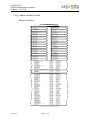
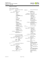
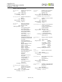
Content
1.
Introduction...........................................................................4
1.1.
1.2.
2.
Product description................................................................5
2.1.
2.2.
3.
Safety information......................................................................... 6
Order information.........................................................................6
System devices.......................................................................8
3.1.
3.2.
3.3.
3.4.
3.5.
3.6.
3.7.
3.8.
3.9.
3.10.
4.
clima DL-110.................................................................................. 8
clima DWM-20 / 21 / 21-rH...........................................................16
clima DWM-01............................................................................. 20
clima DWM-11-rH......................................................................... 22
clima DMS-20.............................................................................24
dialog DRC-10.............................................................................. 27
Connecting cable RJ9...................................................................29
clima DMB-10.............................................................................30
clima A24-10 AC and A24-10DC.....................................................31
clima A24-T................................................................................. 34
Applications..........................................................................37
4.1.
5.
Hardware support.......................................................................37
Creating and configuring the clima DL-110............................39
5.1.
5.2.
5.3.
5.4.
6.
Equip the unit.............................................................................39
Configuration of the device..........................................................39
Configuration of the hardware.....................................................41
Configuration of objects...............................................................76
Bindings.............................................................................158
6.1.
6.2.
6.3.
6.4.
6.5.
6.6.
7.
Occupancy evaluation................................................................158
Temperature regulation.............................................................160
Multiple evaluation....................................................................162
Synchronisation of operating units.............................................164
Master-Slave for room climatic control.......................................166
Thermo automatic...................................................................... 168
Interface description...........................................................169
7.1.
Version 1.02
Explanations of pictogrammes used..............................................4
Use of manual............................................................................... 4
Application................................................................................169
Page 2 / 223
clima DL-110
LON Universal room controller
Order-no.: 331 110
7.2.
8.
spega e.control Plug-ins.....................................................218
8.1.
8.2.
8.3.
8.4.
9.
Installation................................................................................218
Preparing to use the plug-ins.....................................................218
Device and object plug-ins.........................................................219
Service of the device plug-ins.....................................................219
Appendix............................................................................222
9.1.
9.2.
Version 1.02
Objects....................................................................................... 173
Support..................................................................................... 222
Glossary.................................................................................... 222
Page 3 / 223
clima DL-110
LON Universal room controller
Order-no.: 331 110
1. Introduction
Thank you for choosing a spega product. This product has been designed and optimized for
use in room automation. To familiarize yourself with the handling and functionality of the
system, we would ask you to read this manual carefully. It contains information about the
operation, assembly and parameterization of the system.
Please store this manual in a location which is easily accessible to all users!
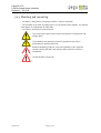
1.1. Explanations of pictogrammes used
This guide uses pictogrammes as warning symbols to ensure the equipment is handled
safely and works properly.
VOLTAGE: indicates immediate danger of harmful electric shock if
disregarded. This could result in severe or fatal injuries to persons.
WARNING: indicates other immediate dangers if disregarded. This could
result in severe or fatal injuries to persons.
CAUTION: indicates a source of danger which could lead to property or
environmental damage if disregarded.
NOTE: indicates recommendations for use which must always be followed
to ensure proper operation. Failure to observe these recommendations,
however, will not result in damage to the equipment.
1.2. Use of manual
Version 1.02
Page 4 / 223
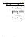
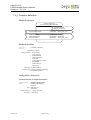
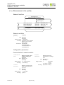
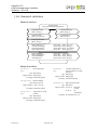
General handling of
the plug-ins
Device templates interfaces
Setting-up and
configuring a device
Applications
Product description
Owners
Planners
Electrical specialists
Systems integrators
Introduction
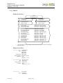
This manual is intended for all groups of persons involved in the planning, installation,
commissioning and maintenance of the system. A overview of which chapter is relevant for
which group of persons is shown below.
clima DL-110
LON Universal room controller
Order-no.: 331 110
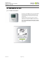
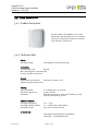
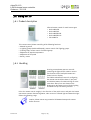
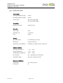
2. Product description
The clima DL-110 compact controller is
designed as a universal room controller. The
various extensions enable you to adapt clima
DL-110 functions to your exact requirements.
It is ideal for controlling static heating and
cooling systems as well as fan coils and
façade ventilation systems.
To make the clima DL-110 even more flexible,
it can be enhanced with various room control
devices, with and without air humidity
measurements,
for
temperature
measurement and adjustment. It is also easy
to connect a multisensor for occupancy detection and room brightness measurement and as
a receiver for IR remote control.
The compact controller is configured using the LNS plug-ins available. We can also consider
adaptations specific to individual customers, if desired.
Version 1.02
Page 5 / 223
clima DL-110
LON Universal room controller
Order-no.: 331 110
2.1. Safety information
Please note the following safety information:
The device function is determined by the application program. Only
programs which have been by released by spega for the device may be
loaded.
The system installer must ensure that the application program and the
related parametrization conform to the wiring and intended application of
the device.
The relevant standards, directives, requirements and regulations of the
respective country must be observed when installing electrical equipment.
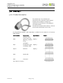
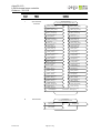
2.2. Order information
Order
number
331 110
clima DL-110,
Universal room controller
934 520
clima DWM-20,
Wall module with temperature sensor, LC display, push buttons for
setpoint and fan speed adjustment, pure white, compatible with room
controller clima DL-110
934 521
clima DWM-21,
Wall module with temperature sensor, LC display, push buttons for
setpoint adjustment, pure white, compatible with room controller clima
DL-110
934 526
clima DWM-21-rH,
Wall module with temperature and humidity sensor, LC display, push
buttons for setpoint adjustment, pure white, compatible with room
controller clima DL-110
930 301
clima DWM-01,
Wall module with temperature sensor, pure white, compatible with room
controller clima DL-110
934 311
clima DWM-11-rH,
Wall module with temperature and humidity sensor, pure white,
compatible with room controller clima DL-110
934 120 W
Version 1.02
Description
clima DMS-20,
Multisensor for suspended ceiling mounting, pure white, compatible with
room controller clima DL-110
Page 6 / 223
clima DL-110
LON Universal room controller
Order-no.: 331 110
Version 1.02
910 112
dialog DRC-10,
Infrared remote control with LC display, compatible with multisensors
lumina MS4, lumina MS4/RC and clima DMS-20
930 001
Connection cable RJ9 (length: 6m)
RJ9 cable for connection wall modules DWM-01 / 11 (-rH), DWM-2x-(rH)
or multisensor DMS-20 to universal controller DL-110
930 002
Connection cable RJ9 (length: 8m)
RJ9 cable for connection wall modules DWM-01 / 11 (-rH), DWM-2x-(rH)
or multisensor DMS-20 to universal controller DL-110
930 003
Connection cable RJ9 (length: 12m)
RJ9 cable for connection wall modules DWM-01 / 11 (-rH), DWM-2x-(rH)
or multisensor DMS-20 to universal controller DL-110
930 004
Connection cable RJ9 (length: 20m)
RJ9 cable for connection wall modules DWM-01 / 11 (-rH), DWM-2x-(rH)
or multisensor DMS-20 to universal controller DL-110
930 005
Connection cable RJ9 (length: 30m)
RJ9 cable for connection wall modules DWM-01 / 11 (-rH), DWM-2x-(rH)
or multisensor DMS-20 to universal controller DL-110
930 110
clima DMB-10,
Mounting box with cover, compatible with room controller clima DL-110
020 325
clima A 24-T,
Noiseless thermoelectric actuator with optical position indicator, with
on/off control, closed when de-energised; matching valve adapters on
request
020 345
clima A 24-10AC,
Noiseless thermoelectric actuator with optical position indicator,
continuous positioning via 0-10V AC, closed when de-energised; matching
valve adapters on request
020 346
clima A 24-10DC,
Noiseless thermoelectric actuator with optical position indicator,
continuous positioning via 0-10V DC, closed when de-energised; matching
valve adapters on request
Page 7 / 223
clima DL-110
LON Universal room controller
Order-no.: 331 110
3. System devices
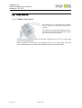
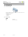
3.1. clima DL-110
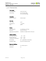
3.1.1 Product description
The clima DL-110 is a universal room controller. It is
suitable for controlling static heating/cooling
systems (like radiators, heated/chilled ceilings,
chilled beams) and fan coil systems. Here the usage
of 2-pipes, 3-pipes and 4-pipes-system are
supported.
Additionally wall modules with temperature sensor,
humidity sensor and push buttons for setpoint and
fanspeed adjustment can be connected as well as a
multisensor for presence detection, for
measurement of ambient brightness in rooms and
as receiver for the infrared remote control with LC
display dialog DRC-10.
An LNS plug-in for comfortable configuration is
available.
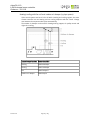
Available inputs and outputs
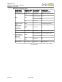
The inputs and outputs listed in the following table can be freely configured.
Type
Number
Usage
Analog input 0-10V
1
e.g. Air quality sensor
Analog input für NTC 10kOhm
2
Temperature sensor
Digital input for floating contacts
4
e.g. Window contact, dew point sensor,
hotel card switch
Analog output 0-10V
2
e.g. Valve or damper actuator, fan
Digital output 24 VDC
2
e.g. Valve actuator (2-point and 3-point)
Fan output 230 VAC (max. 3-stage)
1
Fan
Switching output 230VAC
1
e.g. Heater battery, contactor (relay) for
central-off
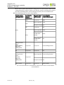
Supported heating/cooling systems
The heating/cooling systems listed below are supported by clima DL-110. Thereby the
required actuators can be freely assigned to the available outputs.
• Heating with radiator
Version 1.02
Page 8 / 223
clima DL-110
LON Universal room controller
Order-no.: 331 110
• Heating with radiator, air quality control with VAV
• Heating with radiator, cooling and air quality control combined with VAV
• Cooling with chilled ceiling
• Cooling with chilled ceiling, air quality control with VAV
• Cooling with chilled ceiling, heating and air quality control combined with VAV
• Cooling with chilled ceiling, heating with radiator
• Cooling with chilled ceiling, heating with radiator, air quality control with VAV
• Heating and cooling with combined heated/chilled ceiling (2-pipe system)
• Heating and cooling with combined heated/chilled ceiling (2-pipe system), air quality
control with VAV
• Heating and cooling with combined heated/chilled ceiling (4-pipe system, 4 valves)
• Heating and cooling with combined heated/chilled ceiling (4-pipe system, 4 valves), air
quality control with VAV
• Heating and cooling with combined heated/chilled ceiling (4-pipe system, 3 valves)
• Heating and cooling with combined heated/chilled ceiling (4-pipe system, 3 valves), air
quality control with VAV
• Heating and cooling with combined heated/chilled ceiling (4-pipe system, 6-way valve)
• Heating and cooling with combined heated/chilled ceiling (4-pipe system, 6-way valve),
air quality control with VAV
• Cooling with fan coil
• Cooling with fan coil, air quality control with VAV
• Cooling with fan coil, heating and air quality control combined with VAV
• Cooling with fan coil with outdoor air damper (incl. air quality control)
• Cooling with fan coil, heating with radiator
• Cooling with fan coil, heating with radiator, air quality control with VAV
• Cooling with fan coil with outdoor air damper (incl. air quality control), heating with
radiator
• Heating with fan coil
• Heating with fan coil, air quality control with VAV
• Heating with fan coil, cooling and air quality control combined with VAV
• Heating with fan coil with outdoor air damper (incl. air quality control)
• Heating and cooling with fan coil (2-pipe system)
• Heating and cooling with fan coil (2-pipe system), air quality control with VAV
• Heating and cooling with fan coil with outdoor air damper (2-pipe system), incl. air
quality control
• Heating and cooling with fan coil (4-pipe system)
• Heating and cooling with fan coil (4-pipe system), air quality control with VAV
• Heating and cooling with fan coil with outdoor air damper (4-pipe system), incl. air
quality control
For supporting not listed heating/cooling systems please contact our support. Please find
the contact information at the end of this data sheet.
Version 1.02
Page 9 / 223
clima DL-110
LON Universal room controller
Order-no.: 331 110
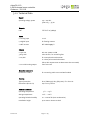
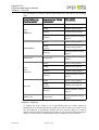
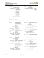
3.1.2 Technical Data
Supply
operating voltage, power
230 - 240 VAC,
50/60 Hz, 3 - 34 VA
Network
LON
FTT TP/FT-10 (78kbps)
Inputs
1 x analog input
0-10 V
4 x digital input
for floating contacts
2 x NTC sensors
NTC 10KOhm@25°C
Outputs
1 x 230 VAC
8A, max. power 1.8 KW
3 X 230 VAC
max. 2A each, for controlling fans
2 x 24 VDC
for 2 two point thermal actuator
or 1 three point motorized actuator.
(All 24 VDC outputs must not draw more then max 0.8A!)
2 x 0-10 VDC analog output
max. 2mA each
Extension connectors
Connectors A and B
for connecting multi sensor and wall module
Housing
Type of protection
IP 20 (EN 60529), IK05 (EN 50102), Fire: Class V2
Dimensions (W x H x D)
140 x 102 x 51.6 mm
Ambient conditions
Operating temperature
Version 1.02
5°C ... +45°C
Storage temperature
-10°C ... +60°C
Operating Relative humidity
20 ... 80% of RH (w/o condensation)
Installation height
up to 2000 m above sea level
Page 10 / 223
clima DL-110
LON Universal room controller
Order-no.: 331 110
CE-Conformity
2004/108/EC Electromagnetic Compatibility
2006/95/EC Low voltage directive
Version 1.02
Page 11 / 223
clima DL-110
LON Universal room controller
Order-no.: 331 110
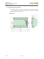
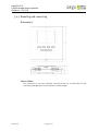
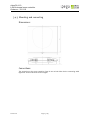
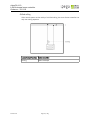
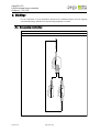
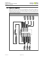
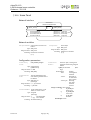
3.1.3 Mounting and connecting
The assembly of clima DL-100 is able in a switch cupboard or directly with 2 side flaps,
e. g. , in the false ceiling. There is also the possibility to mount the device in the seperat
available assembly box "clima DMB-10".
Dimensions:
Version 1.02
Page 12 / 223
clima DL-110
LON Universal room controller
Order-no.: 331 110
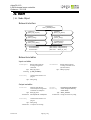
24V
010 V
GND
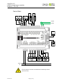
Window contact
υ
CO 2
Dewp oint sen sor
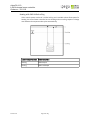
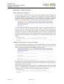
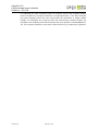
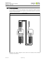
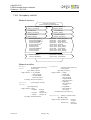
Connections:
LON A
LON B
Wall
module
RJ9
RJ9
Multisensor
N
Level Level Level
1
2
3
24V
GND
GND
010V
24V
M
24V DC
24 V DC
230 V
N
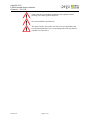
Electrical devices must be assembled and installed by trained
personnel only.
Version 1.02
Page 13 / 223
clima DL-110
LON Universal room controller
Order-no.: 331 110
Please observe local standards, guidelines and regulations when
planning and installing electrical devices.
Do not exceed device specifications.
The system installer has to take care that the correct application and
the associated parameters are corresponding with the wiring and the
intended use of the device.
Version 1.02
Page 14 / 223
clima DL-110
LON Universal room controller
Order-no.: 331 110
3.1.4 EMC-compliant cabling within the building
As a rule, all legal standards and directives governing the design of cabling must be
observed. By adhering to the following information regarding cabling installed in buildings,
devices may be protected against electromagnetic interference, particularly in the case of
high EMC loads.
Laying of different cables
Motor cables, power supply cables and general feed cables for sub-distribution boards and
system distributors are cables which may interfere with bus cables, extra-low-voltage cables
and general signal lines and control cables. Consequently, both these categories of cable
must always be laid separately. In cases where cable junctions cannot be avoided, the
cables should ideally be laid at right angles to each other.
Selecting a bus cable
When selecting the LON bus cable the installation instructions for LON networks - the
Echelon Wiring Guidelines - must be observed at all times. In addition, the use of twisted
pairs for the cable types specified must be ensured. When using J-Y(St)Y or comparable
cable types, we recommend the use of the green EIB cable.
Shielded cables have better EMC properties than non-shielded cables. A proper earthing
system is a basic requirement for an EMC-compliant installation . It must be ensured that no
equipotential bonding current can flow across the shields of data or bus cables.
Power supply lines
24V power supply lines must be designed such that the voltage drop on the line is no more
than 2 volts. The maximum power consumption of all connected devices should be taken as
a basis for this. Please note that both current-carrying conductors must be taken into
account when calculating the line resistance. These supply lines must not be routed in the
same cable together with mains cables.
Signal lines
Stranded pairs of cables must be used for connecting digital and analog sensors. These
signal lines must not be routed in the same cable together with mains cables.
Version 1.02
Page 15 / 223
clima DL-110
LON Universal room controller
Order-no.: 331 110
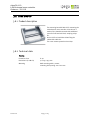
3.2. clima DWM-20 / 21 / 21-rH
3.2.1 Product description
The devices clima DWM-20/21/21-rH are wall modules
with temperature and optional humidity sensor for
connecting directly to the universal room controller
clima DL-110.
The wall modules have push-buttons for setpoint
adjustment, fan speed (only DWM-20) and presence.
The LC display shows the room temperature, setpoint
offset, fan speed (only DWM-20), occupancy state and
window state.
Version 1.02
Page 16 / 223
clima DL-110
LON Universal room controller
Order-no.: 331 110
3.2.2 Technical data
Supply
Operating voltage
Low voltage via communication port
Connections
Communication port
RJ9 jack
Max. cable length for connection 30m
to room controller clima DL-110
Display
LCD
LCD with backlight
Displaying
Room temperature, setpoint offset, fan speed (only DWM20), occupancy state and window state
Operation
Push-buttons for
Setpoint adjustment, fan speed (only clima DWM-20),
presence
Sensors
Temperature measurement
NTC sensor 10 kOhm / 25°C
Relative humidity measurement (only clima DWM-21-rH)
Housing
Type of protection
IP 20 (EN 60529), Fire: Class V0
Dimensions (W x H x D)
91 x 84 x 24 mm
Installation
Wall mounting with 2 screws (max. diameter 3,5 mm),
mounting hole spacing: 60 mm
Ambient conditions
Version 1.02
Operating temperature
0°C ... +40°C
Operating relative humidity
20 ... 80% RH (w/o condensation)
Installation height
up to 2000 m above sea level
Page 17 / 223
clima DL-110
LON Universal room controller
Order-no.: 331 110
CE-Conformity
2004/108/EC Electromagnetic Compatibility
2006/95/EC Low voltage directive
Version 1.02
Page 18 / 223
clima DL-110
LON Universal room controller
Order-no.: 331 110
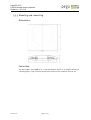
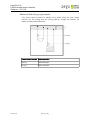
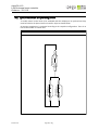
3.2.3 Mounting and connecting
Dimensions:
Connections:
The connection to the room controller clima DL-110 will do on both sides via the
connecting cable RJ9 which can be ordered in various lengths.
Version 1.02
Page 19 / 223
clima DL-110
LON Universal room controller
Order-no.: 331 110
3.3. clima DWM-01
3.3.1 Product description
The wall module clima DWM-01 is a room
temperature sensor in an elegant housing for
connecting directly to the universal room
controller clima DL-110.
3.3.2 Technical data
Connections
For temperature sensor
2-pin terminal connection
Max. cable length for connection 30m with 2x0.8mm
to room controller clima DL-110
Sensors
Temperature measurement
NTC sensor 10 kOhm / 25°C
Housing
Type of protection
IP 20 (EN 60529), Fire: Class V0
Dimensions (W x H x D)
91 x 84 x 24 mm
Installation
Wall mounting with 2 screws (max. diameter 3,5 mm),
mounting hole spacing: 60 mm
Ambient conditions
Operating temperature
0°C ... +40°C
Operating relative humidity
20 ... 80% RH (w/o condensation)
Installation height
up to 2000 m above sea level
CE-Conformity
2004/108/EC Electromagnetic Compatibility
2006/95/EC Low voltage directive
Version 1.02
Page 20 / 223
clima DL-110
LON Universal room controller
Order-no.: 331 110
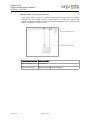
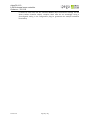
3.3.3 Mounting and connecting
Dimensions:
Connection:
The wall module clima DWM-01 is a room temperature sensor in an elegant housing for
connecting with a 2-pin connector directly to the universal room controller clima DL-110.
Version 1.02
Page 21 / 223
clima DL-110
LON Universal room controller
Order-no.: 331 110
3.4. clima DWM-11-rH
3.4.1 Product description
The wall module clima DWM-11-rH is a room
temperature and humidity sensor in an elegant
housing for connecting directly to the universal
room controller clima DL-110.
3.4.2 Technical data
Supply
Operating voltage
Low voltage via communication port
Connections
Communication port
RJ9 jack
Max. cable length for connection 30m
to room controller clima DL-110
Sensors
Temperature measurement
NTC sensor 10 kOhm / 25°C
Relative humidity measurement
Housing
Type of protection
Dimensions (W x H x D)
Installation
Ambient conditions
Operating temperature
Operating relative humidity
Installation height
IP 20 (EN 60529), Fire: Class V0
91 x 84 x 24 mm
Wall mounting with 2 screws (max. diameter 3,5 mm),
mounting hole spacing: 60 mm
0°C ... +40°C
20 ... 80% RH (w/o condensation)
up to 2000 m above sea level
CE-Conformity
2004/108/EC Electromagnetic Compatibility
2006/95/EC Low voltage directive
Version 1.02
Page 22 / 223
clima DL-110
LON Universal room controller
Order-no.: 331 110
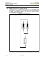
3.4.3 Mounting and connecting
Dimensions:
Connections:
The connection to the room controller clima DL-110 on both sides via the connecting cable
RJ9 which can be ordered in various lengths.
Version 1.02
Page 23 / 223
clima DL-110
LON Universal room controller
Order-no.: 331 110
3.5. clima DMS-20
3.5.1 Product description
The multi sensor is a combination of occupancy
sensor, light sensor and infrared remote control
receiver.
The multi sensor transmits the telegrams of the
infrared remote control dialog DRC-10 directly to
the room controller clima DL-110.
The light sensor provides the basis of automatic lighting functions, such as constant light
control or daylight switching.
With the optional infrared remote control dialog DRC-10 you can control lights, blinds and
scenes. Additionally you can adjust the temperature setpoint and the fan speed.
Version 1.02
Page 24 / 223
clima DL-110
LON Universal room controller
Order-no.: 331 110
3.5.2 Technical data
Power supply
Operating voltage
Low voltage via communication port
Connections
Communication port
1 x 9RJ jack
Presence detection
Detection range
4m Ø at 2.5m installation height
Housing
Type of protection
IP 40
dimensions
43 x 56 mm (Ø x H)
Installation dimensions
35 x 45 mm (Ø x H)
Ambient conditions
Operating temperature
0 °C ... +40°C
CE-Conformity
2004/108/EC Electromagnetic Compatibility
2006/95/EC Low voltage directive
Version 1.02
Page 25 / 223
clima DL-110
LON Universal room controller
Order-no.: 331 110
3.5.3 Mounting and connecting
Dimensions:
Connections:
The connection to the room controller clima DL-110 on both sides via the connecting cable
RJ9 which can be ordered in various lengths.
Version 1.02
Page 26 / 223
clima DL-110
LON Universal room controller
Order-no.: 331 110
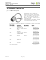
3.6. dialog DRC-10
3.6.1 Product description
Infrared remote control for multi sensor types
•
•
•
•
•
lumina MS4-EB
lumina MS4-AP
lumina MS4/RC-EB
lumina MS4/RC-AP
clima DMS-20
This remote control allows controlling of the following functions:
•
•
•
•
•
•
Manual log on/off
4 Lighting groups (switched/dimmed), master control of all lighting groups
4 Blind groups, master control of all blind groups
Adjustment of setpoint temperature
Adjustment of fan speed
Recall 3 scenes
3.6.2 Handling
Pressing a menu button opens a menu for
controlling the lights, blinds, HVAC or scenes.
The functions of the small push buttons are
shown in the LC display.
The hidden maintenance menu for configuring
the remote control will be shown, if you press
and hold the buttons for HVAC and log on at the
same time. After 4 lines are shown on the
display press the buttons log on, blinds, lighting
and HVAC one by one within 3 seconds.
Point the remote control roughly in the direction of the multi sensor and push the button
you want to operate. Extreme brightness, other sources of infrared light and obstacles might
reduce the operating range.
Caution: Please remove any protective lid between battery and contacts
before first use!
Version 1.02
Page 27 / 223
clima DL-110
LON Universal room controller
Order-no.: 331 110
3.6.3 Technical data
Supply
operating voltage
2 x 1,5V AAA Type battery, LR03 Alkaline (included)
Housing
Type of protection
IP30
Colour
Pure white
Dimensions (H x W x D)
145 x 61 x 20 mm
Ambient conditions
Operating temperature
-5°C ... +45°C
Relative humidity
Max 93% (w/o condensation)
Installation height
up to 2000 m above sea level
CE-Conformity
2004/108/EC Electromagnetic Compatibility
2006/95/EC Low voltage directive
Version 1.02
Page 28 / 223
clima DL-110
LON Universal room controller
Order-no.: 331 110
3.7. Connecting cable RJ9
3.7.1 Product description
The cable is designed in various lengths for easy and user-friendly connection of the
following devices to the clima DL-110.
• clima DWM-20 / 21 / 21-rH
• clima DWM-01 / 11-rH
• clima DMS-20
3.7.2 Technical data
Connector
Version 1.02
RJ9
on both ends
Length
6m, 8m, 12m, 20m, 30m
Page 29 / 223
clima DL-110
LON Universal room controller
Order-no.: 331 110
3.8. clima DMB-10
3.8.1 Product description
The mounting box with DIN rail for mounting the
LON universal room controller clima DL-110 is
made of zinc plated sheet steel with additional
space for fuse terminal block, coupling relays
etc.
Strain reliefs on both sides allow fixing the
cables with cable ties.
The cover ensures protection class IP40
3.8.2 Technical data
Housing
Version 1.02
Protection class
IP 40
Dimensions (H x W x D)
70 x 275 x 255 mm
Mounting
Wall mounting with 4 screws,
mounting hole spacing: 220 x 200 mm
Page 30 / 223
clima DL-110
LON Universal room controller
Order-no.: 331 110
3.9. clima A24-10 AC and A24-10DC
3.9.1 Product description
The actuator A24-10xx is a noiseless and
maintenance-free continuous electro-thermal
actuator that is suitable for connection to clima
RCM CC, clima RO-CC, clima AA4-10V, clima
AA8-10V or clima FCB-10V. The control signal is
a 0-10V analog signal.
The drive has an optical level indicator, so that at
any time the valve position can be read.
By using different adapters (sold separately) is suitable to use the actuator for all common
types of valves:
Order number:
Valve Brand:
Specification:
VA80
Heimeier, Herb,
Onda, Oeven-trop
M30x1,5
(M30x1,5), Schlösser
ab 93
VA50
Honeywell,
Brauckmann, Reich, M30x1,5
Landis&Gyr, MNG
VA50H
Böhnisch
VA78
Danfoss RA
VA26
Giacomoni
M30x1,5
Other adapters on request
Version 1.02
Page 31 / 223
Picture:
clima DL-110
LON Universal room controller
Order-no.: 331 110
3.9.2 Technical data
Power supply
Operating voltage (020 345)
24 VAC
Operating voltage (020 346)
24 VDC
Current input
typ. 80 mA (1920 mW)
max.250 mA (6000mW)
Connections
Actuator connection
Cable end open
Drive data
Travel range
3 mm
Operating time
< 3 minutes
Force
90 Nm
Housing
Type of protection
IP 20 (DIN 40050 / IEC 144)
Dimensions
48 x 43 mm (B x D)
Type/location of installation
Installation of radiator valves or heat cycle
Ambient conditions
Operating temperature
-5°C ... +45°C
Storage temperature
-25°C ... +55°C
Transportation temperature
-25°C ... +70°C
Rel. humidity
5% .. 93% (without condensation)
Installation height
up to 2000 m above sea level
Standards / guidelines
Version 1.02
Device safety
acc. to EN 50 090-2-2
Certification
CE
Page 32 / 223
clima DL-110
LON Universal room controller
Order-no.: 331 110
3.9.3 Mounting and connecting
• The device is designed for mounting on radiator - valves or manifolds.
• The assembly of the valve by simply place it on the optional valve adapter. The optional
valve adapter is screwed onto the valve body.
• The cable is connected via screw terminals.
The circuits of the inputs must meet the requirements for safety extra-low
voltage (SELV)
The installation and assembly of electrical equipment may only be
performed by a qualified electrician.
Relevant standards, guidelines, rules and regulations of the respective
country must be observed in the planning and construction of electric
installations.
The specification must be met.
Version 1.02
Page 33 / 223
clima DL-110
LON Universal room controller
Order-no.: 331 110
3.10. clima A24-T
3.10.1 Product description
The actuator A24-T is a noiseless and
maintenance-free continuous electro-thermal
actuator that is suitable for example for
connection to clima FCB-24 or clima AA8 and
clima AA4 actuators.
The drive has an optical level indicator, so that at
any time the valve position can be read.
By using different adapters (sold separately) is suitable for the actuator for all common
types of valves:
Order number:
Valve brand:
Specification:
VA80
Heimeier, Herb,
Onda, Oeven-trop
M30x1,5
(M30x1,5), Schlösser
ab 93
VA50
Honeywell,
Brauckmann, Reich, M30x1,5
Landis&Gyr, MNG
VA50H
Böhnisch
VA78
Danfoss RA
VA26
Giacomoni
M30x1,5
Other adapters on request
Version 1.02
Page 34 / 223
Picture:
clima DL-110
LON Universal room controller
Order-no.: 331 110
3.10.2 Technical data
Power supply
Operating voltage
24V AC / DC ±10%
Current input
typ. 80mA (1920mW)
max. 250mA (6000mW)
Connections
Actuator connection
Cable end open
Drive Data
Travel range
3 mm
Operating time
< 3 minutes
Force
90 Nm
Housing
Type of protection
IP 20 (DIN 40050 / IEC 144)
Dimensions
48 x 43 mm (B x D)
Type/location of installation
Installation of radiator valves or heat cycle
Ambient conditions
Operating temperature
-5°C ... +45°C
Storage temperature
-25°C ... +55°C
Transportation temperature
-25°C ... +70°C
Rel. humidity
5% .. 93% (without condensation)
Installation height
up to 2000 m above sea level
Standards / guidelines
Version 1.02
Device safety
acc. to EN 50 090-2-2
Certification
CE
Page 35 / 223
clima DL-110
LON Universal room controller
Order-no.: 331 110
3.10.3 Mounting and connecting
• The device is designed for mounting on radiator - valves or manifolds.
• The assembly of the valve by simply place it on the optional valve adapter. The optional
valve adapter is screwed onto the valve body.
• The cable is connected via screw terminals.
The circuits of the inputs must meet the requirements for safety extra-low
voltage (SELV)
The installation and assembly of electrical equipment may only be
performed by a qualified electrician.
Relevant standards, guidelines, rules and regulations of the respective
country must be observed in the planning and construction of electric
installations.
The specification must be met.
Version 1.02
Page 36 / 223
clima DL-110
LON Universal room controller
Order-no.: 331 110
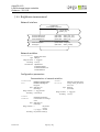
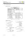
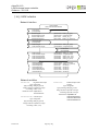
4. Applications
Using the clima DL-110 application you can capture and control a wide selection of
various sensors and actuators. The software is divided into logical objects in accordance
with LonMark™ Interoperability Guidelines.
Application
Objects
1 x LightSensor
1 x OccupancySensor
2 x TempSensor
SC331110EC_02
1 x AirQualitySensor
1 x RelHumSensor
1 x CommandModule
4 x BinaryInput
8 x Switch
1 x ScenePanel
1 x OccupancyCtrl
1 x DewPointCalc
1 x SpaceComfortCtrl
1 x ThermoCtrl
8 x HvacActuator
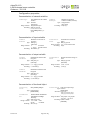
Application data
You can select the desired application in the spega device template manager. All the
required application files, resource files and plug-ins for the relevant project will be
loaded.
Application
SC331110EC_02
Software files
SC331110EC_02.APB
SC331110EC_02.NXE
SC331110EC_02.XIF
SC331110EC_02.XFB
Resource Files
econtrol2 Resource files version 1.09 required
Plug-ins
Device plug-in clima DL-110, object plug-ins
The software complies with LonMark™ Interoperability Guidelines.
When using LNS-based integration tools we recommend the use of the
resource files listed.
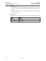
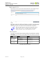
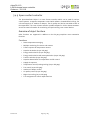
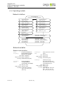
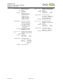
4.1. Hardware support
The clima DL-110 room controller can be used for a variety of applications. The device
features digital and analogue inputs and outputs, a fan stage output for controlling
corresponding actuators using up to three stages, as well as a 230V switching output.
The various connection options are summarised in the table below:
Type
Version 1.02
Quantity
Use
0-10V analogue input
1
e.g. air quality sensor
Analogue input for NTC
10kOhm
2
Temperature sensor
Digital input for floating
contacts
4
e.g. window contact, dew point sensor, hotel key
card switch
Page 37 / 223
clima DL-110
LON Universal room controller
Order-no.: 331 110
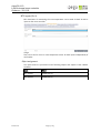
230VAC switching output
1
e.g. heating register, contactor (relay) for Master Off
230 VAC fan stage output
(max. 3 stages)
1
e.g. for activating a 3-stage fan
24 VDC digital output
2
e.g. valve actuator (2-point and 3-point)
0-10V analogue output
2
e.g. valve actuator, damper actuator, fan
In addition, the device offers the option of connecting external modules using 2 RJ9 sockets
and incorporating them into the room control system. The following modules are available
for this purpose:
Module
Description
clima DWM-20
Wall module with temperature sensor, LC display and push buttons
for adjusting the target temperature and fan stage
clima DWM-21
Wall module with temperature sensor, LC display and push buttons
for adjusting the target temperature
clima DWM-21-rH
Wall module with temperature and air humidity sensor, LC display
and push buttons for adjusting the target temperature
clima DWM-11-rH
Wall module with temperature and air humidity sensor
clima DMS-20
Multisensor for slot installation
The modules are connected using a cable assembly with RJ9 connectors on both sides.
The following module combinations are supported:
Connection A
Connection B
Description
Multisensor
Wall module
All functions of the multisensor and wall module can be
used
not used
Wall module
The wall module can be fully utilised
Multisensor
not used
The multisensor can be fully utilised
Multisensor
The multisensor on connection A can be fully utilised
Only the occupancy sensor can be evaluated by the
multisensor on connection B. This occupancy sensor is
linked via an "OR" function to the occupancy sensor of
the multisensor on connection A. An existing IR manual
remote control can only be evaluated via the
multisensor on connection A.
Multisensor
Version 1.02
Page 38 / 223
clima DL-110
LON Universal room controller
Order-no.: 331 110
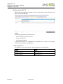
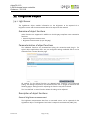
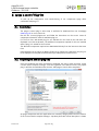
5. Creating and configuring the clima DL-110
5.1. Equip the unit
To use a clima DL-110 device for your project, you must first install the e.control plug-in
setup program either from the CD or from the Internet. The setup program contains the
application files, LNS plug-ins and the user manual. More information on how to install and
use the plug-ins is given in the chapter entitled "spega e.control plug-ins".
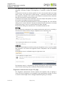
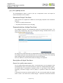
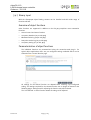
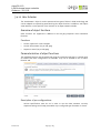
First you must create a device template in your LNS project. For this you have the spega
e.control device template manager, which can be run as a plug-in on your project. The
clima DL-110 device can be found in the category "Universal room controllers". Here you can
choose from a list of all available device templates. Select the desired template and accept it
for your project. You can then set up the device in the usual way using the corresponding
device template.
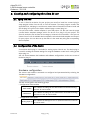
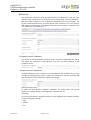
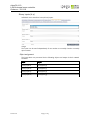
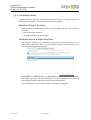
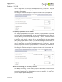
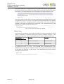
5.2. Configuration of the device
A convenient device plug-in is available for starting up the clima DL-110. The device plug-in
is used for making the relevant settings for using the hardware as well as for calling up the
object plug-ins.
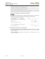
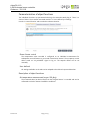
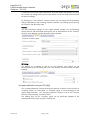
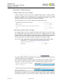
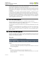
You can choose between the hardware and software configurations on the start screen of
the device plug-in.
Hardware configuration
The sensors and actuators connected are configured and parameterised by selecting the
"Hardware configuration".
The tabs are assigned to the following groups:
• Configuration of the modules
Wall module
This is where all settings for the wall module connected to the RJ9
terminal "B" can be made.
Multisensor
This is where all settings for the multisensors connected via the RJ9
terminals "A" and "B" can be made.
• Configuration of the inputs
Analog input (U)
Version 1.02
This is where the settings for the "U" input terminal on the clima DL110 can be made.
Page 39 / 223
clima DL-110
LON Universal room controller
Order-no.: 331 110
NTC inputs (S1, 2)
Binary inputs
(I1-4)
This is where the settings for input terminals "S1" and "S2" can be
made.
This is where the settings for input terminals "I1" to "I4" can be made.
• Configuration of the outputs
Digital output
(K1)
This is where the settings for a 230V actuator connected to output
terminal "K1" can be made.
This is where multiple-step fans or 2-point drives with a 230V power
Digital outputs
supply can be parameterised, which are connected to output
(F1-F3)
terminals "F1" to "F3".
Digital outputs This is where 24V actuators with 2-point or 3-point control can be
(Y1, 2)
parameterised, which are connected to output terminals "Y1" to "Y2".
Analog outputs This is where analog actuators with a 0-10V or a 2-10V signal can be
(Y3, 4)
parameterised, which are connected to output terminals "Y3" to "Y4".
The setting options available on the individual tabs are described in detail under
"Configuration of the hardware".
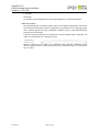
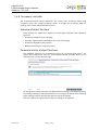
Software configuration
You can switch directly to the relevant object plug-ins by selecting "Software configuration".
This initiates a full start-up of the system.
The individual objects are grouped according to their basic functionality:
• Sensors
This is where all objects used for capturing sensors are listed. Objects with an assigned
input which, according to the hardware configuration, is not in use, are hidden.
• Controllers
The control objects available can be called up and parameterised.
• Actuators
This is where all objects used for activating the outputs are listed. Objects with an
assigned output which, according to the hardware configuration, is not in use, are
hidden.
The setting options available on the individual tabs are described in detail under
"Configuration of the software".
Version 1.02
Page 40 / 223
clima DL-110
LON Universal room controller
Order-no.: 331 110
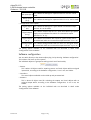
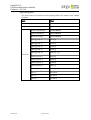
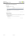
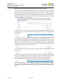
5.3. Configuration of the hardware
The configuration of the hardware is divided into the available modules, the sensors and the
actuators.
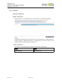
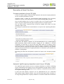
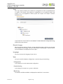
5.3.1 Modules
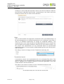
Wall module
The wall modules available are listed in the table below. The system automatically
detects what type of wall module is connected.
Module
Description
clima DWM-20
Wall module with temperature sensor, LC display and push buttons
for adjusting the temperature setpoint and fan stage
clima DWM-21
Wall module with temperature sensor, LC display and push buttons
for adjusting the temperature setpoint
clima DWM-21-rH
Wall module with temperature and relative humidity sensor, LC
display and push buttons for adjusting the temperature setpoint
clima DWM-11-rH
Wall module with temperature and relative humidity sensor
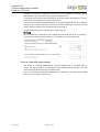
The configuration options on the "Wall module" tab, as described below, apply only to
wall modules with an LCD display.
Version 1.02
Page 41 / 223
clima DL-110
LON Universal room controller
Order-no.: 331 110
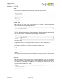
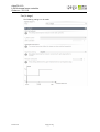
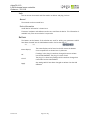
States
Selecting the individual states activates their respective display screens.
Display value
With regard to the value shown on the display, it is possible to choose between the
space temperature and setpoint temperature.
Display format
Once the display value has been chosen the display format can also be adjusted. The
unit of measurement, resolution and setpoint display can be defined.
Dimension unit:
Temperature values can be displayed either in Celsius (°C) or in Fahrenheit (°F).
Resolution:
The following resolutions can be used to display the temperature:
• 0.1
• 0.5
• 1.0 (decimal places are not shown)
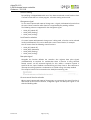
Setpoint:
If the setpoint has been specified for the value shown, then you must also specify for the
setpoint display whether relative or absolute values are to be shown.
Operation
With wall modules featuring push buttons, setpoint adjustment control and manual fan
control are possible. Activating the setpoint adjustment also activates the setpoint bar.
The fan levels are displayed independently of any manual fan control options; this is
activated or deactivated under "States".
Version 1.02
Page 42 / 223
clima DL-110
LON Universal room controller
Order-no.: 331 110
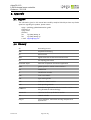
Object assignment:
The input values are processed via the following objects and output via their network
variables:
Input
Object
Space temperature
CommandModule
Relative humidity
RelHumSensor*
Setpoint adjustment
CommandModule
Manual fan control
CommandModule
Presence signalisation CommandModule
* if no relative humidity sensor is parameterised on the U input port
The states and values displayed are received via network variables on the following
objects:
Version 1.02
Display
Object
Space temperature
CommandModule
Setpoint
CommandModule
States
CommandModule
Occupancy
CommandModule
Fan levels
CommandModule
Page 43 / 223
clima DL-110
LON Universal room controller
Order-no.: 331 110
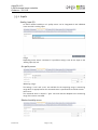
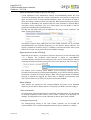
Multisensor
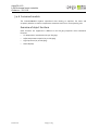
Any multisensor connected can be parameterised on the "Multisensor" tab. If a room
controller with 2 multisensors is being used, the settings apply to both multisensors.
With the second multisensor only occupancy is detected by the room controller. The
signals from both multisensors are linked by the room controller via an "OR" function
and output as a status signal. The signals from the IR remote control are received on the
first multisensor alone (channel A).
Occupancy sensor (indicator)
The LED for the motion detection indication can be activated or deactivated. The setting
only affects the multisensor's LED indication. This does not affect operation of the
occupancy sensor.
Occupancy sensor (detection)
Occupancy detection by the multisensor can be adapted to the conditions of the room.
The type of heating/cooling system is taken into account here and the sensitivity and
type of evaluation of the multisensor adjusted accordingly.
Heating/cooling system:
To ensure the best possible occupancy evaluation, the system takes into account
whether the heating/cooling is operating with or without a fan coil.
Sensitivity:
The level of sensitivity for occupancy detection can be adapted to the ambient conditions
using the following 4 settings:
• high
• middle
• low
Version 1.02
Page 44 / 223
clima DL-110
LON Universal room controller
Order-no.: 331 110
• very low
Evaluation:
It is possible to switch between fast and slow evaluation for occupancy detection.
Infrared receiver
Using the dialog DRC-10 infrared remote control, local setpoint adjustments, manual fan
level selection and manual presence signalisation are possible. Up to 4 lighting groups
and 4 sunblind groups can also be operated. In addition, up to 3 room utilisation types
(scenes) can be controlled.
A specific infrared channel can be specified for infrared remote control evaluation. All
codes are received if the "all" setting is chosen.
Where 2 multisensors are used on an individual room controller, evaluation of the
infrared remote control is performed solely on the multisensor which is connected to
the "A" socket.
Version 1.02
Page 45 / 223
clima DL-110
LON Universal room controller
Order-no.: 331 110
Object assignment
The input values are processed via the following objects and output via the network
variables:
Input
Object
Occupancy detection
OccupancySensor
Brightness
LightSensor
IR receiver
Version 1.02
Presence signalisation
CommandModule
Setpoint adjustment
CommandModule
Manual fan control
CommandModule
Lighting group "1"
Switch [0]
Lighting group "2"
Switch [1]
Lighting group "3"
Switch [2]
Lighting group "4"
Switch [3]
Lighting group "all"
Switch [0] - [3]
Sunblind group "1"
Switch [4]
Sunblind group "2"
Switch [5]
Sunblind group "3"
Switch [6]
Sunblind group "4"
Switch [7]
Sunblind group "all"
Switch [4] - [7]
Scene "1"
ScenePanel
Scene "2"
ScenePanel
Scene "3"
ScenePanel
Page 46 / 223
clima DL-110
LON Universal room controller
Order-no.: 331 110
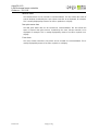
5.3.2 Inputs
Analog input (U)
An active relative humidity or air quality sensor can be integrated via the individual
room controller's analog input.
Usage:
Depending on the sensor connected, it is possible to assign a use for the input on the
"Analog input (U)" tab.
Air quality sensor
Measuring range:
The settings "0-10V" and "2-10V" are available for the measuring range. A measuring
range which is appropriate for the connected sensor's specifications should be chosen.
Value at xV:
The measured value is output in "ppm" unit and must be adapted to the measuring
range of the sensor connected.
Relative humidity sensor
Version 1.02
Page 47 / 223
clima DL-110
LON Universal room controller
Order-no.: 331 110
Measuring range:
The settings "0-10V" and "2-10V" are available for the measuring range. A measuring
range which is appropriate for the connected sensor's specifications should be chosen.
Value at xV:
The measured value is output in "%" unit and must be adapted to the measuring range
of the sensor connected.
Object assignment
The input values are processed via the following objects and output via their network
variables:
Version 1.02
Input
Object
Air quality
AirQualSensor
Relative humidity
RelHumSensor
Page 48 / 223
clima DL-110
LON Universal room controller
Order-no.: 331 110
NTC inputs (S1, 2)
NTC thermistors for measuring the room temperature can be used via both S1 and S2
inputs on the room controller.
Usage:
They can be set for use as a room temperature sensor for both inputs independently of
one another.
Object assignment
The input values are processed via the following objects and output via the network
variables:
Version 1.02
Input
Object
NTC input S1
TempSensor [0]
NTC input S2
TempSensor [1]
Page 49 / 223
clima DL-110
LON Universal room controller
Order-no.: 331 110
Binary inputs (I1-4)
Individual room controllers have 4 binary inputs.
Usage:
The inputs can be used independently of one another as normally closed or normally
open contacts.
Object assignment
The input values are processed via the following objects and output via their network
variables:
Version 1.02
Input
Object
Binary input I1
BinaryInput [0]
Binary input I2
BinaryInput [1]
Binary input I3
BinaryInput [2]
Binary input I4
BinaryInput [3]
Page 50 / 223
clima DL-110
LON Universal room controller
Order-no.: 331 110
5.3.3 Outputs
Choice of the use
Digital output (K1)
Digital output K1 on the individual room controller offers a 230V switching output.
Usage:
The digital switching output can be used for the 2-point activation of a valve, damper or
electrical heater. A detailed description on configuring it for this use is given in the
chapter entitled "Parameterisation of output use".
Object assignment
The output is controlled using the network variable of the related object:
Version 1.02
Output
Object
Digital output K1
HvacActuator [0]
Page 51 / 223
clima DL-110
LON Universal room controller
Order-no.: 331 110
Digital outputs (F1 - 3)
Digital outputs F1 to F3 can be used to activate 230V (2A) actuators and fans.
Usage:
The individual digital outputs have a number of applications. It should be noted that not
all applications can be set on each channel. A detailed description on configurations for
individual uses is given in the chapter entitled "Parameterisation of output use".
NOTE: In terms of the usage "Fan (2-stage)" the following output is
required for activation; for the usage "Fan (3-stage)" both the following
outputs are required. The relevant outputs are automatically blocked in
the plug-in and no further application can be set.
Object assignment
The outputs are controlled using the network variable of the related object, regardless
of the usage. If the usage requires several digital outputs, these outputs are controlled
by one object:
Usage
Outputs
Objects
Digital output F1
HvacActuator [1]
Digital output F2
HvacActuator [2]
Digital output F3
HvacActuator [3]
Digital output F1
Valve, damper or
electrical heater (2- Digital output F2
point control)
Digital output F3
HvacActuator [1]
Fan (on/off)
Fan (2-stage)
Fan (3-stage)
HvacActuator [2]
HvacActuator [3]
Digital outputs F1* and F2
HvacActuator [1]
Digital outputs F2* and F3
HvacActuator [2]
Digital outputs F1*, F2 and F3
HvacActuator [1]
* the usage is set on this channel
Version 1.02
Page 52 / 223
clima DL-110
LON Universal room controller
Order-no.: 331 110
Digital outputs (Y1, Y2)
Digital outputs Y1 and Y2 can be used to activate valves with a control voltage of 24V DC.
Usage:
Both digital outputs have different applications. It should be noted that not all
applications can be set on each channel. A detailed description on configurations for
individual uses is given in the chapter entitled "Parameterisation of output use".
NOTE: Both digital outputs are required for the application "Valve or
damper (3-point control)". The Y2 digital output is automatically
blocked in the plug-in and no further application can be set.
Object assignment
The outputs are controlled using the network variable of the related object, regardless
of the usage. If the usage requires several digital outputs, these outputs are controlled
by one object:
Usage
Outputs
Objects
Valve, damper or Digital output Y1
electrical heater (2Digital output Y2
point control)
Valve or damper (3Digital outputs Y1* and Y2
point control)
HvacActuator [4]
HvacActuator [5]
HvacActuator [4]
* the usage is set on this channel
Version 1.02
Page 53 / 223
clima DL-110
LON Universal room controller
Order-no.: 331 110
Analog outputs (Y3, Y4)
With analog switching outputs Y3 and Y4 valves and fans with a control voltage of 0-10V
and 2-10V can be controlled.
Usage:
Both analog outputs have a number of uses.
• Valve or damper (continuous control)
• 3-way or 6-way valve
• Fan (continuous control)
A detailed description on configurations for individual uses is given in the chapter
entitled "Parameterisation of output use".
Object assignment
The outputs are controlled using the network variable of the related object:
Version 1.02
Output
Object
Analog output Y3
HvacActuator [6]
Analog output Y4
HvacActuator [7]
Page 54 / 223
clima DL-110
LON Universal room controller
Order-no.: 331 110
Parameterization of the output using
Fan (on/off)
The following settings can be made:
Switching performance
Minimum running time:
Stipulating a minimum running time ensures the fan remains switched on for at least
the period of time specified.
Version 1.02
Page 55 / 223
clima DL-110
LON Universal room controller
Order-no.: 331 110
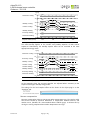
Fan (2-stage)
The following settings can be made:
Version 1.02
Page 56 / 223
clima DL-110
LON Universal room controller
Order-no.: 331 110
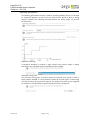
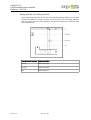
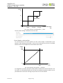
Start-up behavior
The start-up behavior determines how the fan responds when it is switched on. It is only
executed if the required activation setting is lower than the parameterised start-up
setting.
Start-up level:
By parameterising the start-up setting you can stipulate which minimum setting is
activated when the fan is switched on. With a lower fan setting, therefore, the fan is
activated at the start-up setting for the parameterised start-up time.
Start-up duration:
Once the start-up time has elapsed the fan is activated at the lower activation setting
requested. The parameterised minimum running time does not affect the validity of the
start-up time.
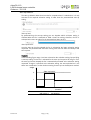
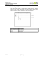
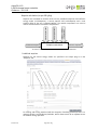
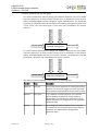
Example:
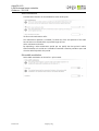
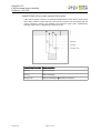
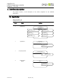
In the following figure stage 1 has been selected as the activation setting. By specifying
a start-up setting of 2 the fan is activated for the start-up time period for stage 2. Once
the start-up time has elapsed the fan is automatically activated at the activation setting
requested. If stage 2 is specified as the activation setting, the start-up behaviour is not
taken into consideration, as the minimum setting for start-up has already been reached.
Stage
2
Start-up level 2
1
t0
Event
Version 1.02
Switch on
with stage 1
Page 57 / 223
t0 +start-up
duration
End of startup duration
Time
clima DL-110
LON Universal room controller
Order-no.: 331 110
Switching performance
The switching performance function is used for specifying whether the fan is to be used
for sequential operation, as well as for the minimum time period in which a stage
remains activated. The switching threshold between the setting stages can also be
parameterised.
Sequential switching:
If sequential switching is selected, a stage change across several stages is always
executed in such a way that each intermediate stage is actuated.
Minimum running time:
The minimum running time is used to specify the minimum time period in which a
stage remains activated. It is only possible to switch to the next higher or lower stage
once the minimum running time has expired. The validity of the start-up time triggered
on activation is not affected by the parameterised minimum running time.
Version 1.02
Page 58 / 223
clima DL-110
LON Universal room controller
Order-no.: 331 110
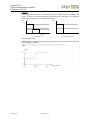
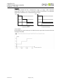
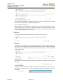
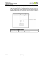
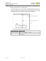
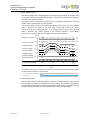
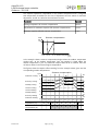
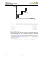
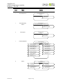
Example:
In the figure below the fan is switched from stage 2. With sequential switching, fan
stage 1 is run for the minimum running time when the fan is shut down. If no sequential
switching is selected the fan is switched off directly.
Stage
Stufe
2
2
1
1
t0
t 0 +minimum
runtime
Time
Sequential switching
t0
Time
No sequential switching
Control output value:
By specifying the control output value you can determine the input value from which the
next fan stage is activated.
Version 1.02
Page 59 / 223
clima DL-110
LON Universal room controller
Order-no.: 331 110
Fan (3-stage)
The following settings can be made:
Start-up behavior
The start-up behavior determines how the fan responds when it is switched on. It is only
executed if the required activation setting is lower than the parameterised start-up
setting.
Start-up level:
By parameterising the start-up setting you can stipulate which minimum setting is
activated when the fan is switched on. With a lower fan setting, therefore, the fan is
activated at the start-up setting for the parameterised start-up time.
Version 1.02
Page 60 / 223
clima DL-110
LON Universal room controller
Order-no.: 331 110
Start-up duration:
Once the start-up duration has elapsed the fan is activated at the lower activation
setting requested. The parameterised minimum running time does not affect the validity
of the start-up duration.
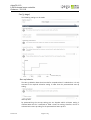
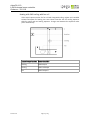
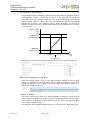
Example:
In the following figure stage 2 has been selected as the activation setting. By specifying
a start-up setting of 3 the fan is activated for the start-up time period for stage 3. Once
the start-up time has elapsed the fan is automatically activated at the activation setting
requested. If stage 3 is specified as the activation setting, the start-up behaviour is not
taken into consideration, as the minimum setting for start-up has already been reached.
Stage
3
Start-up level 3
2
1
t0
Event
Version 1.02
Switch on
with stage 2
Page 61 / 223
t0 +start-up
duration
End of startup duration
Time
clima DL-110
LON Universal room controller
Order-no.: 331 110
Switching performance
The switching performance function is used for specifying whether the fan is to be used
for sequential operation, as well as for the minimum time period in which a setting
remains activated. The switching threshold between the setting stages can also be
parameterised.
Sequential switching:
If sequential switching is selected, a stage change across several stages is always
executed in such a way that each intermediate stage is actuated.
Minimum running time:
The minimum running time is used to specify the minimum time period in which a
stage remains activated. It is only possible to switch to the next higher or lower stage
once the minimum running time has expired. The validity of the start-up time triggered
on activation is not affected by the parameterised minimum running time.
Version 1.02
Page 62 / 223
clima DL-110
LON Universal room controller
Order-no.: 331 110
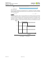
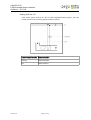
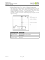
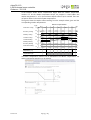
Example:
In the figure below the fan is switched from stage 3 to stage 1. With sequential
switching, fan stage 2 is run for the minimum running time specified. If no sequential
switching is selected the fan is switched directly to stage 1.
Stage
Stage
3
3
2
2
1
1
t 0 +minimum
runtime
Sequential switching
t0
Time
t0
Time
No sequential switching
Control value:
By specifying the control value you can determine the input value from which the next
fan stage is activated.
Version 1.02
Page 63 / 223
clima DL-110
LON Universal room controller
Order-no.: 331 110
Fan (continuous control)
The following settings can be made:
Start-up behavior
The start-up behavior determines the minimum setting with which the fan is activated
and for how long this output remains active. The start-up behavior is only executed if
the required activation value is lower than the parameterised start-up setting.
Start-up control value:
By parameterising the start-up control value you can specify the minimum percentage
value at which the fan is activated. Requests for lower settings are temporarily
overridden.
Start-up duration:
Once the start-up duration has elapsed the fan is activated at the lower setting
requested.
Version 1.02
Page 64 / 223
clima DL-110
LON Universal room controller
Order-no.: 331 110
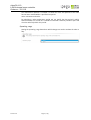
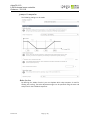
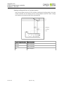
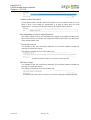
Example:
In the figure shown below a requested setting of 15% was given. However, the fan is
activated for the set start-up time at a parameterised start-up setting of 80%. Once the
start-up time has elapsed the start-up setting override is cancelled and the fan is
activated at the requested setting of 15%.
Value
%
100
Start-up
value 80
15
t0
Event
Switch on
with 15%
t0 +start-up
duration
End of start up duration
Time
Operating range:
By setting the operating range you can specify which voltages are used to activate the
valve.
Version 1.02
Page 65 / 223
clima DL-110
LON Universal room controller
Order-no.: 331 110
Valve or damper (continuous control)
The following settings can be made:
Mode of action
By defining the mode of action, you can stipulate the behavior of a valve or flap on
reaching the minimum level of the defined operating range on the output.
Valve maintenance
A maintenance function can be activated for valves at this point.
Perform valve maintenance after:
Version 1.02
Page 66 / 223
clima DL-110
LON Universal room controller
Order-no.: 331 110
The maintenance operation is initiated if at least one of the end positions of the valve
has not been reached within a specified time period.
Valve maintenance duration:
By stipulating a valve maintenance period you can specify the time period in which
valve maintenance is carried out. It should be noted that it must be possible to open and
close the valve fully within this period.
Operating range
Setting the operating range determines which voltages are used to activate the valve or
flap.
Version 1.02
Page 67 / 223
clima DL-110
LON Universal room controller
Order-no.: 331 110
Valve, damper or electric heater (2-point control)
The following settings can be made:
Mode of action
The "Mode of action" function allows you to choose whether the connected actuator is
open or closed when de-energised.
Version 1.02
Page 68 / 223
clima DL-110
LON Universal room controller
Order-no.: 331 110
Valve maintenance
A maintenance function can be activated for valves at this point.
Perform valve maintenance after:
The maintenance operation is initiated if at least one of the end positions of the valve
has not been not reached within a specified length of time.
Valve maintenance duration:
By stipulating a valve maintenance period you can specify the time period in which
valve maintenance is carried out. It should be noted that it must be possible to open and
close the valve fully within this period.
Pulse width modulation
Pulse width modulation can be set for 2-point control.
Version 1.02
Page 69 / 223
clima DL-110
LON Universal room controller
Order-no.: 331 110
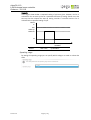
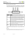
With this a constant control output value can be used to influence a thermoelectric
actuator, for example, in such a way that the averaged flow rate is proportional to the
control output value. The figure shows an example of pulse width modulation for a
control output value of 60%
Value
%
100
60%*t C
0
60%*t C
tC
60%*tC
2*t C
60%*t C
3*tC
60%*tC
4*tC
5*tC Time
tC – Cycle time
Cycle time:
This is where the duration of a pulse width modulation cycle is set. Pulse width
modulation is deactivated if the time is set to 0 seconds.
Limitation:
In the case of low and high control output values, switching cycles which follow in very
quick succession may occur. To prevent this a symmetrical limit can be set.
In the case of the above setting the following applies:
For control output values below 5% the output remains switched off. With control
output values of 95% and above (100% - limit value), on the other hand, the output
remains permanently switched on. In both cases pulse width modulation is not active.
Version 1.02
Page 70 / 223
clima DL-110
LON Universal room controller
Order-no.: 331 110
Valve or damper (3-point control)
With 3-point control two outputs are used to activate a drive. One output is used to open
and the other to close the actuator. The following settings can be made for 3-point
control:
Mode of action
Using the "Mode of action" function you can choose which output is activated to open
the actuator and which to close it. If the "Normal" setting is chosen the first output is
used for opening, and with the "Inverted" setting the second output is used for opening.
Valve maintenance
A maintenance function can be activated for valves at this point.
Version 1.02
Page 71 / 223
clima DL-110
LON Universal room controller
Order-no.: 331 110
Perform valve maintenance after:
The maintenance operation is initiated if at least one of the end positions of the valve
has not been reached within a specified length of time.
Valve maintenance duration:
By stipulating a valve maintenance period you can specify the time period in which
valve maintenance is carried out. It should be noted that it must be possible to open and
close the valve fully within this period. For this reason the valve maintenance period
must be longer than twice the travel time.
Drive time
The drive time between both end positions should be set in this section.
Calibration
If the drive is controlled using only relative travel movements over a prolonged period of
time, with no direct triggering of one of the end positions, this may result in positioning
inaccuracies. To prevent this, calibration may be performed after a certain number of
relative movements.
Calibrate after:
The number of relative movements after which calibration is required can be preset at
this point.
Reference position:
During calibration the drive is moved into one of the two end positions and then moves
back into its initial position. You can select whether the valve is opened or closed for
calibration.
Version 1.02
Page 72 / 223
clima DL-110
LON Universal room controller
Order-no.: 331 110
3-way or 6-way valve
The following settings can be made:
Mode of action
By defining the “Mode of action” you can stipulate which valve sequence is used for
heating and cooling. The valve adjustment angles can be specified using the start and
end points for the individual sequences.
Version 1.02
Page 73 / 223
clima DL-110
LON Universal room controller
Order-no.: 331 110
Valve maintenance
A maintenance function can be activated for valves at this point.
Perform valve maintenance after:
The maintenance operation is initiated if at least one of the end positions of the valve is
not reached within a specified length of time.
Valve maintenance duration:
By stipulating a valve maintenance period you can specify the time period in which
valve maintenance is carried out. When fixing the time period it should be noted that
the valve must run both sequences fully in succession for maintenance purposes.
Operating range
Setting the operating range determines which voltage is used to activate the valve.
Version 1.02
Page 74 / 223
clima DL-110
LON Universal room controller
Order-no.: 331 110
Parameterization of the maintenance function
Maintenance
The maintenance function can be used to protect the connected valves against seizing. A
time window can be parameterised on the "Maintenance" tab that applies to all outputs.
Time window for valve maintenance:
To activate the time window test, the current time stamp must be transmitted via the
nviTimeSet of the node object. The time stamp must be updated at regular intervals for
synchronisation purposes.
Movements into the maintenance positions are only performed during the specified
time period. If no time test is to be carried out, the time window should be extended
over the whole day. This is done by entering the same time for the start and end. With
this setting maintenance can be carried out at any time of day. The valves are
maintained successively.
NOTE: You should specify in the configuration of the relevant output
whether a valve is to be maintained.
Version 1.02
Page 75 / 223
clima DL-110
LON Universal room controller
Order-no.: 331 110
5.4. Configuration of objects
5.4.1 Light Sensor
The LightSensor object enables information on the brightness to be captured via a
brightness sensor and the measurement data to be output into the network.
Overview of object functions
Other functions are supported in addition to the VDI 3813-compliant room automation
functions:
• General brightness measurement
• Brightness measurement (as per VDI 3813)
Parameterisation of object functions
The individual functions are parameterised using the convenient web plug-in. For
typical object applications there are pre-configured settings available which can be
selected on the e.control function page:
All settings for the desired function are adopted when choosing a pre-configured
setting. The settings required for the selected function can no longer be altered on the
following pages. Settings used for adjusting the function may still be altered.
The "User defined" e.control function allows all settings to be adjusted.
Description of object functions
General brightness measurement
The brightness measurement data from a connected sensor can be captured via the
LightSensor object. The brightness level value is output via nvoLsLuxLevel (SNVT_lux).
Version 1.02
Page 76 / 223
clima DL-110
LON Universal room controller
Order-no.: 331 110
The output value is sent as standard if there is any change in the brightness. By
specifying a minimum change in the brightness it is possible to reduce the network
load.
A transmission interval can also be specified. For this, the time after which the output
value is resent - even if there are no value changes - is specified. Transmission intervals
are required, for example, if the receiver is set to detect a transmitter failure. Note here
that cyclic transmission increases the bus load.
A minimum time interval may be defined for successive output data packets, to ensure
the receiver has enough time to process the packets.
In order to enable the described parameters to be freely configured, the "User defined"
setting on the "e.control function" tab may be selected. Several parameters are already
preset via the plug-in once an e.control function has been selected.
The parameter settings are selected on the "Transmission behaviour" tab.
Nv timing:
You can choose the parameters for the settings mentioned as well as for re-sending, a
minimum time interval and the change in brightness on the "Nv timing" tab:
Calibration:
Calibration should always be used for starting up a brightness sensor, to ensure reliable
data evaluation. This ensures the brightness sensor is adjusted to suit its installation
conditions.
The brightness sensor is calibrated using the "Light sensor" tab.
The brightness sensor is calibrated by entering the brightness value measured by the
reference value measuring device. Calibration should be performed in daylight.
Brightness measurement (as per VDI 3813)
The "Brightness measurement" function captures the brightness level of lighting in
rooms. The level of brightness is transmitted via the output network variable. It can be
re-used for constant light control or daylight-dependent lighting, for example.
Version 1.02
Page 77 / 223
clima DL-110
LON Universal room controller
Order-no.: 331 110
It is set to "Brightness measurement" by selecting it as a room brightness sensor on the
"e.control function" tab.
Version 1.02
Page 78 / 223
clima DL-110
LON Universal room controller
Order-no.: 331 110
5.4.2 Occupancy sensor
Occupancy detection using the OccupancySensor object allows an occupancy sensor to be
picked up and information on its status to be sent into the network.
Overview of object functions
Other functions are supported in addition to the VDI 3813-compliant room automation
functions:
• General occupancy detection
• Occupancy detection (as per VDI 3813)
Parameterisation of object functions
The individual functions are parameterised using the convenient web plug-in. For
typical object applications there are preconfigured settings available which can be
selected on the e.control function page:
All settings for the desired function are adopted when choosing a preconfigured setting.
The settings required for the selected function can no longer be altered on the following
pages. Settings used for adjusting the function may still be altered.
The "User-defined" e.control function allows all settings to be adjusted.
Version 1.02
Page 79 / 223
clima DL-110
LON Universal room controller
Order-no.: 331 110
Description of object functions
General occupancy detection
An occupancy sensor can be picked up via the OccupancySensor object. The occupancy
signal is output via nvoOsOccSensor (SNVT_occupancy).
The output values for room occupancy can be adjusted. The values which can be
selected are shown in the table below:
Output value for:
Network variable type
Room occupied
Room unoccupied
Occupied (OC_OCCUPIED)
SNVT_occupancy
Unoccupied (OC_UNOCCUPIED)
Comfort extension (bypass) (OC_BYBASS)
Standby (OC_STANDBY)
A holding time can be set for the "Room occupied" output value. This allows the
presence signal to be maintained for the specified time period.
The output value is transmitted as standard if there is a change in the sensor state. A
transmission interval can also be specified. For this, the time after which the output
value is resent - even if there is no change in state - is specified. Transmission intervals
are required, for example, if several sensors or control points on the receiver are to be
evaluated, or if the receiver is set to detect a transmitter failure. Note here that cyclic
transmission increases the network load.
By selecting "User-defined" as an e.control function, all parameter settings can be
individually adjusted to suit the required ambient conditions. The settings are made
using the "General" and "Nv timing" tabs.
Version 1.02
Page 80 / 223
clima DL-110
LON Universal room controller
Order-no.: 331 110
General:
The afore-mentioned settings for the occupancy command output value and the holding
time for the occupancy signal can be parameterised on the "General" tab, if the "Userdefined" e.control function has been selected.
Nv timing:
You can set the parameters for re-sending on the "Nv timing" tab, if the "User-defined"
e.control function has been selected:
Occupancy detection (as per VDI 3813)
The "Occupancy detection" function detects the presence of persons in the room using
an occupancy sensor. The "Occupied" and "Unoccupied" output values are transmitted
via the output network variable. The "Occupancy detection" function is set on the
"e.control function" tab by selecting "Occupancy sensor".
The holding time for the "Occupied" signal can be adjusted on the "General" tab.
Version 1.02
Page 81 / 223
clima DL-110
LON Universal room controller
Order-no.: 331 110
5.4.3 Temperature sensor
The TempSensor object is used to pick up a temperature sensor and output its measurement
data into the network.
Overview of object functions
Other functions are supported in addition to the VDI 3813-compliant room automation
functions.
• General temperature measurement
• Air temperature measurement (as per VDI 3813)
Parameterisation of object functions
The individual functions are parameterised using the convenient web plug-in. For
typical object applications there are preconfigured settings available which can be
selected on the e.control function page:
All settings for the desired function are adopted when choosing a pre-configured
setting. The settings required for the selected function can no longer be altered on the
following pages. Settings used for adjusting the function may still be altered.
The "User defined" e.control function allows all settings to be adjusted.
Version 1.02
Page 82 / 223
clima DL-110
LON Universal room controller
Order-no.: 331 110
Description of object functions
General temperature measurement
The temperature values from a connected sensor can be captured via the TempSensor
object. The temperature value is output via nvoTsTemp (SNVT_temp_p).
The temperature sensor can be used for individual measurements, e.g. for an office
with a temperature sensor, or for generating an average temperature, e.g. for an open
plan office with several temperature sensors, which are each connected to a
TempSensor object.
The output value is sent as standard if there is any change in temperature. By specifying
a minimum change in the temperature it is possible to reduce the network load.
A transmission interval can also be specified. For this, the time after which the output
value is resent - even if there are no value changes - is specified. Transmission intervals
are required if several sensors or control points on the receiver are to be evaluated, or if
the receiver is set to detect a transmitter failure. Note here that cyclic transmission
increases the bus load.
A minimum time interval may be defined for successive output data packets, to ensure
the receiver has enough time to process the packets.
However, if the measured value is to be used for generating an average temperature,
then it must be sent just once only within the message transmission interval of the room
climate controller. For this purpose new measurements are only transmitted within the
parametrisable transmission interval. This then prevents multiple weighting of the
sensor during mean-value generation.
In order to enable the described parameters to be freely configured, the "User defined"
setting on the "e.control function" tab may be selected. Several parameters are already
preset via the plug-in once an e.control function has been selected.
Version 1.02
Page 83 / 223
clima DL-110
LON Universal room controller
Order-no.: 331 110
The parameter settings are selected on the "Temperature measurement" tab.
Temperature measuring:
You can choose the parameters for the application as well as for re-sending, a
minimum time interval and the change in brightness on the "Temperature
measurement" tab:
Calibration:
Irrespective of how the temperature sensor is used, it should always be calibrated. This
ensures the temperature sensor is adjusted to suit widely varying installation
conditions. The temperature sensor is calibrated using the "Temperature sensor" tab.
The temperature sensor is calibrated by entering the temperature value measured by
the reference value measuring device.
Air temperature measurement (as per VDI 3813)
The "Air temperature measurement" function captures the room temperature or the
intake and exhaust air temperature in heating and cooling systems. The temperature
value is transmitted via the output network variable. The The "Air temperature
measurement" function is set on the "e.control function" tab by selecting it as a room
temperature sensor, intake air temperature sensor or exhaust temperature sensor.
• Room temperature sensor: For single offices the temperature can be taken as an
individual measurement, and for open plan offices with several measuring points the
individual TempSensor objects on a room climate controller can be grouped to calculate
an average temperature. The settings required for the transmission interval are already
pre-configured via the plug-in. The temperature difference for re-sending can be
adjusted.
• Intake air temperature sensor: In air assist systems the intake air can be used for
heating and cooling support. You can specify whether the intake air temperature is used
for this purpose. Its use and the transmission interval are preset via the plug-in. The
Version 1.02
Page 84 / 223
clima DL-110
LON Universal room controller
Order-no.: 331 110
temperature difference for re-sending can be adjusted to suit the prevailing ambient
conditions.
• Exhaust air temperature sensor: To protect a fan coil from overheating its exhaust
temperature can be measured. The room climate controller is able to reduce the fan
coil's capacity or its heating register if the exhaust temperature is too high. Its use and
the transmission interval are preset via the plug-in. The temperature difference for resending can be adjusted to suit the prevailing ambient conditions.
Version 1.02
Page 85 / 223
clima DL-110
LON Universal room controller
Order-no.: 331 110
5.4.4 Air quality sensor
The AirQualitySensor object is used to pick up a temperature sensor and output its
measurement data into the network.
Overview of object functions
Other functions are supported in addition to the VDI 3813-compliant room automation
functions.
• General air quality measurement
• Air quality measurement (as per VDI 3813)
Parameterisation of object functions
The individual functions are parameterised using the convenient web plug-in. For
typical object applications there are preconfigured settings available which can be
selected on the e.control function page:
All settings for the desired function are adopted when choosing a preconfigured setting.
The settings required for the selected function can no longer be altered on the following
pages. Settings used for adjusting the function may still be altered.
The "User-defined" e.control function allows all settings to be adjusted.
Description of object functions
General air quality measurement
The air quality measurement values from a connected sensor can be captured via the
AirQualitySensor object. The measured value is output via nvoAqAirQuality (SNVT_ppm).
The output value is transmitted as standard if there is any change in the value. By
specifying a minimum change in the air quality it is possible to reduce the network
load.
A transmission interval can also be specified. For this, the time after which the output
value is resent - even if there are no value changes - is specified. Transmission intervals
Version 1.02
Page 86 / 223
clima DL-110
LON Universal room controller
Order-no.: 331 110
are required, for example, if the receiver is set to detect a transmitter failure. Note here
that cyclic transmission increases the network load.
A minimum time interval may be defined for successive output data packets, to ensure
the receiver has enough time to process the packets.
In order to enable the described parameters to be freely configured, the "User-defined"
setting on the "e.control function" tab may be selected. Selecting an e.control function
means several parameters are already preset via the plug-in.
The parameter settings are selected on the "Nv timing" tab.
Nv timing:
You can choose the parameters for the settings mentioned as well as for re-sending, a
minimum time interval and the change in air quality on the "Nv timing" tab:
Air quality measurement (as per VDI 3813)
The "Air quality measurement" function detects the air quality in rooms. The air quality
measured is transmitted via the output network variable. It can be used for air quality
control, for example.
It is set to "Air quality measurement" by selecting it as an air quality sensor on the
"e.control function" tab.
Version 1.02
Page 87 / 223
clima DL-110
LON Universal room controller
Order-no.: 331 110
5.4.5 Relative humidity sensor
The RelHumSensor object is used to pick up an air humidity sensor and output its
measurement data into the network.
Overview of object functions
The object supports the following functions:
• General measurement of relative air humidity
• Room air humidity measurement
Parameterisation of object functions
The individual functions are parameterised using the convenient web plug-in. For
typical object applications there are preconfigured settings available which can be
selected on the e.control function page:
All settings for the desired function are adopted when choosing a preconfigured setting.
The settings required for the selected function can no longer be altered on the following
pages. Settings used for adjusting the function may still be altered.
The "User-defined" e.control function allows all settings to be adjusted.
Description of object functions
General measurement of relative air humidity
The RelHumSensor object can be used to collect the measured values from a connected
analogue sensor to measure the relative air humidity. The air humidity value is output
via nvoRhRelHumidity (SNVT_lev_percent).
The output value is transmitted as standard if there is any change in the measured
values. By specifying a minimum change in air humidity it is possible to reduce the
network load.
A transmission interval can also be specified. For this, the time after which the output
value is re-sent - even if there are no value changes - is specified. Transmission
Version 1.02
Page 88 / 223
clima DL-110
LON Universal room controller
Order-no.: 331 110
intervals are required, for example, if the receiver is set to detect a transmitter failure.
Note here that cyclic transmission increases the network load.
A minimum time interval may be defined for successive output data packets, to ensure
the receiver has enough time to process the packets.
In order to enable the described parameters to be freely configured, the "User-defined"
setting on the "e.control function" tab may be selected. Selecting an e.control function
means several parameters are already preset via the plug-in.
The parameter settings are selected on the "Nv timing" tab.
Nv timing
You can choose the parameters for the settings mentioned as well as for re-sending, a
minimum time interval and the change in air humidity on the "Nv timing" tab:
Room air humidity measurement
The "Room air humidity measurement" function captures the air humidity level in
rooms. The data evaluation is transmitted via the output network variable. It can be
used to calculate the dew point of a chilled ceiling.
It is set to "Relative air humidity measurement" by selecting it as a room air humidity
sensor on the "e.control function" tab.
Version 1.02
Page 89 / 223
clima DL-110
LON Universal room controller
Order-no.: 331 110
5.4.6 Command module
The CommandModule captures operational data relating to setpoints, fan levels and
occupancy switches, as well as temperature measurements from a room operating unit.
Overview of object functions
Other functions are supported in addition to the VDI 3813-compliant room automation
functions.
Version 1.02
•
Air temperature measurement (as per VDI 3813)
•
Adjust temperature setpoint (as per VDI 3813)
•
Signal presence (as per VDI 3813)
•
Status displays
Page 90 / 223
clima DL-110
LON Universal room controller
Order-no.: 331 110
Parameterisation of object functions
The individual functions are parameterised using the convenient web plug-in. There is a
choice of either "Pace comfort command module" or "User-defined" pre-settings.
Use the "e.control function" tab to make the relevant selection.
Room climate control
The temperature value recorded is configured as an individual measurement for
subsequent use and features a 30-second transmission interval. The occupancy control
device sends an "OC_OCCUPIED" signal to log on. The setpoint offsets can be set
manually.
User-defined
All settings available on the tabs can be adapted to the desired response behaviour.
Description of object functions
Air temperature measurement (as per VDI 3813)
The measured value (at device level) from the assigned sensor is recorded and can be
calibrated to suit the relevant installation conditions.
Version 1.02
Page 91 / 223
clima DL-110
LON Universal room controller
Order-no.: 331 110
Calibration
Calibration is used to adapt the temperature sensor to the device installation conditions.
You will find the calibration function under "Commissioning" in the "View" menu item.
The device must be online in order to select calibration.
Usage
You can choose whether the temperature measurement value ( nvoCmSpaceTemp) is to
be used subsequently as an individual measurement or for calculating a mean value. If
used as an individual measurement, all changes are forwarded. However, if the
measured value is to be used to produce an average temperature, then it must be sent
just once within the message transmission interval of the room climate controller. For
this purpose new measurements are only transmitted within the parametrisable
transmission interval. This then prevents multiple weighting of the sensor during meanvalue calculation.
This setting is chosen in the plug-in on the "Temperature measuring" tab.
Transmission interval
A transmission interval can be parameterised for the nvoCmSpaceTemp value. If the
measured value is to be used subsequently to generate an average temperature, a value
which is adjusted to the reception interval for mean-value generation in the room
climate controller must be entered here.
This setting is also chosen in the plug-in on the "Temperature measuring" tab:
The nvoCmSpaceTemp value is sent after the set time period
Version 1.02
Page 92 / 223
clima DL-110
LON Universal room controller
Order-no.: 331 110
Adjust temperature setpoint (as per VDI 3813)
A local adjustment of the temperature setpoint (nvoCmSetptOffset) allows the room
climate to be adapted to the user's comfort requirements. It is possible to configure the
upper and lower limits of the permitted adjustment range. The sequence of steps in
which the setting is made should also be specified. When operating using the buttons,
the setpoint is adjusted by one sequence step each time the button is pressed. With a
continuous control component, such as a rotary wheel, the step width is used for
grading and rounding the transmitted values.
The step size and range setting can be adjusted in the plug-in on the "Operation" tab
under "Setpoint shift settings":
The effective setpoint offset fedback by the room climate controller can be recorded
(nviCmSetptOffset) and displayed (depending on the device's display options). The
display is enabled in the device plug-in. In addition, synchronisation with other control
stations in the room can be performed via the feedback message.
Signal presence (as per VDI 3813)
Depending on the device, it is possible to signal the presence of a room manually using
1 or 2 buttons. The occupancy status detected is output on nvoCmManOcc.
"OC_UNOCCUPIED" is always sent for leaving the room. You can choose which occupancy
command should be sent when entering the room on the "Operation" tab in the plug-in.
The effective room occupancy status fedback by the occupancy controller can be
recorded (nviCmOccupancy) and displayed (depending on the device's display options).
The display is enabled in the device plug-in. When using a toggle button the feedback
message is required for toggling the actual state. In addition, synchronisation with
other control stations in the room can be performed via the feedback.
Status displays
Other statuses are captured via the Command Module and these can be displayed
depending on the device's display options. The display is enabled in the device plug-in.
Room temperature
The temperature value to be displayed is received via nviCmSpaceTemp. This also allows
an average temperature value from the room climate controller to be displayed, for
example. The temperature can only be indicated on devices which have a display.
Heating/cooling activity
The heating/cooling activity of the room climate controller can be received via
nviCmUnitStatus. This is usually displayed by means of LEDs or symbols on a display.
Version 1.02
Page 93 / 223
clima DL-110
LON Universal room controller
Order-no.: 331 110
Window status
The window status can be received via nviCmUnitStatus. This also allows the status of
several windows recorded by the room climate controller to be displayed, for example.
This is usually displayed by means of an LED or symbols on a display.
Dew point status data
The dew point status data can be received via nviCmUnitStatus. This also allows the
status of several dew point sensors recorded by the room climate controller to be
displayed, for example. This is usually displayed by means of an LED or symbols on a
display.
Frost alarm
The room climate controller's frost alarm can be received via nviCmUnitStatus. This is
usually displayed by means of an LED or symbols on a display.
Version 1.02
Page 94 / 223
clima DL-110
LON Universal room controller
Order-no.: 331 110
5.4.7 Binary input
With the BinaryInput object floating contacts can be installed and their wide range of
functions utilised.
Overview of object functions
Other functions are supported in addition to the VDI 3813-compliant room automation
functions.
•
General control and sensor function
•
Occupancy detection (as per VDI 3813)
•
Window monitoring (as per VDI 3813)
•
Dew point monitoring (as per VDI 3813)
•
Occupancy setting (as per VDI 3813)
Parameterisation of object functions
The individual functions are parameterised using the convenient web plug-in. For
typical object applications there are pre-configured settings available which can be
selected on the e.control function page:
All settings for the desired function are adopted when choosing a pre-configured
setting. The settings required for the selected function can no longer be altered on the
following pages. Settings used for adjusting the function may still be altered.
The "User defined" e.control function allows all settings to be adjusted.
Version 1.02
Page 95 / 223
clima DL-110
LON Universal room controller
Order-no.: 331 110
Description of object functions
General control and sensor function
Various types of controls and sensors which deliver a binary signal can be captured via
the Binary Input object. The contact states are output via nvoBiValue. The following
types of network variable for the output variable are available for the various control
and sensor functions:
• SNVT_switch:
e.g. for window contacts, dew point sensors or light controls
• SNVT_occupancy: e.g. for hotel key card switches or occupancy sensors
• SNVT_hvac_mode: e.g. for switching between heating and cooling (change-over
signal)
The output values for the steady position and working position of the sensor are
determined on the basis of the type of network variable selected.
The table below shows the values that can be preset/selected:
Network variable type
Function
Standard
SNVT_switch
Output value for:
Steady position
Working position
Switch off
Switch on
Switch on (100.0 1)
User-defined
Switch off (0.0 0)
Invalid (0.0 -1)
Occupancy sensor
Unoccupied
Occupied
Occupied (OC_OCCUPIED)
SNVT_occupancy
Unoccupied (OC_UNOCCUPIED)
User-defined
Comfort extension (bypass) (OC_BYBASS)
Standby (OC_STANDBY)
Invalid (OC_NUL)
Automatic (HVAC_AUTO)
SNVT_hvac_mode
User-defined
Heating (HVAC_HEAT)
Cooling (HVAC_COOL)
Building protection (HVAC_NUL)
A holding time can be set for the output value in the working position. In the case of
occupancy detection, for example, this allows the presence signal to be maintained for
the specified time period.
The output value is transmitted as standard if there is a change in the sensor state. A
transmission interval can also be specified. Here the time period for re-sending is
adjusted accordingly. Transmission intervals are required if several sensors or control
points on the receiver are to be evaluated, or if the receiver is set to detect a transmitter
failure. Note here that cyclic transmission increases the bus load.
Version 1.02
Page 96 / 223
clima DL-110
LON Universal room controller
Order-no.: 331 110
A minimum time interval may be defined for successive output data packets, to ensure
the receiver has enough time to process the packets. To do this check the box and set
the time accordingly.
By selecting the "User defined" e.control function you can adjust all the parameter
settings individually to the prevailing ambient conditions. The settings are made using
the "General" and "Nv timing" tabs.
General:
The afore-mentioned settings for the output network variable, the corresponding
contact function and the desired holding time can be parameterised on the "General"
tab if the "User-defined" e.control function has been selected:
Nv timing:
The settings for re-sending as well as for the minimum time interval can be
parameterised on the "Nv timing" tab if the "User-defined" e.control function has been
selected:
Occupancy detection (as per VDI 3813)
The "Occupancy detection" function picks up the presence of persons in the room via an
occupancy sensor. An "unoccupied" or "occupied" signal is sent accordingly via the
output network variable. The "Occupancy detection" function is set on the "e.control
function" tab by selecting "Occupancy sensor".
The holding time for the "occupied" signal can be specifically adapted to the
requirements of the project using the "General" tab.
Version 1.02
Page 97 / 223
clima DL-110
LON Universal room controller
Order-no.: 331 110
Window monitoring (as per VDI 3813)
The "Window monitoring" function captures the state of a window or skylight via a
window contact. The "Switch-on" or "Switch-off" signal is sent accordingly via the
output network variable.
The "Window monitoring" function is set on the "e.control function" tab by selecting
"Window contact". The holding time for the "Switch-on" signal can be specifically
adjusted to the requirements of the project using the "General" tab.
Dew point monitoring (as per VDI 3813)
The "Dew point monitoring" function picks up the presence of condensation at the
measuring point via a dew point sensor. A "Switch-on" or "Switch-off" signal is sent
accordingly via the output network variable.
The "Dew point monitoring" function is set on the "e.control function" tab by selecting
"Dew point sensor". The holding time for the "Switch-on" signal can be specifically
adjusted to the requirements of the project using the "General" tab.
Occupancy setting (as per VDI 3813)
The "Occupancy setting" function picks up the presence of persons in the room, e.g. via
a hotel key card switch. An "unoccupied" or "occupied" signal is sent accordingly via the
output network variable.
The "Occupancy setting" function is set on the "e.control function" tab by selecting
"Occupancy sensor". The holding time for the "occupied" signal can be specifically
adapted to the requirements of the project using the "General" tab.
Version 1.02
Page 98 / 223
clima DL-110
LON Universal room controller
Order-no.: 331 110
5.4.8 Occupancy controller
The OccupancyController object determines the current room occupancy status using
occupancy sensor and occupancy detector values. It provides the occupancy status for
lighting, room climate and window blind control.
Overview of object functions
Other functions are supported in addition to the VDI 3813-compliant room automation
functions.
• Occupancy evaluation (as per VDI 3813)
• Automatic light/Occupancy-dependent control (as per VDI 3813)
• Occupancy-dependent control system
• Multiple monitoring for occupancy sensors
Parameterisation of object functions
The individual functions are parameterised using the convenient web plug-in. For
typical object applications there are preconfigured settings available which can be
selected on the e.control function page:
All settings for the desired function are adopted when choosing a preconfigured setting.
The settings required for the selected function can no longer be altered on the following
pages. Settings used for adjusting the function may still be altered.
The "User-defined" e.control function allows all settings to be adjusted.
Version 1.02
Page 99 / 223
clima DL-110
LON Universal room controller
Order-no.: 331 110
Description of object functions
Occupancy evaluation (as per VDI 3813)
A room's occupancy status is determined by automatic and manual occupancy detection
for the "Occupancy evaluation" function.
Occupancy status is output via nvoOcOccupancy (SNVT_occupancy). The "Occupancy
evaluation" function can be switched on or off via nviOcCtrlSetting (SNVT_setting).
You can specify whether log-in occurs via a switch only or via occupancy sensors and
switch. Log-out is always done using the occupancy switch or occupancy sensor.
You can specify which occupancy status should be adopted after power has been
restored or after a reset.
The settings for operational and reset behaviour are input on the "Operating behaviour"
tab.
A hold time and dynamic response can be parameterised for the nvoOcOccupancy
(SNVT_occupancy) output network variable. Logging off via nviManOcc is effective
irrespective of hold times. A pre-set hold time begins when the occupancy sensor
(nviOcOccSensor) is no longer sending an occupancy signal. It should be noted that the
hold time must be longer than the time given for multiple monitoring. The dynamic
response shortens the hold time if lighting evaluation is activated for just a moment, for
example in passageways.
The settings for hold times and dynamic response are input on the "Occupancy output"
tab.
Automatic light/Occupancy-dependent control (as per VDI 3813)
The "Automatic light" function uses the occupancy evaluation to provide a switching
signal (nvoOcValue) for the lighting. You can specify whether the light output is used for
switching on and off or for switching off only. In addition, a fixed value can be preset for
the respective switching status.
A hold time and dynamic response can be parameterised for the nvoOcValue
(SNVT_switch) output network variable. A pre-set hold time begins when occupancy is
no longer being detected via occupancy evaluation. It should be noted that the hold time
Version 1.02
Page 100 / 223
clima DL-110
LON Universal room controller
Order-no.: 331 110
must be longer than the time given for multiple monitoring. The dynamic response
shortens the pre-set hold time if lighting evaluation is activated for just a moment, for
example in passageways.
The settings for hold times and dynamic response are input on the "Light output" tab.
Occupancy-dependent control system
The "Occupancy-dependent control system" uses the occupancy evaluation to provide
control of lighting and window blinds. You can specify whether the control output is
used for switching on and off or for switching off only. In addition, a fixed value for the
switching moment can be preset for the respective switching status.
A hold time and dynamic response can be parameterised for the nvoOcSetting
(SNVT_setting) output network variable. A pre-set hold time begins when occupancy is
no longer being detected via occupancy evaluation. It should be noted that the hold time
must be longer than the time given for multiple monitoring. The dynamic response
shortens the pre-set hold time if lighting evaluation is activated for just a moment, for
example in passageways.
The settings for hold times and dynamic response are input on the "Control output" tab.
Multiple monitoring for occupancy sensors
The "Multiple monitoring" function makes it possible to take multiple occupancy sensors
into account, for example in open-plan offices. For multiple monitoring the
transmission behavior of the individual sensors must be adapted for "Re-send after"
(see the "OccupancySensor" description).
Version 1.02
Page 101 / 223
clima DL-110
LON Universal room controller
Order-no.: 331 110
The settings for multiple monitoring are input on the "Multiple monitoring" tab:
Version 1.02
Page 102 / 223
clima DL-110
LON Universal room controller
Order-no.: 331 110
5.4.9 Space comfort controller
The SpaceComfortCtrl object is a room climate controller which can be used for various
control systems. It supports temperature control with radiators, heated/chilled ceilings, fan
coils and supply air or outdoor air damper. The air quality can also be controlled as well as
the temperature. The room climate controller provides outputs for all the relevant actuators
as well as status information for monitoring and synchronising room control devices.
Overview of object functions
Other functions are supported in addition to the VDI 3813-compliant room automation
functions.
Functions
• Room temperature averaging
• Multiple monitoring for sensors and contacts
• Failure response for temperature sensors
• Setpoint calculation (as per VDI 3813)
• Energy mode selection (as per VDI 3813)
• Energy mode selection with start optimisation (as per VDI 3813)
• Function selection (as per VDI 3813)
• Setpoint determination for temperature and fan control
• Supply air sequence
• Temperature control (heating/cooling) (as per VDI 3813)
• Fan control (as per VDI 3813)
• Outdoor air damper control
• Air quality control (as per VDI 3813)
• Night-time cooling (as per VDI 3813)
• Free assignment of control output functions
Version 1.02
Page 103 / 223
clima DL-110
LON Universal room controller
Order-no.: 331 110
Parameterisation of object functions
The individual functions are parameterised using the convenient web plug-in.
As the room climate controller is designed for use with various control systems, some
information on the control system needs to be entered. You can choose from a range of
commonly-used control systems, for which a basic configuration has been stored. However
it is also possible to configure the controller freely.
Use the "e.control function" tab to select one of the control systems available.
Description of control systems:
Specific settings must be input in order to operate a control system efficiently. Important
settings are preconfigured when the control system is selected.
It is specified, for example, whether the system is working with a heating and cooling
sequence or only with a heating sequence or only with a cooling sequence, and
whether switching between sequences is automatic or is effected by an external
changeover signal. If, for example, fan control or vent shut-off periods are required in
the control system selected, these are made available accordingly.
The control systems available for selection are described in the following pages. The
relevant input and output variables for individual systems are given in the tables.
Version 1.02
Page 104 / 223
clima DL-110
LON Universal room controller
Order-no.: 331 110
Radiator
If the control system consists solely of one radiator, the room climate controller has only
one heating sequence.
Control output function Network variable
Heating
Version 1.02
nvoScHeatOutput
Page 105 / 223
clima DL-110
LON Universal room controller
Order-no.: 331 110
Radiator/cooling with VAV
If the control system consists of a radiator and a variable volume flow system for
cooling, the room climate controller has one heating sequence and one cooling
sequence. Change over between the sequences takes place automatically.
Control output function Network variable
Version 1.02
Heating
nvoScHeatOutput
Cooling
nvoScDamper
Page 106 / 223
clima DL-110
LON Universal room controller
Order-no.: 331 110
Chilled ceiling
If the control system consists solely of a chilled ceiling, the room climate controller has
only one cooling sequence.
Control output function Network variable
Cooling
Version 1.02
nvoScCoolOutput
Page 107 / 223
clima DL-110
LON Universal room controller
Order-no.: 331 110
Heating with VAV/chilled ceiling
If the control system consists of a chilled ceiling and a variable volume flow system for
heating, the room climate controller has one heating and one cooling sequence. Change
over between the sequences takes place automatically.
Control output function Network variable
Version 1.02
Heating
nvoScDamper
Cooling
nvoScCoolOutput
Page 108 / 223
clima DL-110
LON Universal room controller
Order-no.: 331 110
Radiator/chilled ceiling (4-pipe system)
If the control system consists of a radiator and a chilled ceiling, the room climate
controller has one heating and one cooling sequence. Change over between the
sequences takes place automatically.
Control output function Network variable
Version 1.02
Heating
nvoScHeatOutput
Cooling
nvoScCoolOutput
Page 109 / 223
clima DL-110
LON Universal room controller
Order-no.: 331 110
Heated/chilled ceiling (2-pipe system)
If the control system consists of a combined heated/chilled ceiling, the room climate
controller has one heating and one cooling sequence. Change over between the
sequences must be executed by means of an external changeover signal. Opening of the
valves is regulated by a valve lock time.
Control output function Network variable
Version 1.02
External change over
nviScHeatCool
Heating and cooling
nvoScHeatOutput or nvoScCoolOutput
Page 110 / 223
clima DL-110
LON Universal room controller
Order-no.: 331 110
Heated/chilled ceiling (4-pipe system) with 4 valves
If the control system consists of a combined heated/chilled ceiling with 2 intake and 2
lock valves, the room climate controller has one heating and one cooling sequence.
Change over between the sequences takes place automatically. Opening of the valves is
regulated by a valve lock time.
Control output function Network variable
Version 1.02
Heating
nvoScHeatOutput
Cooling
nvoScCoolOutput
Lock valve heating
nvoScSecHeatOutput
Lock valve cooling
nvoScSecCoolOutput
Page 111 / 223
clima DL-110
LON Universal room controller
Order-no.: 331 110
Heated/chilled ceiling (4-pipe system) with 3 valves
If the control system consists of a combined heated/chilled ceiling with 2 intake valves
and 1 switch valve for return flow, the room climate controller has one heating and one
cooling sequence. Change over between the sequences takes place automatically.
Opening of the valves is regulated by a valve lock time.
Control output function Network variable
Version 1.02
Heating
nvoScHeatOutput
Cooling
nvoScCoolOutput
Change over
nvoScSecHeatOutput or nvoScSecCoolOutput
Page 112 / 223
clima DL-110
LON Universal room controller
Order-no.: 331 110
Heated/chilled ceiling (4-pipe system) with 6-way valve
If the control system consists of a combined heated/chilled ceiling with a 6-way valve,
the room climate controller has one heating and one cooling sequence. Change over
between the sequences takes place automatically. Opening of the valves is regulated by
a valve lock time.
Control output function Network variable
Heating and cooling
Version 1.02
nvoScHeatOutput or nvoScCoolOutput
Page 113 / 223
clima DL-110
LON Universal room controller
Order-no.: 331 110
Cooling with fan coil
If the control system consists of a fan coil with integrated cooling register, the room
climate controller has a cooling sequence with fan control.
Control output function Network variable
Version 1.02
Cooling
nvoScCoolOutput
Fan
nvoScFanSpeed
Page 114 / 223
clima DL-110
LON Universal room controller
Order-no.: 331 110
Heating with VAV/cooling with fan coil
If the control system consists of a fan coil with integrated cooling register and a variable
volume flow system for heating, the room climate controller has one cooling sequence
with fan control and one heating sequence. Change over between the sequences takes
place automatically.
Control output function Network variable
Version 1.02
Heating
nvoScDamper
Cooling
nvoScCoolOutput
Fan
nvoScFanSpeed
Page 115 / 223
clima DL-110
LON Universal room controller
Order-no.: 331 110
Cooling with fan coil and outdoor air damper
If the control system consists of a fan coil with integrated cooling register and an
outdoor air damper, the room climate controller has one cooling sequence with fan
control.
The outdoor air damper can be used for cooling support, air quality control and nighttime cooling.
Control output function Network variable
Version 1.02
Cooling
nvoScCoolOutput
Fan
nvoScFanSpeed
Outdoor air damper
nvoScDamper
Page 116 / 223
clima DL-110
LON Universal room controller
Order-no.: 331 110
Radiator/cooling with fan coil
If the control system consists of a fan coil with integrated cooling register and a radiator
for heating, the room climate controller has one cooling sequence with fan control and
one heating sequence. Change over between the sequences takes place automatically.
Control output function Network variable
Version 1.02
Heating
nvoScHeatOutput
Cooling
nvoScCoolOutput
Fan
nvoScFanSpeed
Page 117 / 223
clima DL-110
LON Universal room controller
Order-no.: 331 110
Radiator/cooling with fan coil and outdoor air damper
If the control system consists of a fan coil with integrated cooling register and a radiator
for heating, the room climate controller has one cooling sequence with fan control and
one heating sequence. Change over between the sequences takes place automatically.
The outdoor air damper can be used for cooling support, air quality control and nighttime cooling.
Control output function Network variable
Version 1.02
Heating
nvoScHeatOutput
Cooling
nvoScCoolOutput
Fan
nvoScFanSpeed
Outdoor air damper
nvoScDamper
Page 118 / 223
clima DL-110
LON Universal room controller
Order-no.: 331 110
Heating with fan coil
If the control system consists of a fan coil with integrated heating register, the room
climate controller has a heating sequence with fan control.
Control output function Network variable
Version 1.02
Heating
nvoScHeatOutput
Fan
nvoScFanSpeed
Page 119 / 223
clima DL-110
LON Universal room controller
Order-no.: 331 110
Heating with fan coil/cooling with VAV
If the control system consists of a fan coil with integrated heating register and a variable
volume flow system for cooling, the room climate controller has one heating sequence
with fan control and one cooling sequence. Change over between the sequences takes
place automatically.
Control output function Network variable
Version 1.02
Heating
nvoScHeatOutput
Cooling
nvoScCoolOutput
Fan
nvoScFanSpeed
Page 120 / 223
clima DL-110
LON Universal room controller
Order-no.: 331 110
Heating with fan coil and outdoor air damper
If the control system consists of a fan coil with integrated heating register, the room
climate controller has a heating sequence with fan control.
The outdoor air damper can be used for heating support and for air quality control.
Control output function Network variable
Version 1.02
Heating
nvoScHeatOutput
Fan
nvoScFanSpeed
Outdoor air damper
nvoScDamper
Page 121 / 223
clima DL-110
LON Universal room controller
Order-no.: 331 110
Heating/cooling with fan coil (2-pipe system)
If the control system consists of a fan coil with integrated heating/cooling register, the
room climate controller has one heating and one cooling sequence with fan control.
Change over between the sequences must be executed by means of an external
changeover signal. Opening of the valve is regulated by a valve lock time.
Control output function Network variable
Version 1.02
Heating and cooling
nvoScHeatOutput or nvoScCoolOutput
Fan
nvoScFanSpeed
Page 122 / 223
clima DL-110
LON Universal room controller
Order-no.: 331 110
Heating/cooling with fan coil and outdoor air damper (2-pipe system)
If the control system consists of a fan coil with integrated heating/cooling register, the
room climate controller has one heating and one cooling sequence with fan control.
Change over between the sequences must be executed by means of an external
changeover signal. Opening of the valve is regulated by a valve lock time.
The outdoor air damper can be used for heating/cooling support, air quality control and
night-time cooling.
Control output function Network variable
Version 1.02
Heating and cooling
nvoScHeatOutput or nvoScCoolOutput
Fan
nvoScFanSpeed
Outdoor air damper
nvoScDamper
Page 123 / 223
clima DL-110
LON Universal room controller
Order-no.: 331 110
Heating/cooling with fan coil (4-pipe system)
If the control system consists of a fan coil with a heating and cooling register, the room
climate controller has one heating and one cooling sequence with fan control. Change
over between the sequences takes place automatically.
Control output function Network variable
Version 1.02
Heating
nvoScHeatOutput
Cooling
nvoScCoolOutput
Fan
nvoScFanSpeed
Page 124 / 223
clima DL-110
LON Universal room controller
Order-no.: 331 110
Heating/cooling with fan coil and outdoor air damper (4-pipe system)
If the control system consists of a fan coil with a heating and cooling register, the room
climate controller has one heating and one cooling sequence with fan control. Change
over between the sequences takes place automatically.
The outdoor air damper can be used for heating/cooling support, air quality control and
night-time cooling.
Control output function Network variable
Version 1.02
Heating
nvoScHeatOutput
Cooling
nvoScCoolOutput
Fan
nvoScFanSpeed
Outdoor air damper
nvoScDamper
Page 125 / 223
clima DL-110
LON Universal room controller
Order-no.: 331 110
Description of object functions
Room temperature averaging
The room climate controller receives the current room temperature from the network. If
an actual temperature sensor is available as a transmitter, no further settings are
needed to detect the room temperature. If the temperature value should be an average
taken from several temperature sensors, this is possible if a reception interval is
specified. The reception interval is parameterised on the "Room temperature" tab.
It is also necessary to ensure that the temperature sensors' transmission intervals are
such that each one transmits exactly the same number of data packets within the
reception interval. This enables the controller to average all the temperatures
transmitted per interval. The averaged temperature value is output on nvoScSpaceTemp,
for which a transmission cycle can be parameterised. The transmission cycle can be
configured on the "Conditions" tab and applies to all the state variables listed in the
plug-in.
Multiple monitoring for sensors and contacts
As with room temperature averaging, the room climate controller can also monitor the
state of several, relevant sensors and contacts. To do this, the reception intervals are set
under the respective headings on the "Multiple monitoring" tab.
All data packets received within the duration of the reception period are linked via an
"OR" function. It must be ensured that the sensors and contacts are configured with an
appropriate transmission interval.
The effective dew point status data is output on nvoScEffDewPoint, the effective window
status on nvoScEffEnHldOff. A transmission cycle for both outputs can be set on the
"Conditions" tab. This applies to all the state variables listed in the plug-in.
Version 1.02
Page 126 / 223
clima DL-110
LON Universal room controller
Order-no.: 331 110
Failure response for temperature sensors
A sensor failure may be detected with regard to the outdoor temperature and the supply
air temperature.
The room climate controller is given a time window within which the relevant
temperature value must be updated. To be able to do this, the sensors must be
transmitting their readings cyclically.
A default can also be set to specify which outdoor temperature value should be used
until the new values are received.
The settings for both temperature values in the object plug-in are entered on the
"Temperature sensor failure" tab.
Version 1.02
Page 127 / 223
clima DL-110
LON Universal room controller
Order-no.: 331 110
Setpoint calculation (as per VDI 3813)
Predefined setpoints
Summer / Winter
compensation
Local setpoint offset
Central setpoint shift
Setpoints are calculated on the basis of the current, predefined setpoints of the different
energy modes (nciScSetpoints), a central setpoint shift (nviScSetpoint) and a local
setpoint offset by the user (nviSetpointOffset). The outdoor temperature can also be
used to activate summer and winter compensation.
Setpoint calculation
Effective setpoints
The effective setpoints are made available to the network on nvoScEffSetPnts.
Predefined setpoints
Setpoints for the various energy modes are specified in the object plug-in on the
"Setpoints" tab.
For heating and cooling setpoints (with the exception of building protection) there is a
network variable (nciScSetpoints) available, which allows values to be adjusted across
the network during operation.
Version 1.02
Page 128 / 223
clima DL-110
LON Universal room controller
Order-no.: 331 110
Central setpoint shift
The central setpoint shift (nviScSetpoint) can be entered by specifying an absolute value
or an offset relative to the predefined setpoints. This applies to both control sequences
of comfort and standby setpoints.
If an absolute value is specified, the offset value is calculated as the difference from the
middle of the parameterised zero energy band.
If a relative value is specified, the parameter default after a reset is 0. If an absolute
value is specified, the middle of the dead band is used after reset. If the control
sequence comprises a heating sequence or a cooling sequence only, and an absolute
value is specified, the comfort setpoint of the relevant sequence is used. Where
necessary, the economy setpoints are adjusted to the standby setpoints.
T[°C]
Protection cooling 40
Economy cooling
Standby cooling
Comfort cooling
35
30
25
Comfort heating
Standby heating
Economy heating
20
15
Protection heating
40
32
28
24
29
26
26
24
22
21
19
19
17
15
12
10
Setpoint shift (central)
0K
5K
0K
-2 K
As the example shows, the economy setpoints are adjusted to the setpoint of the higher standby energy
mode.
It should be entered on the "Setpoints" tab under "External setpoint via nviScSetpoint" whether
the offset involves absolute or relative values.
Local setpoint offset
A local setpoint offset (nviScSetptOffset) is entered as a relative offset. It gives the user
the opportunity to adapt the temperature to his/her liking. The controller guarantees a
minimal difference between the comfort temperature and standby temperature through
its asymmetrical adjustment whilst simultaneously ensuring energy savings.
Version 1.02
Page 129 / 223
clima DL-110
LON Universal room controller
Order-no.: 331 110
T[°C]
Protection cooling 40
35
Standby cooling
Comfort cooling
Standby heating
Economy heating
30
40
32
28
33
29
26
25
20
15
Protection heating
24
26
24
22
21
19
19
15
12
10
Setpoint offset (local)
0K
5K
0K
-2 K
* Shift of standby setpoints without considering energetic criterias
The offset thereby applies to the comfort and standby setpoints of both control
sequences. Alternatively, the standby setpoint offset can be restricted to the most
appropriate energy mode.
T[°C]
Protection cooling
40
35
Economy cooling
Standby cooling
Comfort cooling
Comfort heating
Standby heating
Economy heating
30
40
32
28
33
29
26
25
20
15
Protection heating
24
22
21
19
19
17
15
12
10
0K
5K
0K
-2 K
* Shift of standby setpoints consider energetic criterias
As the examples show, the economy setpoints are adjusted where necessary to the
setpoint of the higher standby energy mode.
The settings for the local setpoint offset can be chosen in the object plug-in on the
"Setpoints" tab.
Summer compensation
Summer compensation helps to save energy when temperatures are rising and to avoid
heat shocks caused by excessive differences in temperature between interiors and
outdoor areas. (Standard for recommended values: DIN EN 13779). It achieves this by
raising the cooling setpoints when outdoor temperatures are high.
Version 1.02
Page 130 / 223
clima DL-110
LON Universal room controller
Order-no.: 331 110
This setpoint adjustment is dependent on the outdoor temperature and is configured
with temperature thresholds for the start of adjustment and the extent of maximum
adjustment, as well as a value for the maximum increase.
Parameter
Example
Starting temperature for summer compensation
26.00°C
Temperature for maximum setpoint shift (summer compensation)
32.00°C
Maximum setpoint shift with summer compensation
6.00 K
Summer compensation
Shift
[K]
6,00
0,00
0,00
26,00
32,00 Outdoor temperature
[°C]
In the example shown, summer compensation begins when the outdoor temperature
reaches 26°C. As the outdoor temperature rises, the setpoint is raised. When the
outdoor temperature is 32°C, the maximum setpoint offset of 6K is reached. There are
no further offsets in the event of higher temperatures.
The figures show the setpoint offset resulting from the example values given and the
corresponding outdoor temperatures.
Summer compensation
T[°C]
Protection cooling
40
40
38
34
35
Economy cooling
Standby cooling
Comfort cooling
Comfort heating
Standby heating
Economy heating
Protection heating
Outdoor
temperature [°C]
Summer
compensation [K]
Version 1.02
32
30
30
28
25
24
21
20
19
15
15
12
10
21
25
26
28
30
34
32
29
0
2
4
6
6
3
Page 131 / 223
24
clima DL-110
LON Universal room controller
Order-no.: 331 110
The summer compensation function can be activated on the "Summer compensation"
tab and the appropriate setpoints can be entered.
Winter compensation
When winter compensation is activated, it raises the heating setpoints to offset the cold
radiating from walls and windows when temperatures are low. Winter compensation
does not affect the economy heating setpoints however.
This setpoint adjustment is dependent on the outdoor temperature and is configured
with temperature thresholds for the start of adjustment and the extent of maximum
adjustment, as well as a value for the maximum increase.
Parameter
Example
Starting temperature for winter compensation
0.00°C
Temperature for maximum setpoint shift (winter compensation)
-10.00°C
Maximum setpoint shift with winter compensation
4.00 K
Winter compensation
Shift
[K]
4,00
Outdoor temperature -10,00
[°C]
Version 1.02
Page 132 / 223
0,00
clima DL-110
LON Universal room controller
Order-no.: 331 110
In the example shown, winter compensation begins when the
reaches 0°C. As the outdoor temperature drops, the setpoint
outdoor temperature is -10°C, the maximum setpoint offset of 4K
no further offsets in the event of lower temperatures.
The figures show the setpoint offset resulting from the example
corresponding outdoor temperatures.
T[°C]
Protection cooling
40
outdoor temperature
is raised. When the
is reached. There are
values given and the
Winter compensation
40
40
32
32
35
Economy cooling
Standby cooling
Comfort cooling
Comfort heating
Standby heating
Economy heating
Protection heating
Outdoor
temperature [°C]
Summer
compensation [K]
30
25
20
15
28
28
25
24
24
23
21
21
19
15
19
15
12
12
10
1
0
-3
-7
-9
-15
-10
-4
0
1,2
2,4
3,6
4
4
1,6
1
The winter compensation function can be activated on the "Winter compensation" tab
and the appropriate setpoints can be entered.
Version 1.02
Page 133 / 223
clima DL-110
LON Universal room controller
Order-no.: 331 110
Energy mode selection (as per VDI 3813)
Building use
Window state
Room occupancy
Room occupancy
schedule
The energy mode being used by the controller at any given time is determined by the
central specified setting for building use ( nviScBuildingUse), a room occupancy
schedule (nviScOccSchedule) and the current room occupancy (nviScOccupancy). Any
interruptions (nviScEnergyHdOff), such as open windows, are taken into account here.
Energy mode selection
Energy mode
The room climate controller is able to adopt the following energy modes.
Energy mode
Description
Comfort
Indicates the state of an occupied room. The temperature is at a
comfortable level. Depending on the function, the controller operates
with the relevant comfort setpoints in the heating or cooling sequence.
Standby
Indicates the state of a temporarily unoccupied room. Depending on
the function, the controller operates in the heating or cooling
sequence with standby setpoints, which are generally slightly below
the comfort values in heating mode and slightly above the comfort
values in cooling mode. This reduces the room's energy usage without
making it any less comfortable.
Economy
Indicates the state of a room left unoccupied for a longer period of
time, e.g. overnight. Energy use can be reduced significantly. The
economy setpoints are generally below the standby values in heating
mode and above them in cooling mode.
Building
protection
The 'Protection' state uses a minimum amount of energy to protect the
building, its fixtures and fittings. It is therefore suitable for periods
when the building is unoccupied for a long time, e.g. holidays.
If the room temperature drops below freezing point, an alarm is triggered and this is
communicated to the building management system. The setpoints calculated continue
to apply.
Building use
General usage of the building can be preset centrally using a controller. This defines the
highest energy level that can be reached. The following settings are included:
Version 1.02
Page 134 / 223
clima DL-110
LON Universal room controller
Order-no.: 331 110
Building use nviScBuildungUse
Meaning
Highest attainable energy
mode
OC_OCCUPIED
Building occupied
Comfort
OC_STANDBY
Building temporarily unoccupied
Economy
OC_UNOCCUPIED
Building unoccupied
Protection
Room occupancy schedule
Room occupancy is transmitted via a time program or a central control device. For
example, each tenant can have their own time profile. In addition, night-time
reductions or holidays for the whole building can be managed. The following settings
are included:
Room utilisation nviScOccSchedule
Meaning
OC_OCCUPIED
Room occupied*
OC_STANDBY
Room on standby*
OC_UNOCCUPIED
Room unoccupied*
OC_NUL
Building protection
* manual override is possible (see energy mode selection)
The central specified setting can be transmitted either in the SNVT_occupancy or
SNVT_tod_event formats.
The energy mode is parameterised as standard to "Room unoccupied" after a reset.
Room occupancy
The value generally received from an occupancy controller provides information on the
current occupancy of a room. Movement sensors or manual occupancy sensors can also
be used directly however. The occupancy sensors allow an energy mode to be selected
manually while the building is occupied. If an occupancy controller is used, both control
options can be effectively combined. The room occupancy time program is overridden
by a local mode selection. The room climate controller evaluates the following states:
Room occupancy nviScOccupancy
Meaning
OC_OCCUPIED
Room occupied*
OC_BYPASS
Comfort extension*
OC_UNOCCUPIED
Room unoccupied*
* For evaluation see energy mode selection
Version 1.02
Page 135 / 223
clima DL-110
LON Universal room controller
Order-no.: 331 110
The comfort extension is characterised by its parametrisable duration. During this time
the 'Room occupied' state continues to apply. After this time the state reverts to 'Room
unoccupied'. The comfort extension can be selected on the "Comfort extension" tab.
The room climate controller offers a function to evaluate the occupancy of several rooms
using different sources. To do this, a time slot must be parameterised on the "Multiple
monitoring" tab under "Occupancy sensors", during which all the room occupancies
received on the input are linked via an 'OR' function. The transmitters/sources must
transmit their occupancy states cyclically for this.
After a reset the 'Room unoccupied' state is adopted.
Window status
In the event of interruptions, such as when a window is opened, the heating or cooling
output is reduced to a minimum. During this time the controller switches to the
protection energy mode. After the interruption ends, it reverts to the applicable state.
Interruption –
nviScEnergyHdOff.state
Meaning
Example
1
Control is interrupted
Window opened
0
Control is not interrupted
Window closed
The room climate controller offers a function to evaluate several local interruptions
using different sources. To do this, a time window must be parameterised on the
"Multiple monitoring" tab under "Window contacts", during which all the states received
on the input are linked via an 'OR' function. The transmitters/sources must transmit
their states cyclically for this.
Version 1.02
Page 136 / 223
clima DL-110
LON Universal room controller
Order-no.: 331 110
Energy mode selection
STANDBY
0
Comfort
not applicable
1
Protection ZERO
OCCUPIED
0
Comfort
OCCUPIED
BYPASS
Comfort
BYPASS
UNOCCUPIED
Standby
STANDBY
not applicable
STANDBY
OCCUPIED
1
Protection ZERO
0
Comfort
OCCUPIED
BYPASS
Comfort*
BYPASS*
UNOCCUPIED
Economy
UNOCCUPIED
UNOCCUPIED OCCUPIED
ZERO
Acknowledgement
nvoScEffectOcc
not applicable
Energy mode
OCCUPIED
Window status
nviScEnergyHdOff
Room utilisation
nviScOccSchedule
OCCUPIED
Room occupancy
nviScOccupancy
Building use
nviScBuildingUse
The effective energy mode used by the controller is determined from the specified
settings and sent to the network as feedback (nvoScEffectOcc):
not applicable
1
Protection ZERO
OCCUPIED
0
Comfort
OCCUPIED
BYPASS
Comfort*
BYPASS*
UNOCCUPIED
Protection ZERO
not applicable
1
Protection ZERO
not applicable not applicable
0
Economy
1
Protection ZERO
UNOCCUPIED
UNOCCUPIED not applicable not applicable not applicable Protection ZERO
* the 'Room occupied' state can be retained for a time period that may be parameterised
A transmission cycle can be set for nvoScEffectOcc on the "Conditions" tab. This applies
to all the state variables listed in the plug-in.
Version 1.02
Page 137 / 223
clima DL-110
LON Universal room controller
Order-no.: 331 110
Energy mode selection with start optimisation (as per VDI 3813)
The energy mode selection outlined in the previous section can also come with start
optimisation. In this case, the air temperatures inside and outside, as well as the time
until the next change over between energy modes, are taken into account. The time
until the next change over is determined by the specified setting in nviScOccSchedule (in
the SNVT_tod_event format). As a result the system reacts promptly to the pending
switchover without any loss of comfort.
An explicit choice can be made as to whether start optimisation should be used for
heating, cooling or for both sequences. This setting is made on the "Start opt." tab
shown above:
It is possible to specify a maximum lead time which start optimisation prevents from
being exceeded. At weekends or during long periods of inoccupancy, interiors can cool
down or warm up considerably. For this reason, when there has been a long period of
inactivity, the maximum lead time can be extended by percentages, meaning longer
lead times are also possible. The maximum lead time as well as the surcharge at longer
inactivity can also be set on the "Start opt." tab.
It is also possible to specify a heating and cooling rate, which helps determine the lead
time needed.
A self-learning algorithm to optimise the rate of maximum heating-up and coolingdown can be activated. Based on the specified setting, the algorithm learns which
maximum heating and cooling rates are needed for various outdoor temperatures.
After an adequate learning phase the self-learning function can be deactivated.
The values generated by the self-learning function can be imported from the device
again. After import the plug-in displays the maximum heating rate when outdoor
temperatures are low and the maximum cooling rate when outdoor temperatures are
high.
Version 1.02
Page 138 / 223
clima DL-110
LON Universal room controller
Order-no.: 331 110
Function selection (as per VDI 3813)
Function setting
Dew point signal
Changeover signal
For control systems with external change over between sequences, the room climate
controller determines its current control function from a combination of the function
setting (nviScApplicMode) and the changeover signal (nviScHeatCool). The changeover
signal can be transmitted either by the higher-level building management system or by
a local sensor. The dew point signal is also taken into consideration for function
selection.
Function selection with
external changeover
control function
Function setting
Dew point signal
Function selection
For control systems with automatic change over between sequences, the room climate
controller determines its current control function from a combination of the function
setting (nviScApplicMode) and the local function selection (nviScHeatCool). The dew
point signal is also taken into consideration for function selection.
Function selection with
automatic changeover
control function
The control functions supported are described in the following table:
Version 1.02
Function
Value
Description
Switch off
HVAC_OFF
turns off the control sequences for heating and cooling
operation. The controller triggers an alarm only when
the temperature drops below the frost protection value.
Automatic
HVAC_AUTO
is the controller's standard function. The controller
switches between heating and cooling sequences
independently. The setpoints are generated from the
setpoint calculation incl. adjustment for the applicable
operational state.
Heating
HVAC_HEAT
only activates the heating sequence in the controller.
The setpoints for this are generated from the setpoint
calculation incl. adjustment for the applicable
operational state.
Page 139 / 223
clima DL-110
LON Universal room controller
Order-no.: 331 110
Version 1.02
Function
Value
Description
Warm-up
HVAC_MRNG
_WRMUP
activates the heating sequence in the controller for
speedy warming in Economy mode to the Comfort
setpoint, e.g. after night-time cooling. If the controller is
in other states, the relevant setpoints apply, i.e. the
controller then works as in the Heating function.
Maximum
heating
HVAC_MAX
_HEAT
except when there are interruptions, the heating
sequence is active at full power (control outputs at
maximum), independent of the current energy mode
and its corresponding setpoints.
Emergency
heating
HVAC_EMERG
_HEAT
indicates the emergency operation which can be
activated by a building management system, if the
temperature falls below the frost threshold. The
Comfort setpoint is used for all energy modes and the
heating sequence is activated in the controller.
Cooling
HVAC_COOL
only activates the cooling sequence in the controller.
The setpoints for this are generated from the setpoint
calculation incl. adjustment for the applicable operating
state.
Precooling
HVAC_PRE _COOL activates the cooling sequence to cool the temperature
down to the Comfort setpoint in Economy or Standby
mode. If the controller is in other states, the applicable
setpoints apply, i.e. the controller then works as in the
Cooling function. With this function the room can be
cooled significantly before use.
Maximum
cooling
HVAC_MAX
_COOL
except when there are interruptions, the cooling
sequence is active at full power (control outputs at
maximum), independent of the current energy mode
and its corresponding setpoints.
Emergency
cooling
HVAC_EMERG
_COOL
indicates the emergency operation which can be
activated by a building management system, if the
upper thermal protection limit is exceeded. The Comfort
setpoint is used for all energy modes and the cooling
sequence is activated in the controller.
Night-time
cooling
HVAC_NIGHT
_PURGE
allows a room to be cooled down during the night using
just cool air from outside. When the function is
activated, the controller opens the air dampers or
windows as soon as the outdoor temperature is below
the indoor temperature and the room has not yet cooled
down to the Comfort heating setpoint. This function is
only active in the Economy and Standby operating
states. If another state is adopted, the windows and/or
dampers are closed.
Page 140 / 223
clima DL-110
LON Universal room controller
Order-no.: 331 110
Function setting
By qualifying nviScApplicMode with one of the above-mentioned control functions from
a central control device or a time program, a function setting can be made.
Changeover signal
To use control systems with external change over, a signal (nviScHeatCool) must inform
the room climate controller which function is supported by the pending medium.
The following values are supported for the changeover signal:
• HVAC_OFF (switch off)
• HVAC_HEAT (heating)
• HVAC_COOL (cooling)
Local function selection
If a control system with automatic change over is being used, a function can be selected
locally (nviScHeatCool). This can be done with a room control device, for example.
You can choose from the following control functions:
•
•
•
•
HVAC_OFF (switch off)
HVAC_AUTO (automatic)
HVAC_HEAT (heating)
HVAC_COOL (cooling)
Dew point signal
Alongside the function defaults the controller also registers dew point signals
(nviScDewPoint) as required, for consideration when a function is being selected.
Several sensors can be connected logically for this, whilst a reception interval is
specified for the input. Feedback received during this time frame is thus sufficient to
interrupt the cooling operation. Condensation on chilled ceilings is thereby avoided.
The reception interval can be entered on the "Multiple monitoring" tab:
Current control function selection
Where control systems with external change over are concerned, the control function is
determined by the function selection, changeover signal and dew point signal in line
with the following table.
Version 1.02
Page 141 / 223
clima DL-110
LON Universal room controller
Order-no.: 331 110
With external changeover signal:
Function setting
nviScApplicMode
AUTO
Changeover signal Dew point signal
nviScHeatCool
nviScDewPoint
Control function
nvoScUnitStatus.mode
HEAT
HEAT
not applicable
Normal operation COOL
COOL
Dew point reached OFF
OFF
not applicable
OFF
Heating function
(HEAT,
MRNG_WRMUP,
MAX_HEAT,
EMERG_HEAT)
HEAT
not applicable
Preset heating function
COOL,
OFF
not applicable
OFF
OFF
not applicable
not applicable
OFF
Cooling function
(COOL, PRE_COOL,
MAX_COOL,
EMERG_COOL)
COOL
HEAT,
OFF
not applicable
OFF
NIGHT_PURGE
not applicable
not applicable
NIGHT_PURGE
Normal operation Preset cooling function
Dew point reached OFF
The current control function is provided on the network in the controller's status feedback
(nvoScUnitStatus).
Version 1.02
Page 142 / 223
clima DL-110
LON Universal room controller
Order-no.: 331 110
Where control systems with automatic change over are concerned, the control function
is determined by the function setting, local function selection and dew point signal in
line with the following table. Function setting has priority over local selection here.
With local switching (e.g. via a room control device):
Function setting
nviScApplicMode
Local function
selection
nviScHeatCool
Dew point signal
nviScDewPoint
Control function
nvoScUnitStatus.mode
HEAT
not applicable
HEAT
Normal operation COOL
COOL
Dew point reached OFF
OFF
not applicable
OFF
Normal operation AUTO
AUTO
Heating operation
and dew point
AUTO
reached
AUTO
Cooling operation
and dew point
OFF
reached
Heating function
(HEAT,
MRNG_WRMUP,
MAX_HEAT,
EMERG_HEAT)
not applicable
not applicable
Preset heating function
OFF
not applicable
not applicable
OFF
Cooling function
(COOL,
PRE_COOL,
MAX_COOL,
EMERG_COOL)
Normal operation Preset cooling function
not applicable
NIGHT_PURGE
not applicable
Dew point reached OFF
not applicable
NIGHT_PURGE
The current control function is provided on the network in the controller's status feedback
(nvoScUnitStatus).
Version 1.02
Page 143 / 223
clima DL-110
LON Universal room controller
Order-no.: 331 110
Setpoint determination for temperature and fan control
Effective setpoints
Regulation function
Energy mode
The setpoint generated by combining the results from setpoint calculation, energy mode
selection and function selection determines the effective setpoint (nvoScEffSetpoint)
used by the temperature and fan control systems.
Setpoint determination
Effective setpoint shown on nvoScEffSetpoint
Version 1.02
Page 144 / 223
Effective setpoint
clima DL-110
LON Universal room controller
Order-no.: 331 110
The correlations for effective setpoint determination are described in the following
table:
Control function from
"Function selection"
HEAT,
AUTO,
MAX_HEAT*
MRNG_WRMUP
EMERG_HEAT
COOL,
AUTO,
MAX_COOL*
PRE_COOL
EMERG_COOL
Energy mode from "Energy
mode selection"
Active setpoint
nvoScEffectSetpt
Comfort
Comfort heating setpoint
Standby
Standby heating setpoint
Economy
Economy heating setpoint
Protection
Building protection heating
setpoint
Comfort
Comfort heating setpoint
Standby,
Economy
Standby heating setpoint
Protection
Building protection heating
setpoint
not applicable
Building protection heating
setpoint
Comfort
Comfort cooling setpoint
Standby
Standby cooling setpoint
Economy
Economy cooling setpoint
Protection
Building protection cooling
setpoint
Comfort
Comfort cooling setpoint
Standby,
Economy
Standby cooling setpoint
Protection
Building protection cooling
setpoint
not applicable
Building protection cooling
setpoint
Supply air sequence
To support the room climate in an energy-efficient way, the current supply air
temperature of a variable volume flow system may also be taken into account. To do
this, the difference in temperature between the room and the supply air is used at
regular intervals to determine whether the supply air can be used to support heating or
cooling. The information is made available to the "Temperature control" function.
Version 1.02
Page 145 / 223
clima DL-110
LON Universal room controller
Order-no.: 331 110
Temperature control (heating/cooling) (as per VDI 3813)
Temperature control determines the control outputs for the heating and cooling
sequences. Separate control algorithms are available for both sequences.
Heating sequence
To control the heating sequence you can choose between a 2-point algorithm, a P
algorithm or a Pl algorithm. The relevant control output is calculated using the control
temperature deviation from the effective setpoint, as shown in the figure.
value
[%]
100
Legend:
Heating
sequence
2-Point
Parameter
Value
Setpt
Setpoint
P
Xp
0
Temperature
Setpt
[°C]
Xp
Proportional band (P/PI)
Hysteresis (2-point)
P
P algorithm
2-point
2-point algorithm
The hysteresis is entered if the 2-point algorithm is used; the proportional band is
entered for the P or Pl algorithm. The Pl algorithm also requires a action time for the
integral part (not shown in the figure).
The control algorithm is selected and the control parameters are entered on the
"Heating" tab.
Temperature control additionally supports a 2 nd heating sequence. A heating actuator
can be connected here to give support when there are substantial temperature
deviations. The 2nd heating sequence is controlled with the 1st heating sequence's
control algorithm. The control range is extended for this purpose as shown in the figure:
Value
[%]
100
Heating
0
Xp
nd
Control deviation
[K]
Extension * Xp
The 2 heating sequence can also be provided with a switch on delay. Heating
sequences with fan control are deactivated when the fan is switched off manually.
Version 1.02
Page 146 / 223
clima DL-110
LON Universal room controller
Order-no.: 331 110
The setting for the 2nd heating sequence is selected on the "Heating" tab:
Cooling sequence
To control the cooling sequence you can choose between a 2-point algorithm, a P
algorithm or a Pl algorithm. The relevant control output is calculated using the control
temperature deviation from the effective setpoint, as shown in the figure.
value
[%]
100
Legend:
Cooling
sequence
2-Point
Parameter
Value
Setpt
Setpoint
P
Xp
0
Temperature
[°C]
Setpt
Xp
Proportional band (P/PI)
Hysteresis (2-point)
P
P algorithm
2-point
2-point algorithm
The hysteresis is entered if the 2-point algorithm is used; the proportional band is
entered for the P or Pl algorithm. The Pl algorithm also requires a action time for the
integral part (not shown in the figure).
The control algorithm is selected and the control parameters are entered on the
"Cooling" tab.
Temperature control additionally supports a 2nd cooling sequence. A cooling actuator
can be connected here to give support when there are substantial temperature
deviations. The 2nd cooling sequence is controlled with the 1st cooling sequence's control
algorithm. The control range is extended for this purpose as shown in the figure:
Value
[%]
100
Cooling
0
Xp
Version 1.02
Page 147 / 223
Control deviation
[K]
Extension * Xp
clima DL-110
LON Universal room controller
Order-no.: 331 110
The 2nd cooling sequence can also be provided with a switch on delay. Cooling
sequences with fan control are deactivated when the fan is switched off manually.
The setting for the 2nd cooling sequence is selected on the "Cooling" tab:
Version 1.02
Page 148 / 223
clima DL-110
LON Universal room controller
Order-no.: 331 110
Fan control (as per VDI 3813)
In principle fan control is only possible in conjunction with temperature control
(heating/cooling). You can set which control sequences have active fan control. A
manual override (nviScFanSpeed) can be activated in the "Comfort" energy mode.
Two different fan control strategies are available. You can specify whether control
should be dependent on room temperature or should accord to the valve control
outputs. The control strategy setting is entered on the "Fan" tab.
Control based on room temperature
With room temperature-based control, the deviation from the temperature control
system (heating/cooling) is used to determine the fan control outputs. If there are
significant control deviations, the fan is also activated with higher control outputs.
Value
[%]
100
0
Hysterese
Control deviation
[K]
Fan control based on room temperature - continuous
In the case of staged fans, it is essential to know how many level there are in order to
determine the control outputs. There is also an option to enter a minimum running time
for each fan level. The fan levels are controlled by taking into account the switching
hysteresis which can be parameterised.
Version 1.02
Page 149 / 223
clima DL-110
LON Universal room controller
Order-no.: 331 110
Level
3
2
Hysteresis
1
Hyst.
2*Hyst.
3*Hyst.
Control deviation
[K]
Fan control based on room temperature - 3 levels
The fan control setting is entered on the "Fan" tab.
Control based on valve position
For control based on the valve position, the fan control output is determined by the
position of the heating/cooling valve. In the case of continuous fans, the fan is activated
with the same control output as the associated control valve.
Value
[%]
100
0
100
Valve position
[%]
Fan control based on valve position - continuous
For staged fans, you must specify the valve position at which each level should start. The
fan levels are controlled by taking into account the switching hysteresis which can be
parameterised. A minimum running time per level can also be entered.
Version 1.02
Page 150 / 223
clima DL-110
LON Universal room controller
Order-no.: 331 110
Level
3
2
Hysteresis
1
SW
Level 1
SW
Level 2
SW 100
Level 3
Valve position
[%]
Fan control based on valve position - in 3 levels
The fan control setting is entered on the "Fan" tab.
Outdoor air damper control
In the Comfort energy mode the outdoor air damper can be controlled with a manual
override (nviScManOADamper). The control override ends when the parameterised
switch-off time has elapsed.
If the switch-off time is set at "0", cancellation must be done manually.
Version 1.02
Page 151 / 223
clima DL-110
LON Universal room controller
Order-no.: 331 110
Air quality control (as per VDI 3813)
Air quality control ensures satisfactory room air quality by supplying fresh air. The fresh
air required for air quality control is fed in via an outdoor air damper or the supply air
damper in a variable volume flow system. You can choose between simple occupancydependent control and control using an air quality sensor.
Occupancy-dependent control
When control is occupancy-dependent, the air damper is set to a specified position
when the room is either occupied or unoccupied. An after run time can be specified to
switch room occupancy from "occupied" to "unoccupied".
Control value
[%]
100
Control value
at occupied
Control value
at unoccupied
0
After run time
Occupancy state
unoccupied
occupied
t
unoccupied
Settings for the control output and after run time are entered on the "Air quality" tab.
Version 1.02
Page 152 / 223
clima DL-110
LON Universal room controller
Order-no.: 331 110
Control with air quality sensor
If an air quality sensor is available, air quality can be controlled to a predefined setpoint
(nciScIAQSetpt). Control is carried out by means of a P-algorithm, for which the
proportional band can be freely configured. If the room is unoccupied, the minimum
damper control output is used. If the room is occupied the damper is positioned
between the minimum and maximum control output depending on the control
deviation. An after run time can be specified to switch room occupancy from "occupied"
to "unoccupied".
Control value
[%]
100
Maximum
control value
P
Minimum
control value
0
Setpoint
Air quality
[ppm]
Proportional gain
Settings for the control output and after run time are entered on the "Air quality" tab.
Night-time cooling (as per VDI 3813)
Night-time cooling allows a room to cool down overnight without an active cooling
sequence. Parameters can be freely set so that it is either supported by means of an
outdoor air damper or by a variable volume flow system. This setting is chosen as a
Mode on the "Night-purge" tab:
Outdoor air damper
If the control system has an outdoor air damper available, cold night air can be used for
cooling down. If the difference between the lower outside temperature and the higher
room temperature falls within a parametrisable range, is it used to cool the room down
to the comfort heating setpoint.
The settings for the temperature differential are also selected on the "Night purge" tab:
Version 1.02
Page 153 / 223
clima DL-110
LON Universal room controller
Order-no.: 331 110
Variable volume flow system
Control systems with a variable volume flow system can use an intake of cold air to cool
down a room. If the supply air temperature is at least 1K lower than the room
temperature, is it used to cool the room down to the comfort heating setpoint.
Free assignment of control output functions
The control output functions are automatically assigned to the output variables when
the e.control function is selected. The assignment made can be found in the description
of the control system used.
Transmission interval
It is possible to alter the transmission behaviour of the relevant network variables by
entering a transmission interval.
This setting is selected on the "Control values" tab:
All network variables listed are re-sent after the time specified
Minimum change
It is possible to alter the transmission behaviour of the relevant network variables by
entering a transmission interval.
This setting is selected on the "Control values" tab:
A network variable will only be re-sent once its value has changed by the amount specified.
Version 1.02
Page 154 / 223
clima DL-110
LON Universal room controller
Order-no.: 331 110
5.4.10 Hvac Actuator
The "HvacActuator" object is used to operate various types of drives in HVAC technology and
can be adapted as required by parameterising the object functions. In addition, each object
sends back the current position of the actuator on its output network variable.
Overview of object functions
Other functions are supported in addition to the VDI 3813-compliant room automation
functions.
Functions
•
Failure response for control outputs
•
Control drive actuator (as per VDI 3813)
•
Sequence control (as per VDI 3813)
Parameterisation of object functions
The individual functions are parameterised using the convenient web plug-in. Several types
of actuator with basic configuration are available. They can be selected on the "e.control
function" tab.
Description of pre-configurations:
Various specifications must be set in order to use the HVAC actuators correctly.
Important settings are already preset when a pre-configured type of actuator is chosen.
Version 1.02
Page 155 / 223
clima DL-110
LON Universal room controller
Order-no.: 331 110
Description of object functions
Failure response for control outputs
A failure response can be set for the nviHvValue input, which is usually used for
receiving the outputs from the higher-level room climate control system. If no data
packet is received on the input within the configurable reception interval, the
configurable failure value is used until a new packet is received.
The "NVI settings" tab is used for the settings for heartbeat monitoring:
Control drive actuator (as per VDI 3813)
The actuator object can pick up outputs from higher-level control units via two inputs.
The nviHvOverride input takes priority here over the nviHvValue input. An active
override must be reset by means of a cancel message on nviHvOverride, to ensure the
outputs received on the nviHvValue input continue to be processed. An output value can
be parameterised for the response following resumption of the power supply.
The "General" tab is used for the response following resumption of the power supply:
The control output values are forwarded to the output ports assigned in the device plugin following sequence control evaluation.
You can choose between the SNVT_lev_percent and SNVT_switch network variables for
both inputs. The "NVI settings" tab is used for setting the types of network variable:
With regard to the feedback signal for valves and other actuators, the current position
reported back is output via the nvoHvValue output network variable. With staged fans
the threshold value for the current level is output. A transmission cycle, a minimum
Version 1.02
Page 156 / 223
clima DL-110
LON Universal room controller
Order-no.: 331 110
time interval for successive data packets and a minimum change required for
transmission can be parameterised for the position feedback signal.
The transmission interval settings can be entered on the "NVO settings" tab.
In addition, a required minimum for sending change are parameterized.
The value change settings can be entered on the "NVO settings" tab.
Sequence control (as per VDI 3813)
Sequence control can be used to operate several actuators sequentially as a function of
the output. Separate specifications as to whether sequence control is to be used for the
outputs received can be made. The resulting output in the sequence is calculated using
the original output and the parameterised start and end values, as shown in the figure.
sequence
value
%
max
min
Start value
Final value
max
%
value
The sequence control settings can be entered on the "Control value adaption" tab.
Version 1.02
Page 157 / 223
clima DL-110
LON Universal room controller
Order-no.: 331 110
6. Bindings
For the realization of room automation functions the individual objects must be logically
connected (Binding). Attached are some Binding templates are listed.
6.1. Occupancy evaluation
nviOcManOcc
nvoOcOccupancy
nvoCmManOcc
CommandModule
Occupancy evaluation
Room operation
nviCmOccupancy
Occupancy Controller
nviOcOccSensor
nvoOsOccSensor
OccupancySensor
Presece detection
Occupancy evaluation
Occupancy evaluation
1
Occupancy evaluation
Version 1.02
Page 158 / 223
clima DL-110
LON Universal room controller
Order-no.: 331 110
For evaluating the room occupancy status all occupancy sensors and occupancy buttons
must be bound to the occupancy evaluation ("OccupancyController"). This object evaluates
the actual occupancy state of the room and provides this information as output network
variable. For displaying the occupancy state and synchronizing occupancy buttons the
evaluated room occupancy state must be bound to the room operation ("CommandModule").
The The occupancy evaluation can be used in other functions (e.g. Temperature regulation).
Version 1.02
Page 159 / 223
Version 1.02
Page 160 / 223
BinaryInput
Window contact
BinaryInput
Dew point sensor
nvoBiValue
nvoBiValue
nvoAqAirQuality
AirQualitySensor
Air quality sensor
1
1
Air quality setpoint
Setpoints (BMS)
Outdoor temperature
Setpoint shift (BMS)
Occupancy evaluation
Time schedule room (BMS)
Time schedule building (BMS)
Regulator function (BMS)
Occupancy evaluation
nvoCmSync
nviScDewPoint
nciScIAQSetpt
nciScSetPnts
nviScEnrgyHldOff
nvoScDamper
nvoScFanSpeed
nvoScCoolOutput
nviScOutdoorTemp
nvoScHeatOutput
nviScSetpoint
nvoScEffSetPnts
nviScSpaceIAQ
nvoScEffSetpoint
nviScSync
nvoScSync
nvoScEffectOcc
nvoScUnitStatus
nviScOccupancy
nviScOccScedule
nviScBuildingUse
nviScApplicMode
SpaceComfort Controller
Room climate control
nviCmSync
nviCmOccupancy
CommandModule
Room operation
Effective regulation setpoints
Effective regulation setpoint
Energy mode
Regulator status
Heating valve
Cooling valve
Fan
nviHvValue
HvacActuator
Outdoor air damper
nviHvValue
HvacActuator
nviHvValue
HvacActuator
nviHvValue
HvacActuator
clima DL-110
LON Universal room controller
Order-no.: 331 110
6.2. Temperature regulation
Several sensor data are necessary for the temperature control function. Outdoor air
temperature, dew point sensor and window contact must be bound. The acutal room
occupancy state must be bound, too. The time schedule for room and building must be
bound for affecting the energy level.
Heating/cooling with fan coil and outdoor air damper (4-pipe-system)
Temperature regulation
Version 1.02
Page 161 / 223
BinaryInput
Window contact
BinaryInput
Dew point sensor
nvoBiValue
nvoBiValue
nvoAqAirQuality
AirQualitySensor
Air quality sensor
1
1
Air quality setpoint
Setpoints (BMS)
Outdoor temperature
Electrical heater enable
Setpoint shift (BMS)
Occupancy evaluation
Time schedule room (BMS)
Time schedule building (BMS)
Regulator function (BMS)
Occupancy evaluation
nvoCmSync
nciScIAQSetpt
nciScSetPnts
nviScEnrgyHldOff
nviScDewPoint
nvoScDamper
nvoScFanSpeed
nvoScCoolOutput
nviScSpaceIAQ
nviScOutdoorTemp
nvoScAuxHeatOut
nviScElHeatEnbl
nvoScHeatOutput
nvoScEffSetPnts
nviScSync
nviScSetpoint
nvoScEffSetpoint
nvoScSync
nvoScEffectOcc
nvoScUnitStatus
nviScOccupancy
nviScOccScedule
nviScBuildingUse
nviScApplicMode
SpaceComfort Controller
Room climate control
nviCmSync
nviCmOccupancy
CommandModule
Room operation
Effective regulation setpoints
Effective regulation setpoint
Energy mode
Regulator status
Heating valve
nviHvValue
HvacActuator
Outdoor air damper
nviHvValue
HvacActuator
nviHvValue
Fan
Cooling valve
HvacActuator
nviHvValue
HvacActuator
Electrical Heater
nviHvValue
HvacActuator
clima DL-110
LON Universal room controller
Order-no.: 331 110
The temperature regulation calculates the control values for the actuators. Depending on the
heating/cooling system the necessary control value output network variables must be bound
to the actuator objects.
Temperature regulation
Heating/cooling with fan coil, electrical heater and outdoor air damper (4-pipe-system)
clima DL-110
LON Universal room controller
Order-no.: 331 110
6.3. Multiple evaluation
To make it possible to evaluate several sensors of the same type, these simply need to be
linked to the Space Comfort Controller object in parallel.
This generates an average temperature for the temperature sensors and an "OR" link for
contacts. There is no limit to the number of sensors of the same type.
Multiple evaluation
Version 1.02
BinaryInput
Window contact B
nvoBiValue
nvoBiValue
BinaryInput
Window contact A
nvoBiValue
nvoScEffEnHldOff
nvoScEffDewPoint
nviScEnrgyHldOff
BinaryInput
nviScDewPoint
nvoScSpaceTemp
Page 162 / 223
Dew point signal B
SpaceComfort Controller
nviScSpaceIAQ
nvoBiValue
BinaryInput
Dew point signal A
nvoTsTemp
TempSensor
Room temperature sensor B
nvoTsTemp
TempSensor
Room temperature sensor A
Room climatic control
for room temperature sensors , dew point signals and window contacts
clima DL-110
LON Universal room controller
Order-no.: 331 110
It should be noted here that sensor transmission settings and the Space Comfort Controller
object's reception check must be set accordingly. Using a preconfigured setting in the
configuration plug-ins guarantees the multiple evaluation functionality.
Version 1.02
Page 163 / 223
clima DL-110
LON Universal room controller
Order-no.: 331 110
6.4. Synchronisation of operating units
To enable several control units to be evaluated and their displays to be synchronised, they
must be linked to the Space Comfort Controller object as shown below.
An average temperature is generated according to the respective configuration. There is no
limit to the number of control units.
Version 1.02
nvoScSync
Page 164 / 223
nviCmSync
CommandModule
Room operation B
nvoCmSync
nviScSync
SpaceComfort Controller
CommandModule
nviCmSync
Room operation A
nvoCmSync
Room climatic control
Synchronisation of operating units
clima DL-110
LON Universal room controller
Order-no.: 331 110
It should be noted here that the Command Module object transmission settings and the
Space Comfort Controller object's reception check must be set accordingly. Using a
preconfigured setting in the configuration plug-ins guarantees the multiple evaluation
functionality.
Version 1.02
Page 165 / 223
clima DL-110
LON Universal room controller
Order-no.: 331 110
6.5. Master-Slave for room climatic control
For master-slave control, it must be possible for information to be shared between slaves
and master. This is guaranteed by the bindings shown. The Space Comfort Controller object
is in "Master" mode as standard. It changes to "Slave" mode if there is a binding available to
the "nviScSequences" network variable.
nvoScSensors
SpaceComfort Controller
nviScSequences
nviScSensors
nvoScSequences
Room climatic control - Slave B
nvoScSensors
SpaceComfort Controller
Room climatic control - Master
SpaceComfort Controller
nviScSequences
Room climatic control - Slave A
Master-Slave for room climatic control
Room temperature control is deactivated in "Slave" mode. Only data from the connected
sensors continue to be sent to the master, whilst the control output values received from the
Version 1.02
Page 166 / 223
clima DL-110
LON Universal room controller
Order-no.: 331 110
master are made available on the relevant network variable outputs for the control of valves,
fans and flaps.
Version 1.02
Page 167 / 223
Version 1.02
1
1
Page 168 / 223
Disable/Enable (BMS)
Occupancy evaluation
Outdoor Brightness
Setpoints (BMS)
Outdoor temperature
Setpoint shift (BMS)
Occupancy evaluation
Time schedule room (BMS)
Time schedule building (BMS)
nciThSetpoints
nviThCtrlSetting
nviThOccupancy
nviThSpaceTemp
nviThOutdoorLux
nvoThSetting
nvoScEffSetPnts
nvoScEffSetpoint
nvoScEffectOcc
nvoScUnitStatus
nvoScSpaceTemp
Thermo Controller
Thermo automatic
nciScSetPnts
nviScOutdoorTemp
nviScSetpoint
nviScOccupancy
nviScOccScedule
nviScBuildingUse
SpaceComfort Controller
Room climate control
Value for sunblinds
Effective regulation setpoint
Energy mode
Regulator status
clima DL-110
LON Universal room controller
Order-no.: 331 110
6.6. Thermo automatic
For this function the actual room temparature and the temperature regulation setpoints
must be bound from the temperature regulation ("SpaceComfortController") to the thermo
automatic ("ThermoController").
Thermo automatic
Furthermore the outdoor brightness and the actual room occupancy state (occupancy
evaluation) must be bound.
clima DL-110
LON Universal room controller
Order-no.: 331 110
7. Interface description
This section contains a brief description of the device templates for the available
applications.
7.1. Application
SC331110EC_02
Count
Object
1
NodeObject
1
Interface
NodeObject
UFPTnodeObject #0
nviRequest
(SNVT_obj_request)
nvoStatus
(SNVT_obj_status)
nviConfig
(UNVT_config)
nvoConfig
(UNVT_config)
nviTimeSet
(SNVT_time_stamp)
nvoFileDirectory
(SNVT_adress)
LightSensor
Light Sensor
UFPTlightSensor #1010
nvoLsLuxLevel
(SNVT_lux)
1
Occupancy Sensor
OccupancySensor
UFPToccupancySensor #1060
nvoOsOccSensor
(SNVT_occupancy)
2
Temperature
Sensor
UFPTtempSensor
#20101
nvoTsTemp
(SNVT_temp_p)
Version 1.02
Page 169 / 223
clima DL-110
LON Universal room controller
Order-no.: 331 110
Count
Object
1
AirQualitySensor
Interface
UFPTairQualitySensor
#20105
nvoAqAirQuality
(SNVT_ppm)
1
RelativHumidity
Sensor
HumiditySensor
UFPTrelativeHumiditySensor #20110
nvoRhRelHumidity
(SNVT_lev_percent)
4
BinaryInput
UFPTbinaryInput
#00001
nvoBiValue
(changeable)
1
Command Module
CommandModule
UFPTsccCommandModule #23200
nviCmSpaceTemp
(SNVT_temp_p)
nvoCmSpaceTemp
(SNVT_temp_p)
nviCmUnitStatus
(SNVT_hvac_status)
nvoCmSetptOffset
(SNVT_temp_p)
nviCmSetptOffset
(SNVT_temp_p)
nvoCmManOcc
(SNVT_occupancy)
nviCmOccupancy
(SNVT_occupancy)
nvoCmFanSpeed
(SNVT_switch)
nviCmEnrgyHldOff
(SNVT_switch)
nvoCmSync
(SNVT_scc_sync)
nviCmSync
(SNVT_scc_sync)
8
Version 1.02
Switch
Switch
UFPTswitch #00002
nviSwSwitchFb
(changeable)
nvoSwSwitch
(changeable)
nviSwRemoteCmd
(SNVT_setting)
nvoSwRemoteState
(SNVT_setting)
Page 170 / 223
clima DL-110
LON Universal room controller
Order-no.: 331 110
Count
Object
1
ScenePanel
Interface
ScenePanel
SFPTscenePanel #3250
nviSpSceneRem
(SNVT_scene)
1
1
Occupancy
Controller
nvoSpScene
(SNVT_scene)
Occupancy Controller
UFPToccupancyController #21504
nviOcOccSensor
(SNVT_occupancy)
nvoOcLampValue
(SNVT_switch)
nviOcManOcc
(SNVT_occupancy)
nvoOcSetting
(SNVT_setting)
nviOcCtrlSetting
(SNVT_setting)
nvoOcOccupancy
(SNVT_occupancy)
DewPoint
Calculator
UFPTdewPointCalc
#23551
nviDpSpaceTemp
(SNVT_temp_p)
nvoDpDewPtTemp
(SNVT_temp_p)
nviDpSpaceRH
(SNVT_lev_percent)
nvoDpDewPoint1
(SNVT_switch)
nviDpCoolSrcTemp
(SNVT_temp_p)
Version 1.02
Page 171 / 223
clima DL-110
LON Universal room controller
Order-no.: 331 110
Count
Object
Interface
1
SpaceComfort
Controller
SpaceComfortCtrl
UFPTspaceComfortController #8500
nviScApplicMode
(SNVT_hvac_mode)
nvoScUnitStatus
(SNVT_hvac_status)
nviScHeatCool
(SNVT_hvac_mode)
nvoScTermLoad
(SNVT_lev_percent)
nviScBuildingUse
(SNVT_occupancy)
nvoScEffectOcc
(SNVT_occupancy)
nviScOccScedule
(changeable)
nvoScSync
(SNVT_scc_sync)
nviScOccupancy
(SNVT_occupancy)
nvoScEffSetpoint
(SNVT_temp_p)
nviScSync
(SNVT_scc_sync)
nvoScEffSetPnts
(SNVT_temp_setpt)
nviScSetpoint
(SNVT_temp_p)
nvoScSpaceTemp
(SNVT_temp_p)
nviScSetptOffset
(SNVT_temp_p)
nvoScSpaceIAQ
(SNVT_ppm)
nviScFanSpeed
(SNVT_switch)
nvoScHeatOutput
(changeable)
nviScManOADamper
(SNVT_switch)
nvoScSecHeatOut
(changeable)
nviScElHeatEnbl
(SNVT_switch)
nvoScAuxHeatOut
(changeable)
nviScSpaceTemp
(SNVT_temp_p)
nvoScCoolOutput
(changeable)
nviScSpaceIAQ
(SNVT_ppm)
nvoScSecCoolOut
(changeable)
nviScOutdoorTemp
(SNVT_temp_p)
nvoScAuxCoolOut
(changeable)
nviScDewPoint
(SNVT_switch)
nvoScFanSpeed
(SNVT_switch)
nviScEnrgyHldOff
(SNVT_switch)
nvoScDamper
(changeable)
nviScSupplAirTmp
(SNVT_temp_p)
nvoScEnergyHdOff
(SNVT_switch)
nviScDischAirTmp
(SNVT_temp_p)
nvoScEffDewPoint
(SNVT_switch)
nviScSequences
(UNVT_sequences)
nvoScSequences
(UNVT_sequences)
nviScSensors
(UNVT_sensors)
nvoScSensors
(UNVT_sensors)
nciScSetPnts
nciScIAQSetpt
8
HvacActuator
HvacActuator
UFPThvacActuator #23401
nviHvValue
(changeable)
nviHvOverride
(changeable)
Version 1.02
(SCPT #60 SNVT_temp_stpt)
(UCPT #216 SNVT_ppm)
Page 172 / 223
nvoHvValue
(changeable)
clima DL-110
LON Universal room controller
Order-no.: 331 110
7.2. Objects
7.2.1 Node Object
Network interface
NodeObject
UFPT_NodeObject #0
nviRequest
(SNVT_obj_request)
nvoStatus
(SNVT_obj_status)
nviConfig
(UNVT_config)
nvoConfig
(UNVT_config)
nviTimeSet
(SNVT_time_stamp)
nvoFileDirectory
(SNVT_adress)
SCPTdevMajVer
SCPTdevMinVer
SCPTlocation
(SCPT #165 unsigned short)
(SCPT #166 unsigned short)
(SCPT #17 SNVT_str _asc)
Network variables
Input variables
nviRequest
Default network input for
receiving management
commands
Type: SNVT_obj_request
Presetting: {0, RQ_NORMAL}
nviConfig
nviTimeSet
Default network input for
receiving actual date / time
(synchronisation)
Type: SNVT_time_stamp
Communication interface for
plug-ins
Type: UNVT_config
Output variables
nvoStatus
Output of status data for
received request management
commands via nviRequest
Type: SNVT_obj_status
Transmission: On request via nviRequest
nvoConfig
Communication interface for
plug-ins
Type: UNVT_config
Transmission: on request via nviConfig
Version 1.02
Page 173 / 223
nvoFile
Directory
Provides the start address
of the config file directory
of the device
Type: SNVT_address
Transmission: During file transfer or polling
clima DL-110
LON Universal room controller
Order-no.: 331 110
Configuration properties
SCPTdevMaj
Major version of the
Ver
application, read only
Type: unsigned short
(SCPT #165)
Value: Application specific
SCPTdevMin
Minor version of the
Ver
application, read only
Type: unsigned short
(SCPT #166)
Value: Application specific
Version 1.02
Page 174 / 223
SCPTlocation
Extended description of
the device location
Type: SNVT_str_asc
(SCPT #17)
Presetting: { 0 0 0 0 0 0 0 0
00000000
00000000
00000000}
clima DL-110
LON Universal room controller
Order-no.: 331 110
7.2.2 Brightness measurement
Network interface
LightSensor
UFPTlightSensor #1010
nvoLsLuxLevel
(SNVT_lux)
SCPTmaxSendTime
SCPTminSendTime
UCPTminDeltaLux
(SCPT #49
(SCPT #52
(UCPT #47
SNVT_time_sec)
SNVT_time_sec)
SNVT_lux)
UCPTconfigState
SCPTgain
(UCPT #159 unsigned)
(SCPT #31 SNVT_muldiv)
Network variables
nvoLsLuxLevel
Measurement value
Type: SNVT_lux
Range of values: 0 – 65335 lux
Presetting: 0 lux {0}
Transmission:
adjustable via
SCPTmaxSendTime,
SCPTminSendTime and
UCPTminDeltaLux
Configuration parameters
Parametrization of network variables
SCPTmaxSend
Time
Maximum period of time
between sending two
telegrams
Type: SNVT_time_sec
(SCPT #49)
Range of values:
Presetting: 0 Seconds {0}
Presetting:
Minimum transmission
interval before re-sending a
value
Type: SNVT_time_sec
(SCPT #52)
Range of values: 0
0,5 - 6553,0
No periodic
resend
Seconds
Presetting: No periodic resend {0}
Version 1.02
Minimum of absolute value
change causing the value to
be re-sent
Type:
Range of values: 0 ... 6553 Seconds
SCPTmin
SendTime
UCPTmin
DeltaLux
Page 175 / 223
SNVT_lux
(UCPT #47)
0 – 65335 lux
0 lux {0}
clima DL-110
LON Universal room controller
Order-no.: 331 110
Parametrization of functional object
UCPTconfig
State
Only used by Plug-in
Type:
unsigned short
(UCPT #159)
0
- 255
Range of values:
SCPTgain
Gain for input signal
(to
balance variances depending
on installation conditions)
Type: SNVT_muldiv
(SCPT #31)
Range of values: .multiplier: Reference value
1 ... 65535 lux
.divisor:
Sensor value
1 ... 65535 lux
Presetting: 255 {255}
Presetting: 1/1 {1, 1}
Version 1.02
Page 176 / 223
clima DL-110
LON Universal room controller
Order-no.: 331 110
7.2.3 Presence detection
Network interface
OccupancySensor
UFPToccupancySensor #1060
nvoOsOccSensor
(SNVT_occupancy)
SCPTmaxSendTime
(SCPT #49
UCPTconfigState
UCPTbinaryCmds
SCPTholdTime
(UCPT #159 unsigned)
(UCPT #90 structured)
(SCPT #91 SNVT_time_sec)
Network variables
nvoOsOcc
Sensor
occupation of the room
Type: SNVT_occupancy
Range of values: 0 OC_OCCUPIED
room occupied
1 OC_UNOCCUPIED
room unoccupied
2 OC_BYPASS
room temporary occupied
3 OC_STANDBY
room temporary
unoccupied
Presetting: OC_UNOCCUPIED {0}
Transmission: on change and cyclic depending
on SCPTmaxSendTime
Configuration properties
Parametrization of network variables
SCPTmaxSend
Time
Maximum period of time
between sending two
telegrams
Type: SNVT_time_sec
(SCPT #49)
Range of values: 0 ... 6553,4 Seconds
Presetting: 0 Seconds {0}
Version 1.02
Page 177 / 223
SNVT_time_sec)
clima DL-110
LON Universal room controller
Order-no.: 331 110
Parametrization of functional object
UCPTconfig
State
Type:
Only used by Plug-in
unsigned short
(UCPT #159)
Presetting: 255 {255}
Hold time for occupied state
after there is no occupancy
detected
Type: SNVT_time_sec
(SCPT #91)
Range of values: 0 ... 6553,4 Seconds
Presetting: 60 seconds {600}
Version 1.02
used telegramm values
Type: structured
(UCPT #90)
Range of values: 0 - 255
SCPTholdTime
UCPTbinary
Cmds
Page 178 / 223
Range of values: .cmd_on / .cmd_off :
0 OC_OCCUPIED
room occupied
1 OC_UNOCCUPIED
room unoccupied
2 OC_BYPASS
room temporary
occupied
3 OC_STANDBY
room temporary
unoccupied
Presetting: occupied on switch on and
unoccupied on switch off {0,1}
clima DL-110
LON Universal room controller
Order-no.: 331 110
7.2.4 Temperature measurement
Network interface
TempSensor
UFPTtempSensor #20101
nvoTsTemp
(SNVT_temp_p)
SCPTmaxSendTime
SCPTminSendTime
SCPTminDeltaTemp
UCPTdisablSndChg
(SCPT #49
(SCPT #52
(SCPT #64
(UCPT #5
SNVT_time_sec)
SNVT_time_sec)
SNVT_temp_p)
boolean)
UCPTconfigState
SCPToffsetTemp
(UCPT #159 unsigned)
(SCPT #70 SNVT_temp_p)
Network variables
nvoTsTemp
Temperature
Type: SNVT_temp_p
Range of values: SNVT_temp_p
Presetting: Invalid value {32767}
Transmission: adjustable via
SCPTmaxSendTime,
SCPTminSendTime,
UCPTdisableSndChg and
SCPTminDeltaTemp
Configuration parameters
Parametrization of network variables
SCPTminSend
Minimum transmission interval
Time
before re-sending a value
Type: SNVT_time_sec
(SCPT #52)
Range of values: 0
No periodic
resend
0,5 - 6553,0 Seconds
Presetting: No periodic resend {0}
SCPTmin
DeltaTemp
SCPTmax
SendTime
UCPTdisabl
Suppress sending of value
SndChg
changes out of cycle
Type: boolean
(UCPT #5)
Range of values: 0 send cyclic and sufficient
value changes
1 send only cyclic
Presetting: send cyclic and changes {0}
Minimum transmission interval
before re-sending a value
Type: SNVT_time_sec
(SCPT #52)
Range of values: 0
No periodic
resend
0,5 - 6553,0 Seconds
Presetting: No periodic resend {0}
Version 1.02
Page 179 / 223
Minimum of absolute value
change causing the value to be
re-sent
Type: SNVT_temp_p
(SCPT #64)
Range of values: SNVT_temp_p
Presetting: 0,00 K {0}
clima DL-110
LON Universal room controller
Order-no.: 331 110
Parametrization of the object
UCPTconfig
State
Only used by Plug-in
Measurement offset to calibrate
the sensor
Type: SNVT_temp_p
(SCPT #70)
Range of values: SNVT_temp_p
Type: unsigned short
(UCPT #159)
Range of values: -
Presetting: 0,00 K {0}
Presetting: -
Version 1.02
SCPToffset
Temp
Page 180 / 223
clima DL-110
LON Universal room controller
Order-no.: 331 110
7.2.5 Measurement of air quality
Network interface
AirQualitySensor
UFPTairQualitySensor #20105
nvoAqAirQuality
(SNVT_ppm)
SCPTmaxSendTime
SCPTminSendTime
SCPTminDeltaCO2
(SCPT #49
(SCPT #52
(SCPT #63
SNVT_time_sec)
SNVT_time_sec)
SNVT_ppm)
UCPTconfigState
(UCPT #159 unsigned)
Network variables
nvoAqAir
Quality
Air quality
Type: SNVT_ppm
(SNVT #29)
Range of values: 0 – 65535 ppm
Presetting: Implausible value to illustrate
that there is no processed
value {65535}
Transmission: adjustable via
SCPTmaxSendTime,
SCPTminSendTime and
SCPTminDeltaCO2
Configuration parameters
Parametrization of network variables
SCPTmaxSend
Time
Maximum period of time
between sending two
telegrams
Type: SNVT_time_sec
(SCPT #49)
Range of values: 0,0 ... 6553,4 Seconds
Presetting: 0,0 Seconds {0}
SCPTmin
DeltaCO2
Minimum transmission
interval before re-sending a
value
Type: SNVT_time_sec
(SCPT #52)
Range of values: 0
0,5 - 6553,0
Minimum of absolute value
change causing the value to
be re-sent
Type: SNVT_ppm
(SCPT #63)
Range of values: 0 ... 65535 ppm
Presetting: 0 ppm {0}
Version 1.02
SCPTmax
SendTime
Page 181 / 223
No periodic
resend
Seconds
Presetting: No periodic resend {0}
clima DL-110
LON Universal room controller
Order-no.: 331 110
Parametrization of the object
UCPTconfig
State
Only used by Plug-in
Type: unsigned short
(UCPT #159)
Range of values: Presetting: -
Version 1.02
Page 182 / 223
clima DL-110
LON Universal room controller
Order-no.: 331 110
7.2.6 Measurement of relative humidity
Network interface
RelHumSensor
UFPTrelativeHumiditySensor#20110
nvoRhRelHumidity
(SNVT_lev_percent)
SCPTmaxSendTime
SCPTminSendTime
SCPTminDeltaRH
(SCPT #49
(SCPT #52
(SCPT #62
SNVT_time_sec)
SNVT_time_sec)
SNVT_lev_percent)
UCPTconfigState
(UCPT #159 unsigned)
Network variables
nvoRhRel
Humidity
Relative Humidity
Type: SNVT_lev_percent
(SNVT #81)
Range of values: 0,00 – 100,00%
Presetting: Invalid value {163,835 %}
Transmission: Adjustable via
SCPTmaxSendTime,
SCPTminSendTime and
SCPTminDeltaRH
Configuration properties
Parametrization of network variables
SCPTmaxSend
Time
Maximum period of time
between sending two
telegrams
Type: SNVT_time_sec
(SCPT #49)
Range of values: 0,0 ... 6553,4 Seconds
Presetting: 0,0 Seconds {0}
SCPTminSend
Time
Type: SNVT_time_sec
(SCPT #52)
0,5 - 6553,0
No periodic
resend
Seconds
Presetting: No periodic resend {0}
Version 1.02
Type: SNVT_lev_percent
(SCPT #62)
Range of values: 0,00 ... 10,00 %
Presetting: 0% {0}
Minimum transmission interval
before re-sending a value
Range of values: 0
SCPTminDeltaRH Minimum of absolute value
change causing the value to be
re-sent
Page 183 / 223
clima DL-110
LON Universal room controller
Order-no.: 331 110
Parametrization of functional object
UCPTconfig
State
Only used by Plug-in
Type: unsigned short
(UCPT #159)
Range of values: Presetting: -
Version 1.02
Page 184 / 223
clima DL-110
LON Universal room controller
Order-no.: 331 110
7.2.7 Operating module
Network interface
CommandModule
UFPTsccCommandModule #23200
nviCmSpaceTemp
(SNVT_temp_p)
nvoCmSpaceTemp1
(SNVT_temp_p)
nviCmUnitStatus
(SNVT_hvac_status)
nvoCmSetptOffset
(SNVT_temp_p)
nviCmSetptOffset
(SNVT_temp_p)
nvoCmManOcc
(SNVT_occupancy)
nviCmOccupancy
(SNVT_occupancy)
nvoCmFanSpeed
(SNVT_switch)
nviCmEnrgyHldOff
(SNVT_switch)
nvoCmSync
(SNVT_scc_sync)
nviCmSync
(SNVT_scc_sync)
SCPTmaxSendTime1
UCPTtempMode1
(SCPT #49 SNVT_time_sec)
(UCPT #160 enumerated)
UCPTconfigState
SCPToffsetTemp
UCPToccCmdOn
UCPTstptRange
UCPTfanConfig
(UCPT #159
(SCPT #70
(UCPT #168
(UCPT #91
(UCPT #79
unsingned)
SNVT_temp_p)
SNVT_occupancy)
structured)
structured)
Network variables
Network input variables
nviCm
Occupancy
Occupancy feedback for
synchronization of toggle
buttons and for display
Type: SNVT_occupancy
Range of values: SNVT_occupancy
Presetting: Invalid value {OC_NUL}
nviCmSpace
Temp
Type: SNVT_temp_p
Range of values: SNVT_temp_p
Presetting: Invalid value {327,67}
nviCmSync
nviCmUnit
Status
Room temperature
controller states for
syncronization and display
Type: SNVT_hvac_status
Range of values: SNVT_hvac_status
Presetting: Invalid values {HVAC_NUL,
32767, 32767, 32767, 32767,
32767, 255}
Version 1.02
Page 185 / 223
Room temperature to show on
display
Feedback from spega
SpaceComfortController and
synchronization between spega
CommandModul objects
Type: UNVT_scc_sync
Range of values: UNVT_scc_sync
Presetting: Invalid values
{32767, HVAC_NUL, HVAC_NUL,
32767, 32767, 255, 255, 255,
255, 255, 255, 255, 255, 255}
clima DL-110
LON Universal room controller
Order-no.: 331 110
nviCmEnrgy
HldOff
Feedback of current
regulation interrupts
Type: SNVT_switch
Range of values: {0, 0} no interrupt
{x, 1} interrupt
Presetting: no interrupt {0, 0}
nviCmSetpt
Offset
Setpoint offset feedback for
syncronization and display
Type: SNVT_temp_p
Range of values: SNVT_temp_p
Presetting: Invalid value {327,67}
Network output variables
nvoCmSpace
Temp
Temperature measurement
value
Type: SNVT_temp_p
nvoCmFanSpeed Manual fan stage
Type: SNVT_switch
x, 1}
Stage values
x = UCPTfanConfig.level_n
or % values for continuous
fan control
{ 0.0, -1} Automatic
{127.5, -1}
Invalid value
Presetting: Invalid value {0xFF, 0xFF}
Range of values: {
Range of values: SNVT_temp_p
Presetting: Invalid value {32767}
Transmission: via SCPTmaxSendTime and
UCPTtempMode
nvoCmSetpt
Offset
Manual setpoint offset
nvoCmSync
Type: SNVT_temp_p
Range of values: parametrized at UCPTstptRange
Presetting: Invalid value {32767}
nvoCmManOcc
Manual occupancy
Type: SNVT_occupancy
Range of values: UCPToccCmdOn,
OC_UNOCCUPIED
Presetting: Invalid value {OC_NUL}
control for spega
SpaceComfortController
and synchronization
between spega
CommandModul objects
Type: UNVT_scc_sync
Range of values: UNVT_scc_sync
Presetting: Invalid value
{32767, HVAC_NUL, HVAC_NUL,
32767, 32767, 255, 255, 255,
255, 255, 255, 255, 255, 255}
Configuration parameters
Parametrization of the network variables
SCPTmaxSend
Time
Maximum period of time
between sending two
telegrams at
nvoCmSpaceTemp,
nvoCmSync
Type: SNVT_time_sec
(SCPT #49)
UCPTtempMode
Type:
Range of values:
Range of values: 0,0 ... 6553,4 Seconds
Presetting: 0,0 Seconds {0}
Presetting:
Version 1.02
Page 186 / 223
use of temperature value,
influencing the sending
behavior of temperature
enumeration
(UCPT #160)
1
TM_AVERAGE
for use on average
only cyclic sending
2
TM_INTERNAL
as simply value send
each change and
cyclic if needed
255 TM_NUL
sensor not used
simpel value {2}
clima DL-110
LON Universal room controller
Order-no.: 331 110
Parametrization of the object
UCPTconfig
State
only used by Plug-in
unsigned
(UCPT #159)
Range of values: Presetting: -
UCPTstptRange Range and increment for
setpoint adjustment
Type:
SCPToffset
Temp
Type: structured
(UCPT #91)
Measurement offset for
temperature to calibrate the
sensor
Type: SNVT_temp_p
(SCPT #70)
Range of values: -5,00°C - +5,00°C
Presetting: 0,00°C
UCPToccCmdOn
Range of values: .min_range
-5,00°C – 0,00°C
.max_range
0,00°C - +5,00°C
.step
0,5 K – 1,0 K
Presetting: range of -3,00 to +3,00°C
with increments of 0,5 K
{-300, +300, 50}
UCPTfan
Config
Occupancy telegram on
occupancy
Type: SNVT_occupancy
(UCPT #168)
Range of values: 0 OC_OCCUPIED
Room occupied
2 OC_BYPASS
Room temporary
occupied
Presetting: Room occupied {0}
Selectable fan stages
Type: structured
(UCPT #79)
Range of values: .enable_auto
0 FALSE AUTO not used
1 TRUE AUTO selectable
.enable_off
0
FALSE OFF not used
1
TRUE OFF selectable
.level_1/.level_2/.level_3
all 0,0% continuous fan
control
0,5 - 100,0%
Used value for
the stage
127,5
Stage not used
Presetting: AUTO an OFF selectable and 3
stages
{TRUE, TRUE, 33.0%, 66.5%,
100,0%}
Version 1.02
Page 187 / 223
clima DL-110
LON Universal room controller
Order-no.: 331 110
7.2.8 Binary input
Network interface
BinaryInput
UFPTbinaryInput #00001
Principal NV
nvoBiValue
(changeable)
SCPTnvType
SCPTmaxNVLength
SCPTmaxSendTime
SCPTminSendTime
(SCPT #254
(SCPT #255
(SCPT #49
(SCPT #52
SNVT_nv_type)
unsigned short)
SNVT_time_sec)
SNVT_time_sec)
UCPTconfigState
UCPTsensorValue[2]
SCPTholdTime
(UCPT #159 unsigned)
(UCPT #81 inherited)
(SCPT #91 SNVT_time_sec)
Network variables
nvoBiValue
Sensor output
Type: Changeable
Type presetting: SNVT_switch
Range of values: Depends on nv-type
Presetting: 0/OFF {0,0 0}
Configuration parameters
Parametrization of network variables
SCPTmax
NVLength
Maximum length of the
network variable (read only)
Type: Unsigned short
(SCPT #255)
Presetting: 2 Byte {2}
SCPTminSend
Minimum transmission interval
Time
before re-sending a value
Type: SNVT_time_sec
(SCPT #52)
Range of values: 0
No periodic
resend
0,5 - 6553,0 Seconds
Presetting: No periodic resend {0}
Version 1.02
Page 188 / 223
SCPTnvType
Type definition of the network
variable
Type: Structure
(SCPT #254)
Range of values: Supported nv types
Presetting: SNVT_switch
{0,0,0,0,0,0,0,0,0,95,
NVT_CAT_STRUCT,2, 1,0,0}
SCPTmaxSend
Time
Maximum period of time
between sending two
telegrams
Type: SNVT_time_sec
(SCPT #49)
Range of values: 0 ... 6553 Seconds
Presetting: 0 Seconds {0}
clima DL-110
LON Universal room controller
Order-no.: 331 110
Parametrization of the object
UCPTconfig
Only used by Plug-in
State
Type: unsigned short
(UCPT #159)
Range of values: -
Hold time for switch-on state
after switch-off detected
Type: SNVT_time_sec
(SCPT #91)
Range of values: 0 ... 6553,4 Seconds
Presetting: 60 seconds {600}
Version 1.02
Telegram values for switch- on
and switch-off
Type: inherited (values have nv-type
of nvoBiValue)
Range of values: [0] switch-off value
[1] switch-on value
Presetting: SCPTholdTime
UCPTsensor
Value[2]
Page 189 / 223
Presetting: ON on switch-on and OFF on
switch-off {(0,0 0), (100,0 1)}
clima DL-110
LON Universal room controller
Order-no.: 331 110
7.2.9 Switch
Network interface
Switch
UFPTswitch #21201
1
2
nviSwSwitchFb
(changeable)
nvoSwSwitchFb
(changeable)
nviSwRemoteCmd
(SNVT_setting)
nvoSwRemoteState
(SNVT_setting)
SCPTnvType1/2
SCPTmaxNVLength1/2
SCPTmaxSendTime2
(SCPT #254 SNVT_nv_type)
(SCPT #255 unsigned short)
(SCPT #49 SNVT_time_sec)
*
UCPTswitchUse
UCPTswitchEvents[2]
UCPTdblPushEvent
UCPTshrtHldTime
UCPTswitchOnValue
UCPTmemory
UCPTrelativeDimming
UCPTdimCycle
SCPTstepValue
UCPTminOut
SCPTmaxOut
UCPTslatAngleStep
UCPToccCmds
SCPTholdTime
(UCPT #136
(UCPT #47
(UCPT #138
(SCPT #91
(UCPT #47
(UCPT #139
(UCPT #140
(UCPT #141
(SCPT #92
(UCPT #48
(SCPT #93
(UCPT #46
(UCPT #143
(SCPT #91
*
*
enumerated)
structured)
enumerated)
SNVT_time_sec)
SNVT_lev_cont)
boolean)
boolean)
SNVT_time_sec)
SNVT_lev_cont)
SNVT_lev_cont)
SNVT_lev_cont)
SNVT_angle_deg)
structured)
SNVT_time_sec)
* These parameters are only available on devices with inputs for binary contacts and without
BinaryInput objects
Network variables
nviSwSwitchFb
Type:
Feedback input
Changeable
SNVT_switch
SNVT_setting
Default type: SNVT_setting
Range of values : Depends on nv type
Presetting: 0/OFF
{SET_OFF, 0.0, 0.00}
nviSwRemoteCmd
Type:
Range of values :
Presetting:
nvoSwSwitch
Type:
Version 1.02
-
Simulation input
SNVT_setting
SNVT_setting
0/OFF
{SET_OFF, 0.0, 0.00}
Value output
Changeable
- SNVT_switch
Page 190 / 223
clima DL-110
LON Universal room controller
Order-no.: 331 110
Version 1.02
Page 191 / 223
clima DL-110
LON Universal room controller
Order-no.: 331 110
- SNVT_setting
- SNVT_occupancy*
Default type: SNVT_setting
Range of values : Depends on nv type
Presetting: 0/OFF
{SET_OFF, 0.0, 0.00}
Transmission: Adjustable via
SCPTmaxSendTime
* This NV-typ is only selectable on devices with inputs
for binary contacts and without BinaryInput objects
nvoSwRemote
State
Type:
Range of values :
Presetting:
Feedback of actual input state
SNVT_setting
SNVT_setting
0/OFF
{SET_OFF, 0.0, 0.00}
Configuration properties
Parametrization of network variables
SCPTmax
NVLength
Maximum length of the
network variable (read only)
Type: unsigned short
(SCPT #255)
Presetting: 4 Byte {4}
SCPTnvType
Type of network variable
Type: Structure
(SCPT #254)
Range of values : supported NV-types
Presetting: SNVT_setting
SCPTmaxSend
Time
Validity:
Type:
Maximum time between two
telegrams
for nvoSwSwitch
SNVT_time_sec
(SCPT #48)
Range of values : 0 – 6553,4 Seconds
Presetting: 0 Seconds {0}
* This NV-typ is only selectable on devices with inputs
for binary contacts and without BinaryInput objects
Parametrization of functional object
UCPTswitch
Use
Only used by plug-in
Type: unsigned short
(UCPT #195)
UCPTdblPush
Event
Type:
Range of values :
Presetting:
Event for parallel pressing of
both assigned buttons
enumerated
see UCPTswitchEvents
no Event selected
{EV_NO_MSG}
UCPTshrtHld
Time limit between short and
Time
long hold action
Type: SNVT_time_sec
(UCPT #91)
Range of values : 0,1 – 30,0 Seconds
Presetting: 0,5 Seconds
UCPTswitchOn
Switch on value
Value
Type: SNVT_lev_cont
(UCPT #47)
Range of values : 0,0 – 100,0 %
Presetting: ON with 100% {100.0}
SCPTstepValue
value step for dimming
/drive
Type: SNVT_lev_cont
(SCPT #92)
Range of values : 0,0 – 100,0 %
Version 1.02
Page 192 / 223
Presetting: 10% {20}
UCPTslatAngle angle step for slat turning
Step
Type: SNVT_angle_deg
(UCPT #46)
Range of values : -90,00° - +90,00°
Presetting: 10,00° {500}
clima DL-110
LON Universal room controller
Order-no.: 331 110
UCPTswitch
Events[2]
Type:
Structure:
Events on press, hold and
release of button(s)
array of structured
for each button:
.push
short pressing
.hold
long
pressing .release
release
after
short
pressing .release_late release
after
long pressing
Range of values : for each element/action:
-1 EV_NUL
send invalid
0 EV_OFF
switch off
1 EV_ON
switch on
2 EV_DIM_DOWN
dimm down
3 EV_DIM_UP
dimm up
4 EV_STOP
send stop
5 EV_SB_DOWN
drive sunblind down
6 EV_SB_UP
drive sunblind up
7 EV_SLAT_DOWN
turn slat down
8 EV_SLAT_UP
turn slat up
9 EV_TOGGLE
toggle
10 EV_DIM
dimm toggle
11 EV_SB_TOGGLE
drive toggle
14 EV_NO_MSG
send no message
Vorbelegung: send no messages
UCPTrelative
Dimming
decides the usage of relative
dimming with NV-type
SNVT_setting
Type: boolean
(UCPT #140)
Range of values : 0 BOOL_FALSE
no relative dimming
1 BOOL_TRUE
use relative dimming
Presetting: use relative dimming
{BOOL_TRUE}
UCPTminOut
lower limit for dimming and
switching
Type: SNVT_lev_cont
(UCPT #48)
Version 1.02
Page 193 / 223
Range of values : 0,0 ... 100,0%
Presetting: 0% {0}
SCPTmaxOut
upper limit for dimming and
switching
Type: SNVT_lev_cont
(SCPT #93)
Range of values : 0,0 ... 100,0%
Presetting: 100% {200}
UCPTdimm
Cycle
Dimming cycle (Update rate
on dimming)
Type: SNVT_time_sec
Range of values : 0,0
No dimming
0,5-.6553,4s Cycle time
Presetting: 0,5 s {5}
UCPTmemory
decides the usage of memory
for last switch on value
Type: boolean
(UCPT #139)
Range of values : 0 FALSE
send UCPTswitchOnValue
1 TRUE
send memorised switch on
value
Presetting: no memory use {0}
UCPToccCmds*
Switch On and switch of
values for NV-type
SNVT_occupancy
Type: structured
(UCPT #143)
Range of values : .cmd_on / .cmd_off
SNVT_occupancy
Presetting: 'room occupied' on switch on
and 'room unoccupied' on
switch of
{OC_OCCUPIED,
OC_UNOCCUPIED}
* This parameter is only available on devices with inputs
for binary contacts and without BinaryInput objects
SCPTholdTime* hold time for switch on state
of binary input
Type: SNVT_time_sec
Range of values : 0,0
No hold time
0,5-.6553,4s Hold time
Presetting: 0,5 s {5}
This parameter is only available on devices with inputs
for binary contacts and without BinaryInput objects
clima DL-110
LON Universal room controller
Order-no.: 331 110
7.2.10 Scene Panel
Network interface
ScenePanel
UFPTscenePanel #3250
nviSpSceneRem
(SNVT_scene)
nvoSpScene
(SNVT_scene)
UCPTconfigState
UCPTshrtHldTime
UCPTswitchEvents
SCPTsceneNmbr
(UCPT #117
(UCPT #36
(UCPT #137
(SCPT #94
unsigned)
SNVT_time_sec)
structured)
unsigned)
Network variables
nviSpSceneRem Scene input for remote scene
buttons
nvoSpScene
Scene output
Type: SNVT_scene
Type: SNVT_scene
Range of values: SNVT_scene
Range of values: SNVT_scene
Presetting: Invalid scene command
{0, 0}
Presetting: Invalid scene command
{0, 0}
Configuration parameters
UCPTconfig
State
Only used by Plug-in
UCPTswitch
Events
Type: unsigned short
(UCPT #117)
Range of values: 0 - 255
Type:
array of structured
#137)
Structure:.push
.hold
Presetting: 255 {255}
UCPTshrtHld
Time
Time threshold between the
short and long hold function of
the buttons
Type: SNVT_time_sec
(UCPT #36)
Presetting: 0,5 Seconds
SCPTsceneNmbr Scene number of first scene
button on remote control
Type: unsigned
{SCPT #94}
No valid number
Scene number
Presetting: No valid number {0}
Version 1.02
.release
.release_late
Range of values: 0,1 – 30,0 Seconds
Range of values: 0
1 – 255
Actions on push, reaching short
hold time and releasing assigned
buttons
Page 194 / 223
(UCPT
Pushing
reaching short
hold time
Releasing befor short hold
time reached
Releasing
after short
hold time
reached
Range of values:For each element
12
EV_SCENE_RCL
Recall scene
13
EV_SCENE_LRN
Learn scene
14
EV_NO_MSG
No action
Presetting:No actions
clima DL-110
LON Universal room controller
Order-no.: 331 110
7.2.11 Occupancy control
Network interface
OccupancyController
UFPToccupancyController#21504
nviOcOccSensor1
(SNVT_occupancy)
nvoOcLampValue3
(SNVT_switch)
nviOcManOcc
(SNVT_occupancy)
nvoOcSetting4
(SNVT_setting)
nviOcCtrlSetting2
(SNVT_setting)
nvoOcOccupancy5
(SNVT_occupancy)
SCPTmaxRcvTime1
SCPTpowerUpState2
UCPTlampOnOffMode3
SCPTholdTime3/4/5
UCPTdynamicHold3/4/5
SCPTprimeVal3
UCPTunoccVal3
UCPTctrlOnOffMode 4
UCPTprimeSet4
UCPTunoccSet4
(SCPT #48
(SCPT #87
(UCPT #95
(SCPT #91
(UCPT #118
(UCPT #155
(UCPT #119
(UCPT #94
(UCPT #120
(UCPT #121
UCPTconfigState
UCPToccEvalMode
(UCPT #117 boolean)
(UCPT #116 enumerated)
SNVT_time_sec)
SNVT_setting)
enumerated)
SNVT_time_sec)
boolean)
SNVT_switch)
SNVT_switch)
enumerated)
SNVT_setting)
SNVT_setting)
Network variables
nviOcOcc
Sensor
Occupancy status of the room
(sensor input)
Type: SNVT_occupancy
Presetting: Room unoccupied {1}
Control input of controller
Type: SNVT_setting
Range of values: .setting
-1 SET_NUL
0 SET_OFF
1 SET_ON
Occupancy status of the room
(manual input)
Type: SNVT_occupancy
Range of values: 0 OC_OCCUPIED
Room occupied
1 OC_UNOCCUPIED
Room unoccupied
nviOcCtrl
Setting
nviOcManOcc
Reset the
controller
Controller off
Controller on
Presetting: SCPTpowerupState
Range of values: -1 OC_NUL
Invalid value
0 OC_OCCUPIED
Room occupied
1 OC_UNOCCUPIED
Room unoccupied
2 OC_BYPASS
Room temporary
occupied
3 OC_STANDBY
Room temporary
unoccupied
Presetting: Room unoccupied {1}
nvoOcSetting
output for controller control
Type: SNVT_setting
Range of values: SCPTprimeVal
UCPTunoccVal
Version 1.02
Page 195 / 223
If room is
occupied
If room is
unoccupied
clima DL-110
LON Universal room controller
Order-no.: 331 110
nvoOc
Occupancy
Evaluated occupancy
nvoOcLamp
Value
Type: SNVT_occupancy
Switching output for actuator
control
Type: SNVT_switch
Range of values: 0 OC_OCCUPIED
Room occupied
1 OC_UNOCCUPIED
Room unoccupied
2 OC_BYPASS
Room temporary
occupied
3 OC_STANDBY
Room temporary
unoccupied
Range of values: UCPTprimeSet
UCPTunoccSet
If room is
occupied
If room is
unoccupied
Presetting: Room unoccupied {1}
Configuration parameters
Parametrization of the network variables
SCPTmax
RcvTime
Duration of validity for
'occupied' telegrams on
nviOcOccSensor, serves
parallel connection of several
sensors
Type: SNVT_time_sec
(SCPT #48)
Range of values: 0 ... 6553,4 Seconds
Presetting: 0 Seconds {0}
SCPTpowerup
State
Controller status after power
restoration
Range of values: See nviOcCtrlSetting
Presetting: Controller active
{SET_ON, 100.0%, 0.00°}
Switching behavior of
switching output
Type: enumerated
{UCPT #95}
Range of values: 0 ONOFF
Switch on and off
1 OFFONLY Switch off only
Presetting: Switch on and off {0}
SCPTholdTime
Delay time before an
'unoccupied' telegram causes
switch-off of the network
output variable
Type: SNVT_time_sec
(SCPT #91)
Range of values: 0 ... 6553,4 Seconds
Presetting: 10 Minutes (6000)
Version 1.02
Dynamic increase of the hold
time
Type: boolean
{UCPT #118}
Range of values: 0 FALSE No increase
1 TRUE Dynamic increase
Presetting: No increase {0}
SCPTprimeVal
Type: SNVT_setting
UCPTlampOn
OffMode
UCPTdynamic
Hold
Value of switching output if
room is occupied
Type: SNVT_switch
Range of values: SNVT_switch
Presetting: Switch on {100.0%, 1}
UCPTunoccVal
Value of switching output if
room is unoccupied
Type: SNVT_switch
Range of values: SNVT_switch
Presetting: Switch off {0.0%, 0}
UCPTctrlOnOff Switching behavior of control
Mode
output
Type:
enumerated
{UCPT #94}
Range of values: 0 ONOFF
Switch on and off
1 OFFONLY Switch off only
Presetting: Switch on and off {0}
UCPTprimeSet
Value of control output if
room is occupied
Type: SNVT_setting
Range of values: SNVT_setting
Presetting: Switch on
{SET_ON, 100.0%, 0.00°}
Page 196 / 223
clima DL-110
LON Universal room controller
Order-no.: 331 110
UCPTunoccSet
Value of control output if
room is unoccupied
Type: SNVT_setting
Range of values: SNVT_setting
Presetting: Switch off
{SET_OFF, 0.0%, 0.00°}
Parametrization of the object
UCPTconfig
State
only used by Plug-in
Type:
unsigned short
(UCPT #195)
Range of values: Presetting: -
UCPToccEval
Mode
Reaction for changes on
nviOcOccSensor
Type: enumerated
{UCPT #116}
Range of values: 0 AUTOONOFF
Switch on and off
1 MANON_AUTOOFF
Switch off only, switch on
only via nviOcManOcc
Presetting: Switch on and off {0}
Version 1.02
Page 197 / 223
clima DL-110
LON Universal room controller
Order-no.: 331 110
7.2.12 Dew point calculation
Network interface
DewPointCalc
UFPT_DewPointCalculator#23551
nviDpSpaceTemp1
(SNVT_temp_p)
nvoDpDewPtTemp
(SNVT_temp_p)
nviDpSpaceRH2
(SNVT_lev_percent)
nvoDpDewPoint4
(SNVT_switch)
nviDpCoolSrcTemp3
(SNVT_temp_p)
SCPTmaxRcvTime1,2,3
UCPTtimeOutTemp1,3
UCPTtimeOutLevel2
SCPTmaxSendTime4
(SCPT #48
(UCPT #163
(UCPT #164
(SCPT #49
SNVT_time_sec)
SNVT_temp_p)
SNVT_lev_percent)
SNVT_time_sec)
UCPTconfigState
SCPTminDeltaTemp
UCPTdewPtOffset
UCPTtempHyst
(UCPT #117
(SCPT #64
(UCPT #161
(UCPT #162
unsigned)
SNVT_temp_p)
SNVT_temp_p)
SNVT_temp_p)
Network variables
nviDpSpace
Temp
nvoDpDewPt
Temp
Room temperature
Type: SNVT_temp_p
Calculated temperature of
cooling medium on reaching
dew point
Type: SNVT_temp_p
Range of values: SNVT_temp_p
Presetting: Invalid value {32767}
Range of values: SNVT_temp_p
Presetting: Invalid value {32767}
nviDpSpaceRH
Relative humidity
nvoDpDewPoint Dew point signal output
Type: SNVT_lev_percent
Type: SNVT_switch
Range of values: 0,00% - 100,00%
Presetting: Invalid value {32767}
nviDpCoolSrc
Temp
Temperature of cooling
medium
Type: SNVT_temp_p
Range of values: SNVT_temp_p
Presetting: Invalid value {32767}
Version 1.02
Page 198 / 223
Range of values: {100.0%, 1}
{0.0%, 0}
Dew point
reached
No
condensation
Presetting: No condensation {0,0 0}
clima DL-110
LON Universal room controller
Order-no.: 331 110
Configuration parameters
Parametrization of the network variables
SCPTmaxRcv
Time
Maximum time for receiving
sensor values to detect
sensor absence
Type: SNVT_time_sec
{SCPT #48}
Range of values: 0
1 - 6553
No detection
Seconds
Presetting: No detection {0}
UCPTtimeOut
Temp
UCPTtimeOut
Level
Value on sensor absence
Type: UNVT_lev_percent
{UCPT #164}
Range of values: See nviDpSpaceRH
Presetting: 100,0% {20000}
SCPTmaxSend
Time
Value on sensor absence
Maximum period of time
between sending two dew
point telegrams
Type: SNVT_time_sec
{SCPT #49}
Type: SNVT_temp_p
{UCPT #163}
Range of values: SNVT_temp_p
Presetting: nviDpSpaceTemp
35,00°C {3500}
nviDpCoolSrcTemp
5,00°C {500}
Range of values: 0
0,5 - 6553,0
No periodic
re-sent
Seconds
Presetting: No periodic resend {0}
Parametrization of the object
UCPTconfig
State
Only used by Plug-in
Type: unsigned short
(UCPT #117)
0
Range of values: - 255
Presetting: SCPTminDelta
Temp
Safety distance to calculated
dew point temperature
Type: SNVT_temp_p
{UCPT #161}
Range of values: -5,00 K – +5,00 K
Presetting: 0 K
Rounding value for
nvoDpDewPtTemp
Type: SNVT_temp_p
{SCPT #64}
Range of values: 0,00°C – 2,00°C
UCPTtempHyst
Switchback hysteresis for
dew point signal
Type: SNVT_temp_p
{UCPT #162}
Range of values: 0,20 K – 5,00 K
Presetting: 0,10°C {10}
Version 1.02
UCPTdewPt
Offset
Presetting: 1,00 K {100}
Page 199 / 223
clima DL-110
LON Universal room controller
Order-no.: 331 110
7.2.13 Space comfort control
Network interface
SpaceComfortCtrl
UFPTspaceComfortController #8500
13
nviScApplicMode
(SNVT_hvac_mode)
nvoScUnitStatus
(SNVT_hvac_status)
nviScHeatCool
(SNVT_hvac_mode)
nvoScTermLoad 14
(SNVT_lev _percent )
nviScBuildingUse
(SNVT_occupancy )
nviScOccSchedule 1
(changeable )
nvoScEffectOcc 15
(SNVT_occupancy )
nvoScSync 16
(SNVT_scc_sync)
nviScOccupancy 2
(SNVT_occupancy )
nvoScEffSetpoint
(SNVT_temp_p)
nviScSync
(SNVT_scc_sync)
nvoScEffSetPnts
(SNVT_temp_setpt)
nviScSetpoint 3
(SNVT_temp_p)
nvoScSpaceTemp
(SNVT_temp_p)
nviScSetptOffset
(SNVT_temp_p)
nvoScSpaceIAQ
(SNVT_ppm)
nviScFanSpeed
(SNVT_switch)
nvoScHeatOutput
(changeable )
nviScManOADamper 4
(SNVT_switch)
nvoScSecHeatOut
(changeable )
nviScElHeatEnbl
(SNVT_switch)
5
18
19
20
nvoScAuxHeatOut
(changeable )
nviScSpaceTemp 6
(SNVT_temp_p)
nvoScCoolOutput
(changeable )
nviScSpaceIAQ
(SNVT_ppm)
nviScOutdoorTemp
(SNVT_temp_p)
7
nviScDewPoint 8
(SNVT_switch)
nviScSupplAirTmp
(SNVT_temp_p)
21
nvoScSecCoolOut
(changeable )
22
nvoScAuxCoolOut
(changeable )
23
nvoScFanSpeed
(SNVT_switch)
nviScEnrgyHldOff 9
(SNVT_switch)
24
nvoScDamper 25
(changeable )
10
nvoScEffDewPoint
(SNVT_switch)
26
27
nviScDischAirTmp11
(SNVT_temp_p)
nvoScEffEnHldOff
(SNVT_switch)
nviScSequences 12
(UNVT_sequences )
nvoScSequences 28
(UNVT_sequences )
nviScSensors
(UNVT_sensors)
nvoScSensors 29
(UNVT_sensors)
1/18/19/ 20/ 21/22/23/ 25
SCPTnvType
SCPTmaxNVLength 1/ 18/ 19/20/21/ 22/ 23/25
UCPTdefOccState 1
SCPTmaxRcvTime2/ 6/ 7/8/ 9/ 10/11/12
UCPTsetptMode 3
UCPTautoOffTime 4
5
SCPTpwrUpState
7
UCPTtimeOutTemp
(18, 19, 20,21,22, 23, 24,25,28)
SCPTmaxSendTime Val
28
SCPTmaxSendTime
UCPTcontrolValue 18/ 19/20/21/22/ 23/ 24/25
UCPTsendSensors 29
UCPTtermLoadSeq 14
nciScSetpoints
SCPTsetPnts
nciScIaqSetpoint
UCPTiaqSetpoint
UCPTconfigState
UCPThvacSequences
UCPTvalveLockTime
SCPTminDeltaLevel
UCPTprotSetptHeat
UCPTprotSetptCool
UCPTprotSetptFrost
UCPToffsetOnStandby
SCPTbypassTime
UCPTstartOpt
UCPTstartOptParams
UCPTsummerComp
UCPTwinterComp
UCPTwinterCompLvl
UCPTheatXp
UCPTheatTi
UCPTheatLimitExp
UCPTheatAuxDelay
UCPTelecHeatSeq
UCPTelecHeatLimit
UCPTelecRegCooling
UCPTcoolXp
UCPTcoolTi
UCPTcoolLimitExp
UCPTcoolAuxDelay
UCPTcondensProt
UCPTsupplyAirSeq
UCPTfanMode
UCPTfanSequences
UCPTdiscLevels
UCPTfanHyst
UCPTfanGradiation
UCPTminRuntime
UCPTfanOnAirSupply
UCPTfanOnNightPurge
UCPTfanOnCondens
UCPTdutyCycle
UCPTairQualMode
UCPTairQualDelay
UCPTairQualParams2
UCPTeconParams
UCPTnightPurgeMode
UCPTdeltaTempNightP
UCPTdischargeConfig
(13,15,16, 17, 26,27,29)
SCPTmaxSendTime State
SCPThvacType
Version 1.02
17
Page 200 / 223
(SCPT #254
(SCPT #255
(UCPT #52
(SCPT #48
(UCPT #175
(UCPT #177
(SCPT #73
(UCPT #174
(SCPT #49
(SCPT #49
(UCPT #176
(UCPT #146
(UCPT #223
SNVT_nv_type)
unsigned short )
SNVT_occupancy )
SNVT_time_sec)
enumerated )
SNVT_time_sec)
SNVT_switch)
SNVT_temp_p)
SNVT_time_sec)
SNVT_time_sec)
enumerated )
structured)
enumerated ))
(SCPT #60
SNVT_temp_stpt)
(UCPT #216
SNVT_ppm)
(UCPT #159
(UCPT #54
(UCPT #48
(SCPT #88
(UCPT #180
(UCPT #178
(UCPT #179
(UCPT #105
(UCPT #34
(UCPT #7
(UCPT #64
(UCPT #59
(UCPT #173
(UCPT #214
(UCPT #184
(UCPT #183
(UCPT #120
(UCPT #201
(UCPT #213
(UCPT #218
(UCPT #215
(UCPT #182
(UCPT #181
(UCPT #207
(UCPT #30
(UCPT #224
(UCPT #225
(UCPT #185
(UCPT #186
(UCPT #16
(UCPT #187
(UCPT #149
(UCPT #188
(UCPT #221
(UCPT #222
(UCPT #219
(UCPT #39
(UCPT #76
(UCPT #189
(UCPT #212
(UCPT #220
(UCPT #104
(UCPT #75
(UCPT #100
(SCPT #49
(SCPT #169
enumerated )
enumerated )
SNVT_time_sec)
SNVT_lev_cont)
SNVT_temp_p)
SNVT_temp_p)
SNVT_temp_p)
boolean )
SNVT_time_min)
structured)
structured)
structured)
structured)
enumerated )
SNVT_temp_p)
SNVT_time_min)
SNVT_lev_percent )
SNVT_time_sec)
unsigned )
unsigned )
structured)
SNVT_temp_p)
SNVT_time_min)
SNVT_lev_percent )
SNVT_time_sec)
enumerated )
structured)
enumerated )
enumerated )
unsigned short )
SNVT_temp_p)
structured)
SNVT_time_sec)
SNVT_lev_cont)
SNVT_lev_cont)
SNVT_lev_cont)
structured)
enumerated )
SNVT_time_sec)
structured)
structured)
enumerated )
SNVT_temp_p)
structured)
SNVT_time_sec)
enumerated )
clima DL-110
LON Universal room controller
Order-no.: 331 110
Network variables
Input network variables
nviScApplic
Mode
Type:
Range of values:
Central selection of controller
function
SNVT_hvac_mode
0 AUTO
Automatic
1 HEAT
Heating
2 MRNG_WRMUP
Quick warm up (comfort)
3 COOL
Cooling
4 NIGHT_PURGE
Night purge
5 PRE_COOL
pre cooling (comfort)
6 OFF
switch off
8 EMERG_HEAT
Emergency heating
(building protection)
12 MAX_HEAT
Maximum heating (all
heating valves full open)
16 EMERG_COOL
Emergency cooling
17 MAX_COOL
Maximum Cooling (all
cooling valves full open)
Presetting: Automatic {0},
Last value stored in nonvolatile memory
nviScHeatCool Local selection of controller
function or external changeover signal for 2-pipe-systems
Type: SNVT_hvac_mode
Range of values: 0 AUTO Automatic (not for
change-over)
1 HEAT Heating
3 COOL Cooling
6 OFF
Switch off
Presetting: Automatic {0}
nviScBuilding Central default for building use
Use
Type: SNVT_occupancy
Range of values: 0 OCCUPIED
Building in use
1 UNOCCUPIED
Building protected
3 STANDBY
Building temporary not
used
Presetting: Building in use {0}
Version 1.02
Page 201 / 223
nviScOcc
Schedule
Central room utilization plan
Type: changeable
(SNVT_tod_event,
SNVT_occupancy)
Default type: SNVT_tod_event
Range of values: .current_state/.next_state
0 OCCUPIED
Room occupied
1 UNOCCUPIED
Room unoccupied
3 STANDBY
Room in standby
.time_to_next_state
0 Next change unknown
0 – 65535 Minutes
Presetting: actual utilization see
UCPTdefOccState and next
change unknown
{UCPTdefOccState,0,0}
nviSc
Occupancy
Local room occupancy
Type: SNVT_occupancy
Range of values: 0 OCCUPIED
Room occupied
1 UNOCCUPIED
Room unoccupied
2 BYPASS
Comfort extension
3 STANDBY
Room in standby
Presetting: Room unoccupied {1}
nviScSetpoint Central setpoint
(absolute or relative)
Type: SNVT_temp_p
Range of values: Absolute
15,00°C – 35,00°C
Relative
10,00 K - +10,00 K
Presetting: Absolute
Depending on configured
regulation sequenzes (see
UCPThvacSequences)
HEAT: Comfort setpoint for
heating
{SCPTsetPnts.occupied_heat}
COOL: Comfort setpoint for
cooling
{SCPTsetPnts.occupied_cool}
else:
Middle of deadband
{SCPTsetPnts.occupied_heat+
(SCPTsetPnts.occupied_coolSCPTsetPnts.occupied_heat)/2}
Relative
0 K {0}
clima DL-110
LON Universal room controller
Order-no.: 331 110
nviScSync
Control of the Regulator via
CommandModul objects
Type: UNVT_scc_sync,
(see nvoScSccSync)
Range of values: UNVT_scc_sync
Presetting: {0,0,0,0,0,0,0,0,0,0,0,0,0,0}
nviScSetpt
Offset
Local setpoint adjustment
(relative)
Type: SNVT_temp_p
Range of values: 5,00 K - +5,00 K
Presetting: 0,00 K {0}
nviScSpaceIAQ Air quality
Type: SNVT_ppm
Range of values: SNVT_ppm
Presetting: 0 ppm {0}
nviScEnergyHd Regulation interrupt
Off
(e.g. on open windows)
Type: SNVT_switch
Range of values: .state
0 No interrupt
1 Regulation interrupt
Presetting: No interrupt {0.0%, 0}
nviScFanSpeed Local fan command
Type: SNVT_switch
Range of values: SNVT_switch
Presetting: Automatic {0.0%, -1}
nviScManDamper Local fresh air command
Type: SNVT_switch
Range of values: SNVT_switch
Presetting: Automatic {0.0%, -1}
nviScElHeat
Enbl
Type:
Range of values:
Presetting:
Limitation for electrical heater
SNVT_switch
0,0 % - 100,0%
SCPTpwrUpState
nviSc
Sequences
Master controlled sequences,
input for slaves
Type: structure
Range of values: .heat/.cool
0 - 160%
including heat/
cool extension
nviScDischAir
Temp
Type:
Range of values:
Presetting:
Discharge air temperature
.fan/.iaq/.econ/.oad_limit/
.night_purge
SNVT_temp_p
SNVT_temp_p
invalid value {32767}
0 - 100%
nviScSupplAir
Temp
Type:
Range of values:
Presetting:
Supply air temperature
.active_seq/.out_air_seq/
.supply_air_seq
nviScOutdoor
Temp
Outdoor temperature
.applic_mode
SNVT_temp_p
SNVT_temp_p
invalid value {32767}
Heating
Cooling
Switch off
1 HEAT
3 COOL
-1 NUL
Heating
Cooling
Neither heating
nor cooling
.energy_mode
0 OCCUPIED
1 UNOCCUPIED
2 BYPASS
3 STANDBY
Type: SNVT_temp_p
Range of values: SNVT_temp_p
.out_air_frost/.dew_point/
.energy_hold_off/.fan_stop
Presetting: invalid value {32767}
nviScDewPoint Dew point signal for chilled
ceiling
1 HEAT
3 COOL
6 OFF
0
1
not active
active
Presetting: -
Type: SNVT_switch
Range of values: .state
0 Normal
1 Dew point reached
Presetting: Normal {0.0%, 0}
At slave measured sensor
values, input for master
Type: structure
Range of values: .energy_hold_off/ .dew_point
0 FALSE
1 TRUE
.iaq_sensor
nviScSpaceTemp Room temperature
not active
active
see nviScSpaceIAQ
Type: SNVT_temp_p
Presetting: -
Range of values: SNVT_temp_p
Presetting: 20°C {2000}
Version 1.02
nviScSensors
Page 202 / 223
clima DL-110
LON Universal room controller
Order-no.: 331 110
Output network variables
nvoScSpace
Temp
Feedback of averaged space
temperature
Type: SNVT_temp_p
Range of values: SNVT_temp_p
Presetting: 0°C {0}
nvoScSpaceIAQ Feedback of maximum air
quality
Type: SNVT_ppm
Range of values: SNVT_ppm
Presetting: 0 ppm {0}
nvoScUnit
Status
Output of all controller
manipulated variables
Type: SNVT_hvac_status
Meaning of values: .mode:
actual regulator function
.heat_output_primary:
value 1. heating sequence
.heat_output_secondary:
value 2. heating sequence
.cool_output:
value 1. cooling sequence
.econ_output:
value output function of
nvoScDamper & night purge &
cool down of electrical heater
.fan_output:
value output function of
nvoScFanSpeed & night purge
via OAD
Meaning of bits at .in_alarm:
unsigned
unsigned
unsigned
unsigned
unsigned
unsigned
reserved:3;
discharge_limitation:1;
fan_ovrd:1;
dew_point:1;
energy_hold_off:1;
frost_alarm:1;
.discharge_limitation
set on active output reduction
based on discharge air
temperature
.fan_ovrd
set on manual fan control
.dew_point
set on active dew point
.energy_hold_off
set on open window
.frost_alarm
set on reached frost alert
temperature
Presetting: {0,0,0,0,0,0,0}
nvoScEnergyHd
Off
Feedback of current
regulation interrupts (ORfunction over all sources)
Type: SNVT_switch
Range of values: see nviScEnergyHdOff
Presetting: 0 % {0, 0}
Version 1.02
Page 203 / 223
nvoScEff
Setpts
Feedback of current setpoints
(for each energy level &
regulation seq.)
Type: SNVT_temp_setpt
Range of values: each element SNVT_temp_p
Presetting: each 0°C {0,0,0,0,0,0}
nvoScEffect
Setpt
Type:
Range of values:
Presetting:
Feedback of current controller
setpoint
SNVT_temp_p
SNVT_temp_p
0°C {0}
nvoScTermLoad
Output of current heating and
cooling requirements,
sequences parametrizable at
UCPTtermLoadSeq
Type: SNVT_lev_percent
Range of values: -100,00% - 0,00%
Heating requirement
0,00% - 100,00%
Cooling requirement
Presetting: Neither heating nor cooling
requirement {0}
nvoScEffect
Output of current energy level
Occ
Type: SNVT_occupancy
Range of values: -1 NUL
Building
protection
0 OCCUPIED Comfort
1 UNOCCUPIED Economy
2 BYPASS
Comfort
extension
3 STANDBY
Standby
Presetting: Building protection {-1}
nvoSc
Sequences
Sequences output of master
Type: structure
Range of values: see nviScSequences
Presetting: nvoScSensors
Sensor output of slave, sensors
selectable via
UCPTsendSensors
Type: structure
Range of values: see nviScSensors
Presetting: -
nvoScEffDew
Point
Feedback of current dew point
information (OR-function over
all sources)
Type: SNVT_switch
Range of values: see nviScDewPoint
Presetting: 0 % {0, 0}
clima DL-110
LON Universal room controller
Order-no.: 331 110
nvoScHeat
Output
Type:
Default type:
Range of values:
Presetting:
nvoScSecHeat
Out
Type:
Default type:
Range of values:
Presetting:
nvoScAuxHeat
Out
Type:
Default type:
Range of values:
Presetting:
nvoScCool
Output
Type:
Default type:
Range of values:
Presetting:
nvoScSecCool
Out
Type:
Default type:
Range of values:
Presetting:
nvoScAuxCool
Out
Type:
Default type:
Range of values:
Presetting:
Controller manipulated value,
meaning depends on
UCPTcontrolValue
changeable
SNVT_lev_percent
-100,00 % - +100,00%
0 % {0}
Controller manipulated value,
meaning depends on
UCPTcontrolValue
changeable
SNVT_lev_percent
-100,00 % - +100,00%
0 % {0}
Controller manipulated value,
meaning depends on
UCPTcontrolValue
changeable
SNVT_lev_percent
-100,00 % - +100,00%
0 % {0}
Controller manipulated value,
meaning depends on
UCPTcontrolValue
changeable
SNVT_lev_percent
-100,00 % - +100,00%
0 % {0}
Controller manipulated value,
meaning depends on
UCPTcontrolValue
changeable
SNVT_lev_percent
-100,00 % - +100,00%
0 % {0}
Controller manipulated value,
meaning depends on
UCPTcontrolValue
changeable
SNVT_lev_percent
-100,00 % - +100,00%
0 % {0}
nvoScFanSpeed Controller manipulated value
for fans
Type: SNVT_switch
Range of values: SNVT_switch
Presetting: 0 % {0}
nvoScDamper
Type:
Default type:
Range of values:
Presetting:
Version 1.02
Controller manipulated value,
meaning depends on
UCPTcontrolValue
changeable
SNVT_lev_percent
-100,00 % - +100,00%
0 % {0}
Page 204 / 223
nvoScSync
Output of controller
manipulated variables for
visualization and
synchronization of
CommandModul objects
Type: UNVT_scc_sync
Structure:
typedef struct{
SNVT_temp_p space_temp;
SNVT_hvac_mode
mode;
SNVT_occupancy
effect_occ;
SNVT_temp_p setpoint;
SNVT_temp_p setpoint_offset;
SNVT_switch fan_output;
SNVT_switch damper_output;
SNVT_switch heat_output;
SNVT_switch cool_output;
unsigned
reserved:3;
unsigned
discharge_limitation:1;
unsigned
fan_ovrd:1;
unsigned
dew_point:1;
unsigned
energy_hold_off:1;
unsigned
frost_alarm:1;
}
Meaning of values: .space_temp
averaged room temp.
.mode
actual regulation function
.effect_occ
actual energy level
.setpoint
setpoint (see presetting
nviScSetpoint for absolute
values) with central setpoint
shift
.setpoint_offset
nviScSetpointOffset
.fan_output
value output function of
nvoScFanSpeed & night purge
via OAD
.damper_output
Value ouput function of
nvoScDamper & night purge &
cooling down of electrical
heater
.heat_output
value 1. heating sequence
.cool_output
value 1. cooling sequence
.discharge_limitation
set on active output reduction
based on discharge air
temperature
.fan_ovrd
set on manual fan control
.dew_point
set on active dew point
.energy_hold_off
set on open window
.frost_alarm
set on reached frost alert
temperature
Range of values: UNVT_scc_sync
Presetting: {0,0,0,0,0,0,0,0,0,0,0,0,0,0}
clima DL-110
LON Universal room controller
Order-no.: 331 110
Configuration parameters
Parametrization of the network variables
UCPTtimeOut
Value for the temperature on
Temp
missing telegrams
Type: SNVT_temp_p
(UCPT #163)
Range of values: SNVT_temp_p
Presetting: invalid value {32767}
UCPTdefOcc
Value for room utilization
State
after Reset
Type: SNVT_occupancy
Range of values: 0 OCCUPIED
Room occupied
1 UNOCCUPIED
Room unoccupied
2 BYPASS
Comfort extension
3 STANDBY
Room in standby
Presetting: Room unoccupied {1}
SCPTmax
NVLength
Maximum length of the
network variable (constant)
Type: unsigned short
(SCPT #255)
Presetting: nviScOccSchedule:
4 Byte {4}
Value output variables:
2 Byte {2}
SCPTnvType
Type of the network variable
Type: Structured
(SCPT #254)
Range of values: Supported NV-types
Presetting: nviScOccSchedule:
SNVT_tod_event
{0,0,0,0,0,0,0,0,0,128,
NVT_CAT_REFERENCE,4,0,0,0}
Value output variables:
SNVT_lev_percent
{0,0,0,0,0,0,0,0,0,81,
NVT_CAT_REFERENCE,2, 5L,
-3L, 0L}
UCPTtermLoad
Seq
selection of the meaning
for the values at
nvoScTermLoad
Type: structured
Range of values: for both elements:
0 NONE
no sequence
1 FIRST
1. sequence
2 SECOND 2. sequence
3 BOTH
1. & 2. sequence
Presetting: First heating and first cooling
sequence
{SEQ_FIRST,SEQ_FIRST}
Version 1.02
Page 205 / 223
SCPTmaxSend
Maximum period of time
Time (States) between sending two
telegrams on one of the
status outputs
Type: SNVT_time_sec
(SCPT #49)
Validity: One shared time for:
- nvoScUnitStatus
- nvoScEffectOcc
- nvoScSync
- nvoScSpaceTemp
- nvoScEffDewPoint
- nvoScEnergyHdOff
Range of values: 0
No periodic
resend
1 - 6553 Seconds
Presetting: No periodic resend {0}
SCPTmaxSend
Maximum period of time
Time (Values) between sending two
telegrams on one of the
value outputs
Type: SNVT_time_sec
(SCPT #49)
Validity: One shared time for:
- nvoScHeatOutput
- nvoScSecHeatOut
- nvoScAuxHeatOut
- nvoScCoolOutput
- nvoScSecCoolOut
- nvoScAuxCoolOut
- nvoScFanSpeed
nvoScDamper
Range of values: 0
No periodic
resend
1 - 6553 Seconds
Presetting: no periodic resend {0}
SCPTmaxSend
Time
Type:
Validity:
Range of values:
Presetting:
Maximum period of time
between sending two
telegrams
SNVT_time_sec
(SCPT #49)
nvoScSequences (Master)
0
No periodic
resend
1 - 6553 Seconds
no periodic resend {0}
-
clima DL-110
LON Universal room controller
Order-no.: 331 110
UCPTcontrol
value output function
Value
Type: enumerated
(UCPT #293)
Not used
Range of values: 0 OFF
1 HEAT
2 COOL
1.heat. seq.
1.cooling
sequence
3 HEAT_COOL
1.heat- & 1.cooling seq.
4 HEAT_COOL_SIG
1.heat-/1.cooling sequence
for 6-way-valves
5 HEAT_LOCK
shutoff valve
1.heat. seq.
6 COOL_LOCK
shutoff valve
1.cool. seq.
7 CHANGEOVER_HEAT_COOL
change over valve heating to
cooling
8 CHANGEOVER_COOL_HEAT
change over valve cooling to
heating
9 IAQ
Air quality
10 HEAT_IAQ
1.heat. seq.
& air quality
11 COOL_IAQ
1.cool. seq.
& air quality
12 HEAT_COOL_IAQ
1.heat-/1.cooling sequence
& air quality
13 FAN
Ventilator
14 OAD
Outdoor air
damper
15 OAD_IAQ
Outdoor air
damper &
air quality
16 CHANGEOVER_SIG
6-way valve for changeover
between 1.cool- & 1.heating
17AUXH
2. (auxiliary)
heating seq.
18AUXC
2. (auxiliary)
cooling seq.
19 AUXHC
2. heat-/2.
cooling seq.
20 AUXH_IAQ
2.heat. seq.
& air quality
21 AUXC_IAQ
2. cool. seq.
& air quality
22 AUXHC_IAQ
2.heat.-/2.cool.
seq. & air qual.
23 FAN_OAD
Ventilator &
economizer
24 FAN_OAD_IAQ
Ventilator, economizer &
air quality
25 HEAT_AUXC
1.heat--/2.
cooling seq.
26 HEAT_AUXC_IAQ
1.heat-/2.cooling sequence
& air quality
27 COOL_AUXH
2.heat-/1.
cooling seq.
28 COOL_AUXH_IAQ
2.heat-/1.cooling sequence
& air quality
Presetting: Not used {0}
Version 1.02
Page 206 / 223
UCPTautoOff
Time
Period of validity for local
fresh air requests until
return to automatic
Type: SNVT_time_sec
(UCPT #107)
Range of values: 0 No automatic return
>0 Seconds until return
Presetting: No automatic return {0}
SCPTpwrUp
State
Limitation for electrical
heater on power up
Type: SNVT_switch
Range of values: 0,0 % - 100,0%
Presetting: no limitation {0}
UCPTsetptMode meaning of values on
nviScSetpoint
Type: enumerated
(UCPT #141)
Range of values: 0 RELATIVE
relative
values
1 ABSOLUTE
absolute
values
Presetting: absolute values {1}
SCPTmax
RcvTime
Validity duration of tele-grams
received on the network
variables:
for nviScSpaceTemp,
nviScOccupancy,
nviScEnergyHdOff and
nviScDewPoint collect values
from many sources;
for nviScOutdoorTemp,
nviScSequences (Slave),
nviScSupplAirTemp and
nviScDischAirTemp detect
missing telegrams
Type: SNVT_time_sec
(SCPT #48)
Range of values: 0 ... 6553 seconds
Presetting: 0 seconds {0}
UCPTsend
Sensors
selection of slave
measured sensors to be
send to master
Type: structured
Structure: typedef struct{:
unsigned
unsigned
unsigned
unsigned
send_enrgy_hld_off:1;
send_dew_point:1;
send_space_iaq:1;
reserved:5;
}
Presetting: send all sensors {1 1 1 0}
clima DL-110
LON Universal room controller
Order-no.: 331 110
Parametrization of the functional object
SCPTsetPnts
Central setpoints for each
energy level and regulation
sequence, changeable via
nciSetpoints
Type: SNVT_temp_setpt
(SCPT #60)
Range of values: each element
10,00°C – 40,00°C
Presetting: Comfort cooling stpt 23°C
Standby cooling stpt 25°C
Economy cooling stpt 28°C
Comfort heating stpt 21°C
Standby heating stpt 19°C
Economy heating stpt 16°C
{2300, 2500, 2800, 2100, 1900,
1600}
UCPTconfig
State
only used by Plug-in
Type: unsigned short
(UCPT #195)
Range of values: 0 - 255
Minimum of absolute value
change causing the value
to be re-sent
Type: SNVT_lev_cont
(SCPT #88)
0,00% - 20,00 %
0,05% {10}
UCPTprotSetpt Heating setpoint for
Heat
building protection
Type: SNVT_temp_p
(UCPT #121)
Range of values: 0,00°C – 50,00°C
Presetting: 12,00°C {1200}
UCPTiaq
Setpoint
Setpoint for internal air
quality, changeable via
nciScIaqSetpoint
Type: SNVT_ppm
Range of values: 300 – 1000 ppm
Presetting: 600 ppm {600}
UCPTvalveLock valve off-time on sequence
Time
change
Type: SNVT_time_sec
(UCPT #294)
Range of values: 0
No off-time
0,5 – 900,0 Seconds off-time
Presetting: no off-time {0}
Version 1.02
UCPTprotSetpt Cooling setpoint for
Cool
building protection
Type: SNVT_temp_p
(UCPT #122)
Presetting: 40,00°C {4000}
SCPTminDelta
Level
Presetting:
Selection of sequences to
be regulated
Type: enumerated
(UCPT #295)
Range of values: -1 NUL
No regulation
0 HEAT
Heating seq.
1 COOL
Cooling seq.
2 HC_AUTO
Heat. & cool.
seq. with
automatic
change over
3 HC_EXT
Heat. & cool.
seq. with
external
change over
Presetting: No regulation {-1}
Range of values: 0,00°C – 50,00°C
Presetting: 255 {255}
Range of values:
UCPThvac
Sequences
Page 207 / 223
UCPTprotSetpt Temperature limit for
Frost
activation of frost alarm
Type: SNVT_temp_p
(UCPT #123)
Range of values: 0,00°C – 50,00°C
Presetting: 6,00°C {600}
UCPToffsetOn
Standby
Determine the use of the
local setpoint adjustment on
standby
Type: boolean
(UCPT #283)
Range of values: 0 FALSE Use for both
sequences
1 TRUE Used only for the
sequence, where
it make sens in
energetic aspect
Presetting: Use for both sequences {0}
SCPTbypass
Time
Duration of comfort
extension
Type: SNVT_time_min
(SCPT #34)
Range of values: 0
1 - 600
no extension
Minutes
Presetting: No comfort extension {0}
clima DL-110
LON Universal room controller
Order-no.: 331 110
UCPTstartOpt
Configuration of the start
optimization
Type: structured
(UCPT #279)
Range of values: .mode
0 AUTO
1 HEAT
3 COOL
6 OFF
For heating and
cooling sequence
For heating
sequence only
For cooling
sequence only
No start
optimization
.max_time
5 - 360 Minutes
.heat_weekend_ext
0,0% - 100,0%
.learn_enable
0 FALSE No self learning
1 TRUE Self learning
Presetting: No start optimization
{6,
120, 60, 1}
UCPTstartOpt
Params
Current used parameters of
start optimization (adapted
by self learning if active)
Type: structured
(UCPT #290)
Range of values: for each element
0 - 2000 Minutes
UCPTwinter
Comp
Parameters of winter
compensation
Type: structured
(UCPT #281)
Range of values: .min_temp / .max_temp
-20,00°C – 10,00°C
.max_offset
0,00 K No winter
compensation
>0,00 K Maximum setpoint
increase
Presetting: No winter compensation {0,
-1000, 0}
UCPTwinter
CompLvl
Type:
Range of values:
Effective range for winter
compensation
enumerated
0 ALL
affects all energy
levels
1 UNOCC affects only
unoccupied level
2 OCC
affects only
occupied and
standby level
Presetting: Affects all energy levels {0}
UCPTheatXp
Type:
Presetting: {30, 10, 30, 10}
UCPTsummer
Comp
Parameters of summer
compensation
Type: structured
(UCPT #280)
Range of values: .min_temp / .max_temp
20,00°C – 50,00°C
.max_offset
0,00 K No summer
compensation
>0,00 K Maximum setpoint
increase
Presetting: No summer compensation
{2600, 3200, 0}
Range of values:
Presetting:
Page 208 / 223
0,50 K – 10,00 K
2,00 K {200}
UCPTheatTi
Integral time for heating
sequences (PI-regulation)
Type: SNVT_time_min
(UCPT #21)
Range of values: 0
1 – 360
2-Point-regulation
Minutes
Presetting: 30 Minutes {30}
UCPTheatLim
Exp
Type:
Range of values:
expansion for auxiliary
heating sequence
SNVT_lev_percent
0,00% no auxiliary
heating sequence
5,00 – 100,00%
expansion
Presetting: no auxiliary heating sequence
{0}
UCPTheatAux
Delay
Type:
Range of values:
Presetting:
Version 1.02
Proportional band for
heating sequence (PIregulation) or hysteresis
width (2-point-regulation)
SNVT_temp_p
(UCPT #20)
switch on delay for auxiliary
heating sequence
SNVT_time_sec
SNVT_time_sec
10 min {6000}
clima DL-110
LON Universal room controller
Order-no.: 331 110
UCPTelecHeat
Seq
Type:
Range of values:
sequence of electrical
heater
unsigned
0 no electrical heater
1 heating sequence
2 auxiliary heating seq.
Presetting: no electrical heater {0}
UCPTelecHeat
Limit
electrical heater limitation
for position depended fan
regulation
Type: unsigned
Range of values: 0 – 250% percentage of fan
level with 1% solution
Presetting: 200% {200}
UCPTelecHeat
RegCooling
Specifies if and how the fan
should cool down electrical
heater after switch-off
Type: structured
Range of values: .cooling_time
0
no reg. cooling
1 - 6553,5 Seconds
.relative_to_output
1 TRUE
runtime is fixed
0 FALSE
runtime relates
to last heating
value (% of
.cooling_time)
.run_level
0,0
no reg.cooling
0.5 - 100,0%
Presetting: no reg. cooling {0, 1, 0}
UCPTcoolXp
Proportional band for
cooling sequence (PIregulation) or hysteresis
width (2-point-regulation)
Type: SNVT_temp_p
(UCPT #25)
Range of values: 0,50 K – 10,00 K
Presetting: 2,00 K {200}
UCPTcoolTi
Integral time for cooling
sequence (PI-regulation)
Type: SNVT_time_min
(UCPT #26)
Range of values: 0
1 – 360
2-Point-regulation
Minutes
Presetting: 30 Minutes {30}
UCPTcoolLim
Exp
Type:
Range of values:
expansion for auxiliary (2.)
cooling sequence
SNVT_lev_percent
0,00%
no 2. cool. seq.
5,00 – 100,00% expansion
Presetting: no auxiliary cooling sequence
{0}
Version 1.02
Page 209 / 223
UCPTcoolAux
Delay
Type:
Range of values:
Presetting:
switch on delay for auxiliary
cooling sequence
SNVT_time_sec
SNVT_time_sec
10 min {6000}
UCPTcondens
Prot
select which sequence will
be cut-off if dew-point is
reached
Type: enumerated
no protection
Range of values: 0 NONE
1 FIRST
2 SECOND
3 BOTH
protection for
first sequence
protection for
second sequence
protection for
both sequences
Presetting: protection for first sequence
{SEQ_FIRST}
UCPTsupplyAir select heating and cooling
Seq
sequences working with
supply air
Type: structured
Range of values: .heating/.cooling
0
1
2
3
NONE
FIRST
SECOND
BOTH
no sequence
first sequence
second sequence
both sequences
Presetting: No supply air sequences
{SEQ_NONE,SEQ_NONE}
UCPTfanMode
Selection of fan control
Type: enumerated
(UCPT #315)
Range of values: 0 OFF
No fan regulation
1 SPACE_TEMP
Temperature depended
regulation
2 VALVE_POS
Valve position depended
regulation
Presetting: Temperature depending fan
regulation {1}
clima DL-110
LON Universal room controller
Order-no.: 331 110
UCPTfan
Sequences
Selection of regulation
sequences for fan control
Type: enumerated
(UCPT #317)
Range of values: 0 HEAT
1
2
3
4
5
6
1. heating
sequence
COOL
1. cooling
sequence
HEAT_COOL
1.heat- & 2.
cooling seq.
AUXH
2.heating
sequence
HEAT_AUXH
1. & 2.heat.
sequence
COOL_AUXH
1. cool- &
2. heat.seq.
HEAT_COOL_AUXH
1. & 2.heat.
sequence &
1. cool.seq.
Presetting: 1.heating & 1.cooling sequence
{2}
UCPTdisc
Levels
Range of values:
Presetting:
UCPTfanHyst
Type:
Range of values:
Presetting:
unsigned short
(UCPT #112)
0
1–3
continuous fan
stage count
Fan with 3 stages {3}
Hysteresis steps for
temperature depended fan
regulation
SNVT_temp_p
(UCPT #131)
0,50 K – 4,00 K
0,50 K {50}
UCPTfan
Gradiation
Lower valve position limits
for fan stages and the
hysteresis width for valve
position depended fan
regulation
Type: structured
(UCPT #316)
Range of values: .stage1 / .stage2 / .stage3
0,0% – 100,0% lower valve
position limit of stage
.hyst
0,5% - 20,0%
Presetting: Stage 1 starting with 5,0%
valve pos., Stage 2 starting
with 33,0% valve position,
Stage 3 starting with 66,5%
valve pos. and Hysteresis is
5,0% {10, 66, 133, 10}
Version 1.02
Type:
Range of values:
Presetting:
Minimum runtime per
stage before stage change
SNVT_time_sec
(UCPT #128)
0
No minimum
runtime
1 - 3600 Seconds
No minimum runtime {0}
UCPTfanOnAir
Supply
Fan level on fresh air
supply via outdoor air
damper if no heating or
cooling is active
Type: SNVT_lev_cont
Range of values: 0,0 – 100,0%
fan level
Presetting: 33,0% {66}
UCPTfanOn
NightPurge
Type:
Range of values:
Presetting:
Fan level for night purge via
outdoor air damper
SNVT_lev_cont
0,0 – 100,0%
fan level
66,5% {133}
UCPTfanOn
Condens
Fan stage count
Type:
UCPTmin
Runtime
Page 210 / 223
Fan level on condensation
protection, for dry-out the
cooling register
Type: SNVT_lev_cont
Range of values: 0,0 – 100,0%
fan level
Presetting: 33,0% {66}
UCPTdutyCycle Cyclic (switching between
on and off time) ventilation
if no temperature regulation
sequence is active, e.g. as
support for use of return air
temperature sensors
Type:Structured
Range of values:.on_time
0
no duty cycle
1-255 min fan run time
.occ_off_time
1-255 min fan off time if the
room is occupied
or at standby
.unocc_off_time
1-255 min fan off time if the
room is at frost
protection or
unoccupied
.run_level
0,0%
no duty cycle
0,5– 100,0% fan level
Presetting:no duty cycle {0,30,120,0}
SCPThvacType
Hvac control type (const
and device specific)
Type: SNVT_hvac_type
(SCPT #169)
Value: Generic regulator
{HVT_GENERIC}
clima DL-110
LON Universal room controller
Order-no.: 331 110
UCPTairQual
Mode
Type:
Range of values:
Presetting:
Selection of air quality
control
enumerated
(UCPT #284)
0 OFF No air quality
control
1 OCC occupancy
depended air
quality control
2 IAQ continuous air
quality control
occupancy depended air
quality control {1}
UCPTairQual
Delay
Follow-up time for air
quality control after the
room occupation changes
to unoccupied
Type: SNVT_time_sec
(UCPT #318)
Range of values: 0
No follow-up time
1 – 6553 Seconds
Presetting: No follow-up time {0}
UCPTairQual
Params2
Air quality position range
and regulation parameter
Type: Structured
Range of values: .v_min / .v_max
0,0% - 100,0%
with: .v_min < .v_max
.proportional_gain
100 ppm – 2000 ppm
.integration_time
1 – 360 Minutes (PI-reg.)
65535
P-regulation
Presetting: Minimum position 20%
Maximum position 100%
Proportional gain 500 ppm
P-regulation
{40, 200, 500, 65535}
UCPTecon
Params
Parameters for outdoor air
damper control
Type: structured
Range of values: .econ_setpt
SNVT_temp_p
starting temperature of o. air
damper control, max. position
(100%) is reached at comfort
heating setpoint
.econ_min
0,5-100,0%
minimum position of outd. air
damper, used also at
temperatures lower than
.econ_setpt, at temperatures
lower the frost alert
temperature the damper is
closed (0%)
Presetting: start at 16°C and minimum
position is 0% {1600, 0}
Version 1.02
Page 211 / 223
UCPTnight
PurgeMode
Selection of actuators used
for night purge
Type: enumerated
(UCPT #286)
Range of values: 0 OFF
No night purge
1 DAMPER
via central air condition
2 DAMPER_FAN
via fancoil with outdoor
air damper
Presetting: No night purge {0}
UCPTdelta
TempNightP
Type:
Range of values:
Presetting:
Minimum temperature
difference of outdoor air
temp for night purge via
outdoor air
SNVT_temp_p
(UCPT #282)
0,50 K – 10,00 K
2,00 K {200}
UCPTdischarge Regulation parameters for
Config
value reduction depending
on discharge air
temperature
Type: Structured
Range of values: .heat_limit / .cool_limit
SNVT_temp_p
.proportional_gain
SNVT_temp_p
Presetting: Over 40 °C reduction of heating
values and under 15°C
reduction of cooling value with
full reduction on 10 K
over/under run
{4000, 1500, 1000}
SCPTmaxSend
Maximum period of time
Time (States) between sending two
telegrams on one of the
status outputs
Type: SNVT_time_sec
(SCPT #49)
Validity: One shared time for:
- nvoScUnitStatus
- nvoScEffectOcc
- nvoScSync
- nvoScSpaceTemp
- nvoScEffDewPoint
- nvoScEnergyHdOff
Range of values: 0
No periodic
resend
1 - 6553 Seconds
Presetting: no periodic resend {0}
clima DL-110
LON Universal room controller
Order-no.: 331 110
7.2.14 Thermal control
Network interface
ThermoController
UFPTthermoController #23506
nviThOutdoorLux1
(SNVT_lux)
nvoThSetting4
(SNVT_setting)
nviThSpaceTemp
(SNVT_temp_p)
nvoThCtrlState
(SNVT_switch)
nviThOccupancy2
(SNVT_occupancy)
nviThCtrlSetting3
(SNVT_setting)
SCPTmaxRcvTime1,2
SCPTpowerupState3
SCPTmaxSendTime4
(SCPT #48
(SCPT #87
(SCPT #49
SNVT_time_sec)
SNVT_setting)
SNVT_time_sec)
nciThSetpoints
SCPTsetPnts
(SCPT #60
SNVT_temp_stpt)
UCPTconfigState
UCPTluxHystHigh
UCPTluxHystLow
UCPThystOnDelay
UCPThystOffDelay
UCPTtempHystHigh
UCPTthermoCtrlConfig
(UCPT #117
(UCPT #91
(UCPT #92
(UCPT #87
(UCPT #86
(UCPT #88
(UCPT #135
unsigned)
SNVT_lux)
SNVT_lux)
SNVT_time_min)
SNVT_time_min)
SNVT_temp_p)
structure)
Network variables
nviThOutdoor
Lux
nviThOccupancy Actual room occupancy
Outdoor brightness
Type: SNVT_occupancy
Type: SNVT_lux
Range of values: 0 OC_OCCUPIED
Room occupied
1 OC_UNOCCUPIED
Room unoccupied
2 OC_BYPASS
Comfort extension
3 OC_STANDBY
Room in standby
Range of values: 0 – 65535 lux
Presetting: 0 lux
nviThSpaceTemp Room temperature
Type: SNVT_temp_p
Range of values: 0,00°C – 60,00°C
Presetting: Room unoccupied {1}
Presetting: 20,00°C {2000}
nviThCtrl
Setting
Control input for activation
and deactivation of the
controller
Type: SNVT_setting
Range of values: .state
-1 SET_NUL
0 SET_OFF
1 SET_ON
Automatic
Deactivation
Activation
Presetting: SCPTpowerupState
Version 1.02
Page 212 / 223
nvoThCtrl
State
Feedback of controller activity
Type: SNVT_switch
Range of values: { 0, 0}
{200, 1}
Thermal control
inactive
Thermal control
active
Presetting: Inactive {0, 0}
clima DL-110
LON Universal room controller
Order-no.: 331 110
nvoThSetting
Sunblind operating commands
to support heating/cooling
Type: SNVT_setting
Range of values: {SET_NUL, 0.0, 0.00}
No valid command/
priority reset
And values from
UCPTthermoCtrlConfig
Presetting: No valid command
{SET_NUL, 0.0, 0.00}
Configuration parameters
Parametrization of the network variables
SCPTmax
RcvTime
Maximum time for receiving
sensor values on
nviThOccupancy, used to
combine telegramms from
different sources with an
OR-function
Type: SNVT_time_sec
(SCPT #48)
Range of values: 0 – 6553 Seconds
Maximum period of time
between sending two
telegrams on nvoThSetting
Type: SNVT_time_sec
(SCPT #49)
Range of values: 0
1 - 6553
No periodic
re-sent
Seconds
Presetting: No periodic re-sent {0}
Presetting: 0 Seconds {0}
SCPTpowerUp
State
SCPTmaxSend
Time
Status of the controller after
power restoration
Type: SNVT_setting
Range of values: See nviThCtrlSetting
Presetting: Automatic
{SET_NUL, 0.0, 0.00}
Parametrization of the object
UCPTconfig
State
Only used by Plug-in
Type: unsigned short
(UCPT #195)
Range of values: 0 - 255
Activation treshold value of
light intensity
Type: SNVT_lux
Range of values: 0 - 65535 lux
Presetting: 20000 lux {20000}
Presetting: 255 {255}
SCPTsetPnts
Setpoints for heat/cool
support,
can be changed via
nciThSetpoints
Type: SNVT_temp_setpt
Range of values: Only .occupied_x relevant,
each element:
0,00°C – 50,00°C
Presetting: Comfort cool setpoint 23°C
Comfort heat setpoint 21°C
{2300, 0, 0, 2100, 0, 0}
Version 1.02
UCPTluxHyst
High
Page 213 / 223
UCPTluxHyst
Low
Deactivation treshold value of
light intensity
Type: SNVT_lux
Range of values: 0 - 65535 lux
Presetting: 5000 lux {5000}
UCPThystOn
Delay
Delay on activation
Type: SNVT_time_min
Range of values: 0 - 360
Minutes
Presetting: 10 Minutes {10}
clima DL-110
LON Universal room controller
Order-no.: 331 110
UCPThystOff
Delay
Delay on deactivation
Type: SNVT_time_min
Range of values: 0 - 360
Temperature hysteresis
Type: SNVT_temp_p
Range of values: 0,5 K - 5,00 K
Presetting: 1 K {100}
Version 1.02
Sunblind operating commands
Type: structured
Minutes
Presetting: 20 Minutes {20}
UCPTtempHyst
UCPTthermo
CtrlConfig
Page 214 / 223
Range of values: Each element: SNVT_setting
Presetting: Top end position for heat
support, bottom end position
with closed slat for cool
support and priority reset on
deactivation
{{SET_STATE,0,0},
{SET_STATE,200,-2250},
{SET_NUL,0,0}}
clima DL-110
LON Universal room controller
Order-no.: 331 110
7.2.15 HVAC actuator
Network interface
HvacActuator
UFPThvacActuator #23401
nviHvValue
(changeable)
SCPTnvType
SCPTmaxNVLength
UCPTmaxRcvTime
UCPTtimeoutLevel
(SCPT #254
(SCPT #255
(UCPT #73
(UCPT #22
SNVT_nv_type)
unsigned short)
UNVT_sec_l)
SNVT_lev_percent)
nviHvOverride
(changeable)
SCPTnvType
SCPTmaxNVLength
(SCPT #254 SNVT_nv_type)
(SCPT #255 unsigned short)
nvoHvValue
(changeable)
SCPTnvType
SCPTmaxNVLength
SCPTminSendTime
SCPTmaxSendTime
SCPTminDeltaLevel
(SCPT #254
(SCPT #255
(SCPT #52
(SCPT #49
(SCPT #88
SNVT_nv_type)
unsigned short)
SNVT_time_sec)
SNVT_time_sec)
SNVT_lev_cont)
UCPTconfigState
UCPTdefaultPos
UCPTseqRange
UCPToutRange
UCPTstartingPoint
UCPTinflexionPoint
UCPTendPoint
(UCPT #159
(UCPT #211
(UCPT #2
(UCPT #10
(UCPT #62
(UCPT #147
(UCPT #217
unsigned short)
SNVT_lev_percent)
structure)
structure)
structure)
structure)
structure)
Network variables
nviHvValue
Type:
Type presetting:
Range of values:
Presetting:
Heartbeat control:
Regulation value input
Changeable
SNVT_lev_percent
Depends on nv-type
0/OFF {0.00}
Adjustable via
SCPTmaxRcvTime
nviHvOverride Override input
Type: Changeable
Type presetting: SNVT_lev_percent
Range of values: Depends on nv-type
Presetting: 0/OFF {0.00}
Version 1.02
Page 215 / 223
nvoHvValue
Feedback output of the
actuator
Type: Changeable
Type presetting: SNVT_lev_percent
Range of values: Depends on nv-type
Presetting: Depends on nv-type
Transmission: Adjustable via
SCPTminSendTime,
SCPTmaxSendTime,
SCPTminDeltaLevel
clima DL-110
LON Universal room controller
Order-no.: 331 110
Configuration properties
Parametrization of network variables
SCPTnvType
Type definition of the network
variable
Type: Structure
(SCPT #254)
Range of values: Supported nv types
Presetting: SNVT_lev_percent
{0,0,0,0,0,0,0,0,0,81,
NVT_SIGNED_LONG,2, 5L,3L,0L}
SCPTmax
NVLength
Maximum length of the
network variable (read only)
Type: unsigned short
(SCPT #255)
Presetting: 2 Byte {2}
Parametrization of input variables
UCPTmax
RcvTime
Maximum receive time for
messages
Type: UNVT_sec_l
(UCPT #48)
Range of values: 0
no timeout
1 ... 65535 Seconds timeout
Presetting: No timeout {0}
UCPTtimeout
Level
Type:
Range of values:
Presetting:
Command for transmission
failure
SNVT_lev_percent
-100 - 100% timeout value
off (0)
SCPTminDelta
Level
Absolute minimum change on
value
Parametrization of output variable
SCPTmin
SendTime
Minimum time between two
telegrams
Type: SNVT_time_sec
(SCPT #52)
Type: SNVT_lev_percent
(SCPT #88)
Range of values: 0,0 ... 6553,5 Seconds
Presetting: 0,1 Seconds {1}
SCPTmax
SendTime
Range of values: 0,0% … 20,0%
Presetting: 0,0% {0}
Maximum time between two
telegrams
Type: SNVT_time_sec
(SCPT #49)
Range of values: 0,0 ... 6553,5 Seconds
Presetting: 0,0 Seconds {0}
Parametrization of functional object
UCPTconfig
Only used by Plug-in
State
Type: unsigned short
(UCPT #195)
UCPTdefault
Pos
Control value / movement
command on voltage
recovery
Type: SNVT_lev_percent
Range of values: -100 - 100% value
163,7%
no default
Presetting: off 0,0% {0}
Version 1.02
Page 216 / 223
UCPToutRange Limit of the output range
Type: structure
(UCPT #10)
Structure: typedef struct{
SNVT_lev_percent min_output;
SNVT_lev_percent max_output;
}
Range of values: .min_output / .max_output
-100,00% … 100,00 %
Presetting: 0,00% - 100%
{0 20000}
clima DL-110
LON Universal room controller
Order-no.: 331 110
UCPTseqRange
Valid input value range
(sequence control)
Type: structure
(UCPT #2)
Structure: typedef struct{
SNVT_lev_percent min_range;
SNVT_lev_percent max_range;
unsigned use_on_auto :1;
unsigned use_on_man :1;
unsigned use_on_ovrd1 :1;
unsigned use_on_weather :1;
unsigned use_on_ovrd2 :1;
unsigned use_on_safety :1;
}
Range of values: .min_range / .max_range
-100,00% … 100,00%
.use_on_auto (nviHvValue)
.use_on_man (nviHvOver.)
0 No sequence control
1 Use min_range and
max_range
Presetting: No sequence control
{0 20000 0 0 0 0 0 0}
UCPTstarting Starting point for the linePoint
arisation of output values
Type: structure
Structure: typedef struct{
SNVT_lev_percent
SNVT_lev_percent
in_value;
out_value;
}
Range of values: .in_value/.out_value
-100 - 100% start values
both 0%
normal start
both -100% normal start
for 6/3-way
valves
Presetting: normal start {0, 0}
Version 1.02
Page 217 / 223
UCPTinflexion Inflexion point for the linePoint
arisation of output values
Type: structure
Structure: typedef struct{
SNVT_lev_percent
SNVT_lev_percent
in_value;
out_value;
}
Range of values: .in_value/.out_value
-100 - 100% inflexion value
if no inflexion needed set
values to endpoint values
Presetting: no inflexion {200, 200}
UCPTendPoint
Endpoint for the linearisation of output values
Type: structure
Structure: typedef struct{
SNVT_lev_percent
SNVT_lev_percent
}
in_value;
out_value;
Range of values: .in_value/.out_value
-100 - 100% end value
both 100%
normal end
Presetting: normal end {200, 200}
clima DL-110
LON Universal room controller
Order-no.: 331 110
8. spega e.control Plug-ins
To ease up the configuration and commissioning of our components spega offers
comfortable LNS plug-ins.
8.1. Installation
The spega e.control plug-in suite setup is available for download from our homepage
www.spega.de or our e.control CD.
Run the file "econtrol_PlugIns.exe" and follow the instructions on the screen. Leave all
components selected to install all available plug-ins.
For the first time, web-based plug-ins are available for the clima DL-110 and these are
displayed in an internet browser. The additional components required for this are installed
when a plug-in is started for the first time.
The Microsoft components required are downloaded directly from the internet at the same
time.
Internet Explorer 8 (or higher) or Mozilla Firefox 20 (or higher) are required for the plug-ins
to be displayed correctly. We recommend that you always use the latest version.
8.2. Preparing to use the plug-ins
Once the installation has been successfully completed, the plug-in with the name "spega
e.control device template manager" must be registered in the LNS tool used. This project
plug-in will then be available under the item "Add spega e.control device templates".
All spega components and their applications are sorted by category within the tree structure
of the e.control device template manager. A product photo with a brief description is shown
Version 1.02
Page 218 / 223
clima DL-110
LON Universal room controller
Order-no.: 331 110
in the top right-hand section. There is also a brief description of the selected application
with the option of displaying the relevant software description.
If older devices or applications are required, these will appear when the "Show only current
device versions" and/or "Show only current software" filter(s) is/are removed. If the device
or application you are looking for is still not listed, more information is available on our
homepage.
In cases where "Create spega connection description templates" is selected, the current
connection parameter templates and a brief description will be created in the LNS project.
By selecting the respective applications for the spega devices being used in the project,
these can be transferred to the LNS database. The device templates selected are created and
all available plug-ins registered. The device and object plug-ins are now available to
support configuration and commissioning.
8.3. Device and object plug-ins
Both a device plug-in and an object plug-in are available for spega components.
All device-related settings, such as the reading of radio sensors or the configuration of
connected consumers, are applied using the device plug-in.
The object plug-ins allow the functionality of the corresponding LonMark object to be easily
configured.
For the first time, web-based plug-ins are available for the clima DL-110 and these are
displayed in an internet browser. An additional program for this – the e.control Config
Server – must be run whilst the plug-ins are being used. It starts automatically when a
plug-in is opened.
8.4. Service of the device plug-ins
Operation of the spega e.control plug-ins is simple and standardised. The menu items and
buttons are described below. In addition, other control elements may be available and are
explained in the relevant documentation.
Menu bar
The following items may be available on the menu bar:
Import
The "Import" function allows you to load a stored configuration.
The file can be loaded from any directory. The plug-in checks whether the chosen file
has a valid configuration.
Export
The "Export" function allows you to save the configuration in a file.
The file is saved either in the web browser's default directory ("Save") or in any other
directory ("Save as").
Version 1.02
Page 219 / 223
clima DL-110
LON Universal room controller
Order-no.: 331 110
Copy
The "Copy" function allows you to transfer the configuration to other compatible devices
or objects. This function only allows the configuration to be transferred within the
project. If it is to be applied to another project, the "Import" and "Export" functions
should be used.
If you select the "Cancel" function, the window is closed without the configuration being
transferred to other devices.
Discard changes
With the "Discard changes" function, changes which have been made but not yet saved
to the database via the "Apply" function are discarded. The web plug-in reads the values
from the database and displays these once again.
Language
Here you can select the language of your choice.
View
Here you can switch between configuration, commissioning and monitoring.
Configuration
In this view you can select the desired configuration.
Commissioning
In this view you can work on e.g. sensor calibration.
Monitoring
The network variables available are displayed here with their current value.
Version 1.02
Page 220 / 223
clima DL-110
LON Universal room controller
Order-no.: 331 110
Help
You can access the manual and information on devices and plug-ins here.
Manual
The manual can be accessed here.
Device information
Useful device information is shown here.
Firmware, hardware and software versions are read from the device. This information is
available only if the current device is responsive.
Buttons
The buttons at the bottom of the window are used for writing any parameters which
have been changed into the LNS database and/or closing the plug-in.
Version 1.02
Status display
The status display can be found on the left next to the buttons.
Current operations are shown here in plain text.
OK
If settings in the plug-in have been changed, these are written
into the LNS database. The plug-in is then closed.
Cancel
The plug-in is closed. Any settings which have been changed are
not written into the LNS database.
Apply
Any settings which have been changed are written into the LNS
database.
Page 221 / 223
clima DL-110
LON Universal room controller
Order-no.: 331 110
9. Appendix
9.1. Support
The information given in this manual was carefully compiled. Should you have any further
questions regarding this product, please contact:
spega - spelsberg gebäudeautomation gmbh
zechenstr. 70
47443 moers
Germany
fon:
+49 (2841) 88049-70
fax:
+49 (2841) 88049-49
e-mail: [email protected]
9.2. Glossary
Version 1.02
AC
alternating current
ASK
amplitude shift keying
DC
direct current
DECT
digital enhanced cordless telecommunications
FTT
free topology transceiver
functional object
functional component of an device application
GSM
global system for mobile communications
hex
hexadecimal
ID
identification number
LAN
local area network
LED
light emitting diode
LNS
LonWorks network services
LON
local operating network
LonMark™
International organization with the intention to advance and
bring forward the LON technology
Neuron-ID
individual, definite 48-bit device number
NV
network variable
Plug-in
Tool to configure, commission and log components of
applications
Page 222 / 223
clima DL-110
LON Universal room controller
Order-no.: 331 110
Version 1.02
Resource Files
files including definitions of interface components which can
be used from network management tools to display and
interpret the data properly
SCPT
standard configuration property type
SNVT
standard network variable type
SMI
standard motor interface
SMI-LoVo
standard motor interface for low voltage motors (24VDC)
TP
twisted pair
UCPT
user configuration property type
UNVT
user network variable type
Page 223 / 223