1
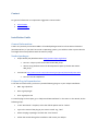
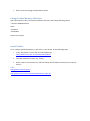
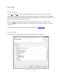
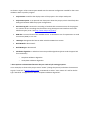
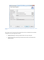
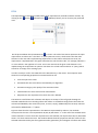
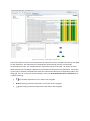
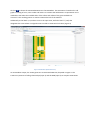
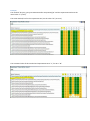
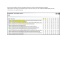
TraZer User Manual Contact For general information or cooperation suggestions contact either: Achraf Ghabi Alexander Egyed Installation Guide General Information: TraZer runs primarily on windows 64bits. All needed packages must be in that same architecture (windows 64 bits). If you don’t have such an Operating system, you could use other systems but the tool might face some problems with the memory usage Needed packages: • • Eclipse Helios (3.6) Windows 64 bit http://www.eclipse.org/helios/ • Current: eclipse-<pack>-helios-SR2-win32-x86_64.zip • We are using the RCP version for development eclipse-rcp-helios-SR1-win32x86_64.zip Java JDK 1.6 http://www.oracle.com/technetwork/java/javase/downloads/index.html • Current: Java SE 6 Update 27 Eclipse Plug-in Dependencies: To be able to install TraZer, you have to provide following plug-ins in your eclipse installation: • BIRT: org.eclipse.birt • GEF: org.eclipse.gef • Zest: org.eclipse.zest To install a plug-in into eclipse, go to “Help>Install New Software” in the menu. In the wizard, do the following steps: • In the “Work with:” drop-box, select the official update site for “Helios” • Type in the name of the plug-in you want to install. E.g., “Birt” • Select the plug-in packages and click the “next” button • Follow the wizard through the installation and restart your Eclipse • Do the same for all plug-in dependencies above. Change Eclipse Memory Allocation Open the eclipse.ini file in the eclipse installation directory and change following values: --launcher.XXMaxPermSize 512m -Xms512m -Xmx2048m Restart your eclipse Install TraZer: Go to “Help>Install New Software” in the menu. In the wizard, do the following steps: • In the “Work with:” put the link of TraZer update Site http://www.sea.uni-linz.ac.at/tools/TraZer/update/ • Click add and define a name (e.g. TraZer) • Select TraZer in the features tree and then follow the installation wizard (next, accept the license) Link: http://www.sea.jku.at/tools/ http://www.sea.uni-linz.ac.at/tools/TraZer/chess_input.zip User Guide What is TraZer? TraZer (Trace analyzer) is a tool for validating requirements-to-code traces. As input, the tool requires a requirements-to-code trace matrix (RTM) and a call graph. The matrix cells in the RTM represent the individual relationships between code (methods/functions) and requirements. The call graph reflects method/function calls in the code. TraZer is using the usual eclipse paradigm for development tools. It has, for example, its own perspective ( menu bar. ) which could be opened from “Window > Open Perspective > Others...” in eclipse In the following the functions of TraZer are demonstrated on the "Chess" project. Example Chess To start TraZer click on the new button and select the wizard “TraZer” (Figure 1) Figure 1. Selecting the wizard As shown in Figure 2 the TraZer Project Wizard sets the common configuration needed for the traces validation about a specific program: Project Name: would be the display name of the project in the eclipse workspace. Project Description: is an optional user description about the project, which should help him distinguish between different project configurations. Execution Log File: contains the recording of method calls at execution time of the program. For instance we are recording this information using the Eclipse Test & Performance Tools Platform Project (TPTP - link http://www.eclipse.org/tptp/). RTM File: is an excel sheet of the available traces. It should be a sort of requirements-to-code trace matrix (RTM) in our case. RTM Type: designates the format under which the RTM File is written. Gold RTM File: deactivated* Gold RTM Type: deactivated* Validation Algorithm: in which we have two possible algorithms (please read the paper-link for more details) o Complete Validation Algorithm o Incomplete Validation Algorithm * these options are deactivated because they are used only for testing purposes. In our example, we choose the project name "TraZer" (change the picture) and select the Execution Log File "trace.xml" (from the chess_input). As RTM File we select "trace-matrix.xls" and for the file type "Standard". As Algorithm we select "Complete Validation Algorithm". Figure 2. The TraZer Project Wizard sets the common configuration needed for the traces validation about a specific program After clicking "Finish" the project will be created and the traces are validated from the defined configuration. This process generates two files: <project_name>.cgf : containing a graphical editor of the input call graph <project_name>.rtm: representing an extended view to edit the input RTM and the validation details. Call Graph The tool enables the user to analyse single nodes in the call graph. In the “.cgf” editor the user gets a complete graphical representation of the input call graph. In our example, "Chess.cfg" would be the file to open that editor (see figure bellow). By clicking on a node the tool would highlight the code element (method) and all calling relationships (callers and callees) associated with it in the graph. Figure 3 shows the entire call graph. It depicts the calling relationships in the code, which can be inspected manually in detail. For the selected node (...initalPosition()V) the windows below show the properties and their values for the node. The Pattern View depicts the selected node and the callers and callees in the call graph. Figure 3. First Input in the Call Graph Editor RTM The Requirements Trace Matrix (RTM) editor shows requirements, methods and their relation. By clicking on the (Input), (Estimation) or (Validation) button you can choose your preferred view. On the picture below the Input RTM view ( ) is shown. The cells of the matrix represent the input requirement-to-code traces. The label “T” (Green) denotes a trace, which means that the code element on the row side is implementing requirement on the column side (and vice-versa, the requirement is implemented in the given code element). On the other side, “N” (Orange) indicates a no- trace which is the opposite of a trace. A no-trace means that the given code element is not implementing the requirement in question. We have also a third state marked as “E” (Gray) which stands for an empty cell or missing input. In order to analyse a cell in the RTM click at the desired entry in the matrix. The Properties View shows the corresponding properties associated with that cell: Link: the input trace value Estimated Link: the trace value as estimated by our algorithm. Estimation Category: The quality of the estimated value. Code Element: the exact name of the code element. Requirement: the requirement for which this cell is defined The Patterns View follows each selection and depicts an excerpt of the call graph showing the selected method and its surrounding callers and callees. In the default configuration the nodes are colored and labeled by their trace links (trace, no-trace, empty). Additionally the currently selected cell would be labeled with a “?” (Blue). Figure 4 shows that the requirements in the RTM are represented by columns, the methods correspond to the rows. The requirements R0, R3, R5, R6 show a ”T” in the row of the method which means that there is a trace from the requirement to the method, the requirements R1, R2, R4 and R7 show a “N” which means No Trace. The windows below show the properties and their values for the selected code element de.jave.chess.gameController.gameOver() and a diagram of callers and callees Figure 4.Second Input in RTM Editor (Input View) The second input to TraZer is the requirements to code traces in form of RTMs. Here we see one RTM for the illustration. The requirements in the RTM are represented by columns, the methods correspond to the rows. A”T” implies that the requirement traces to the code. ”N” implies no trace. When selected, the Call Graph is depicted all, interlaced with the given trace information. The quality of this input is unknown. The RTM view shows also information about the corresponding node in the call graph. The icon on the left of each method’s name (see Error! Reference source not found.) has a specific meaning: Blue network represents a inner node in the call graph Red starting connection represents a root node of the call graph. Green ending connection represents a leaf node in the call graph Click on to choose the Estimated RTM view in the RTM Editor. The estimation is based on the call graph consisting of roots, inner-nodes and leaves. To estimate the link between a requirement and a method the tool takes the available links of the callers and callees of the given method into account**. The resulting pattern is used to estimate the link of the method. Additionally to the labels T, N, and E as seen in the input view, we find a label “F” (Fail) that designates the cases where our algorithm was not able to estimate a link value. (Figure 5) Figure 5. RTM Editor (Estimated View) As intermediate output, the TraZer generates an Estimated RTM view, depicted in Figure 5. The TraZer uses patterns of calling relationships (input 1) and the RTM (input 2) to compute estimations. Figure 6 shows the Validated RTM view. Click on to open the Validated RTM view. This view shows the decisions taken by our algorithm. It compares between the input value and estimated value for each cell and then decides whether the given value is correct or not. Coinciding values are more likely to indicate a correct link, while conflicting ones are indication for errors. Figure 6. Validated RTM view depicts the difference between the input RTM and the estimated RTM computed by TraZer The possible entries and their meaning in the validation view are listed below: • CT: Correct entry, initially assigned value Trace (correct trace) • CN: Correct entry, initially assigned value No Trace (correct no-trace ) • IT: Incorrect entry, initially assigned value Trace (incorrect trace) • IN: Incorrect entry, initially assigned value No Trace (incorrect no trace) Example The method “de.java_cjess.java.GameController.computerPly()Z” and the requirement R0 have the initial value “T” (trace). The same method, but for the requirement R1, has the value “N” (no trace). The estimated value of this method and requirement R0 is “T”, for R1 is “N”. Since the initial values and the estimated values for both the selected method and both requirements coincide, the validation gives CT (Correct Trace) for the method and R0 and CN (Correct no-trace) for the method and R1. ** A detailed description of the algorithms used for estimation and validation can be found in the papers [1], [2] and references therein. Bibliography [1] A. Ghabi, A. Egyed, "Observations on the connectedness between requirements-to-code traces and calling relationships for trace validation.," in Automated Software Engineering (ASE), 2011 26th IEEE/ACM International Conference on SE, Lawrence, KS, USA , 2011, pp. 416 - 419.