1
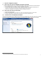
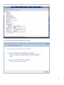
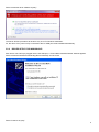
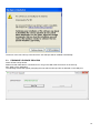
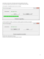
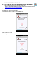
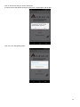
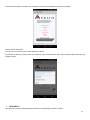
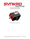
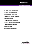
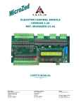
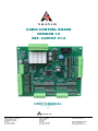
S. & A.S. LTD
CABIN CONTROL BOARD
VERSION 1.0
REF. CARTOP V1.0
USER’S MANUAL
FOR S/W VERSION 1.01
1544
S. & A. S. LTD
Beirut Office:
Boutros Building 1st Basement
Cheikh-el-Ghabi Street
Ghabi Beirut 2068 7808
Lebanon
Tel: +961 1 216 994
Fax:+961 1 339 600
Headquarters & Factory:
S. & A. S. Building
Seaside Road
Jieh Chouf
Lebanon
Tel: +961 7 996 333
Fax:+961 7 996 116
Website:
www.sascontrollers.com
Technical Support & Email:
Tel: +961 71 996 333
[email protected]
1
1 GENERAL DESCRIPTION
MAIN FEATURES
3
3
3 TECHNICAL DATA
3
4 TERMINAL DESCRIPTION
4
4.1 TERMINAL LAYOUT ............................................................................................................................................. 4
4.2 CARTOP TERMINALS .......................................................................................................................................... 5
4.3 INPUT TERMINALS .............................................................................................................................................. 5
4.4 OUTPUT TERMINALS .......................................................................................................................................... 6
4.4.1 OUTPUT TERMINALS ................................................................................................................................... 6
4.4.2 INDICATOR OUTPUT TERMINALS .............................................................................................................. 6
4.5 CALL TERMINALS ................................................................................................................................................ 6
4.6 COMMUNICATION TERMINALS CONNECTION ................................................................................................. 6
5 DESKTOP FIRMWARE UPGRADE
7
5.1 INSTALLING THE CARTOP FIRMWARE UPGRADE SOFTWARE ..................................................................... 7
5.2 INSTALLING THE CARTOP USB DRIVER .......................................................................................................... 7
5.2.1 DRIVER SETUP FOR WINDOWS VISTA/WIN7 ............................................................................................ 7
5.2.2 DRIVER SETUP FOR WINDOWS XP ........................................................................................................... 9
5.3 FIRMWARE UPGRADE PROCESS.................................................................................................................... 10
6 GOOGLE STORE FIRMWARE UPGRADE
12
6.1 INSTALLING THE SASPTOOL FIRMWARE APPLICATION ON THE MOBILE ................................................. 12
6.2 FIRMWARE UPGRADE PROCESS.................................................................................................................... 12
7 APPENDIX A
14
2
1
GENERAL DESCRIPTION
The CarTop is used with the new CAN communication interface available in the Microzed V3.5 boards. The main aim of
this interface is to simplify the elevator installation procedure and reduce the number of wires needed. Using the
CarTop, the Microzed V3.5 board receives information from the cabin and sends control signals back. Installed on the
cabin, the CarTop is used to register carcalls, process the control signals sent by the main Microzed board, read
different car information (calls,door status…) and send them back to the main Microzed board.
2
MAIN FEATURES
Platform
Communication
Firmware update
3
TECHNICAL DATA
Supply voltages
Inputs
Control outputs
Spare outputs
Call terminals
Indicator outputs
Connection
1
ARM Microcontroller
CAN Open communication interface via CAN bus
User desktop interface to upgrade firmware on site
Google store Application: SASPTool
Board supply: 24vdc +15% -25% - 120mA
Periphery supply: 22vdc +15% -25%
Each input has a led to indicate its status – all inputs are optically isolated
Input active voltage level is 22vdc
Each output has a led to indicate its status – all outputs are dry relay contacts
Rated at 250Vac 10A1
Each output has a led to indicate its status – all outputs are optically isolated
Output voltage level is 0vdc (GND) when active
Each call has a led to indicate its status
Each call terminal consists of a combined input/output which is optically isolated
Call active voltage level is zero volts (GND)
Call terminals are capable of driving lamps up to 3 watts operating on 22vdc
Each call terminal is protected by an additional output transistor
Each output has a led to indicate its status – all outputs are optically isolated
For A,B,C,D,E, LED On: Output voltage level is 22vdc (P)
For arrow up and arrow down LED On: Output voltage level is 22vdc (P)
Screw type, plug-in connectors
Care should be taken to add a freewheeling diode in parallel with the coil of each DC contactor or DC relay driven from the board.
3
TERMINAL LAYOUT
CLGT
LGHT
CSOP1
SOP1
CDOOR
OPN
CLSE
P
GND
CM
D2
D1
↑
↓
E
D
C
B
A
HALLHALL+
CARCAR+
SOP4
SOP3
SOP2
P-CAN
GND_CAN
L1
H1
L2
H2
DZ
RE OPN
CLSE
LSEO
LSEC
INSP UP
INSP DN
INSP EN
RSV
FULL
OVLD
STP
SPI1
SPI2
CT8
CT9
CT10
CT11
CT12
CT13
CT14
CT15
4.1
TERMINAL DESCRIPTION
CT0
CT1
CT2
CT3
CT4
CT5
CT6
CT7
4
4
4.2
CARTOP TERMINALS
Supply – positive side 22Vdc
Supply – negative side
P
GND
4.3
INPUT TERMINALS
DZ1
RE OPN
CLSE
LS EO
LS EC
INSP UP2
INSP DN2
INSP EN2
RSV
FULL
OVLD
FRMN
SPI1
SPI2
Door zone magnetic switch
Re-open for automatic door (when inactive) / door closed for swinging door (when active)
Bypasses reclosing delay in automatic door
Limit switch end of opening
Limit switch end of closing
Not used
Not used
Not used
Reservation – outside calls are canceled (when input is active)
Full load – only car calls are served with outside calls still being registered (when input is active)
Overload
Not used
Spare Input1
Spare Input2
In case RE OPN input is configured as normally closed, both RE OPN inputs on CartTop control and on Microzed main
control should be active to deactivate re-open. Otherwise (i.e. RE OPN is configured as normally open), re-open is
considered active when one of its corresponding inputs on the Microzed main control or the CartTop control is active.
All the other inputs are considered active when one of their corresponding inputs on the Microzed main control or the
CartTop control is active.
1
2
This terminal must be connected to DZ of Microzed in main control panel as well.
This terminal is not used, since INSP EN, INSP UP and INSP DN INPUTS are connected to Microzed main control panel.
5
4.4
OUTPUT TERMINALS
4.4.1
OUTPUT TERMINALS
Cam contactor1 / Close relay or contactor2
Open door relay or contactor2
Common for CLSE and OPN outputs
Spare output 1
Common for Spare output 1
Car light relay
Common for LGHT output
CLSE
OPN
CDOOR
SOP1
CSOP1
LGHT
CLGT
4.4.2
INDICATOR OUTPUT TERMINALS
↑
↓
A
B
C
D
E
Up direction arrow
Down direction arrow
Floor information A for Gray code indicator
Floor information B for Gray code indicator
Floor information C for Gray code indicator
Floor information D for Gray code indicator
Floor information E for Gray code indicator
4.5
CALL TERMINALS
CT15
CT14
CT13
CT12
CT11
CT10
CT9
CT8
CT7
CT6
CT5
CT4
CT3
CT2
CT1
CT0
4.6
COMMUNICATION TERMINALS CONNECTION
P-CAN
GND_CAN
L1
H1
L2
H2
1
2
Car 15
Car 14
Car 13
Car 12
Car 11
Car 10
Car 9
Car 8
Car 7
Car 6
Car 5
Car 4
Car 3
Car 2
Car 1
Car 0
CAN Supply – positive side 24Vdc (Taken from separate supply installed in Microzed panel)
CAN Supply – negative side
CAN Low
CAN High
Not used
Not used
For swinging door.
For automatic door only.
6
5
DESKTOP FIRMWARE UPGRADE
5.1
INSTALLING THE CARTOP FIRMWARE UPGRADE SOFTWARE
In order to upgrade firmware on site, a CD will be provided by S.&A.S.Ltd & the below steps shall be followed:
1. Run file “SAS_Patch.exe” located in “CarTop_PTool\SAS_PTool” folder.
2. Go to the folder “SAS_PTool_Setup” located in “MZ350_PTool\SAS_PTool” folder and double click on
“setup.exe”, then follow the instructions to setup the software “SAS_PTool.exe”.
3. “SAS_PTool” will appear in the programs list. Send it to Desktop as shortcut.
5.2
INSTALLING THE CARTOP USB DRIVER
1. Power off the CarTop board.
2. Make sure that USB cable is connected to PC. Plug in the USB cable and Power on the CarTop.
3. Follow the steps below to setup the driver according to the version of windows on PC.
5.2.1
DRIVER SETUP FOR WINDOWS VISTA/WIN71
The first CarTop plugged into the PC USB port may not launch an automatic start. In this case, right-click my computer
and choose properties. The following window appears. On the left side of the window, click on Device Manager.
1
This will be implemented only one time when the first CarTop is connected to PC through USB.
7
The CarTop device will appear in Other Devices, right-click it and choose Update Driver Software.
Select “Search automatically for updates driver software”.
8
Select “Install this driver software anyway”.
The Driver SETUP procedure will be done only once For Windows vista/Win7.
So, the driver of any new CarTop connected to the PC USB port will be installed automatically.
5.2.2
DRIVER SETUP FOR WINDOWS XP
Each time a new CarTop is plugged into the PC USB port, a “Found New Hardware Wizard” window appears.
Select “Install the software automatically (Recommended)” and click next.
Select “Continue Anyway”.
9
The driver of the new CarTop connected to the PC USB port will be installed automatically.
5.3
FIRMWARE UPGRADE PROCESS
Power off the CarTop board.
Make sure that USB cable is connected to PC. Plug in the USB cable and Power on the CarTop.
Run “SAS_PTool” application.
The following window will appear prompting the user that the CarTop board is detected on the USB port:
10
Click Open to choose the *.sas file that will be used to upgrade the firmware.
A Footnote will appear showing the file name, the software version and its date:
Click upgrade. The upgrade progress is shown as below:
Once the upgrade is complete, the footnote “Firmware upgraded successfully” will appear:
Disconnect the USB cable from CarTop
The user can now process with normal operation of the lift.
11
6
6.1
GOOGLE STORE FIRMWARE UPGRADE
INSTALLING THE SASPTOOL FIRMWARE APPLICATION ON THE MOBILE
In order to upgrade firmware from a mobile, follow the below steps:
1. Search for the application “SASPTool” on google store and install it, or follow the link below:
https://play.google.com/store/search?q=SASPTool.
6.2
FIRMWARE UPGRADE PROCESS
Run “SAS_PTool” application from the mobile.
The below window appears showing all *.sas files already saved.
Power off the CarTop board.
Use a USB cable to connect board to the mobile.
Turn CarTop on.
12
Click on the sas file that you need to download.
A Popup window will appear showing the file name, its description and its date:
Click Yes. The downloading starts:
13
Once the downloading is complete, the message “Firmware Downloaded successfully” will appear:
Disconnect the USB cable.
The user can now process with normal operation of the lift.
If you desire to delete any sas file from the mobile list, press on the filename until a Popup window appears showing you
multiple choices:
7
APPENDIX A
This appendix contains all wiring diagrams relevant to assembling the board in a panel.
14