Download - Syd-Com

Transcript
Hybrid IP PBX
Feature Guide
Model
KX-TDA100
KX-TDA200
Please read this manual before connecting the Hybrid IP PBX and save this manual for future reference.
Thank you for purchasing the Panasonic KX-TDA100/KX-TDA200, Hybrid IP PBX.
Introduction
About this Feature Guide
This Feature Guide is designed to serve as an overall feature reference for the Panasonic
Hybrid IP PBX.
It explains what this PBX can do, and how to obtain the most out of its many features and
facilities.
This manual contains the following sections:
Section 1, Call Handling Features
Provides details about the call handling features.
Section 2, System Configuration and Administration Features
Provides details about the system configuration and administration features.
Section 3, Programming
Provides system programming instructions.
Section 4, Appendix
Provides tables listing tones and ring tones.
Section 5, Index
Provide feature titles, important words to help you access the required information easily.
Terms used in this Feature Guide
Installation Manual References
The required installation instruction titles described in the Installation Manual are noted for
your reference.
Feature Guide References
The related feature titles described in this Feature Guide are noted for your reference.
User Manual References
The operation required to implement the feature described in the User Manual is noted for
your reference.
Abbreviations
There are many abbreviations used in this manual (e.g., "PT" which stands for proprietary
telephone). Please refer to Section 5 Index in this manual for the meaning of each
abbreviation.
2
Feature Guide
About the other manuals
Along with this Feature Guide, the following manuals are available to help you install, and use
this PBX:
Installation Manual
Provides instructions for installing the hardware and maintenance of the PBX.
User Manual
Provides operating instructions for end users using PTs, SLTs or DSS Consoles.
Note
There are some optional service cards, PTs, and features which are not available in some
areas. Please consult your authorised Panasonic dealer for more information.
Feature Guide
3
Feature Highlights
Automatic Route Selection (ARS)
Automatically selects the carrier available at the time an outgoing trunk call is made.
Budget Management
Limits the telephone usage to a preprogrammed budget.
Call Charge Fee Reference
Allows a user to see call charges and to print out them.
Remote Extension Lock
Allows a manager extension to lock an extension so that inappropriate trunk calls cannot be
made.
Trunk Answer From Any Station (TAFAS)
Ringing occurs over the external paging device; the call can be answered from any extension
(station).
Caller ID
Allows a user to see the name or telephone number of a caller on the telephone display before
answering a call.
ISDN Line Service
The PBX can manage calls received from ISDN lines by point-to-point or point-to-multipoint
configuration.
TIE Line Service
A TIE line is a privately leased communication line between two or more PBXs, which provides
cost effective communications between company at different locations.
E1 Line Service
The E1 line is at the bottom of the digital transmission hierarchy. The E1 line carries 30 voice
channels. Voice is digitised by Pulse Code Modulation.
4
Feature Guide
Table of Contents
1
Call Handling Features............................................................... 13
1.1
1.1.1
Incoming Call Features.......................................................................................14
Incoming Trunk Call Features—SUMMARY .........................................................14
Direct In Line (DIL) ............................................................................................................ 17
Direct Inward Dialling (DID)/Direct Dialling Inward (DDI) .................................................. 19
Multiple Subscriber Number (MSN) Ringing Service......................................................... 23
Calling Line Identification (CLI) Distribution....................................................................... 25
Intercept Routing ............................................................................................................... 27
Intercept Routing—No Destination .................................................................................... 29
Collect Call Block (only for Brazil) ..................................................................................... 30
1.1.2
Internal Call Features—SUMMARY ......................................................................32
1.1.3
Incoming Call Indication Features—SUMMARY...................................................34
Internal Call Block ............................................................................................................. 33
Ring Tone Pattern Selection ............................................................................................. 35
Call Waiting ....................................................................................................................... 37
1.2
1.2.1
1.2.2
Receiving Group Features .................................................................................38
Idle Extension Hunting ..........................................................................................38
Incoming Call Distribution Group Features—SUMMARY .....................................40
Group Call Distribution ...................................................................................................... 43
Queuing Feature ............................................................................................................... 46
VIP Call ............................................................................................................................. 48
Overflow Feature ............................................................................................................... 49
Log-in/Log-out ................................................................................................................... 51
Supervisory Feature .......................................................................................................... 53
1.3
1.3.1
Call Forwarding (FWD)/Do Not Disturb (DND) Features ..................................55
Call Forwarding (FWD)/Do Not Disturb (DND) Features—SUMMARY ................55
Call Forwarding (FWD)...................................................................................................... 57
Do Not Disturb (DND)........................................................................................................ 60
1.4
1.4.1
Answering Features............................................................................................61
Answering Features—SUMMARY ........................................................................61
Line Preference—Incoming ............................................................................................... 62
Call Pickup ........................................................................................................................ 63
Hands-free Answerback .................................................................................................... 64
1.5
1.5.1
1.5.2
1.5.3
1.5.4
1.5.5
1.5.6
1.5.7
Making Call Features ..........................................................................................65
Predialling .............................................................................................................65
Automatic Extension Release ...............................................................................66
Line Preference—Outgoing...................................................................................67
Automatic Callback Busy (Camp-On) ...................................................................68
Executive Busy Override.......................................................................................69
Intercom Call .........................................................................................................70
Second Call Notification to Busy Extension—SUMMARY ....................................71
Call Waiting Tone .............................................................................................................. 72
Off-Hook Call Announcement (OHCA) .............................................................................. 73
Whisper OHCA .................................................................................................................. 74
1.5.8
1.5.9
1.5.10
1.5.11
1.5.12
Trunk Access ........................................................................................................75
Emergency Call.....................................................................................................77
Account Code Entry ..............................................................................................78
Dial Type Selection ...............................................................................................79
Dial Tone Detection...............................................................................................80
Feature Guide
5
1.5.13 Pause Insertion..................................................................................................... 81
1.5.14 Host PBX Access Code (Access Code to the Telephone Company from a Host
PBX) ..................................................................................................................... 82
1.5.15 Special Carrier Access Code................................................................................ 84
1.6
Memory Dialling Features.................................................................................. 85
1.6.1 Memory Dialling Features—SUMMARY............................................................... 85
One-touch Dialling ............................................................................................................. 87
Last Number Redial ........................................................................................................... 88
Speed Dialling—Personal/System..................................................................................... 89
Quick Dialling..................................................................................................................... 90
Hot Line ............................................................................................................................. 91
1.7
1.7.1
1.7.2
1.7.3
1.7.4
1.7.5
1.7.6
1.8
1.8.1
1.9
1.9.1
1.9.2
1.9.3
1.9.4
1.9.5
1.9.6
1.9.7
1.9.8
1.9.9
1.9.10
1.10
1.10.1
1.11
1.11.1
1.11.2
1.11.3
1.11.4
1.12
1.12.1
1.12.2
1.12.3
1.13
1.13.1
1.14
1.14.1
1.14.2
1.14.3
1.14.4
1.14.5
1.14.6
6
Toll Restriction (TRS)/Call Barring (Barring) Features ................................... 92
Toll Restriction (TRS)/Call Barring (Barring) ........................................................ 92
Budget Management ............................................................................................ 96
Extension Lock ..................................................................................................... 97
Dial Tone Transfer................................................................................................ 98
Remote COS Access............................................................................................ 99
Verified Code Entry ............................................................................................ 100
Automatic Route Selection (ARS) Features................................................... 101
Automatic Route Selection (ARS) ...................................................................... 101
Conversation Features..................................................................................... 107
Hands-free Operation ......................................................................................... 107
Off-Hook Monitor ................................................................................................ 108
Mute.................................................................................................................... 109
Headset Operation ............................................................................................. 110
Data Line Security .............................................................................................. 111
Flash/Recall/Terminate....................................................................................... 112
External Feature Access (EFA) .......................................................................... 113
Trunk Call Limitation........................................................................................... 114
Parallelled Telephone......................................................................................... 115
Calling Party Control (CPC) Signal Detection .................................................... 117
Transferring Features ...................................................................................... 118
Call Transfer ....................................................................................................... 118
Holding Features .............................................................................................. 120
Call Hold ............................................................................................................. 120
Call Park ............................................................................................................. 122
Call Splitting........................................................................................................ 123
Music on Hold..................................................................................................... 124
Conference Features........................................................................................ 125
Conference Features—SUMMARY.................................................................... 125
Conference ......................................................................................................... 126
Privacy Release.................................................................................................. 127
Paging Features................................................................................................ 128
Paging ................................................................................................................ 128
Optional Device Features ................................................................................ 131
Doorphone Call................................................................................................... 131
Door Open .......................................................................................................... 132
Trunk Answer From Any Station (TAFAS).......................................................... 133
Background Music (BGM) .................................................................................. 134
Outgoing Message (OGM) ................................................................................. 135
Direct Inward System Access (DISA) ................................................................. 137
Feature Guide
1.15
1.15.1
1.15.2
1.16
1.16.1
1.16.2
1.17
1.17.1
1.17.2
1.17.3
1.17.4
1.18
1.18.1
Caller ID Features..............................................................................................144
Caller ID ..............................................................................................................144
Incoming Call Log ...............................................................................................148
Message Features .............................................................................................150
Message Waiting.................................................................................................150
Absent Message .................................................................................................151
Proprietary Telephone (PT) Features ..............................................................152
Fixed Buttons ......................................................................................................152
Flexible Buttons...................................................................................................156
LED Indication.....................................................................................................158
Display Information .............................................................................................160
Integrated Services Digital Network (ISDN) Service Features ......................161
Integrated Services Digital Network (ISDN)—SUMMARY ..................................161
ISDN Service Access by Keypad Protocol ...................................................................... 165
Advice of Charge (AOC).................................................................................................. 166
Call Forwarding (CF)—by ISDN (P-MP).......................................................................... 167
Call Forwarding (CF)—by ISDN (P-P)............................................................................. 169
Call Hold (HOLD)—by ISDN............................................................................................ 170
Call Transfer (CT)—by ISDN........................................................................................... 171
Calling/Connected Line Identification Presentation (CLIP/COLP)................................... 172
Malicious Call Identification (MCID)................................................................................. 174
Completion of Calls to Busy Subscriber (CCBS)............................................................. 175
ISDN Extension ............................................................................................................... 176
1.19
1.19.1
1.20
1.20.1
1.21
1.21.1
1.21.2
1.21.3
1.22
1.22.1
1.22.2
1.22.3
1.22.4
1.22.5
1.23
1.23.1
1.23.2
1.24
1.24.1
1.24.2
1.24.3
1.24.4
1.24.5
1.25
1.25.1
1.25.2
1.26
1.26.1
E1 Line Service Features..................................................................................178
E1 Line Service ...................................................................................................178
T1 Line Service Features..................................................................................180
T1 Line Service ...................................................................................................180
Voice Mail Features...........................................................................................182
Voice Mail (VM) Group........................................................................................182
Voice Mail DTMF Integration...............................................................................185
Voice Mail DPT (Digital) Integration ....................................................................191
Digital Wireless Extension (DWX) Features ...................................................195
Digital Wireless Extension (DWX) Connection....................................................195
DWX Ring Group ................................................................................................196
DWX Directory ....................................................................................................198
DWX Feature Buttons .........................................................................................199
Wireless XDP Parallel Mode ...............................................................................200
Administrative Information Output Features..................................................201
SMDR..................................................................................................................201
Charge Metre ......................................................................................................206
Extension Controlling Features.......................................................................209
Personal Password .............................................................................................209
Personal Programme Clear.................................................................................210
Walking Extension...............................................................................................211
Timed Reminder..................................................................................................212
Remote Extension Control by User.....................................................................213
Audible Tone Features .....................................................................................214
Dial Tone.............................................................................................................214
Confirmation Tone...............................................................................................215
Networking Features.........................................................................................216
TIE Line Service..................................................................................................216
Feature Guide
7
1.26.2 Virtual Private Network (VPN) ............................................................................ 235
1.26.3 QSIG Network .................................................................................................... 237
1.26.4 Voice over Internet Protocol (VoIP) Network...................................................... 239
2
System Configuration and Administration Features ............. 241
2.1
2.1.1
2.2
2.2.1
2.2.2
2.2.3
2.2.4
2.2.5
2.2.6
2.3
2.3.1
2.3.2
2.3.3
2.3.4
2.3.5
2.3.6
2.3.7
2.4
2.4.1
2.4.2
2.4.3
3
System Configuration—Hardware .................................................................. 242
Extension Port Configuration.............................................................................. 242
System Configuration—Software ................................................................... 243
Class of Service (COS) ...................................................................................... 243
Group.................................................................................................................. 244
Tenant Service ................................................................................................... 247
Time Service....................................................................................................... 250
Operator Features .............................................................................................. 254
Manager Features .............................................................................................. 255
System Data Control ........................................................................................ 256
PC Programming ................................................................................................ 256
PT Programming ................................................................................................ 258
Automatic Setup ................................................................................................. 259
Quick Setup ........................................................................................................ 260
Flexible Numbering/Fixed Numbering ................................................................ 261
Floating Extension .............................................................................................. 266
Software Upgrading............................................................................................ 267
Fault Recovery/Diagnostics ............................................................................ 268
Power Failure Transfer ....................................................................................... 268
Power Failure Restart......................................................................................... 269
Local Alarm Information...................................................................................... 270
Programming Instructions ....................................................... 273
3.1
3.2
3.2.1
3.2.2
3.2.3
3.2.4
3.2.5
3.2.6
3.2.7
3.2.8
3.2.9
3.2.10
3.2.11
3.2.12
3.3
Introduction....................................................................................................... 274
PC Programming .............................................................................................. 275
Configuration ...................................................................................................... 281
System................................................................................................................ 326
Group.................................................................................................................. 349
Line..................................................................................................................... 359
Feature ............................................................................................................... 371
Toll Restriction (TRS)/Call Barring (Barring) ...................................................... 377
Automatic Route Selection (ARS) ...................................................................... 378
Private Network .................................................................................................. 380
Incoming Call...................................................................................................... 381
Maintenance ....................................................................................................... 385
Software Version ................................................................................................ 389
Password Change .............................................................................................. 390
PT Programming............................................................................................... 391
Date & Time..................................................................................................................... 394
System Speed Dialling Number....................................................................................... 394
System Speed Dialling Name .......................................................................................... 394
Extension Number ........................................................................................................... 394
Extension Name .............................................................................................................. 394
Personal Password.......................................................................................................... 395
Operator Assignment....................................................................................................... 395
Console and Paired Telephone Assignment ................................................................... 395
8
Feature Guide
Absent Message.............................................................................................................. 395
Charge Margin................................................................................................................. 395
Charge Tax...................................................................................................................... 395
Charge Rate per Unit ...................................................................................................... 396
Flexible Numbering ......................................................................................................... 397
Time Service Switching Mode ......................................................................................... 397
Time Service Start Time .................................................................................................. 397
Automatic Trunk Group Access Assignment ................................................................... 397
System Password for Dealer ........................................................................................... 397
System Password for User .............................................................................................. 398
Manager Password ......................................................................................................... 398
Verified Code Number ..................................................................................................... 398
Verified Code Name ........................................................................................................ 398
Verified Code Password .................................................................................................. 398
Verified Code COS Number ............................................................................................ 398
Decimal Point for Currency ............................................................................................. 398
Currency .......................................................................................................................... 399
Main Processor Software Reference............................................................................... 399
Hold Recall Time ............................................................................................................. 400
Transfer Recall Time ....................................................................................................... 400
Intercept Time ................................................................................................................. 400
Hot Line Waiting Time ..................................................................................................... 400
Automatic Redial Repeat Times ...................................................................................... 400
Automatic Redial Interval ................................................................................................ 400
Door Open Duration Time ............................................................................................... 401
Call Duration Count Start Time ....................................................................................... 401
DISA Delayed Answer Time ............................................................................................ 401
DISA Extend Time ........................................................................................................... 401
DISA Intercept Time ........................................................................................................ 401
TRS/Barring Override by System Speed Dialling ............................................................ 402
TRS/Barring Denied Code............................................................................................... 402
Exception Code ............................................................................................................... 402
Special Carrier Access Code .......................................................................................... 402
Emergency Dialling Number............................................................................................ 402
ARS Mode ....................................................................................................................... 402
ARS Leading Digits ......................................................................................................... 403
ARS Routing Plan Number.............................................................................................. 403
ARS Exception Number .................................................................................................. 403
ARS Routing Plan Time Table ........................................................................................ 403
ARS Routing Plan Table (1–16) Assignment .................................................................. 403
ARS Carrier Name .......................................................................................................... 403
ARS Outgoing Trunk Group for Carrier Access............................................................... 404
ARS Removed Digits for Carrier Access code ................................................................ 404
ARS Added Number for Carrier Access code ................................................................. 404
Trunk Connection ............................................................................................................ 405
Trunk Name..................................................................................................................... 405
Trunk Group .................................................................................................................... 405
Trunk Access Number Reference ................................................................................... 405
LCOT Dialling Mode ........................................................................................................ 405
LCOT Pulse Speed ......................................................................................................... 406
LCOT DTMF Duration ..................................................................................................... 406
LCOT CPC Signal Detection Time—Outgoing ................................................................ 406
LCOT CPC Signal Detection Time—Incoming ................................................................ 406
LCOT Reverse Circuit ..................................................................................................... 406
LCOT Pause Time........................................................................................................... 406
Feature Guide
9
LCOT Flash Time ............................................................................................................ 407
LCOT Disconnect Time ................................................................................................... 407
BRI Automatic Configuration ........................................................................................... 407
BRI DIL/DID/MSN Selection ............................................................................................ 407
BRI Subscriber Number................................................................................................... 407
BRI Port Type .................................................................................................................. 407
BRI Layer 1 Active Mode................................................................................................. 407
BRI Layer 2 Active Mode................................................................................................. 408
BRI Configuration ............................................................................................................ 408
BRI TEI Mode .................................................................................................................. 408
BRI Network Type ........................................................................................................... 408
BRI Extension Tone......................................................................................................... 408
DIL 1:1 Destination .......................................................................................................... 408
DID Number..................................................................................................................... 409
DID Name ........................................................................................................................ 409
DID Destination ............................................................................................................... 409
Trunk Group Intercept Destination .................................................................................. 409
Host PBX Access Code ................................................................................................... 409
Extension-to-Trunk Call Duration Time ........................................................................... 409
Trunk-to-Trunk Call Duration Time .................................................................................. 410
DISA Silence Detection ................................................................................................... 410
DISA Continuous Tone Detection.................................................................................... 410
DISA Cyclic Tone Detection ............................................................................................ 410
Caller ID Signal Type....................................................................................................... 410
Pay Tone Signal Type ..................................................................................................... 410
Outgoing Trunk Group Number ....................................................................................... 411
TRS/Barring Level ........................................................................................................... 411
Trunk Call Duration Limitation ......................................................................................... 411
Call Transfer on Trunk Calls ............................................................................................ 411
Call Forwarding on Trunk Calls ....................................................................................... 411
Executive Busy Override ................................................................................................. 412
Executive Busy Override Deny ........................................................................................ 412
DND Override .................................................................................................................. 412
Account Code Mode ........................................................................................................ 412
Speed Dialling TRS/Barring Level ................................................................................... 412
Extension Lock TRS/Barring Level .................................................................................. 412
Manager Assignment....................................................................................................... 412
Door Open Assignment ................................................................................................... 413
Time Service Switching Mode ......................................................................................... 413
Wireless XDP Parallel Mode for Paired Telephone ......................................................... 413
Programming Mode Level ............................................................................................... 413
XDP Assignment ............................................................................................................. 414
VPS/DSS Console/PC Console Assignment ................................................................... 414
Class of Service............................................................................................................... 414
Extension Group Assignment .......................................................................................... 414
Extension Intercept Destination ....................................................................................... 414
Call Forwarding—No Answer Time ................................................................................. 415
CLIP/COLP Number Assignment .................................................................................... 415
Incoming Call Distribution Group Extension Number ...................................................... 415
Delayed Ringing .............................................................................................................. 415
Incoming Call Distribution Group Floating Extension Number ........................................ 415
Incoming Call Distribution Group Name .......................................................................... 415
Incoming Call Distribution Group Type ............................................................................ 416
Overflow Destination on Time Out................................................................................... 416
Overflow Time Assignment.............................................................................................. 416
10
Feature Guide
Overflow Destination by Busy ......................................................................................... 416
Queuing Call Limit ........................................................................................................... 416
Queuing Hurry-up Level .................................................................................................. 417
Queuing Time Table Number .......................................................................................... 417
Queuing Time Table ........................................................................................................ 417
Maximum Number of Agents ........................................................................................... 417
Paging Group for Extension Group ................................................................................. 417
Paging Group for External Pager .................................................................................... 418
Pickup Group for Extension Group.................................................................................. 418
VM Group Floating Extension Number............................................................................ 418
Idle Extension Hunting Type ........................................................................................... 418
Hunting Floating Extension Number................................................................................ 418
DWX (Digital Wireless Extension) Registration ............................................................... 419
DWX Termination ............................................................................................................ 420
DWX PIN Registration ..................................................................................................... 420
External Pager Floating Extension Number .................................................................... 421
Music Source Selection for Port 2 ................................................................................... 421
Music Source Selection for Call Hold .............................................................................. 421
Music Source Selection for Transfer ............................................................................... 421
Doorphone Call Destination ............................................................................................ 421
Door Number Reference ................................................................................................. 421
Outgoing Message (OGM) Floating Extension Number .................................................. 422
Outgoing Message (OGM) Name.................................................................................... 422
DISA Security Mode ........................................................................................................ 422
New Line ......................................................................................................................... 423
Baud Rate ....................................................................................................................... 423
Data Bits .......................................................................................................................... 423
Parity ............................................................................................................................... 423
Stop Bits .......................................................................................................................... 423
SMDR Port ...................................................................................................................... 423
SMDR Page Length ........................................................................................................ 424
SMDR Skip Perforation ................................................................................................... 424
SMDR Outgoing Call Printing .......................................................................................... 424
SMDR Incoming Call Printing .......................................................................................... 424
Remote Programming Assignment ................................................................................. 424
Modem Floating Extension Number ................................................................................ 424
ISDN Remote Floating Extension Number ...................................................................... 424
Slot Card Type Reference ............................................................................................... 425
Slot Card Deletion ........................................................................................................... 425
OPB3 Option Card Type Reference ................................................................................ 425
OPB3 Option Card Deletion ............................................................................................ 425
4
Index .......................................................................................... 427
Feature Guide
11
12
Feature Guide
Section
1
Call Handling Features
Feature Guide
13
1.1 Incoming Call Features
1.1
Incoming Call Features
1.1.1 Incoming Trunk Call Features—SUMMARY
Description
Incoming calls via a trunk (public line) are distributed to their destination using a suitable
distribution feature.
1. Available Networking Type for Each Optional Trunk Card Type
Each trunk port of an optional trunk card can be assigned its networking type: Public,
Private, or VPN (Virtual Private Network).
Networking
Type
Trunk
Card
Type
Channel Type
Public
(DIL/DID/
DDI/MSN)
LCOT
T1
E1
E&M
BRI/PRI
L-CO
G-CO
DID
TIE (E & M)
OPX (EXTN.)
DR2
E & M-C
E & M-P
E & M-C
E & M-P
CO
EXTN.
Q-SIG-Master
Q-SIG-Slave
IP-GW
Note:
*1
*2
14
Feature Guide
:
:
: Enable (default),
: Enable,
: Disable
1.26.1 TIE Line Service
1.26.2 Virtual Private Network (VPN)
Private
(TIE)*1
Virtual Private
Network
(VPN)*2
1.1 Incoming Call Features
2. Distribution Feature
One of the following features can be assigned to each trunk port:
Feature
Description
Details in
Direct In Line
(DIL)
Directs a call to a preprogrammed single
destination (e.g., Operator).
Direct Inward
Dialling (DID)
Directs a call with a DID number from a DID
line to a preprogrammed destination.
• Direct In Line
(DIL)
Direct Dialling
Inward (DDI)
• Direct Inward
Dialling (DID)/
Direct Dialling
Directs a call with a DDI number from an ISDN
Inward (DDI)
line to a preprogrammed destination.
Multiple
Subscriber
Number (MSN)
Ringing Service
Directs a call with an MSN from an ISDN line to • Multiple
a preprogrammed destination.
Subscriber
Number (MSN)
Ringing Service
3. Destination Change with the Caller’s Identification Number
The Calling Line Identification (CLI) Distribution feature works in conjunction with the DIL/
DID/DDI/MSN features
Feature
Description
Details in
Calling Line
Directs a call to a CLI destination if the caller’s • Calling Line
Identification
identification number has been assigned to the Identification
(CLI) Distribution Caller ID Table.
(CLI) Distribution
4. Available Distribution Feature for Each Optional Trunk Card Type
Trunk
Card
Type
LCOT
T1
E1
E&M
BRI
PRI
Note:
Feature
DIL
DID
DDI
MSN
Channel Type
L-CO
G-CO
DID
TIE (E & M)
DR2
E & M-C
E & M-P
E & M-C
E & M-P
CO
CO
: Enable (default),
: Enable,
: Disable
Feature Guide
15
1.1 Incoming Call Features
5. Available Destination
Destination
Availability
Wired Extension (PT/SLT/ISDN Extension/T1-OPX)
Digital Wireless Extension (DWX)
Incoming Call Distribution Group
DWX Ring Group
VM Group (DTMF/DPT)
External Pager (TAFAS)
DISA
Analogue/ISDN Remote Maintenance
Idle Trunk Access no. + Phone no.
Trunk Group Access no. + Phone no.
Other PBX Extension (TIE with no PBX Code)
Other PBX Extension (TIE with PBX Code)
6. Intercept Routing
After distribution, the following features may be required.
Feature
Intercept No Answer
Routing (IRNA)
Busy/DND
Description
Details in
If a called party does not answer a call within • Intercept
Routing
a preprogrammed period time (Intercept
time), it is redirected to the preprogrammed
destination.
If a called party is busy or in DND mode, the
call is redirected to the preprogrammed
destination.
No
If a destination is not assigned, the call is
Destination redirected to the operator.
• Intercept
Routing—No
Destination
7. Call Blocking Feature
Feature
Description
Details in
• Collect Call
Collect Call Block Rejects collect calls via the specified trunk card. Block (only for
Brazil)
16
Feature Guide
1.1 Incoming Call Features
Direct In Line (DIL)
Description
Provides automatic direction of an incoming trunk call to a preprogrammed destination. Each
trunk has a destination for each time mode (day/lunch/break/night).
[Method Flowchart]
A trunk call is received.
Does the call have its CLI*
information and is CLI mode enabled
for the trunk and the time mode?
No
Yes
CLI works.
Yes
Is the CLI destination
assigned?
No
Is the DIL destination of
the time mode assigned?
No
Yes
The call is routed to the
CLI destination.
The call is routed to the
DIL destination.
The call is routed to the
operator (Intercept Routing
—No Destination).
*: Calling Line Identification (CLI) Distribution:
If the CLI routing is enabled and the caller's identification number is assigned in the Caller ID
Table, the call will not be routed to the DIL destination, but routed to the CLI destination.
Feature Guide
17
1.1 Incoming Call Features
[Programming Example of DIL Table]
The table can be programmed for each trunk.
Trunk No.
*1
*2
Tenant
No.*1
CLI
Day
Lunch
Destination*2
Break
Night
Day
Lunch Break
01
1
Enable Disable Enable Disable
101
100
101
100
02
1
Enable Disable Disable Disable
102
100
102
100
:
:
:
:
:
:
:
:
:
:
: The time mode (day/lunch/break/night) of the programmed tenant is applied to the trunk.
:
DIL 1:1 Destination
Explanation:
If a trunk call is received from trunk 01;
In Day mode: CLI is enabled. Route to CLI destination.
In Lunch mode: CLI is disabled. Route to DIL destination, extension 100.
18
Night
Feature Guide
1.1 Incoming Call Features
Direct Inward Dialling (DID)/Direct Dialling Inward (DDI)
Description
Provides automatic direction of an incoming call with a DID/DDI number to a preprogrammed
destination. Each DID/DDI number has a destination for each time mode (day/lunch/break/
night). DID and DDI are programmed the same way. The difference between DID and DDI is
as follows:
Feature
Description
Hardware
Requirement
Direct Inward Dialling
(DID)
DID number is received using a DID line.
E1 or T1 Card
Direct Dialling Inward
(DDI)
DDI number is received using an ISDN
BRI or PRI Card
line. Point-to-point must be selected for the
ISDN configuration ( BRI Configuration).
Feature Guide
19
1.1 Incoming Call Features
[Method Flowchart]
A trunk call is received.
Is the DID/DDI number found in
the DID/DDI table?
No
The call is routed to the
operator (Intercept
Routing—No Destination).
Yes
Does the call have its CLI*
information and is CLI mode
enabled for the time mode?
No
Yes
CLI works.
Yes
Is the CLI destination assigned?
No
Is the DID/DDI destination
for the time mode assigned?
No
Yes
The call is routed to the
CLI destination.
The call is routed to the
DID/DDI destination.
The call is routed to the
operator (Intercept
Routing—No Destination).
*: Calling Line Identification (CLI) Distribution:
If the CLI routing is enabled and the caller's identification number is assigned in the Caller ID
Table, the call will not be routed to the DID/DDI destination, but routed to the CLI destination.
20
Feature Guide
1.1 Incoming Call Features
[Programming Example of DID/DDI Table]
DID and DDI use the same table.
Locat
ion
DID/DDI
No.*1
Tena
nt
No.*2
CLI
Day
DID/DDI
Destination*3
Lunc Brea Nigh
Lun Bre Nig
Day
h
k
t
ch ak
ht
DID/DDI
Name*4
0001
123-4567
1
Enab Disa Enab Disa
105 100 105 100 John White
le
ble
le
ble
0002
123-2468
1
Enab Disa
le
ble
Disa
ble
Disa
102 100 102 100 Tom Smith
ble
0003
123-456
1
Enab Disa
le
ble
Disa
ble
Disa
101 101 101 100 A company
ble
:
DID Number
: The time mode (day/lunch/break/night) of the programmed tenant is applied to the DID/
DDI number.
*3:
DID Destination
*4:
DID Name
*1
*2
Explanation:
If the DID/DDI number is "123-4567":
1. Checks the number in the table.
Matches the number in location 0001.
2. Checks the time mode.
In Day mode: CLI is enabled. Route to CLI destination.
In Lunch mode: CLI is disabled. Route to DID/DDI destination, extension 100.
The Inter-digit Time:
When the Inter-digit time expires, the PBX stops receiving DID/DDI number and starts to
check the DID/DDI table.
Even if the Inter-digit time does not expire, the PBX stops receiving the DID/DDI number when
the received number is found in the DID/DDI table. The PBX then routes the call to the
corresponding destination. If the received number matches several DID/DDI numbers in the
table, the DID/DDI number of the lowest numbered location has priority.
[Example] If a call is received in Lunch mode;
Received
Number
Destination
Explanation
123-4567
Extn. 100
The PBX finds the match in location 0001
in the table after receiving "7". So the call
is routed to extension 100.
123-456
Extn. 101
The Inter-digit time expired after
receiving "6". The PBX finds the match in
location 0003 in the table. So the call is
routed to extension 101.
Feature Guide
21
1.1 Incoming Call Features
Conditions
•
•
To use the DID or DDI service, "DID" or "DDI" must be assigned for a trunk port as the
distribution method ( BRI DIL/DID/MSN Selection *For BRI only).
DID/DDI Number Modification
It is possible to modify a received DID/DDI number, which may be convenient when
programming the DID/DDI table. Modification method (removed digit/added number) can
be programmed on a trunk port basis.
[Modification Example]
Removed digit: 6
Modified DID/DDI number: 876543 21 = 1021
Added number: 10
Received DID/DDI number: 87654321
1) Remove the
first 6 digits.
22
Feature Guide
2) Add "10".
1.1 Incoming Call Features
Multiple Subscriber Number (MSN) Ringing Service
Description
Provides automatic direction of an incoming ISDN-BRI (Basic Rate Interface) line call with an
MSN to a preprogrammed destination. One ISDN-BRI port can support a maximum of 10
MSNs. Each MSN has a destination for each time mode (day/lunch/break/night).
Point-to-multipoint must be selected for the ISDN configuration ( BRI Configuration).
[Method Flowchart]
A trunk call is received.
Are any MSNs assigned
in the MSN table?
Yes
Is the MSN found in the
MSN table?
Yes
Does the call have its CLI*
information and is CLI mode
enabled for the time mode?
No
The call is routed to the
operator (Intercept
Routing—No Destination).
No
The call is ignored.
No
Yes
CLI works.
Yes
Is the CLI destination
assigned?
No
Is the MSN destination for
the time mode assigned?
No
Yes
The call is routed to the
CLI destination.
The call is routed to the
MSN destination.
The call is routed to the
operator (Intercept
Routing—No Destination).
*: Calling Line Identification (CLI) Distribution:
If the CLI routing is enabled and the caller's identification number is assigned in the Caller ID
Table, the call will not be routed to the MSN destination, but routed to the CLI destination.
Feature Guide
23
1.1 Incoming Call Features
[Programming Example of MSN Table for ISDN BRI Port 1]
A table can be programmed for each ISDN-BRI port. Each BRI port has 10 MSN locations.
Tena
nt
No.*
CLI
MSN Destination
MSN
Name
Locat
ion
MSN
01
1234567
1
Enab Disa Enab Disa
le
ble
le
ble
101
100
101
100
A
Company
02
1232468
3
Enab Disa
le
ble
:
:
:
:
10
:
:
:
Day
Lunc Brea Nigh
Day
h
k
t
Lun Brea Nigh
ch
k
t
Disa
ble
Disa
ble
102
100
102
100
C
Company
:
:
:
:
:
:
:
:
:
:
:
:
:
:
:
:
*: The time mode (day/lunch/break/night) of the programmed tenant is applied to the MSN.
Explanation:
If the MSN "123-4567" is received from BRI port 1:
1. Checks the number in the table.
Matches the number in location 01.
2. Checks the time mode.
In Day mode: CLI is enabled. Route to CLI destination.
In Lunch mode: CLI is disabled. Route to MSN destination, extension 100.
Conditions
•
•
To use the MSN service, "MSN" must be assigned for a trunk port as the distribution
method ( BRI DIL/DID/MSN Selection).
MSN Modification
It is possible to modify a received MSN to make it shorter, which may be convenient when
programming the MSN table. Modification method (removed digit/added number) can be
programmed on a trunk port basis.
[Modification Example]
Removed digit: 6
Added number: 10
Received MSN: 87654321
•
24
Feature Guide
Modified MSN: 876543 21 = 1021
1) Remove the first
6 digits.
2) Add "10".
When using point-to-multipoint configuration with a BRI, do not connect another ISDN
terminal device in parallel with the PBX. As only two channels can be used at one time
with the BRI, the other ISDN terminal device may monopolise both channels.
1.1 Incoming Call Features
Calling Line Identification (CLI) Distribution
Description
Directs an incoming trunk call to a destination when the caller’s identification number (e.g.,
Caller ID) matches the number in the System Speed Dialling Table which is used as the Caller
ID Table. Each Caller ID (System Speed Dialling) number can have its own destination.
CLI Feature
Description
Details in
Caller ID
Caller’s number is sent from an analogue
trunk.
• 1.15.1 Caller
ID
Calling Line Identification
Presentation (CLIP)
Caller’s number is sent from an ISDN line. • Calling/
Connected
Line
Identification
Presentation
(CLIP/COLP)
Automatic Number
Identification (ANI)
Caller’s number is sent from an E1 or T1
line.
• 1.19.1 E1
Line Service
• 1.20.1 T1
Line Service
CLI always works in conjunction with the following call distribution methods:
a)
b)
c)
d)
DIL
DID
DDI
MSN Ringing Service
Each trunk (for DIL) and the DID/DDI/MSN number can enable or disable the CLI feature for
each time mode (day/lunch/break/night).
When the call has its Caller ID and the CLI is enabled for the time mode, the call will be
handled by the CLI method.
[Programming Example of System Speed Dialling Table for CLI]
*1
*2
Location
(Speed Dialling No.)
System Speed
Dialling No.*1
System Speed
Dialling Name*2
CLI Destination
000
901234567890
ABC Company
200
001
:
:
:
:
:
:
:
:
:
System Speed Dialling Number
System Speed Dialling Name
Feature Guide
25
1.1 Incoming Call Features
Explanation:
If the caller’s number is "123-456-7890" (The Trunk Access number is disregarded.):
1. Checks the number in the table.
Matches the number in location 000.
2. The call is routed to the CLI destination, extension 200.
Conditions
•
•
26
Feature Guide
The Speed Dialling Number Table assigned by each tenant is applied.
Automatic Caller ID Number Modification:
The Caller ID number is used after modification by the Automatic Caller ID Number
Modification. ( 1.15.1 Caller ID)
1.1 Incoming Call Features
Intercept Routing
Description
Provides automatic redirection of incoming trunk calls. There are two types of Intercept
Routing as follows:
Feature
Description
Intercept Routing—No If a called party does not answer a call within a preprogrammed
Answer (IRNA)
time period (Intercept time) ( Intercept Time), it is redirected
to the preprogrammed destination.
Intercept Routing—
Busy/DND
If a called party is busy or in DND mode, the call is redirected to
the preprogrammed destination.
The available intercept destination is as follows:
Type 1: The destination assigned on the extension port which the original destination joins.
( Extension Intercept Destination)
Type 2: The destination assigned on the trunk group which receives the call.
( Trunk Group Intercept Destination)
Original Destination
The Available Intercept Destination
Wired Extension (PT/SLT/ISDN
Extension/T1-OPX)
Type 1
Digital Wireless Extension (DWX)
Type 1
Incoming Call Distribution Group
Intercept Routing—Overflow in an Incoming Call
Distribution Group works ( Overflow Feature in
Section 1.2.2 Incoming Call Distribution Group
Features—SUMMARY). The overflow destination
is assigned on the incoming call distribution group
which the original destination joins ( Overflow
Destination on Time Out).
DWX Ring Group
Type 2
VM Group (DTMF/DPT)
Type 2
External Pager (TAFAS)
Type 2
DISA
Type 2*
Analogue/ISDN Remote
Maintenance
Type 2
Idle Trunk Access no. + Phone no.
Not available
Trunk Group Access no. + Phone no. Not available
Other PBX Extension (TIE with no
PBX Code)
Type 2
Other PBX Extension (TIE with PBX
Code)
Not available
Feature Guide
27
1.1 Incoming Call Features
*: This is applied only when the call does not reach the DISA line (e.g., busy), in other words,
when it does not reach the destination (e.g., extension) by using the DISA feature. Once
the call reaches the destination by using the DISA feature, the Intercept Routing feature
of the destination works.
Each of them can have different intercept destinations for each time mode (day/lunch/break/
night).
[Available Intercept Destination]
Intercept Destination
Availability
Wired Extension (PT/SLT/ISDN Extension/T1-OPX)
Digital Wireless Extension (DWX)
Incoming Call Distribution Group
DWX Ring Group
VM Group (DTMF/DPT)
External Pager (TAFAS)
DISA
Analogue/ISDN Remote Maintenance
Idle Trunk Access no. + Phone no.
Trunk Group Access no. + Phone no.
Other PBX Extension (TIE with no PBX Code)
Other PBX Extension (TIE with PBX Code)
Conditions
•
Intercept Routing—Busy/DND on/off
Each Intercept Routing—Busy and Intercept Routing—DND can be enabled or disabled
through system programming.
If disabled, one of the following is activated depending on the trunk card type which a call
arrives through:
a) LCOT or T1 (L-CO/G-CO) Card: The call will be sent back to the original destination.
b) Other Trunk Cards: Busy tone will be sent to the caller.
•
If the intercept destination cannot receive the call:
a) Intercept Routing—No answer: Intercept timer will restart at the original
destination, until the call is answered.
b) Intercept Routing—Busy/DND: The call will be sent back to the original destination
when the call arrives through the LCOT or T1 (L-CO/G-CO) Card. When the call
arrives through other trunk cards the caller will hear busy tone.
28
Feature Guide
1.1 Incoming Call Features
Intercept Routing—No Destination
Description
Provides automatic redirection of an incoming trunk call which does not have a destination
assigned. The intercept destination is an operator (tenant/PBX) ( Operator Assignment *For
PBX operator only).
Conditions
•
•
•
Intercept Routing—No Destination on/off
The Intercept Routing—No Destination feature can be enabled or disabled through
system programming.
If disabled, reorder tone will be sent to the caller. However, the Intercept Routing—No
Destination feature always works for calls through the LCOT or T1 (L-CO/G-CO) Card
even when disabled.
If an operator (tenant/system) is not assigned:
The lowest jack numbered extension will be the intercept destination.
Intercept Routing—No Destination also applies to:
Calls from doorphones.
Feature Guide
29
1.1 Incoming Call Features
Collect Call Block (only for Brazil)
Description
A collect call is rejected if the destination is assigned to reject the collect call on a COS basis.
This service is only provided with the following trunk cards:
Type 1: The service works when a collect call is received.
Type 2: The service works when a collect call is answered.
Type
Type 1
Trunk Card
Type
Description
E1*
A collect call is rejected before it arrives at the destination.
Only assignment on a COS basis for the destination is required.
LCOT
A collect call is rejected by sending the Collect Call Blocking (flash)
signal after going off-hook.
It is required to enable the Collect Call Block mode to each trunk
group first. Assignment on a COS basis for the destination is also
required.
If the telephone company does not support this service, do not
enable the Collect Call Block mode, or normal calls are also
disconnected.
E1*
Type 2
*: When the trunk card type is the E1 Card, Type 1 or Type 2 depends on the service of the
telephone company.
[Available Destination]
The destinations which can receive collect calls are as follows:
COS programming determines to enable or disable accepting collect calls (disable: Collect
Call Block mode).
Destination
Receiving
Collect Calls
Wired Extension (PT/SLT/ISDN
Extension/T1-OPX)
Required COS Assignment
COS for each extension
Digital Wireless Extension (DWX)
30
Incoming Call Distribution Group
COS for each incoming call
distribution group
DWX Ring Group
–
VM Group (DTMF/DPT)
–
External Pager (TAFAS)
–
DISA
–
Analogue/ISDN Remote Maintenance
No COS assignment required
Idle Trunk Access no. + Phone no.
–
–
Trunk Group Access no. + Phone no.
–
–
Feature Guide
1.1 Incoming Call Features
Destination
Receiving
Collect Calls
Other PBX Extension (TIE with no PBX
Code)
Other PBX Extension (TIE with PBX
Code)
Required COS Assignment
COS for each trunk group of
the destination
–
–
Conditions
[General]
•
•
The availability of this feature is depending on the service of the telephone company.
The COS assignment of the first target destination, not the answered extension, will be
effective.
[LCOT/DID/E1]
•
The Flash Signal Start time and the duration are programmable.
Feature Guide
31
1.1 Incoming Call Features
1.1.2 Internal Call Features—SUMMARY
Description
The following incoming calls reach their destination:
Feature
Description
Details in
Intercom Call
A call from one extension to another.
• 1.5.6
Intercom Call
Doorphone Call
When a call from a doorphone reaches its destination,
the recipient can talk to the visitor.
• 1.14.1
Doorphone
Call
[Available Destination]
The destinations of doorphone calls can be assigned for each time mode (day/lunch/break/
night) on a doorphone port basis ( Doorphone Call Destination).
Calling from
Destination
Extension
Wired Extension (PT/SLT/ISDN Extension/T1-OPX)
Digital Wireless Extension (DWX)
Incoming Call Distribution Group
DWX Ring Group
VM Group (DTMF/DPT)
External Pager (TAFAS)
DISA
Analogue/ISDN Remote Maintenance
Idle Trunk Access no. + Phone no.
Trunk Group Access no. + Phone no.
Other PBX Extension (TIE with no PBX Code)
Other PBX Extension (TIE with PBX Code)
32
Feature Guide
Doorphone
1.1 Incoming Call Features
Internal Call Block
Description
Internal calls can be restricted on a COS basis. Each COS of the caller can enable or disable
this feature for each COS of the called party.
[Programming Example]
Called Party
Caller
COS 1
COS 2
COS 3
...
:
:
:
:
COS 1
COS 2
COS 3
:
Explanation:
a) COS 1 can make calls to all extensions.
b) COS 2 can make calls to COS 1 only. (COS 2 cannot make calls to COS 2)
c) COS 3 can make calls to COS 3 only.
COS 1
Extn. 100
Extn. 101
COS 2
Extn. 102
COS 3
Extn. 103
Extn. 104
Extn. 105
Extn. 106
Conditions
•
•
Restricted extension numbers cannot be the parameter of the feature settings (e.g.,
Walking Extension).
All extensions can make an Operator Call regardless of the Internal Call Block.
Feature Guide
33
1.1 Incoming Call Features
1.1.3 Incoming Call Indication Features—SUMMARY
Description
Incoming calls are indicated by various methods as follows:
Type
Feature
Description
Details in
Ring Tone
Ring Tone
Pattern
Selection
A telephone rings when receiving a call. The • Ring Tone
ring tone patterns can be changed for each Pattern
incoming call type.
Selection
Voice-Calling
Alternate
Receiving—
Ring/Voice
A PT user can select to receive intercom
calls by ring tone or by voice, through
personal programming.
LED
(LED: Light
Emitting
Diode)
LED Indication The light shows line conditions with a variety • 1.17.3
of light patterns.
LED
Indication
Display
(Caller’s
Information)
Display
Information
The display shows the caller’s information.
• 1.5.6
Intercom
Call
• 1.17.4
Display
Information
External Pager Trunk Answer
from Any
Station
(TAFAS)
The external pager sends a ring tone when • 1.14.3
receiving a call.
Trunk
Answer
From Any
Station
(TAFAS)
Tone/Voice
during a
Conversation
A busy extension hears a tone, or voice from • Call
the handset/built-in speaker indicating that Waiting
another incoming call is waiting.
Call Waiting
Conditions
•
34
Feature Guide
Parallelled Telephone
With a parallelled telephone connection, two extensions ring on one extension number.
( 1.9.9 Parallelled Telephone)
1.1 Incoming Call Features
Ring Tone Pattern Selection
Description
A ring tone pattern can be selected for each incoming call type on a Ring Tone Pattern Table
basis, which can be assigned for each extension.
[Patterns]
Ring Tone Pattern
Telephone Type
Single
Double
Triple
S-Double* Option-1
Option-2
PT
Cannot be changed. Refer to the [Ring Tone
Patterns for a PT] below.
Same as
Single
Same as
Double
SLT/T1-OPX
Each pattern and its ringing cycle can be changed.
DWX
Can set the ringing pattern on the DWX based on the ring tone pattern
from the PBX.
*: S-Double can be assigned for call back ring only.
[Ring Tone Patterns for a PT]
1 280 ms
Single
(Option 1)
Double
(Option 2)
Triple
S-Double
[Programming Example of Ring Tone Pattern Table]
There are a specified number of programmable tables each of which allows the assignment
of ring tone patterns for the following incoming call types:
For trunk calls (including trunk call hold recalls) and doorphone calls, select ring tone patterns
on a trunk group or a doorphone port basis.
Intercom
Table
Call/Hold
No.
Recall
Trunk Call/Hold
Recall
TRG1
TRG2
...
Doorphone Call
Port 1 Port 2
1
Double
Single
Single
2
Single
Double
Double
:
:
:
:
:
:
:
Sens Alar Call
LCS
or
m Back
...
:
:
:
:
:
Each extension can select one of the tables.
Feature Guide
35
1.1 Incoming Call Features
Conditions
•
36
Feature Guide
The "bell off" setting can be enabled or disabled for PT through system programming. If
disabled, PT users cannot set the bell off.
1.1 Incoming Call Features
Call Waiting
Description
Used to inform a busy extension that another incoming call is waiting. The busy extension user
can answer the second call by disconnecting the current call or placing it on hold.
The following notification method can be assigned for each extension depending on the call
waiting and the telephone type:
a)
b)
c)
d)
Call Waiting Tone: Tone from the handset or built-in speaker
OHCA: Voice from the built-in speaker
Whisper OHCA: Voice from the handset
Off: No notification.
Notification Method
Call Type
DPT
Other Telephone
Intercom call
Call Waiting tone/OHCA/ Call Waiting tone/Off
Whisper OHCA/Off
Trunk call*
Call Waiting tone/Off
*: Including a doorphone call, call from an incoming call distribution group, and a call from
an extension that placed a trunk call on a consultation hold.
This feature is also known as Busy Station Signalling (BSS).
Conditions
•
•
•
•
•
Call Waiting call for a VM group (DPT/DTMF) member is not available.
Data Line Security
Setting Data Line Security cancels the Call Waiting setting.
Call Waiting Tone
A PT user can set different Call Waiting tones for each trunk call and intercom call through
personal programming (Call Waiting Tone Type Selection).
Caller Information
With the Call Waiting tone, the caller’s information flashes on the display for five seconds
at 15-second intervals.
Call Waiting from the Telephone Company
Besides the Call Waiting service within the PBX, the Call Waiting tone offered by an
analogue line from your telephone company informs the extension user of another
incoming trunk call that is waiting. He can answer the second call by disconnecting the
current call or placing it on hold. For details, consult your telephone company.
Visual Caller ID:
With the Call Waiting tone from the telephone company, the Caller ID number can be
received and flash on the display twice for five seconds at 15-second intervals.
Feature Guide
37
1.2 Receiving Group Features
1.2
Receiving Group Features
1.2.1 Idle Extension Hunting
Description
If a called extension is busy or in DND mode, Idle Extension Hunting redirects the incoming
call to an idle member of the same idle extension hunting group, which can be programmed
through system programming ( Hunting Floating Extension Number). Idle extensions are
automatically searched according to a preprogrammed hunting type ( Idle Extension
Hunting Type).
This feature is also known as Station Hunting.
Type
Circular Hunting
Description
An idle extension is searched for in the order specified in the idle
extension hunting group in a circular way.
Incoming call
Busy
Extn.
Extn.
Extn.
Extn.
Assigned order
Terminated
Hunting
An idle extension is searched for in the order specified in the idle
extension hunting group until reaching the last assigned extension.
Incoming call
Extn.
Busy
Extn.
Extn.
Extn.
Assigned order
Conditions
•
•
38
Feature Guide
Idle Extension Hunting applies to:
Intercom, trunk, and doorphone calls to a single destination.
An extension user can belong to only one idle extension hunting group.
1.2 Receiving Group Features
•
If all the searched extensions are busy:
The PBX redirects the call to an overflow destination which can be assigned for each idle
extension hunting group.
[Available Destination]
Destination
Availability
Wired Extension (PT/SLT/ISDN Extension/T1-OPX)
Digital Wireless Extension (DWX)
Incoming Call Distribution Group
DWX Ring Group
VM Group (DTMF/DPT)
External Pager (TAFAS)
DISA
Analogue/ISDN Remote Maintenance
Idle Trunk Access no. + Phone no.
Trunk Group Access no. + Phone no.
Other PBX Extension (TIE with no PBX Code)
Other PBX Extension (TIE with PBX Code)
•
FWD/DND Mode
While searching for an idle extension within an idle extension hunting group, any
extension which has set FWD—All Calls or DND feature will be skipped, and the call will
go to the next extension in the group.
Feature Guide
39
1.2 Receiving Group Features
1.2.2 Incoming Call Distribution Group Features—
SUMMARY
Description
An incoming call distribution group is a group of extensions programmed through system
programming ( Incoming Call Distribution Group Extension Number). An incoming call
distribution group receives calls directed to the group. Each incoming call distribution group
has a floating extension number.
Incoming calls directed to an incoming call distribution group are distributed to the member
extensions in the group using a distribution method. When a preprogrammed number of
extensions in the group are busy, the incoming calls can wait in a queue.
Each incoming call distribution group and member extensions can be programmed as desired
to handle incoming calls. Calls to the group can be monitored by an extension assigned as a
supervisor (supervisor extension).
Programming Item Example for Incoming Call Distribution Group 1 with
Diagramme
A through F in the table are described in the following diagramme.
A
Group
No.
1
2
3
:
Floating
Extn. No.*1
290
291
Group
Name*2
Sales
Engineering
B
Distribution
Method*3
Ring
UCD
C
Answering
Agent*4
3
Max
D
Queuing
Call*5
3
8
E
Hurry-up
Level*6
3
8
F
Overflow
Time*7
60
90
Overflow Destination*8
... ... Night
Day
... ... 100
100
... ... 200
200
Tenant
No.*9
1
5
:
Incoming Call Distribution Group Floating Extension Number
:
Incoming Call Distribution Group Name
*3:
Incoming Call Distribution Group Type
*4:
Maximum Number of Agents
*5:
Queuing Call Limit
*6:
Queuing Hurry-up Level
*7
:
Overflow Time Assignment
*8
:
Overflow Destination on Time Out/Overflow Destination by Busy
*9
: Tenant number is required to determine the time mode (day/lunch/break/night) and the
music source (for Music on Hold) for each group.
*1
*2
40
Feature Guide
1.2 Receiving Group Features
Calls arriving at incoming call
distribution group 1.
7
6
D Queuing Feature
F Overflow Feature
a) Sends busy tone (Busy on Busy), or
b) Redirects to the overflow destination.
5
Three calls are
waiting in a queue.
4
3
B Group Call Distribution
Calls are distributed by the
assigned method.
(Only three extensions
[agents] can answer the
call for Busy on Busy
C .)
2
1
E Manual Queue Redirection *10
The longest waiting call in a queue
can be redirected to the overflow
destination by pressing the Hurry-up
button. The button shows the Hurryup status.
Supervisor Extension*11
Extn.
100
Extn.
101
Monitors or controls the
incoming call distribution
group status.
Extn.
102
Extn.
103
Extn.
104
A Incoming Call
Extn.
105
Log-in
Extn.
105
Log-out *12
Distribution Group 1
(Floating extension no.: 290,
Name: Sales)
Queuing Feature in Section 1.2.2 Incoming Call Distribution Group Features—
SUMMARY
*11
:
Supervisory Feature in Section 1.2.2 Incoming Call Distribution Group Features—
SUMMARY
*12
:
Log-in/Log-out in Section 1.2.2 Incoming Call Distribution Group Features—
SUMMARY
*10
:
1. Group Call Distribution [
Group Call Distribution in Section 1.2.2 Incoming Call
Distribution Group Features—SUMMARY]
Incoming calls are distributed using one of the following methods:
Distribution Method
Description
Uniform Call
Distribution (UCD)
Calls go to a different extension uniformly each time a call
is received.
Priority Hunting
An idle extension is searched in the specified order.
Ring
All extensions in the incoming call distribution group ring
simultaneously.
2. Queuing Feature [
Queuing Feature in Section 1.2.2 Incoming Call Distribution Group
Features—SUMMARY]
If a preprogrammed numbers of extensions in an incoming call distribution group are
busy, a preprogrammed number of additional calls can wait in a queue.
While calls are waiting in the queue, an outgoing message (OGM) or Music on Hold can
Feature Guide
41
1.2 Receiving Group Features
be sent to the waiting callers.
3. VIP Call [
VIP Call in Section 1.2.2 Incoming Call Distribution Group Features—
SUMMARY]
It is possible to assign a priority to incoming call distribution groups so that an incoming
call can be received from the groups in priority order.
4. Overflow Feature [
Overflow Feature in Section 1.2.2 Incoming Call Distribution
Group Features—SUMMARY]
A call is redirected to a preprogrammed destination when it cannot be answered or
queued (Intercept Routing—Overflow in an Incoming Call Distribution Group). It is
also possible to send busy tone (Busy on Busy) or disconnect the line.
5. Incoming Call Distribution Group Controlling Feature
Feature
Description
Details in
Log-in/Log-out
Member extensions can join the group to • Log-in/Loghandle calls (log-in) or leave the group out
for a break (log-out).
They can leave the group temporarily
when they are away from their desks, to
prevent calls being sent to their
extensions.
Supervisory Incoming
Feature
Call Queue
Monitor
The supervisor extension can monitor
various information about the incoming
calls for each incoming call distribution
group on his display.
Log-in/Logout Monitor
and Remote
Control
• Supervisory
Feature
Monitor: The supervisor extension can
monitor the log-in/log-out status of the
group members.
Remote Control: The supervisor
extension can change the status of the
members.
Conditions
•
•
•
42
Feature Guide
One extension can belong to multiple incoming call distribution groups.
G-DN button
A Group Directory Number (G-DN) button can be assigned on a flexible button for each
incoming call distribution group. It receives the incoming calls to the group.
One extension can have more than one G-DN button of the same or different incoming
call distribution groups (Multiple G-DN). If all G-DN buttons in the same incoming call
distribution group are occupied, the next incoming call will be held in a queue or will
overflow. If the G-DN is not assigned, incoming calls will arrive at the INTERCOM or CO
button.
Even though an extension can have a G-DN button for an incoming call distribution group
that the extension has not been programmed to be included through system programming
( Incoming Call Distribution Group Extension Number), the G-DN button will not receive
calls to that group.
Group FWD
The FWD feature can be assigned on an incoming call distribution group basis.
1.2 Receiving Group Features
Group Call Distribution
Description
The Incoming calls directed to an incoming call distribution group are distributed to the
member extensions using the distribution method until a preprogrammed number of
extensions (agents) ( Maximum Number of Agents) are available to accept a call. When
incoming calls exceed the number, the calls enter a queue ( Queuing Feature in Section
1.2.2 Incoming Call Distribution Group Features—SUMMARY).
1. Distribution Method
There are three distribution methods which can be assigned to each incoming call
distribution group ( Incoming Call Distribution Group Type).
Distribution
Method
Uniform Call
Distribution
(UCD)
Description
Calls go to a different extension uniformly each time a call is
received. Extensions are hunted in a circular way in the
preprogrammed order for the group, starting at the extension after
the extension which received the last call.
Received
the last call.
Extn.
D
Extn.
C
Extn.
B
Extn.
A
Starts searching from
extn. B. (Skips extn. A.)
Priority Hunting An idle extension is searched for using the preprogrammed order
for the group.
1st Priority
2nd Priority 3rd ....
Extn.
B
Extn.
A
Extn.
C
Extn.
D
Always starts searching from
the first assigned extension.
Ring
All extensions in the group ring simultaneously.
Delayed Ringing:
Delayed ringing or no ringing can be programmed for each
extension in the group ( Delayed Ringing). The call can be
answered by pressing the flashing button even if no ring or a
delayed time is set.
Extn.
A
Extn.
B
Extn.
C
Rings immediately simultaneously.
Extn.
D
Delayed Ringing:
Rings after a
specified time delay.
Feature Guide
43
1.2 Receiving Group Features
2. Call Waiting for Incoming Call Distribution Group (Group Call Waiting)
When there are no available extensions in distribute in a group, the group members can
receive the Call Waiting tone. To use this feature:
•
Select the Group Call Waiting mode through system programming. This determines
the distribution method for waiting calls.
•
Member extensions must assign the Call Waiting mode individually, or they will not
be notified. ( Call Waiting in Section 1.1.3 Incoming Call Indication Features—
SUMMARY)
[How the Group Call Waiting Feature Activates]
Programming Conditions
Result
Group Call
Group Call
Waiting Mode Distribution Method
Distribution
UCD
Priority Hunting
Ring
All
UCD/Priority Hunting/
Ring
Group Call Waiting
Capable
Distribution Method
Telephone
PT/DWX with
UCD
idle G-DN button
Priority Hunting
Any telephone
Ring*
*: Delayed Ringing is not available.
[Example]
• Group Call Waiting mode: All
• Group call distribution method
for idle extensions: UCD
All extensions hear the Call
Waiting tone (Ring).
[G-DN Button for Group Call Waiting]
The way that the Group Call Waiting feature works depends on the Group Call Waiting
Distribution method as follows:
a) Ring: The Group Call Waiting feature activates for all busy member extensions
(even when the extensions do not have G-DN buttons) simultaneously for only
one incoming call — additional calls will wait in a queue.
b) UCD/Priority Hunting: The Group Call Waiting feature activates on an idle GDN button located on busy member extensions in a certain order. (This order
depends on the type; UCD or Priority Hunting.) Calls will arrive at idle buttons
until all G-DN buttons are occupied — additional calls will wait in a queue.
Note
In the method b), if an extension has only one G-DN button for an incoming call
distribution group, the Group Call Waiting feature for the group will not work at
the extension.
44
Feature Guide
1.2 Receiving Group Features
Incoming Call
Distribution
Group 1
(Floating
extension
no.: 200)
3
2
Incoming Call
Distribution
Group 2
(Floating
extension
no.: 300)
1
G-DN200 (Call Waiting)
G-DN300 (Answering the Call)
3. No Reply Redirection (UCD or Priority Hunting Method)
If a call received at a member extension is not answered within a preprogrammed time
period (No Answer time), the call will be redirected to the next member extension. If there
is no idle group member, the call queues at target extension until a group member
becomes available.
Conditions
•
•
FWD/DND Extension
System programming for each incoming call distribution group is required to skip or ring
the extension which has FWD or DND feature set. If it rings, the FWD/DND settings are
ignored.
Group Call Waiting feature cannot be used with the VIP Call feature ( VIP Call in
Section 1.2.2 Incoming Call Distribution Group Features—SUMMARY) and/or Wrap-up
feature ( Log-in/Log-out in Section 1.2.2 Incoming Call Distribution Group Features—
SUMMARY). Because to use the VIP Call feature and/or Wrap-up feature, Call Waiting
mode on each extension should be off.
Feature Guide
45
1.2 Receiving Group Features
Queuing Feature
Description
When a preprogrammed number of extensions ( Maximum Number of Agents) in an
incoming call distribution group are busy, additional incoming calls can wait in a queue. The
number of calls which can be in the waiting queue is programmable ( Queuing Call Limit).
While calls are waiting in the queue, the calls are handled by the Queuing Time Table, which
can be assigned for each time mode (day/lunch/break/night) ( Queuing Time Table
Number). Each Queuing Time Table has a specified number of sequences. The following
procedures are provided to make up a Queuing Time Table:
[Procedure Table]
Command
Description
OGM a
Condition
An outgoing message (OGM) a
(01-64) is sent to the caller.
b × 5 sec
After the outgoing message (OGM),
Music on Hold will be sent and redirects
to the next sequence.
Puts the caller in the waiting
If an outgoing message (OGM) has not
queue for b (01-16) × 5 seconds. been sent to the caller, the caller hears
a ringback tone.
If an outgoing message (OGM) has
been sent to the caller, the caller hears
Music on Hold.
Seq c
Redirects to sequence c (01-16). None
Intercept
Redirects to overflow destination. None
Disconnect
Disconnects the line.
None
None
Redirects to the next sequence.
(No command)
If assigned on sequence 01, the Time
Table will not be activated.
[Programming Example of Queuing Time Table]
Time
Table
No.
Sequence*1
Seq.01
Seq.02
Seq.03
Seq.04
01
OGM 01
6 × 5 sec
OGM 03
Overflow
:
:
:
:
...
Seq.16*2
:
:
02
03
:
*1
*2
46
: Queuing Time Table
: The call will be disconnected if the destination is not determined after sequence 16.
Feature Guide
1.2 Receiving Group Features
Explanation for Queuing Time Table 01:
Queuing Time Table 01
Seq. 01
The call
queues.
Seq. 02
OGM 01 is sent.
Thank you for
calling Panasonic.
The department you
are calling is busy.
Please hold the line.
We will answer your
call shortly.
Music on Hold
is sent for 30
seconds.
Seq. 03
OGM 03 is sent.
We are sorry to
keep you holding.
The department
is still busy. We
are transferring
you to the
operator.
Seq. 04
Redirects to
the overflow
destination.
Overflow
destination
answers.
The call is connected to the member
extension as soon as he answers the
queued call.
Conditions
•
•
•
If the call is transferred to the incoming call distribution group and is handled by
the Queuing Time Table:
Transfer Recall will not occur even if the Transfer Recall time expires.
Manual Queue Redirection
It is possible to redirect the longest waiting call in a queue to the overflow destination by
pressing the Hurry-up button. (When the call is already ringing on any extension, the call
is not redirected.)
This feature is also known as Hurry-up Transfer.
Hurry-up Button
A flexible button can be customised as the Hurry-up button. The number of calls queuing
before Manual Queue Redirection may be performed is programmable ( Queuing
Hurry-up Level). The button shows the current status as follows:
Light Pattern
Calls in the Waiting Queue
Off
No queued call
Red on
One up to the assigned number for Hurry-up
Rapid red flashing
Over the assigned number for Hurry-up
Feature Guide
47
1.2 Receiving Group Features
VIP Call
Description
It is possible to assign a priority to incoming call distribution groups. If an extension belongs
to multiple groups and the extension becomes idle, queuing calls in the groups will be
distributed to the extension in priority order.
Each incoming call distribution group can enable or disable the VIP Call mode. When multiple
groups enable the VIP Call mode, the incoming call distribution group with the lowest
numbered group has the highest priority. When multiple groups disable the VIP Call mode,
queuing calls are distributed to extensions uniformly.
[Example]
In the call centre, incoming call distribution groups 1 and 3 enable the VIP Call mode, while
incoming call distribution groups 2 and 4 disable the VIP Call mode.
Calls have been distributed by DIL/DID/DDI/CLI.
(The number in the circle is the queuing order.)
Incoming Call
Distribution
Group 1
(for VIP)
6
1
Incoming Call
Distribution
Group 2
(for general
customers)
Incoming Call
Distribution
Group 3
(for special
customers)
5
3
3rd
Priority
1st
Priority
Extn.
101
Extn.
102
4
2
2nd
Priority
Incoming Call
Distribution
Group 4
(for general
customers)
7
6
3rd
Priority
Extn.
103
Distribution order: 1
6
2
4
From: Group 1 Group 3
48
Feature Guide
3
6
5
7
Groups 2 and 4
1.2 Receiving Group Features
Overflow Feature
Description
When waiting calls exceed the waiting queue capacity ( Queuing Call Limit), they may be
redirected to a preprogrammed destination or busy tone may be sent to the callers by the
following features:
1) Intercept Routing—Overflow in an Incoming Call Distribution Group
2) Busy on Busy
1. Intercept Routing—Overflow in an Incoming Call Distribution Group
The Intercept Routing—Overflow in an Incoming Call Distribution Group works in one of
following conditions:
a)
b)
c)
d)
e)
There is no space in the waiting queue.
The Queuing Table is not assigned and there are no extensions logged-in.
An Intercept command is assigned to the Queuing Time Table.
The Overflow time (
Overflow Time Assignment) expires.
Manual Queue Redirection is performed.
[Available Destination]
The overflow destinations can be assigned for each incoming call distribution group and
each time mode (day/lunch/break/night). The two different destinations can be assigned,
one for the a) and b) ( Overflow Destination by Busy), and one for c), d), and e) (
Overflow Destination on Time Out).
Destination
Availability
Wired Extension (PT/SLT/ISDN Extension/T1-OPX)
Digital Wireless Extension (DWX)
Incoming Call Distribution Group
DWX Ring Group
VM Group (DTMF/DPT)
External Pager (TAFAS)
DISA
Analogue/ISDN Remote Maintenance
Idle Trunk Access no. + Phone no.
Trunk Group Access no. + Phone no.
Other PBX Extension (TIE with no PBX Code)
Other PBX Extension (TIE with PBX Code)
Feature Guide
49
1.2 Receiving Group Features
2. Busy on Busy
The Busy on Busy feature works when the destination for the Intercept Routing—
Overflow in an Incoming Call Distribution Group feature is not assigned in one of the
following conditions:
a) There is no space in the Waiting queue.
b) The Queuing Table is not assigned and there are no extensions logged-in.
[Example of a)]
When the answering agent number ( Maximum Number of Agents) is "2", and the
queuing call number ( Queuing Call Limit) is "0":
There are five assistants in the shop. If two of them are engaged on the phone, the next
caller will hear busy tone to prevent the caller from thinking that there is no one in the shop
or that the shop is closed.
Conditions
[Intercept Routing—Overflow in an Incoming Call Distribution Group]
•
If the Overflow time expires, and the overflow destination is unavailable:
If the trunk call arrives through the LCOT or T1 (L-CO/G-CO) Card: The line is
disconnected.
If the call arrives through the other cards: Redirection is ignored and the Overflow timer
activates again.
[Busy on Busy]
•
50
Feature Guide
If a trunk call arrives through the LCOT or T1 (L-CO/G-CO) Card, busy tone will not be
sent to the caller.
1.2 Receiving Group Features
Log-in/Log-out
Description
Incoming call distribution group members can join (log-in) or leave (log-out) the groups
manually.
They can leave the group temporarily when they are away from their desks, to prevent calls
being sent to their extensions. They can return to the group when they are ready to answer
calls.
Wrap-up:
While logged-in, a member extension can have a preprogrammed time period automatically
for refusing calls after completing the last call (Wrap-up time). While Wrap-up timer is active,
calls to all incoming call distribution groups to which the extension belongs will skip the
extension so that he can make some report or etc.
Wrap-up mode can also be activated manually (Not Ready) by pressing the Wrap-up button.
[Log-in/Log-out and Wrap-up Status Example]
<When the incoming call distribution group is in Priority Hunting distribution method>
Incoming call
Ready
Log-in
Waiting for a call
Press the
Wrap-up button.
Extn.
101
Extn.
102
Ready
Extn.
103
Extn.
104
Extn.
105
Extn.
106
Answering a call
The Wrap-up
time expires.
Not Ready
Making a report/
temporary break
Ready Not Ready Wrap-up Ready
After
completing
the call
Press the
Wrap-up button.
Wrap-up
Making a report
Extn.
102
Log-out
Conditions
•
•
Generally, there should be at least one extension in a group that is logged-in. However,
all extensions can log-out if permitted through system programming.
Log-in/Log-out Button
A flexible button can be customised as the Log-in/Log-out button with the following
parameters:
Light Pattern
Parameter
Usage
Red on
No parameter
Used with a G-DN button
—
Off
—
Specified incoming Used to log-in or log-out from the
Log-out
call distribution
specified incoming call distribution group. Status
group number
Log-in
Status
Feature Guide
51
1.2 Receiving Group Features
Light Pattern
Parameter
Usage
Red on
(All)
•
•
Used to log-in or log-out from all incoming After Log- After Logcall distribution groups to which you
out
in
belong.
Operation Operation
If a G-DN button is assigned, it also shows the log-in/log-out status of the corresponding
group. The light pattern is the same as the Log-in/Log-out button which includes the group
number.
Wrap-up Button
A flexible button can be customised as the Wrap-up button. It shows the current status as
follows:
Light pattern
•
•
•
52
Feature Guide
Off
Status
Slow red flashing
Wrap-up
Red on
Not Ready
Off
Ready (Wrap-up mode cancel)
Automatic Log-out
A member extension may be logged-out automatically, if the Unanswered time expires a
preprogrammed number of times consecutively. The number of consecutive unanswered
calls can be assigned for each incoming call distribution group. If the extension is a
member of more than one incoming call distribution group, the unanswered number is
counted across all corresponding incoming call distribution groups. It is possible to return
to the log-in mode manually.
Log-in/Log-out Monitor
The supervisor extension can monitor and control the log-in/log-out status of the incoming
call distribution group members. ( Supervisory Feature in Section 1.2.2 Incoming Call
Distribution Group Features—SUMMARY)
Log-in/Log-out Information on SMDR
Log-in/Log-out information can be printed out on SMDR. ( 1.23.1 SMDR)
1.2 Receiving Group Features
Supervisory Feature
Description
An extension preprogrammed as a supervisor (supervisor extension) can monitor and control
the each member’s status within the incoming call distribution group using a 6-line display PT.
Feature
Description
Incoming Call Queue The supervisor extension can monitor the status of an incoming
Monitor
call distribution group with the display.
Log-in/Log-out
Monitor and Remote
Control
Monitor: The supervisor extension can monitor the log-in/log-out
status of the incoming call distribution group members through the
corresponding DSS button light.
Remote Control: The supervisor extension can change the status
of the members by pressing the corresponding DSS button.
[Example]
<Incoming Call Queue Monitor Display>
31 Jan. 08:13AM FRI
250:Sales Section
Waiting Calls Now :00006
Max. Waiting Time :05'10
EXIT
LOG
--- Date and time
--- Floating extension number/name of incoming call distribution group
--- The number of queuing calls
--- The longest queuing time
SPRVS
Since 29 JAN. 09:10AM --- Monitoring starting date and time
Total Calls
:00996 --- Total number of incoming calls
Overflow Calls
:00131 --- Total number of overflowed calls
Lost Calls
:00039 --- The number of lost calls
Average Waiting
:02'12 --- Average queuing time
EXIT
CLEAR
<Log-in/Log-out Monitor/Remote Control Mode with DSS Button light>
31 Jan. 08:13AM FRI
250:Sales Section
Waiting Calls Now :00006
Max. Waiting Time :05'10 With
EXIT
Log-in/Log-out Monitor
DSS buttons of the incoming call
distribution group members show
their status.
Log-in/Log-out Remote Control
Pressing the button changes
the status as follows:
Lighting pattern Status
Status
Light pattern
Green on
Log-out
Red on
Log-in (Ready)
Slow Green Flashing Log-in (Not Ready/Wrap-up)
Red on
Log-out
Off
Extension in another
incoming call distribution
group
Log-in (Ready) Green on
Feature Guide
53
1.2 Receiving Group Features
Conditions
•
Available Extension as a Supervisor Extension
a) One supervisor extension can be assigned for each incoming call distribution group,
but it need not belong to the group.
b) One extension can be the supervisor extension of more than one incoming call
•
•
•
•
54
Feature Guide
distribution group.
Available Paired DSS Console
The KX-T7640 is only available for this feature.
Accumulation Value Clear
Accumulation value (total incoming calls/total overflowed calls/lost calls/average queuing
time) can be cleared manually. The date and time of clearing is saved and it is shown on
the display (monitoring starting date and time). When the value exceeds 99999, before
clearing, "****" will be shown.
If a call to an incoming call distribution group is overflowed:
If the display is in idle status, it will change to monitor mode for the corresponding
incoming call distribution group automatically.
If the display is monitoring another incoming call distribution group, it will not change.
Other Features while in Monitor Mode
The supervisor extension can use other features (making calls, pressing the MESSAGE
button, etc.) even while in monitor mode. When each operation is finished, his telephone
returns to the queue monitor display.
1.3 Call Forwarding (FWD)/Do Not Disturb (DND) Features
1.3
Call Forwarding (FWD)/Do Not Disturb
(DND) Features
1.3.1 Call Forwarding (FWD)/Do Not Disturb (DND)
Features—SUMMARY
Description
When an extension user cannot answer calls (e.g., busy, not at the desk), it is possible to
forward or refuse the calls using the following features:
1) Call Forwarding (FWD)
2) Do Not Disturb (DND)
1. FWD
Extensions and incoming call distribution groups can forward their incoming calls to preset
destinations.
2. DND
An extension user can send the tone to let the caller know he is not available.
Conditions
•
•
•
FWD and DND features apply to:
Intercom calls (including doorphone calls), and trunk calls (including a call from an
extension that placed a trunk call on a consultation hold.)
FWD/DND Button
Both the FWD and DND features for the extension can be customised on a flexible button.
Only one of the features will work at a time.
Multiple types of FWD/DND buttons can be customised on an extension.
Group FWD Button
The FWD feature for the incoming call distribution group can be customised on a flexible
button. Multiple types of Group FWD buttons can be customised on an extension.
[FWD/DND Button and Group FWD Button Types]
Type
FWD/DND for FWD/DND—Internal
Extension
FWD/DND—External
FWD/DND—Both
Group FWD—Internal
FWD for
Incoming Call
Group FWD—External
Distribution
Group
Group FWD—Both
Description
Works for incoming intercom calls
Works for incoming trunk calls
Works for all incoming calls
Works for incoming intercom calls
Works for incoming trunk calls
Works for all incoming calls
[Button Status]
The FWD/DND button and Group FWD button show the current status as follows:
The pattern can be changed through system programming.
Feature Guide
55
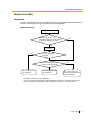
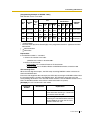
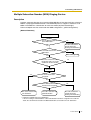
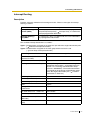
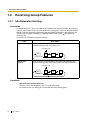
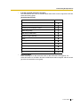
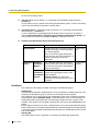
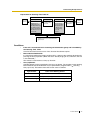
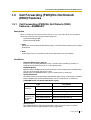
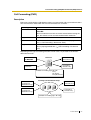
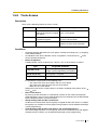
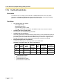
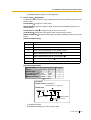
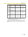
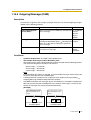
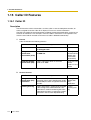
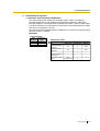
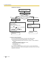
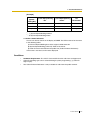
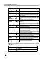
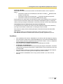
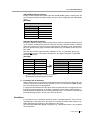
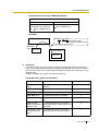
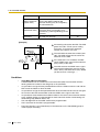
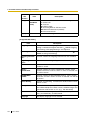
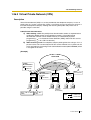
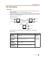
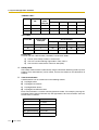
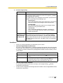
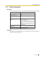
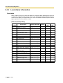
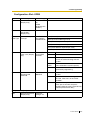
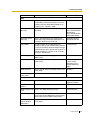
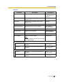
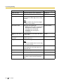
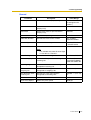
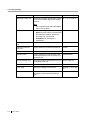
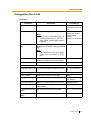
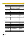
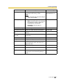
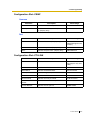
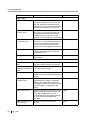
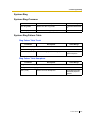
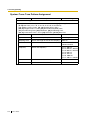
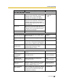
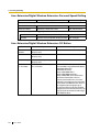
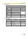
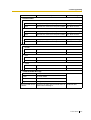
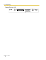
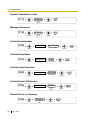
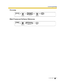
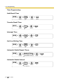
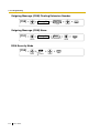
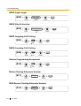
1.3 Call Forwarding (FWD)/Do Not Disturb (DND) Features
Light pattern
Status (default)
Red on
FWD on
Slow red flashing
DND on
Off
FWD/DND off
[Mode Change]
When either the FWD or DND feature is assigned, pressing the FWD/DND button
changes the on/off setting alternately. When both the features are assigned
simultaneously, pressing the button changes the settings as follows:
FWD
56
Feature Guide
DND
Off
1.3 Call Forwarding (FWD)/Do Not Disturb (DND) Features
Call Forwarding (FWD)
Description
Extensions and incoming call distribution groups can forward their calls to preset destinations.
The circumstances under which the calls are forwarded are as follows:
Type
Circumstance
All Calls
Any time
Follow Me:
When an extension user fails to set this feature before leaving the
desk, this feature can be set from the destination extension.
Busy
When the extension user’s line is busy.
No Answer
When the extension user does not answer within a preprogrammed
time ( Call Forwarding—No Answer Time).
Busy/No Answer
When the extension user’s line is busy or the user does not answer
within a preprogrammed time ( Call Forwarding—No Answer
Time).
Depending on the type of incoming intercom or trunk calls, it is possible to set different
destination for each.
Intercom Calls
to Extension
Extension
Forwards to
Another Extension
Forwards to
Outside Party
Trunk Calls to
Extension
Available Forwarding Type: All Calls
Busy
No Answer
Busy/No Answer
Incoming Call Distribution Group
Intercom Calls to
Incoming Call
Distribution Group
Forwards to
Another Extension
Trunk Calls to
Incoming Call
Distribution Group
Forwards to
Outside Party
Available Forwarding Type: All Calls
Feature Guide
57
1.3 Call Forwarding (FWD)/Do Not Disturb (DND) Features
[Available Destination]
Destination
Wired Extension (PT/SLT/ISDN Extension/T1OPX)
Digital Wireless Extension (DWX)
Availability
Condition for Original
Extension/Incoming Call
Distribution Group
Only available when FWD to
extension is allowed through
COS programming.*
Incoming Call Distribution Group
DWX Ring Group
–
VM Group (DTMF/DPT)
–
External Pager (TAFAS)
DISA
Only available when access
to the resource is allowed
through COS programming.
Analogue/ISDN Remote Maintenance
–
Idle Trunk Access no. + Phone no.
Trunk Group Access no. + Phone no.
Only available when FWD to
trunk is allowed through
COS programming.
Other PBX Extension (TIE with no PBX Code)
–
Other PBX Extension (TIE with PBX Code)
–
*: If an extension user cannot call certain extensions on a COS basis ( Internal Call Block
in Section 1.1.2 Internal Call Features—SUMMARY), the FWD feature to the extension
does NOT work.
Conditions
[General]
•
•
•
•
58
Feature Guide
FWD for Trunk Calls/Intercom Calls
The FWD feature can be set for trunk calls, for intercom calls, or for both of them by
the extension user.
FWD from Incoming Call Distribution Group (Group FWD)
COS programming determines the incoming call distribution groups that can use this
feature.
FWD to Trunk
COS programming determines the extensions or incoming call distribution groups
that can forward calls externally ( Call Forwarding on Trunk Calls).
The original extension’s TRS/Barring and ARS still apply to the forwarded call.
Trunk Call Duration
If a call between an extension user and an outside party, or between two outside
parties is established, the call duration can be restricted by a system timer (
Extension-to-Trunk Call Duration Time and Trunk-to-Trunk Call Duration Time]). If
the timer expires, the line will be disconnected. ( 1.9.8 Trunk Call Limitation)
1.3 Call Forwarding (FWD)/Do Not Disturb (DND) Features
•
Multiple FWD
Calls can be forwarded up to four times. The following forwarding features are
counted as Multiple FWD:
a) FWD
b) Idle Extension Hunting—Overflow
c) Intercept Routing
d) Incoming Call Distribution Group—Overflow
Incoming
call
1
A
2
B
3
C
4
D
5
E
F
Original
destination
•
Boss & Secretary feature
It is possible to call the original extension from the destination extension regardless
of the forward setting.
Incoming
call
FWD—All Calls
Call or
transfer a call
Boss
(Orignal)
•
•
Secretary
(FWD destination)
Message Waiting
While calls are forwarded, Message Waiting information is not forwarded. The
MESSAGE button light turns on at the originally called extension.
Idle Extension Hunting
Idle Extension Hunting applies to calls forwarded to a busy extension in an idle
extension hunting group.
[All and Busy]
•
If the forward destination is not available to answer a call, this feature is cancelled
and the original destination will ring for the following type of call:
– Doorphone call
– Trunk calls via the LCOT or T1 (L-CO/G-CO) Cards
[No Answer and Busy/No Answer]
•
No Answer Time
The number of rings before the call is forwarded is programmable for each extension
( Call Forwarding—No Answer Time).
[Follow Me]
•
This feature is only available when the original extension is allowed on a COS basis.
Feature Guide
59
1.3 Call Forwarding (FWD)/Do Not Disturb (DND) Features
Do Not Disturb (DND)
Description
An extension user can make use of the DND feature. If this feature is set, calls will not arrive
at the extension, but arrive at other extension by using the Idle Extension Hunting feature (
1.2.1 Idle Extension Hunting) or the Intercept Routing—Busy/DND feature ( Intercept
Routing in Section 1.1.1 Incoming Trunk Call Features—SUMMARY). When a destination
cannot be found, the calling extension will hear the DND tone, while the calling outside party
will hear busy tone.
Conditions
•
•
•
•
•
•
•
•
60
Feature Guide
DND for Trunk Calls/Intercom Calls
The DND feature can be set for trunk calls, for intercom calls, or for both of them by the
extension user.
DSS button in DND Mode
The DSS button light will turn red if the assigned extension has set DND.
DND Override
An extension in DND mode can be called by other extension users who are allowed to
override DND in their COS ( DND Override).
Paging DND
It is programmable whether the PBX pages extensions in DND mode through system
programming.
Intercept Routing—Busy/DND
If a call arrives at the extension in DND mode, the call can be redirected to the
preprogrammed destination by the Intercept Routing—Busy/DND feature.
Idle Extension Hunting
While searching for an idle extension within an idle extension hunting group, any
extension which has DND set will be skipped. The call will go to the next extension in the
group, not the Intercept Routing—Busy/DND destination.
If (1) the trunk call via the LCOT or T1 (L-CO/G-CO) Card arrives at the extension in DND
mode and (2) the Intercept Routing—Busy/DND destination is not available and (3) there
is no available extension in the idle extension hunting group, then the original extension
in DND mode will ring.
Calls from a doorphone arrive at the extension even when the extension is in DND mode.
1.4 Answering Features
1.4
Answering Features
1.4.1 Answering Features—SUMMARY
Description
An extension user can answer incoming calls by the following methods:
Destination
At the own
extension
(PT only)
At another
extension
Feature
Description
Details in
Line
Preference—
Incoming
A user can select the line seized when going • Line
off-hook.
Preference
—Incoming
Direct Onetouch
Answering
A user can answer an incoming call simply
by pressing the flashing button.
Hands-free
Answerback
A user can receive a call automatically and • Hands-free
establish a hands-free conversation.
Answerback
Call Pickup,
Directed/Group
A user can pick up a specified extension’s • Call Pickup
call or a call in a specified call pickup group.
–
Feature Guide
61
1.4 Answering Features
Line Preference—Incoming
Description
A PT user can select the method used to answer incoming calls from the following three line
preferences:
Each of these line preferences can be assigned on each extension through personal
programming (Preferred Line Assignment—Incoming).
Type
Description
No Line
Selects a line by pressing the desired Line Access button to answer
an incoming call after you go off-hook.
Prime Line
Answers a call arriving at a Flexible CO, G-DN (on which the "prime
line" is assigned) or the INTERCOM button simply by going off-hook.
This works even when multiple calls are received simultaneously.
Ringing Line
(default)
Answers the longest ringing call at the own telephone simply by going
off-hook.
Conditions
[Prime Line]
•
62
Feature Guide
The priority of the incoming call is as follows:
1) The call arriving at a button on which the "prime line" is assigned.
2) The call arriving at the INTERCOM button.
1.4 Answering Features
Call Pickup
Description
An extension user can answer a call ringing at any other extension.
The following types are available:
Type
Picking up Call Type
Directed
A specified extension’s call.
Group
A call within a specified call pickup group.
Call Pickup Deny:
Preventing other extensions from picking up calls ringing at your extension is also possible.
Conditions
•
•
Call Pickup applies to:
Intercom, trunk, and doorphone calls
Internal Call Block
An extension which cannot call certain extensions on a COS basis ( Internal Call Block
in Section 1.1.2 Internal Call Features—SUMMARY) also cannot pick up any calls ringing
at those extensions.
[Call Pickup, Directed]
•
A user can also pick up a specified extension’s call (except an ISDN extension’s call) by
pressing the corresponding DSS button. COS programming determines the extensions
that can use this feature.
[Call Pickup, Group]
•
A specified number of call pickup groups can be created ( Pickup Group for Extension
Group), each of which consists of extension groups. One extension group can belong to
several call pickup groups.
Feature Guide
63
1.4 Answering Features
Hands-free Answerback
Description
A PT user with a speakerphone can talk to a caller without lifting the handset. If the user
receives a call in Hands-free Answerback mode, a hands-free conversation is established in
the following method:
Type
Answering Method
Intercom Call
Established immediately after a beep tone at the called extension
and the caller hears a confirmation tone.
Trunk Call*
Established after a specified number of rings, a called extension
hears a beep tone and the caller hears a confirmation tone.
*: Including a call from an extension that placed a trunk call on a consultation hold.
Conditions
•
•
•
•
•
64
Feature Guide
Hands-free Answerback applies to:
Intercom calls and trunk calls to a single destination, and incoming call distribution group
calls in UCD or Priority Hunting distribution method.
Hands-free Answerback for Trunk Calls
Personal programming is required to use this feature (Hands-free Answerback
Selection—for Outside Calls).
Secret Monitor
The beep tone which the called party hears before answering can be eliminated through
system programming.
Alternate Receiving/Calling Mode (Ring/Voice) Override
Hands-free Answerback overrides the Alternate Receiving mode preset on the telephone
and the Alternate Calling mode from the caller.
Hands-free Answerback with Headset
The Hands-free Answerback feature can also be used with a headset.
1.5 Making Call Features
1.5
Making Call Features
1.5.1 Predialling
Description
A display PT user can check and correct the number to be dialled on-hook. The call will be
initiated after going off-hook.
Feature Guide
65
1.5 Making Call Features
1.5.2 Automatic Extension Release
Description
After going off-hook, if an extension user fails to dial any digits within a preprogrammed time
period, the call will be terminated by the PBX and the user will hear reorder tone. To make a
call, the user must go back on-hook and then off-hook. This operation applies to intercom calls
only.
This feature is also known as Automatic Station Release.
Conditions
•
This feature works in the following cases:
When making an intercom call
a) The first digit has not been dialled within a preprogrammed time period.
b) After a digit is dialled, if subsequent digits are not dialled within a preprogrammed
time period.
66
Feature Guide
1.5 Making Call Features
1.5.3 Line Preference—Outgoing
Description
A PT user can select the outgoing line he prefers to originate calls on, from the following line
preferences, through personal programming (Preferred Line Assignment—Outgoing):
Feature
Description
Intercom
When an extension user goes off-hook, an intercom line is selected
automatically.
Idle Line
When an extension user goes off-hook, an idle trunk is selected
automatically from the assigned trunk groups.
No Line
When an extension user goes off-hook, no line is selected. He must
select the desired line to make a call.
Prime Line
When an extension user goes off-hook, the preset line is selected
automatically. A prime line can be selected from the Line Access
buttons: S-CO, G-CO, L-CO, G-DN.
Conditions
•
•
Line Preference Override
A user can override the preset Line Preference temporarily by pressing the desired Line
Access button or Memory Dialling button (e.g., One-touch Dialling) before going off-hook.
To select Idle Line Preference, the trunk groups available to the extension should be
programmed on a COS basis ( Outgoing Trunk Group Number). Also trunk groups
available for Idle Trunk Access should be assigned ( Automatic Trunk Group Access
Assignment).
Feature Guide
67
1.5 Making Call Features
1.5.4 Automatic Callback Busy (Camp-On)
Description
If the line is busy when a call is made, callback ringing will inform the caller when the line
becomes free using this feature. After the extension answers the callback ringing, the dialled
number is automatically redialled.
Conditions
•
•
•
•
•
68
Feature Guide
If the callback ringing is not answered within a preprogrammed time period, the callback
is cancelled.
If the extension hears busy tone before dialling the telephone number, only the trunk or
trunk group is reserved. After answering the callback ringing, the extension should dial
the telephone number.
An extension can set only one feature at a time.
Multiple extension users can set this feature to one trunk simultaneously.
However, a maximum of four extension users can set this feature to one extension.
The priority of the callback is the setting order.
1.5 Making Call Features
1.5.5 Executive Busy Override
Description
Allows an extension user to interrupt an existing call to establish a three-party conference call.
Executive Busy Override Deny:
It is possible for extension users to prevent their calls from being intercepted by another
extension user.
Conditions
•
•
•
COS programming determines extension users who can use the Executive Busy
Override ( Executive Busy Override) and set the Executive Busy Override Deny mode
( Executive Busy Override Deny).
This feature does not work if the busy extension has set Executive Busy Override Deny
or Data Line Security.
This feature is not available for a trunk-to-trunk call via DISA.
Feature Guide
69
1.5 Making Call Features
1.5.6 Intercom Call
Description
An extension user can call another extension user.
Conditions
•
•
•
•
•
Extension Number/Name Assignment
Extension numbers ( Extension Number) and names ( Extension Name) are
assigned to all extensions. The assigned number and a name are shown on display PTs
during intercom calls.
Call Directory—Extension Dialling
Display PT users can make a call by selecting stored numbers and/or names on the
display.
Alternate Receiving—Ring/Voice
A PT user can select to receive intercom calls by ring tone or by voice, through personal
programming (Alternate Receiving—Ring/Voice). If a user selects voice-calling, the
calling party talks to the user immediately after a confirmation tone. Denying voice-calling
can also be selected.
Alternate Calling—Ring/Voice
A caller can change the called party’s preset call receiving method (ring tone or voice).
By doing so, ring-calling is switched to voice-calling, or vice versa, at the called party. The
called party may deny voice-calling.
Tone after Dialling
After dialling an extension number, a user will hear one of the following:
Type
70
Feature Guide
Description
Ringback Tone
Indicates the called party is being called.
Confirmation Tone
Indicates the called party has set voice-calling.
Busy Tone
Indicates the called party is busy.
DND Tone
Indicates the called party has set DND.
1.5 Making Call Features
1.5.7 Second Call Notification to Busy Extension—
SUMMARY
Description
When attempting to call a busy extension (ringing or having a conversation), an extension user
can send call waiting indication to the busy extension (Call Waiting). The notification receiving
method depends on the called extension’s personal setting and the telephone type:
Notification
Receiving Method
Description
Details in
Call Waiting Tone
Sends the Call Waiting tone to the busy
extension.
• Call Waiting
Tone
Off-Hook Call
Announcement
(OHCA)
Talk with the busy extension using the built-in
• Off-Hook Call
speaker and microphone of the called extension Announcement
while the existing call is made using the handset. (OHCA)
Whisper OHCA
Give a message to the busy extension through
the handset.
• Whisper
OHCA
Conditions
•
•
•
Each extension user can choose to receive Call Waiting tone, OHCA, Whisper OHCA, or
none of these.
OHCA and Whisper OHCA are enabled or disabled by the COS of the calling extension.
OHCA and Whisper OHCA do not work for some telephone types. In such cases, the Call
Waiting tone will be sent to the called extension.
Calling
Extension’s
OHCA COS
Mode
•
•
Called Extension’s Call Waiting Mode
OFF
ON
Cancel
Call Waiting Tone
OHCA
Whisper OHCA
Disable
Call Waiting
disabled
Call Waiting tone
Call Waiting
tone
Call Waiting tone
Enable
Call Waiting
disabled
Call Waiting tone
OHCA
(or Call Waiting
tone)
Whisper OHCA
(or Call Waiting
tone)
The notification receiving methods (Call Waiting tone, OHCA, and Whisper OHCA) are
available when the called extension is having a conversation with other party. If not, the
calling extension will be kept waiting until the called extension become available to
receive the notification. Even while waiting, the calling extension will hear a ringback tone.
If none of these notification receiving methods, Call Waiting tone, OHCA, or Whisper
OHCA is set at the called party, the caller will hear reorder tone.
Feature Guide
71
1.5 Making Call Features
Call Waiting Tone
Description
When an extension user attempts to call a busy extension (ringing or having a conversation),
the Call Waiting tone can be sent to the called extension to let him know another call is waiting.
Conditions
•
•
72
Feature Guide
This feature only works if the called extension has activated Call Waiting. If it is activated,
the calling extension will hear a ringback tone.
Call Waiting tone can be selected (Tone 1 or Tone 2) through personal programming (Call
Waiting Tone Type Selection).
1.5 Making Call Features
Off-Hook Call Announcement (OHCA)
Description
An extension user can talk with a busy extension through the built-in speaker and microphone
of the called party’s PT. If the existing call is using a handset, a second conversation is made
using the speakerphone and microphone so that the called extension can talk to both parties.
Conditions
•
•
•
•
COS programming determines which extensions can use this feature.
This feature is available only when the called extension uses one of the following
telephones:
– KX-T7620, KX-T7630, KX-T7633, KX-T7636
– KX-T7536
– KX-T7436
– KX-T7235 (except KX-T7235G/FR/SL/NE)
If the KX-T7235G/FR/SL/NE are connected to the PBX, the OHCA feature for the
KX-T7235 should be disabled through system programming.
If the OHCA feature cannot be used due to COS or called extension’s telephone type, the
Call Waiting tone will be sent to the called extension.
Feature Guide
73
1.5 Making Call Features
Whisper OHCA
Description
An extension user can give a message to a busy extension through the handset.
Conditions
•
•
•
•
•
74
Feature Guide
COS programming determines which extensions can use this feature.
This feature is available only when the calling and called extension use one of the
following telephones:
– KX-T7600 series
– KX-T7500 series
– KX-T7400 series (except KX-T7451)
If the Whisper OHCA feature cannot be used due to COS or telephone type, the Call
Waiting tone will be sent to the called extension.
If the called extension does not use a KX-T7600, KX-T7500, or KX-T7400 series
telephone but forces Whisper OHCA, the announcement may be heard by the other party.
It is possible to enable the Whisper OHCA on any telephone. However, it may not work
properly. (e.g., The voice may be heard by the other party.)
1.5 Making Call Features
1.5.8 Trunk Access
Description
There are the following features to access a trunk.
Feature
Description
Accessing method
Idle
Selects an idle trunk
Dial the Idle Trunk Access number. Or
automatically from the assigned press a L-CO button.
trunk groups.
Trunk Group
Selects an idle trunk from the
assigned trunk group.
Individual
Selects the desired trunk directly. Dial the Individual Trunk Access
number. Or press the S-CO button.
Dial the Trunk Group Access number.
Or press a G-CO button.
Conditions
•
•
•
COS programming determines the trunk groups available for making calls ( Outgoing
Trunk Group Number).
An Individual Trunk Access Number can be assigned on a trunk port basis ( Trunk
Access Number Reference).
Button Assignment
A flexible button can be customised as a G-CO, L-CO, or S-CO button as follows:
Type
•
•
•
Assignable parameter
Loop-CO (L-CO)
No parameter (All assigned trunk groups
through system programming are applied.)
Group-CO (G-CO)
A trunk group is assigned.
Single-CO (S-CO)
A specified trunk is assigned.
It is possible to assign trunks in the following ways:
– The same trunk to the S-CO button and to a G-CO button
– The same trunk group to more than one G-CO button
– More than one L-CO button
Dialling the Trunk Access number selects a CO button according to the priority: S-CO
G-CO
L-CO
Direct Trunk Access
By pressing an idle CO button, it automatically switches on the hands-free operation
mode and allows a user to use On-hook Dialling. The user need not press the SP-PHONE
button, MONITOR button, or lift the handset.
Group Hunting Order for Idle Trunk Access
An idle trunk is selected from the trunk groups assigned for Idle Trunk Access. If multiple
trunk groups are available, the trunk group hunting sequence can be determined through
system programming.
Trunk Hunting Order for Idle Trunk Access and Trunk Group Access
The trunk hunting sequence in a trunk group; from lowest numbered trunk, from highest
numbered trunk or rotation, can be determined through system programming.
Feature Guide
75
1.5 Making Call Features
•
•
76
Feature Guide
A company name or customer name can be assigned on a trunk port basis ( Trunk
Name) so that the operator or extension user can view the destination which the caller is
trying to reach before answering.
It is possible to identify the trunk port that has a trunk connected to it ( Trunk
Connection). This prevents extension users from originating a call to a trunk which is not
connected.
1.5 Making Call Features
1.5.9 Emergency Call
Description
An extension user can dial the preprogrammed emergency numbers ( Emergency Dialling
Number) after seizing a trunk regardless of the restrictions imposed on the extension.
Conditions
•
•
A specified number of emergency numbers can be stored (some may have default
values).
Emergency numbers may be called even when:
– in Account Code—Forced mode
– in any TRS/Barring levels
– after the preprogrammed call charge limit is reached
– in Extension Lock
Feature Guide
77
1.5 Making Call Features
1.5.10 Account Code Entry
Description
An account code is used to identify outgoing trunk calls for accounting and billing purposes.
The account code is appended to the SMDR call record. Therefore, for example, the firm uses
an account code for each client so that the firm can determine what calls were made for the
client, and can submit a bill to the client according to the client’s account code on the SMDR
call record.
There are two methods of entering account codes as follows:
One of the methods is selected for each extension on a COS basis ( Account Code Mode).
Mode
Description
Option
A user can enter an account code if needed at any time desired.
Forced
A user must always enter an account code before seizing a trunk so as
not to forget entering the code.
Conditions
•
•
•
•
•
•
•
78
Feature Guide
An account code can be stored into Memory Dialling (e.g., One-touch Dialling).
Account Button
A flexible button can be customised as the Account button. The Account button is used
in place of the feature number for entering an account code. This button is useful because
it can be used at any time, while the feature number entry is allowed only when hearing
a dial tone before seizing a trunk.
Account code entry after receiving a disconnection signal from a trunk must be done while
hearing reorder tone. Otherwise the SMDR call record is output and entry becomes
impossible afterwards.
If the account code is entered more than once, the code entered last is printed out in the
SMDR.
Even in Forced mode, emergency numbers can be dialled out without an account code.
PT users can also enter an account code for incoming trunk calls during a conversation.
Verified Code Entry
To identify who made a trunk call for accounting and billing purpose, a verified code is
used. This code can be used at any extension. ( 1.7.6 Verified Code Entry)
1.5 Making Call Features
1.5.11 Dial Type Selection
Description
The dialling mode (rotary or tone) can be selected for each analogue trunk through system
programming ( LCOT Dialling Mode) regardless of originating extension (under contract
with the telephone company).
There are the following modes:
Mode
Description
DTMF (Dual Tone
Multi-Frequency)
The dialling signal from an extension is converted to tone dialling.
DTMF signals are transmitted to the trunk.
Pulse Dial (Rotary)
The dialling signal from an extension is converted to rotary dialling.
Rotary pulses are transmitted to the trunk.
Conditions
•
•
•
Pulse to Tone Conversion
It is possible for an extension user to temporarily convert the Pulse mode to DTMF mode
so that the user can access special services such as computer-accessed long distance
calling or voice mail services. Conversion type can be selected. This feature works only
on trunks set to Pulse mode. DTMF mode cannot be changed to Pulse mode.
It is possible to select a pulse rate for the trunk port which has been set to Pulse mode
( LCOT Pulse Speed). There are two pulse rates; Low (10 pps) and High (20 pps).
It is possible to assign the minimum duration of the DTMF signal sent to the trunk port
which has been set to DTMF mode ( LCOT DTMF Duration).
Feature Guide
79
1.5 Making Call Features
1.5.12 Dial Tone Detection
Description
A dialled number is sent to the trunk after detecting the dial tone. If the preprogrammed
Detection time expires, the trunk will be disconnected.
Conditions
•
80
Feature Guide
This feature is enabled or disabled for each trunk.
1.5 Making Call Features
1.5.13 Pause Insertion
Description
A preprogrammed Pause time ( LCOT Pause Time) will be inserted manually or
automatically.
Manual Insertion: Pressing the PAUSE button.
Automatic Pause Insertion: A pause will be automatically inserted between the user-dialled
codes below and the following digits.
a) Host PBX Access code
b) Special Carrier Access code
c) Second Dial Tone Waiting code
Conditions
•
•
•
•
The Pause time is programmable for each trunk group.
Pause can be stored in Memory Dialling.
Pressing the PAUSE button while dialling a number inserts a pause for a preprogrammed
time.
When a preprogrammed Second Dial Tone Waiting code is dialled after seizing a trunk,
pauses are inserted a preprogrammed number of times after the code.
Feature Guide
81
1.5 Making Call Features
1.5.14 Host PBX Access Code (Access Code to the Telephone
Company from a Host PBX)
Description
This PBX can be installed behind an existing host PBX. This is performed by connecting
extension ports of the host PBX to trunk ports of this PBX. A Host PBX Access code assigned
through system programming ( Host PBX Access Code) is required to access the telephone
company from the host PBX. The Trunk Access number of the host PBX should be stored as
a Host PBX Access code on a trunk group of this PBX basis.
A preprogrammed Pause time ( LCOT Pause Time) will be automatically inserted between
the user-dialled Host PBX Access code and the following digits. ( 1.5.13 Pause Insertion).
[Example]
Telephone Company
Host PBX
Access Code: 0
Host PBX
Outside Party
(01-23-4567)
Idle Trunk
Access Code: 9
Extn. 101
Extn. 102
Dials "0-01-23-4567".
TRG1
Host PBX
Access Code
PBX
Telephone
No.
Dials "9-0-01-23-4567".
Idle Trunk
Access No.
Telephone No.
Host PBX
Access Code
Dials "9-101".
Idle Trunk
Access No.
Extn. No.
of the Host PBX
Note: "0" should be assigned as a Host PBX Access code for trunk group (TRG) 1 of this PBX.
82
Feature Guide
1.5 Making Call Features
Conditions
•
•
•
TRS/Barring
TRS/Barring checks only the dialled telephone number excluding the Host PBX Access
code when accessing the telephone company through the host PBX.
SMDR
The dialled number including the Host PBX Access code can be recorded on the SMDR
when accessing the telephone company through the host PBX.
To record on the SMDR only long distance calls (not local calls) originated via the specific
trunk group, assign the long distance call code as a Host PBX Access code to the trunk
group.
Feature Guide
83
1.5 Making Call Features
1.5.15 Special Carrier Access Code
Description
If the PBX has access to multiple telephone companies, a Special Carrier Access code
assigned through system programming ( Special Carrier Access Code) is required every
time when a trunk call is made.
A preprogrammed Pause time ( LCOT Pause Time) will be automatically inserted between
the user-dialled Special Carrier Access code and the following digits. ( 1.5.13 Pause
Insertion)
Conditions
•
•
84
Feature Guide
TRS/Barring
TRS/Barring checks only the dialled telephone number excluding the Special Carrier
Access code.
If this PBX is installed behind an existing host PBX:
A special Carrier Access code and a Host PBX Access code should be assigned
separately: these codes cannot be assigned together as one code.
1.6 Memory Dialling Features
1.6
Memory Dialling Features
1.6.1 Memory Dialling Features—SUMMARY
Description
An extension user can store frequently dialled numbers in the PBX extension data and/or the
PBX system data. A stored number is dialled automatically with a simple operation.
1. Features
Feature
Storing Method
Details in
One-touch Dialling
•
•
Last Number Redial
(Outgoing Call Log)
The last dialled telephone
PBX Extension • Last
number(s) is automatically stored. Data
Number
Redial
Speed
Dialling
Personal •
•
System
Personal Programming
System Programming
(PC Programming only)
Storing Place
Personal Programming
Personal Operation with the
Feature Number
System Programming
PBX Extension • One-touch
Data
Dialling
PBX Extension • Speed
Data
Dialling—
Personal/
System
PBX System
Data
Quick Dialling
System Programming
PBX System
Data
Hot Line
•
•
PBX Extension • Hot Line
Data
Incoming Call Log
Incoming call information is
automatically stored.
Personal Programming
Personal Operation with the
Feature Number
• Quick
Dialling
PBX Extension • 1.15.2
Data
Incoming
Call Log
2. Valid Input
Input
Display while
Entering
Description
0-9/ /#
0-9/ /#
Stores the digits,
and #.
PAUSE (Pause)
P
Stores a pause by pressing the PAUSE button.
FLASH/RECALL
(Hooking)*
F
Stores a flash/recall signal (EFA mode) by
pressing the FLASH/RECALL button at the
beginning of the number.
Feature Guide
85
1.6 Memory Dialling Features
Input
Display while
Entering
Description
INTERCOM
(Secret)*
[/]
Conceals all or part of the number by pressing the
INTERCOM button at the beginning and at the
end of the number to be concealed. It is
programmable whether the concealed part will
appear on the display and SMDR.
TRANSFER
(Transfer)*
T
Stores a transfer command by pressing the
TRANSFER button at the beginning of the
number (used only for a one-touch dialling).
[Example] Storing "T + 305"= Transferring a call
to extension 305.
*: Available only when in the system/personal programming mode
[Example]
When storing the number "9-123-456-7890" and concealing all of numbers,
Enter INTERCOM
9
1 2 3 4 5 6 7 8 9 0
INTERCOM .
Notes
•
•
It is possible to store a Memory Dialling feature number in the beginning of the
Memory Dialling numbers.
It is possible to store several feature numbers in one Memory Dialling location.
Conditions
•
86
Feature Guide
Trunk Access by Memory Dialling
A specific Trunk Access number can be stored with the telephone number in Memory
Dialling. However, if Memory Dialling is done after selecting a trunk, the stored Trunk
Access number is ignored and the telephone number is sent using the selected trunk.
1.6 Memory Dialling Features
One-touch Dialling
Description
A PT user can access a person or feature by one-touch. This is activated by storing the
number (e.g., extension number, telephone number, or feature number) in a One-touch
Dialling button.
Conditions
•
•
A flexible button can be customised as a One-touch Dialling button.
Full One-touch Dialling
There is no need to go off-hook before pressing the One-touch Dialling button.
Feature Guide
87
1.6 Memory Dialling Features
Last Number Redial
Description
Every extension automatically saves the last external telephone number dialled to allow the
same number to be dialled again.
Automatic Redial:
If Last Number Redial is performed in hands-free mode and the called party is busy, redialling
will be automatically repeated a preprogrammed number of times ( Automatic Redial
Repeat Times) at preprogrammed intervals ( Automatic Redial Interval). The redial call noanswer ring duration is programmable.
This feature is only available for PT users with the SP-PHONE button.
Outgoing Call Log:
The last ten dialled numbers are automatically stored at each extension. A display PT user
can redial easily any of the stored numbers.
Conditions
•
•
•
•
•
88
Feature Guide
The memorised telephone number is replaced by a new one.
If any dialling operation is done or an incoming call is answered during Automatic Redial,
Automatic Redial is cancelled.
Automatic Redial is not available for some countries/areas when using an analogue trunk.
Interrupt Redial
When the called party or the seized trunk is busy, it is possible to press the REDIAL button
continuously until the called party or the trunk becomes idle. There is no need to go offhook, before pressing the REDIAL button.
It is possible to select the trunk to be used for redialling: idle line or the line previously
used, through system programming.
1.6 Memory Dialling Features
Speed Dialling—Personal/System
Description
An extension user can make calls using abbreviated dialling for frequently dialled numbers
which are stored in the PBX extension data, or the PBX system data ( System Speed
Dialling Number).
Personal Speed Dialling is also known as Station Speed Dialling.
Conditions
[General]
•
•
Any number (e.g., telephone number, feature number) can be stored in a speed
dialling number. A name can be assigned to each Personal Speed Dialling number,
and System Speed Dialling number ( System Speed Dialling Name).
Call Directory—Speed Dialling
Display PT users can make a call by selecting stored numbers and/or names on the
display.
[Personal Speed Dialling]
•
•
Personal Speed Dialling Display Lock
An extension user can lock the Personal Speed Dialling number display to prevent
other users from viewing the number. In this case, the Incoming Call Log information
display is also locked. A Personal Password is required to use this feature.
Storing the Predialled Number in the Personal Speed Dialling
The predialled number can be stored in the Personal Speed Dialling by pressing the
AUTO/STORE button. In this case, the extension will enter into the personal
programming mode automatically so that a name can be assigned for the stored
number.
[System Speed Dialling]
•
•
TRS/Barring Override for System Speed Dialling
It is possible to override the TRS/Barring using the System Speed Dialling ( Speed
Dialling TRS/Barring Level).
Memory Division for Tenant
Each tenant can share the memory as desired through system programming.
( 2.2.3 Tenant Service)
Feature Guide
89
1.6 Memory Dialling Features
Quick Dialling
Description
An extension user can access a person or feature easily. This is enabled by storing the
number (e.g., extension number, telephone number or feature number) for Quick Dialling.
Conditions
•
Quick Dialling is convenient in the following cases:
a) Room service calls in a hotel
b) Calling another branch via the public network. The extension user needs to dial only
•
•
the extension number of another branch.
Quick Dialling number follows the flexible numbering plan.
( 2.3.5 Flexible Numbering/Fixed Numbering)
The storing example is as follows:
Location No.
90
Feature Guide
Quick Dialling No.
Desired Number
Quick Dialling 01
110
9110 (Trunk Call)
Quick Dialling 02
5
5001 (Room Service)
Quick Dialling 03
2011
90123456789 (Another Branch)
:
:
:
1.6 Memory Dialling Features
Hot Line
Description
An extension user can make an outgoing call by only going off-hook, if the user has previously
stored the telephone number or the extension number.
If the Hot Line feature is set and the user goes off-hook, a dial tone is generated for a specified
Waiting time assigned through system programming ( Hot Line Waiting Time) and then
dialling starts. During the Waiting time the user can dial another party, overriding the Hot Line
feature.
This feature is also known as Pickup Dialling.
Conditions
•
Capable Telephone
PT, SLT, and T1-OPX
Feature Guide
91
1.7 Toll Restriction (TRS)/Call Barring (Barring) Features
1.7
Toll Restriction (TRS)/Call Barring (Barring)
Features
1.7.1 Toll Restriction (TRS)/Call Barring (Barring)
Description
TRS/Barring can prohibit an extension user from making certain trunk calls by COS
programming. It is applied when the user goes off-hook, a trunk is seized and then a dialled
number is sent to the trunk.
Each COS is programmed to have a TRS/Barring level for each time mode (day/lunch/break/
night).
There are seven levels available. Level 1 is the highest level and the level 7 is the lowest. That
is, level 1 allows all trunk calls and level 7 prohibits all trunk calls. Levels 2 through 6 are used
to restrict calls by combining preprogrammed Denied and Exception Code Tables.
Denied Code Tables
An outgoing trunk call made by an extension with a level between 2 and 6 is first checked
against the applicable Denied Code Tables. If the leading digits of the dialled number (not
including the Trunk Access number) are not found in the table, the call is made. There are five
Denied Code Tables for Levels 2 through 6 respectively.
Complete every table by storing numbers that are to be prohibited. These numbers are
defined as denied codes.
Exception Code Tables
These tables are used to override a programmed denied code. A call denied by the applicable
Denied Code Tables is checked against the applicable Exception Code Tables, and if a match
is found, the call is made.
There are five Exception Code Tables for Levels 2 through 6 respectively.
Complete every table by storing numbers that are exceptions to the denied codes. These
numbers are defined as exception codes.
TRS/Barring Override by System Speed Dialling
If the call is made using System Speed Dialling, the call can override the TRS/Barring. Each
COS is programmed to have a TRS/Barring level for System Speed Dialling ( TRS/Barring
Override by System Speed Dialling).
Once this feature is set, it permits all extension users to make System Speed Dialling calls
with the level for System Speed Dialling. Any extension which sets Extension Lock can also
make a call using System Speed Dialling.
92
Feature Guide
1.7 Toll Restriction (TRS)/Call Barring (Barring) Features
TRS/Barring Level
TRS/Barring level is determined by the applicable levels of Denied Code Tables and
Exception Code Tables.
Denied Code Tables*1
*1
*2
:
:
Exception Code Tables*2
Level 1
Not Programmable
Not Programmable
Level 2
Table for Level 2
Tables for Levels 2 through 6
Level 3
Tables for Levels 2 and 3
Tables for Levels 3 through 6
Level 4
Tables for Levels 2 through 4
Tables for Levels 4 through 6
Level 5
Tables for Levels 2 through 5
Tables for Levels 5 through 6
Level 6
Tables for Levels 2 through 6
Tables for Level 6
Level 7
Not Programmable
Not Programmable
TRS/Barring Denied Code
Exception Code
Explanation:
Level 1: Allows all calls.
Level 2: Denies codes stored in the Denied Code Table for Level 2 except the codes
stored in Exception Code Tables for Levels 2 through 6.
Level 3: Denies codes stored in the Denied Code Tables for Levels 2 and 3 except the
codes stored in Exception Code Tables for Levels 3 through 6.
•
•
•
Level 7: Allows intercom calls only.
[Programming Example]
Level for Time Mode*1
Day
Lunch
Break
Night
Level for System
Speed Dialling*2
1
1
1
1
6
1
2
2
2
2
6
1
:
:
:
:
:
:
COS No.
*1
*2
:
:
TRS/Barring Level
Speed Dialling TRS/Barring Level
Feature Guide
93
1.7 Toll Restriction (TRS)/Call Barring (Barring) Features
[Flowchart]
An extension user makes
a trunk call.
Is the call made by System
Speed Dialling ?
Yes
No
No
Is TRS/Barring Override for
System Speed Dialling enabled?
Yes
Checks the
TRS/Barring level for
the time mode of the
extension's COS.
Level 7
What is the TRS/Barring level?
Checks the TRS/Barring
level for System Speed
Dialling of the
extension's COS.
Level 1
Levels 2, 3, 4, 5, 6
Is the dialled number found in
applicable Denied Code Tables?
No
Yes
Is the dialled number found in
applicable Exception Code Tables?
Yes
No
The call is denied.
The user hears reorder tone.
94
Feature Guide
The call is made.
1.7 Toll Restriction (TRS)/Call Barring (Barring) Features
Conditions
WARNING
The software contained in the TRS/Barring feature to allow user access to the network
must be upgraded to recognise newly established network area codes and exchange
codes as they are placed into service.
Failure to upgrade the premises PBXs or peripheral equipment to recognise the new
codes as they are established will restrict the customer and the customer’s employees
from gaining access to the network and to these codes.
KEEP THE SOFTWARE UP-TO-DATE WITH THE LATEST DATA.
•
•
A COS should be assigned for each extension (
TRS/Barring checks are applied to the following:
– ARS
– Trunk Access (Idle/Trunk Group/Individual)
•
It is programmable whether " " or "#" is checked by the TRS/Barring. This is useful in
preventing unauthorised calls which could be possible through certain telephone
company exchanges.
TRS/Barring checks the digits dialled after a flash/recall signal during a trunk call. It is
programmable whether TRS/Barring checks the digits dialled after the External Feature
Access signal during a trunk call.
Host PBX Access Code/Special Carrier Access Code
TRS/Barring checks for numbers dialled with a Host PBX Access code or a Special
Carrier Access code in the following cases:
•
•
Class of Service)
Stored
Type
Not stored
Found
Host PBX
Access Code
Deletes the code. A
TRS/Barring check is
carried out on the
following digits.
Special Carrier Deletes the code. A
Access Code TRS/Barring check is
carried out on the
following digits.
•
•
•
Not found
The call is made
(excepted from TRS/
Barring).
TRS/Barring checks
the whole number.
TRS/Barring checks
the whole number.
TRS/Barring checks
the whole number.
ARS
If ARS is applied to a dialled number, TRS/Barring will check the user-dialled number (not
the modified number by ARS). In this case, a Host PBX Access code and/or a Special
Carrier Access code will not be checked.
Dialled Digit Restriction During Conversation
Dialled digits can be restricted while engaged on a received trunk call. If the dialled digits
exceed the preprogrammed limitation, the line will be disconnected.
A TRS/Barring level can be changed by some features. The priority of features, when
multiple features are used, is as follows:
1) Dial Tone Transfer
2) Budget Management
3) TRS/Barring Override for System Speed Dialling
4) Remote COS Access/Verified Code Entry
5) Extension Lock
Feature Guide
95
1.7 Toll Restriction (TRS)/Call Barring (Barring) Features
1.7.2 Budget Management
Description
Limits the telephone usage to a preprogrammed budget. If the amount of the call charge
reaches the limit, an extension user cannot make further trunk calls. A manager may increase
the limit or clear the amount of the call charge.
Conditions
•
•
•
96
Feature Guide
If the limit is reached, TRS/Barring Level 7 is applied.
Budget Management for Verified Call
If an extension user make a trunk call with a verified code, the call charge will be counted
on the verified code (not the extension). The limit of the call charge can be assigned on
each verified code.
The pay tone service or ISDN Advice of Charge (AOC) service is required for this feature.
1.7 Toll Restriction (TRS)/Call Barring (Barring) Features
1.7.3 Extension Lock
Description
An extension user can change the TRS/Barring level of the telephone so that other users
cannot make inappropriate trunk calls. Any numeric code (10 digits max.) can be used as a
password to lock the telephone. The same code is used as a password to unlock it.
This feature is also known as Electronic Station Lockout.
Conditions
•
•
•
This feature also restricts setting of DND and FWD.
Remote Extension Lock
Overrides Extension Lock. If an extension assigned as the manager sets Remote
Extension Lock on an extension that has already been locked by the extension user, the
user cannot unlock it.
This feature is also known as Remote Station Lock Control.
TRS/Barring Level
COS programming determines the TRS/Barring level for Extension Lock ( Extension
Lock TRS/Barring Level).
Feature Guide
97
1.7 Toll Restriction (TRS)/Call Barring (Barring) Features
1.7.4 Dial Tone Transfer
Description
An extension assigned as the manager can change the TRS/Barring level for the extension
user temporarily. After that, the extension user can make his call.
[Example] An extension user can call a manager to release the restriction on outgoing call
(e.g., overseas calls).
(3) Make a trunk call
(2) Change
TRS/Baring level
Toll Restriction/
Call Barring button
(1) Call
Guest Room
(Trunk call
restricted)
Manager
Conditions
•
•
98
Feature Guide
The changed level effective just one time.
Toll Restriction/Call Barring Button
A manager extension must store the desired TRS/Barring level in the Toll Restriction/Call
Barring button. A flexible button can be customised as the Toll Restriction/Call Barring
button.
1.7 Toll Restriction (TRS)/Call Barring (Barring) Features
1.7.5 Remote COS Access
Description
An extension user can use another extension telephone with the COS assigned on his own
extension temporary. The extension accesses his own extension from another telephone and
operates features with the same conditions which are assigned his own extension. It is one of
the remote operations. A personal password is required to use this feature.
This feature is also known as Remote COS Access.
Conditions
•
•
•
The following items are applied:
– COS programming
– Budget Management
– Itemised Billing code for ARS
– Extension number recorded on the SMDR.
Remote COS Access through DISA
This feature is also available through the DISA.
Personal Password Lock
If the wrong password is entered incorrectly three times, the line will be disconnected. If
the incorrect password is entered a preprogrammed number of times successively, the
password against the extension will be locked. Only an extension assigned as the
manager can unlock it. In this case, the password will be unlocked and cleared.
This feature is also known as Station Password Lock.
Feature Guide
99
1.7 Toll Restriction (TRS)/Call Barring (Barring) Features
1.7.6 Verified Code Entry
Description
An extension user can make a trunk call with a verified code from his own or any other
extension to change the TRS/Barring level or to identify the call for accounting and billing
purposes. A verified code password is required to use this feature.
Conditions
•
•
•
•
The following items are applied:
– COS programming
– Budget Management
– Itemised Billing code for ARS
– The + verified code recorded on the SMDR instead of the extension number.
Verified Code Entry through DISA
This feature is also available through the DISA.
Verified Code Password Lock
If the wrong password is entered incorrectly three times, the line will be disconnected. If
the incorrect password is entered a preprogrammed number of times successively, the
password against the verified code will be locked. Only an extension assigned as the
manager can unlock it. In this case, the password will be unlocked and cleared.
Budget Management for Verified Calls
A limit of the call charge can be assigned on each verified code.
[Example of Verified Codes and Their Programming]
Location Verified
No.
Code*1
:
:
*3:
*4:
*1
*2
100
Feature Guide
User
Name*2
Verified
Code
Password*3
COS
No.*4
1234
1
2323
5000Yen
3
4545
3000Yen
:
:
:
0001
1111
Tom Smith
0002
2222
John White 9876543210
:
:
:
Verified Code Number
Verified Code Name
Verified Code Password
Verified Code COS Number
:
Itemised
Budget
Billing Code
Management
for ARS
1.8 Automatic Route Selection (ARS) Features
1.8
Automatic Route Selection (ARS) Features
1.8.1 Automatic Route Selection (ARS)
Description
ARS automatically selects the carrier available at the time an outgoing trunk call is made
according to preprogrammed settings. The dialled number will be checked and modified to
connect the appropriate carrier.
Feature Guide
101
1.8 Automatic Route Selection (ARS) Features
[Carrier Selection Procedure Flowchart]
The numbers
pages.
X
in the flowchart correspond to the Programming Procedures on the following
A trunk call is made.
Is the ARS mode ( 1 ) enabled?
No (Normal Trunk Access)
Sends the telephone
number to the userselected carrier.
Yes
Is the dialled number found in the
Leading Digit Exception Table ( 2 )?
Yes
No
Is the dialled number found in
the Leading Digit Table ( 3 )?
No
Yes
Checks the Routing Plan Table ( 4 )
to determine which carrier to use.
Is the carrier ( 6 ) found in the
appropriate time zone ( 5 )?
No
Yes
Is there an available
trunk group ( 11 )?
Yes
Modifies the dialled number by
deleting the digits ( 9 ) and following
the modify commands ( 12 ).
No
Because all
trunk are busy?
Yes
No
Is normal
Trunk Access
allowed?
Yes
(default)
No
Sends the modified number
to the trunk.
102
Feature Guide
Sends
busy tone.
Sends
reorder tone.
Sends the
telephone number
by the Idle Trunk
Access.
1.8 Automatic Route Selection (ARS) Features
[Programming Procedures]
1. ARS Mode
Assignment ( ARS Mode)
If "Automatic access" is selected, ARS operates when an extension user makes a call
using any of the Idle Trunk Access methods.
If "Any method" is selected, ARS operates when an extension user makes a call using
any Trunk Access method.
1
2. Leading Digit Exception Table
Assignment
Store the telephone numbers that will avoid using the ARS feature.
2
2 ARS Leading Digit Exception Table
Location
Leading Digit
No.
Exception*1
033555
001
06456
002
:
:
*1
:
ARS Exception Number
3. Leading Digit Table
3 Assignment
Store the area codes and/or telephone numbers as leading digits that will be routed by
the ARS feature. In this table, the Routing Plan (refer to "4. Routing Plan Table 4
Assignment") is selected for each number.
The additional number of digits must be assigned only when "#", for example, is needed
after a dialled number. The "#" is added after the assigned number of digits of dialled
number (excluding a leading digit).
3 ARS Leading Digit Table
Location Leading Additional
No.
Digits*1 No. of Digits
0001
7
039
0002
0
03
0003
5
0444
:
:
:
*1
*2
:
:
Routing Plan
Table No.*2
1
4
5
:
ARS Leading Digits
ARS Routing Plan Number
If a dialled number matches a leading digit, the number will be modified according to the
corresponding Routing Plan Table and the modified number will be sent to the trunk when
the assigned additional number of digits are dialled or the Inter-digit time expires.
If a dialled number matches multiple leading digits entries, the leading digit entry with the
lowest numbered location will have priority.
Feature Guide
103
1.8 Automatic Route Selection (ARS) Features
[Example]
Dialled
Number
Corresponding
Routing Plan Table No.
039-123-4567
1
"039" is found in location 0001 and seven
digits (assigned additional number of digits
in location 0001) were dialled. The Routing
Plan Table 1 is selected just after the
seventh digit.
039-654-321
1
"039" is found in location 0001 and the
Inter-digit time expired before the seventh
digit is received. The Routing Plan Table 1
is selected after the Inter-digit time expired.
038
4
"03" is found in two locations (locations
0001 and 0002), so the PBX waits for the
next digit "8". "038" is not found in any
location, then "03" (location 0002) is
selected. The Routing Plan Table 4 is
selected.
03
4
The Inter-digit time expired after receiving
"3". "03" is found in location 0002. The
Routing Plan Table 4 is selected after the
Inter-digit time expired.
Description
4. Routing Plan Table
4 Assignment
Arrange the time schedule as desired and store the carrier priority.
Time Table 5
As the best carrier may vary with the day of the week and the time of day, four time zones
(Time-A through D) can be programmed for each day of the week.
Carrier Priority 6
Assign the appropriate carrier (refer to "5. Carrier Table 7 Assignment") and their priority
in each time zone. The carrier is selected in the entry order (the order in which entries are
listed).
3 ARS Leading Digit Table
Location Leading Additional Routing Plan
Digits No. of Digits Table No.
No.
0001
03
8
1
:
:
:
:
4 ARS Routing Plan Table
Routing Plan Table 1
5 Time Table*1
SUN Time-A
Time-B
Time-C
Time-D
:
:
SAT Time-A
Time-B
Time-C
Time-D
*1
104
Feature Guide
:
ARS Routing Plan Time Table
9:00
12:00
15:00
21:00
:
9:00
12:00
15:00
21:00
6 Carrier*2
Priority 1 Priority 2
1 (A telecom) 4 (D telecom)
1 (A telecom) 2 (B telecom)
3 (C telecom) 1 (A telecom)
:
:
3 (C telecom) 2 (B telecom)
3 (C telecom) 1 (A telecom)
3 (C telecom) 2 (B telecom)
...
...
...
...
...
...
...
...
...
...
1.8 Automatic Route Selection (ARS) Features
*2
:
ARS Routing Plan Table (1–16) Assignment
5. Carrier Table
7
Carrier Name
8
Assignment
A specified number of carriers can be programmed. Assign the following items for each
Carrier Table:
: Assign the carrier name.
9:
Delete Digit
Assign the number of digits to delete from the beginning of the userdialled number.
Carrier Access Code
Trunk Group
11 :
10 :
Assign the code to access the carrier.
Assign the trunk groups which connect to each carrier.
Modify Commands 12 : Assign the commands to modify the dialled number to access the
carrier.
[Command Explanation]
Command
Number
Description
Add the number.
C
Add the Carrier Access code.
P
Insert a pause and change to tone (DTMF) signal.
A
Add the Authorisation code for a tenant ( 13 ).
G
Add the Authorisation code for a trunk group ( 14 ).
I
Add the Itemised Billing code ( 15 ).
H
Add the dialled number after the digits are deleted (Home position).
[Programming Example]
7 Carrier Table
8 Name*1
9 Delete Digits*2
Carrier Access Code*3
11 Trunk Groups*4
12 Modify Command
10
1
A telecom
6
0077
1, 2, 3
CH#12
2
B telecom
0
0088
1, 2
CH
[Example]
Dialled number: 0123456789
(Trunk Access no. is ignored.)
Modification:
12
012345 6789
0077 6789 #12
H
9 Delete 6 digits.
#12 Add the number.
C Add the Carrier Access
code ( 10 ).
*1
*2
:
:
ARS Carrier Name
ARS Removed Digits for Carrier Access code
Feature Guide
105
1.8 Automatic Route Selection (ARS) Features
*3
*4
:
:
ARS Added Number for Carrier Access code
ARS Outgoing Trunk Group for Carrier Access
6. Optional Assignment
Authorisation Code for a Tenant 13
An Authorisation code can be assigned for each carrier and each tenant.
Authorisation Code for a Trunk 14
An Authorisation code can be assigned for each trunk group and each carrier.
Itemised Billing Code 15
An Itemised Billing code can be assigned for each extension.
If a call is not made from an extension (e.g., DISA or TIE) and no verified code is used,
the Itemised Billing code assigned in the location 1 of the verified code will be used.
Conditions
WARNING
The software contained in the ARS feature to allow user access to the network must be
upgraded to recognise newly established network area codes and exchange codes as
they are placed into service.
Failure to upgrade the premises PBXs or peripheral equipment to recognise the new
codes as they are established will restrict the customer and the customer’s employees
from gaining access to the network and to these codes.
KEEP THE SOFTWARE UP-TO-DATE WITH THE LATEST DATA.
•
•
•
106
Feature Guide
The Dialled Number on the SMDR
It is possible to choose to print either the user-dialled number or the modified number on
the SMDR through system programming.
ARS Data Download/Upload
It is possible to download or upload the following ARS data to the PBX using PC
programming:
– 3 ARS Leading Digit Table
– 4 ARS Routing Plan Table
This is useful when a carrier has changed the call charge, and the updated data can be
used for multiple customers.
A TRS/Barring check is done before ARS is applied.
1.9 Conversation Features
1.9
Conversation Features
1.9.1 Hands-free Operation
Description
A PT user can talk to another party without lifting the handset. Pressing specific buttons (e.g.,
REDIAL) automatically activate hands-free mode.
Conditions
•
PTs with the MONITOR Button
PTs with the MONITOR button can only dial in hands-free mode and cannot be used for
hands-free conversations.
Feature Guide
107
1.9 Conversation Features
1.9.2 Off-Hook Monitor
Description
A PT user can let others listen to the user’s conversation through the built-in speaker, during
a conversation using the handset.
Conditions
•
108
Feature Guide
Capable Telephone
Display PTs/all KX-T7600 series telephones
To enable this feature, system programming is required. If disabled, hands-free
conversation is performed instead.
1.9 Conversation Features
1.9.3 Mute
Description
During a conversation, a PT user can disable the speaker microphone or the handset
microphone to consult privately with others while listening to the other party on the phone
through the built-in speaker or the handset receiver. The user can hear the other party’s voice
during Mute. Only your voice will be muted.
Conditions
•
This feature is available with all PTs that have the AUTO ANSWER/MUTE button.
Feature Guide
109
1.9 Conversation Features
1.9.4 Headset Operation
Description
This PBX provides headset compatible PTs. A PT user can talk to another party without lifting
the handset.
For connection and operation, refer to the Operating Instructions for the headset.
This feature is also known as Handset/Headset Selection.
Conditions
•
•
•
•
•
110
Feature Guide
A headset is an option.
If the headset mode is on, pressing the SP-PHONE button activates the headset, not the
built-in speaker.
To set the headset mode on a DPT, use personal programming (Headset Operation) or
press the Headset button. To set headset mode on an APT, use the handset/headset
selector provided on the set and/or on the headset.
Headset Button
A flexible button on a DPT can be customised as the Headset button. The Headset button
can be also assigned to a flexible button on an APT, but the button does not work.
It is possible to switch the headset mode to the hands-free mode or vice versa during a
conversation by pressing the Headset button.
1.9 Conversation Features
1.9.5 Data Line Security
Description
Once Data Line Security is set on an extension, communication between the extension and
the other party is protected from signals such as Call Waiting, Hold Recall and Executive Busy
Override. Extension which have data devices connected (e.g., facsimile) may set this feature
to maintain secure data transmission against tones or interruptions from other extensions
during communication.
Conditions
•
If one extension in a conversation has set Data Line Security, it applies to both
extensions.
Feature Guide
111
1.9 Conversation Features
1.9.6 Flash/Recall/Terminate
Description
The FLASH/RECALL button (Disconnect mode or Terminate mode) or Terminate button
(Terminate mode) is used when a PT user disconnects the current call and originates another
call without hanging up first. It performs the same function as going on-hook and then going
off-hook.
[Function of Each Mode]
Disconnect Mode: Disconnects the line and the extension user hears the dial tone from the
line used last. For example, if a trunk call is disconnected, the extension user will hear a new
dial tone from the telephone company.
Terminate Mode: Disconnects the line and the extension user hears the dial tone determined
by the Line Preference—Outgoing setting.
Conditions
•
FLASH/RECALL Button Mode
One of the following modes can be selected for each extension:
a) Disconnect mode
b) Terminate mode
c) External Feature Access (EFA) mode. (
•
•
•
•
112
Feature Guide
1.9.7 External Feature Access (EFA))
Terminate Button
A flexible button can be customised as the Terminate button.
Disconnect Time (Only for Disconnect Mode)
The amount of time between successive accesses to the same trunk is programmable for
each trunk group ( LCOT Disconnect Time).
This feature outputs an SMDR call record, restarts the call timer, inserts the automatic
pause, and checks the TRS/Barring level again.
If the ARS mode is on, the Terminate mode will be always effective even though the
Disconnect mode has been set.
1.9 Conversation Features
1.9.7 External Feature Access (EFA)
Description
An extension user can have access to the features of a host PBX or the telephone company,
such as Transfer, Hold, Call Waiting, etc. A flash/recall signal is sent to the host PBX or the
telephone company. This is only available on trunk calls (including Host PBX Access).
Conditions
•
•
•
Flash/Recall Time
The Flash/Recall time can be assigned for each trunk group ( LCOT Flash Time).
EFA Button
A flexible button can be customised as the EFA button.
Pressing the FLASH/RECALL button which is set to EFA mode ( 1.9.6 Flash/Recall/
Terminate) or the EFA button performs this feature. It is also possible to perform this
feature by entering the feature number when the current call is placed on a Consultation
Hold.
(Consultation Hold: Allows an extension user to place a call on hold temporarily to
perform Call Transfer, Conference, or Call Splitting.)
Feature Guide
113
1.9 Conversation Features
1.9.8 Trunk Call Limitation
Description
Trunk calls are limited by the following features:
Feature
Description
Extension-to-Trunk Call
Duration
If a call between an extension user and an outside party is
established, the call duration can be restricted by a system timer
selected for each trunk group ( Extension-to-Trunk Call
Duration Time). Both parties will hear an alarm tone 15 seconds
before the time-limit at five second intervals. If the timer expires,
the line will be disconnected.
COS programming determines to enable or disable this feature
( Trunk Call Duration Limitation). Whether this feature is
applied to outgoing calls only or all calls is also programmable.
Trunk-to-Trunk Call
(except Unattended
Conference Call)
Duration
If a call between two outside parties is established, the call
duration can be restricted by a system timer selected for each
trunk group ( Trunk-to-Trunk Call Duration Time). Both
parties will hear an alarm tone 15 seconds before the time-limit
at five second intervals. If the timer expires, the line will be
disconnected.
The timer is applied for a trunk call which is made via the PBX.
If both call is made by the extension (e.g., a trunk call made by
an extension is transferred to an outside party), the shorter limit
will apply to the call.
Budget Management
If the preprogrammed call charge limit is reached, an extension
user cannot make further trunk calls. Whether the line is
disconnected after an alarm tone is programmable.
Dialling Digit Restriction While engaged on a received trunk call, the dialling of digits can
during Conversation
be restricted. If the number of dialled digits exceeds the
limitation, the line will be disconnected.
Conditions
•
114
Feature Guide
During an Unattended Conference Call, both the Unattended Conference Recall time and
the Extension-to-Trunk Call Duration time are applied.
1.9 Conversation Features
1.9.9 Parallelled Telephone
Description
Two telephones can be connected in parallel to one port in the following combinations:
Main Telephone
Sub Telephone
APT or DPT
SLT
APT, DPT or SLT
DWX (e.g., KX-TD7XXX series)
When parallel mode is used, the two telephones work as follows:
•
Both share one extension number (main telephone’s extension number)
•
Either telephone can make or answer a call
•
Transfers calls (If one goes off-hook while the other is on a call, the call is switched
to the former.).
Conditions
[General]
•
•
SLT Ring Assignment
If an SLT is the sub telephone, whether it rings for incoming calls is programmable.
Ring on Mode: Both telephones ring except when the PT is in Hands-free Answerback
mode or Voice Calling mode.
Ring off Mode: Only the PT rings. However, the SLT can answer the call.
If one telephone is in the following situation, the call will be transferred to the other
telephone by going off-hook (DPT + SLT, and APT/DPT/SLT + DWX only):
– During a conversation (except during Consultation Hold, Conference, and Two-way
Recording)
– While hearing a ringback tone after dialling an extension or telephone number.
(Consultation Hold: Allows an extension user to place a call on hold temporarily to
perform Call Transfer, Conference, or Call Splitting.)
[APT + SLT]
•
•
If one telephone goes off-hook while the other telephone is on a call, a three-party call is
established. If one user goes on-hook, the other user continues the call.
An extension user cannot originate a call from the SLT if the APT is:
– playing BGM
– receiving a paging announcement over the built-in speaker.
[DPT + SLT]
•
•
•
A DPT and an SLT must be connected to one super hybrid port of the DHLC Card.
If the eXtra Device Port (XDP) Parallel mode is enabled, each telephone can act as
completely different extensions with their own extension number ( 2.1.1 Extension Port
Configuration).
When in the parallel mode, the XDP mode of the super hybrid port should be off through
system programming.
Feature Guide
115
1.9 Conversation Features
[APT/DPT/SLT + DWX]
•
116
Feature Guide
This connection is called the Wireless XDP Parallel Mode (
Parallel Mode).
1.22.5 Wireless XDP
1.9 Conversation Features
1.9.10 Calling Party Control (CPC) Signal Detection
Description
The Calling Party Control (CPC) signal is an on-hook indication (disconnect signal) sent from
the analogue trunk when the other party is hung up. To maintain efficient utilisation of trunks,
the PBX monitors their state and when CPC signal is detected from a line, the PBX
disconnects the line and alerts the extension with reorder tone.
Conditions
•
•
•
•
CPC signal detection is programmable for incoming trunk calls ( LCOT CPC Signal
Detection Time—Incoming), and for outgoing trunk calls ( LCOT CPC Signal Detection
Time—Outgoing).
If your telephone company sends signals similar to CPC, it is recommended not to enable
CPC signal detection on outgoing trunk calls.
If CPC signal is detected during a Conference call, the line is disconnected. The
remaining parties stay connected.
If CPC signal is detected during a call between a caller using the DISA feature and an
extension or an outside party, the line is disconnected.
Feature Guide
117
1.10 Transferring Features
1.10.1 Call Transfer
Description
An extension user can transfer a call to another extension or an outside party. The following
features are available:
Feature
Transferring method
With
Announcement
Transfer is completed after announcing the destination
party.
Without
Announcement
Transfer is completed without an announcement.
After dialling the destination, while hearing a ringback
tone, the originator can replace the handset.
Call Transfer with Announcement is also known as Call Transfer—Screened.
Call Transfer without Announcement is also known as Call Transfer—Unscreened.
Conditions
•
•
•
•
If Music on Hold is enabled, music can be sent to the held party while the call is
transferred. It is programmable whether a ringback tone or music is sent ( Music
Source Selection for Transfer).
If the transferred destination extension has set FWD to an outside party, the call will be
transferred to the outside party.
COS programming determines the extensions that are able to transfer a call to an outside
party except a TIE line call ( Call Transfer on Trunk Calls).
Transfer Recall for Call Transfer without Announcement
If the transferred destination party does not answer within the preprogrammed Transfer
Recall time ( Transfer Recall Time), the call will be redirected to the destination
assigned on each extension. If the destination is not assigned, it will return to the
extension who transferred the call. If the destination is engaged in a call, the hold alarm
will be heard.
[Available destination]
Destination
Wired Extension (PT/SLT/ISDN Extension/T1OPX)
Digital Wireless Extension (DWX)
Incoming Call Distribution Group
DWX Ring Group
VM Group (DTMF/DPT)
External Pager (TAFAS)
DISA
118
Feature Guide
Availability
1.10 Transferring Features
Destination
Availability
Analogue/ISDN Remote Maintenance
Idle Trunk Access no. + Phone no.
Trunk Group Access no. + Phone no.
Other PBX Extension (TIE with no PBX Code)
Other PBX Extension (TIE with PBX Code)
•
One-touch Transfer
The DSS Console and the PT user can hold a call and quickly transfer it to an extension
by pressing the DSS button directly. A One-touch Dialling button can also be used if the
TRANSFER command is stored with a number.
Feature Guide
119
1.11 Holding Features
1.11.1 Call Hold
Description
An extension user can put a call on hold. The following features are available depending on
the result.
Feature
Description
Call Hold General
Any extension can retrieve a held call.
Exclusive Call Hold
Only the extension user who held the call can retrieve it.
The result of the holding operation can be determined through system programming. Pressing
the HOLD button again just after the first time alternates the mode between General and
Exclusive Call Hold.
Conditions
•
•
•
•
•
•
•
•
120
Feature Guide
A PT user can hold an intercom call and multiple trunk calls simultaneously. An SLT user
can hold either an intercom call or a trunk call. To hold multiple intercom calls on a PT
simultaneously, use the Call Park feature. Call Park feature can also be used to hold
multiple intercom calls and/or trunk calls simultaneously on an SLT.
It is possible to put a call on hold while dialling a trunk call or hearing a ringback tone.
Music on Hold
Music, if available, is sent to the held party.
Hold Recall
If a call on hold is not retrieved within a preprogrammed time period ( Hold Recall
Time), Hold Recall is heard at the extension which put the call on hold. If the extension is
engaged in a call, the hold alarm will be heard.
If an outside party is placed on hold and not retrieved within a preprogrammed time
period, the call is automatically disconnected. This timer starts when Hold Recall
activates.
Automatic Call Hold
A PT user can programme holding of the a current call when pressing another CO/G-DN/
INTERCOM button. If this feature is not enabled, the current call will be disconnected.
[Example]
It is possible to receive a call by pressing the flashing G-DN button, this puts the current
intercom call (on the INTERCOM button) on hold. To return to the held call, press the
INTERCOM button.
Call Hold Retrieve Deny
If an extension user cannot call certain extensions on a COS basis ( Internal Call Block
in Section 1.1.2 Internal Call Features—SUMMARY), he cannot retrieve the held call
which the extensions made.
SLT Hold Mode
It is possible to choose how to hold a line and transfer a call with an SLT in the following
methods:
1.11 Holding Features
Hold
Mode 1
Transfer to Trunk
Transfer to Extension
Flashing the hookswitch Flashing the hookswitch Flashing the hookswitch
+
+
+
Going on-hook
Trunk Access No.
Extension No.
Flashing the hookswitch Flashing the hookswitch Flashing the hookswitch
+
+
+
Mode 2
Hold Feature No.
Trunk Access No.
Extension No.
(Default)
+
Going on-hook
Mode 3
Flashing the hookswitch Flashing the hookswitch Flashing the hookswitch
+
+
+
Hold Feature No.
Hold Feature No.
Extension No.
+
+
Going on-hook
Trunk Access No.
Mode 4
Flashing the hookswitch Flashing the hookswitch Flashing the hookswitch
+
+
+
Hold Feature No.
Hold Feature No.
Hold Feature No.
+
+
+
Trunk Access No.
Extension No.
Going on-hook
If the following occur frequently with an SLT, choose "Mode 2", "Mode 3", or "Mode 4".
a) Nobody answers when a call is received.
b) Busy tone is heard even though nobody is using the trunk.
If a call is not terminated after going on-hook, the above cases occur. To avoid these
problems, choose "Mode 2", "Mode 3", or "Mode 4". Every call will be terminated unless
the Hold feature number is entered after flashing the hookswitch in Mode 2, Mode 3, and
Mode 4.
Feature Guide
121
1.11 Holding Features
1.11.2 Call Park
Description
An extension user can place a held call into a common parking area of the PBX. This releases
the user from the parked call to perform other operations. The parked call can be retrieved by
any extension user.
Conditions
•
•
•
•
•
Automatic Call Park
It is possible to select an idle parking area automatically.
Retry
If the specified parking area is occupied or there is no vacant area for Automatic Call Park,
the originator will hear busy tone. Retrying is possible while hearing busy tone by
selecting parking area or a vacant area.
Call Park Recall
If a parked call is not retrieved within a preprogrammed time period, Call Park Recall will
be heard at the extension assigned as the Transfer Recall destination. If the extension is
engaged in a call, the hold alarm will be heard.
If a parked call is not retrieved within a preprogrammed time period (Default: 30 minutes),
it is automatically disconnected.
Call Park Button
Pressing the Call Park button parks or retrieves a call in a preset parking area.
A flexible button can be customised as the Call Park button. It shows the current status
of the preset parking area as follows:
Light pattern
•
122
Feature Guide
Status
Slow red flashing
Parked in the preset parking area
Off
No parked call
Call Park Retrieve Deny
If an extension user cannot call certain extensions on a COS basis ( Internal Call Block
in Section 1.1.2 Internal Call Features—SUMMARY), he cannot retrieve the parked call
which the extensions made.
1.11 Holding Features
1.11.3 Call Splitting
Description
An extension user can alternate between two other parties. Placing the current call on hold
allows the user to have a conversation with the other party.
Conditions
•
While having a conversation with one party, the other party is in Consultation Hold.
(Consultation Hold: Allows an extension user to place a call on hold temporarily to
perform Call Transfer, Conference, or Call Splitting.)
Feature Guide
123
1.11 Holding Features
1.11.4 Music on Hold
Description
Music can be played to any party on hold. The following music sources are available:
a) Internal music source
b) External music source
c) Cyclic tone
BGM number or cyclic tone can be selected for the Music on Hold ( Music Source Selection
for Call Hold).
BGM numbers are the same as the external music port numbers (e.g., External music port 1
is BGM1.) However BGM2 includes internal music sources 1 and 2 as well as external music
port 2. It is possible to choose what music source will be used as BGM2 ( Music Source
Selection for Port 2).
[BGM Number and the Music Source]
BGM No.
Music Source
1
External music port 1
2
External music port 2/Internal music source 1 or 2
:
:
Conditions
•
•
•
124
Feature Guide
Hardware Requirement: User-supplied music source
Volume Control
It is possible to change the volume of an internal and/or external music source.
It is also possible to choose a different music source for each tenant.
1.12 Conference Features
1.12.1 Conference Features—SUMMARY
Description
A conference call allows a conversation between three or more parties simultaneously. The
following features are available to establish a conference call:
Feature
Description
Details in
Conference
During a two-party conversation, an extension user can • 1.12.2
add other parties to establish a conference call with up Conference
to eight parties.
Executive Busy
Override
An extension user can interrupt an existing call to
establish a three-party conference call.
Privacy Release
During a conversation with an outside party on the S-CO • 1.12.3
button, a PT user can allow another extension to join the Privacy
conversation.
Release
• 1.5.5
Executive
Busy
Override
Conditions
•
One PBX supports 30 simultaneous calls which are engaged in conference calls.
(e.g., 10 three-party conferences, 3 eight-party conferences + 2 three-party conferences)
Feature Guide
125
1.12 Conference Features
1.12.2 Conference
Description
This PBX supports three through eight-party conference calls. During a two-party
conversation, an extension user can add other parties to their conversation, thereby
establishing a conference. More than four-party conferences are only possible when a PT user
originates the conference.
Unattended Conference:
A PT user can leave a conference to allow other parties to continue the conversation. The user
may return to the conference, if he desires.
Conditions
•
•
CONF (Conference) Button
For a PT which does not have the CONF button, a flexible button can be customised as
the Conference button.
Unattended Conference Call Duration
The call duration can be restricted by the Unattended Conference Recall time. The
Unattended Conference Recall time consists of the following programmable timers:
a) Unattended Conference Recall Start Time:
When the timer expires, Unattended Conference Recall starts to be heard at the
conference originator. If the originator does not return to the conference, 1st
Unattended Conference Recall Continuation time will start.
b) 1st Unattended Conference Recall Continuation Time:
When the timer expires, an alarm tone starts to be heard at parties in the Unattended
Conference. If the originator does not return to the conference, 2nd Unattended
Conference Recall Continuation time will start.
c) 2nd Unattended Conference Recall Continuation Time:
When the timer expires, the Unattended Conference call is disconnected.
If the originator returns to the conference before the Unattended Conference call is
disconnected, the timer will be cancelled. If not, Unattended Conference Recall and an
alarm tone will continue to be emitted until the Unattended Conference call is
disconnected.
126
Feature Guide
1.12 Conference Features
1.12.3 Privacy Release
Description
By default, all conversations which take place on trunk, extension lines and doorphone lines
are protected by privacy (Automatic Privacy).
Privacy Release allows a PT user to suspend Automatic Privacy for an existing trunk call on
the S-CO button in order to establish a three-party call.
System programming is required to enable or disable this feature.
Conditions
•
•
•
S-CO Button
A flexible button can be customised as the S-CO button.
Privacy Release Time
Privacy is released for five seconds to allow the conversation to be joined.
This feature overrides Data Line Security and Executive Busy Override Deny.
Feature Guide
127
1.13 Paging Features
1.13.1 Paging
Description
An extension user can make a voice announcement to many people simultaneously.
The message is announced over the built-in speakers of PT and/or external speakers
(external pagers) which belong to the paging group.
The paged person can answer the page from a nearby telephone.
It is possible to page with a call on hold in order to transfer the call.
Paging Deny:
It is possible to deny being paged on an extension basis.
Paging Group
Each paging group consists of extension groups and external pagers. One extension
group or external pager can belong to several paging groups.
An extension can page the extension members and the external pagers of the same
paging group only. If any extension group is not assigned in a paging group, any
extension can page external pager(s) in the group.
[Example]
Paging Group 01
Paging Group 02
Extension Group 1
Extension Group 2
Extension Group 3
Extn. 100 Extn. 101
Extn. 102 Extn. 103
Extn. 104 Extn. 105
Paging Group 03
Pager 1
[Example]
Extn. 104 can page the extensions in the
extension groups 2 and 3, pagers 1 and 2
in paging group 2 or 3.
128
Feature Guide
Pager 2
Paging Group 04
Pager 3
Any extension
can page the
pager 3.
1.13 Paging Features
[Programming Example]
Paging
Group No.
*2
:
:
External Pager No.*2
001
1
002
003
...
2
3
...
01
...
...
02
...
...
03
...
...
04
...
...
05
...
...
:
*1
Extension Group No.*1
:
:
:
...
:
:
:
...
Paging Group for Extension Group
Paging Group for External Pager
Explanation:
Paging Group No.
Explanation
01
Extensions in extension group 001 can page or be
paged.
02
Extensions in extension groups 002 and 003 can page
or be paged. They can also page through an external
pager 1.
03
Extensions in extension group 003 can page or be
paged. They can also page through the external
pagers 1 and 2.
04
All extensions (all extension groups) can page
through the external pager 3.
05
All extensions (all extension groups) can page or be
paged. All external pagers can also be paged.
:
:
Conditions
•
•
Extensions which cannot be paged are:
– SLTs
– Ringing or busy PTs
– PTs in Paging Deny mode
– PTs in Paging DND mode
These extensions cannot be paged but can answer the page.
External Pager Priority
External pagers can be used with the following priorities:
TAFAS
Paging
BGM
Feature Guide
129
1.13 Paging Features
•
•
130
Feature Guide
Volume Control
Paging volume from the PTs and the external pagers can be changed through PC
programming.
Paging DND
When DND is set for incoming calls, it is programmable whether your extension receives
paging through system programming.
1.14 Optional Device Features
1.14.1 Doorphone Call
Description
Calls from doorphones reach the preprogrammed destination and he can talk to the visitor.
Any extension user can call a doorphone.
Conditions
•
•
•
•
•
•
•
•
Hardware Requirement: An optional Doorphone, the OPB Card and DPH Card.
Each doorphone port must be assigned to one tenant. The Time Table (day/lunch/break/
night) of the tenant is applied.
Call Destination
The incoming doorphone call destination(s) can be assigned for each time mode (day/
lunch/break/night) for each doorphone port ( Doorphone Call Destination).
Destinations can be selected. ( 1.1.2 Internal Call Features—SUMMARY)
COS programming determines the doorphone ports that are able to make an outgoing
trunk call.
Ring Duration
If an incoming call is not answered within a preprogrammed time period, ringing stops and
the call is cancelled.
Call Duration
The call duration can be restricted by a system timer. If the timer expires, the call will be
disconnected.
Door Open
While engaged on a doorphone call, the extension user can unlock the door to let the
visitor in. ( 1.14.2 Door Open)
A doorphone/door opener number can be assigned for each doorphone port ( Door
Number Reference).
Feature Guide
131
1.14 Optional Device Features
1.14.2 Door Open
Description
An extension user can unlock the door for a visitor using his telephone.
The door can be unlocked by extension users who are allowed to unlock the door in the COS
programming ( Door Open Assignment) and tenant service. However, while engaged on a
doorphone call, any extension user can unlock the door to let the visitor in.
Conditions
•
•
•
132
Feature Guide
Hardware Requirement: A user-supplied door opener on each door.
The door opener will unlock the door even if a doorphone is not installed.
Door Open Duration
The door can remain unlocked for a preprogrammed time period ( Door Open Duration
Time).
1.14 Optional Device Features
1.14.3 Trunk Answer From Any Station (TAFAS)
Description
A ring tone is sent through the external pager when an incoming call is received. Any
extension user can answer the call.
Conditions
•
•
•
Hardware Requirement: A user-supplied external pager
Floating Extension Number
A floating extension number can be assigned for an external pager ( External Pager
Floating Extension Number). It is possible to access an external pager by dialling their
floating extension numbers.
Pager Volume
It is possible to change the volume of an external pager.
Feature Guide
133
1.14 Optional Device Features
1.14.4 Background Music (BGM)
Description
A PT user can listen to BGM through the built-in speaker while on-hook and idle.
BGM—External:
BGM can also be broadcast in the office through the external pagers, this can be turned on
and off by an extension assigned as the manager.
Conditions
[BGM]
•
•
•
Hardware requirement: A user-supplied external music source, such as a radio
The music through the PT is interrupted when going off-hook.
Each extension user can select the music source.
[BGM—External]
•
•
•
134
Feature Guide
Hardware requirement: A user-supplied external pager
Only the pagers which are assigned to be used by the tenant can be selected.
External pagers can be used with the following priorities:
TAFAS
Paging
BGM
1.14 Optional Device Features
1.14.5 Outgoing Message (OGM)
Description
An extension assigned as the manager (manager extension) can record outgoing messages
(OGMs) for the following features:
Feature
Usage
Details in
Direct Inward System
Access (DISA)
When a call arrives on a DISA line, the caller will • 1.14.6 Direct
hear a message.
Inward
System
Access
(DISA)
Queuing Feature
• Queuing
If assigned in the Queuing Time Table of the
incoming call distribution group ( Queuing Time Feature
Table), any caller who is waiting in a queue will
hear a message.
Timed Reminder
When answering the Timed Reminder alarm, the • 1.24.4
user will hear a message.
Timed
Reminder
Conditions
•
•
•
•
Hardware Requirement: The OPB Card and MSG Card.
The Number of Messages and the Recording Time
The number of messages and Recording time can be selected from the following patterns
(The total recording time in the PBX is 16 minutes.):
– 64 messages × 15 seconds
– 32 messages × 30 seconds
– 16 messages × 60 seconds
Note
If the Recording time pattern is changed, any prerecorded messages will be cleared. All
necessary messages must be recorded again.
A floating extension number can be assigned to each outgoing message (OGM) (
Outgoing Message (OGM) Floating Extension Number).
One MSG Card allows four messages to play simultaneously. The MSG Card expansion
does not increase the total recording time or the number of messages. It increases the
number of messages that can be played simultaneously.
[Example]
Up to 8 messages can be
played simultaneously to
callers.
Up to 4 messages can be
played simultaneously to
callers.
PBX
PBX
MSG
Card
Total message recording time:
16 minutes (fixed)
MSG
Card
MSG
Card
Total message recording time:
16 minutes (fixed)
Feature Guide
135
1.14 Optional Device Features
•
•
Note
When the MSG Card expansion has been done, all necessary messages must be
recorded again.
The same message can also be played simultaneously to multiple callers.
Recording Methods
a) Record voice messages through the extension telephone
b) Record a back ground music through an external music source.
•
•
•
136
Feature Guide
After recording messages, a manager extension can also play them back for
confirmation.
Progress tone is sent to a manager extension before recording messages during a
preprogrammed time period, or during clearing the prerecorded message stored at the
floating extension number of desired message. The longer one is applied.
If someone hears a message when a manager extension is trying to record messages, a
ringback tone will be sent to the manager extension before progress tone until all ports
on the MSG Card(s) become idle.
1.14 Optional Device Features
1.14.6 Direct Inward System Access (DISA)
Description
An outside caller can access specific PBX features as if the caller is an SLT extension user
on the PBX, when the incoming call destination is a DISA floating extension number assigned
to each DISA message. The caller can have direct access to features such as:
•
Placing an intercom call to an extension, operator or any floating extensions (e.g.,
modem for remote system administration, an external pager for TAFAS).
•
Calling an outside party via the PBX.
•
Operating some PBX remote features (e.g., FWD)
Outgoing Message (OGM)
When a call arrives on a DISA line, a prerecorded DISA message will greet and guide the
caller.
Any extension assigned as the manager can record outgoing messages (OGMs). ( 1.14.5
Outgoing Message (OGM))
DISA Intercept—No Dial
If the caller fails to dial any digits within a preprogrammed time period (DISA 1st Dial Time for
Intercept) ( DISA Intercept Time) following the outgoing message (OGM), the call is
redirected to the operator extension.
DISA Built-in Automated Attendant Number (DISA AA Service)
After listening to the outgoing message (OGM), the caller may dial a single digit (DISA AA
number). The destination for each DISA AA number can be assigned for each message. It is
also possible to assign other DISA floating extension number as the destination (Multistep
DISA AA Service).
If the caller dials a second digit within a preprogrammed time period (DISA 2nd Dial Time for
AA), the DISA AA service is not employed.
DISA Security Mode and Available Features
If the DISA AA service is not employed, the caller may access the PBX features by entering
the feature numbers. To prevent others from accessing the PBX features, it is possible to
assign DISA security ( DISA Security Mode). The features available depend on the
preprogrammed DISA security mode as follows:
TIE Line Call
Security
Mode
Intercom
Call
Without PBX
Code
With PBX
Code
Trunk Call
All
Security
Feature Guide
137
1.14 Optional Device Features
TIE Line Call
Security
Mode
Intercom
Call
Without PBX
Code
With PBX
Code
Trunk Call
Trunk
Security
No
Security
If trunk call is available, Account Code Entry is also available.
Security Mode Override:
If the caller operates with the following features while hearing a DISA message, the security
mode can be changed to the No Security mode temporarily:
•
Remote COS Access: Remote COS Access feature number + extension number +
personal password
•
Verified Code Entry: Verified Code Entry feature number +
verified code password
+ verified code +
After changing mode, the mode remains in force for the duration of the call.
Available PBX Features with Security Mode Override:
After Security Mode Override is done with the Remote COS Access feature, the following
features are available (It regards a remote operation from the assigned extension):
•
FWD
•
DND
•
Log-in/Log-out
•
Absent Message
•
Extension Lock
•
Time Service Mode Switch
DISA Intercept Routing—Busy/DND
If the destination called by the outside party is busy or in DND mode, and if (1) the busy
destination does not set Call Waiting, FWD, or Idle Extension Hunting or (2) the destination is
in DND mode and Idle Extension Hunting is not available, one of the following can be selected
through system programming:
a) Busy Tone: Busy tone is sent to the caller.
b) Intercept Routing: Intercept Routing—Busy/DND (
Intercept Routing in Section
1.1.1 Incoming Trunk Call Features—SUMMARY) will work and the call will be
redirected to the preprogrammed destination.
c) Outgoing Message (OGM): An outgoing message (OGM) will be sent to the caller.
The message for busy/DND mode can be assigned for each outgoing message
(OGM) which has a DISA floating extension number.
138
Feature Guide
1.14 Optional Device Features
DISA Intercept Routing—No Answer
If a destination is not available to answer a DISA call within a preprogrammed time period
(DISA Intercept time) ( DISA Intercept Time) after the call is reached, the call will be
redirected to the programmed destination by the Intercept feature ( Trunk Group Intercept
Destination or Extension Intercept Destination).
If the intercept destination is not available to answer the call within a preprogrammed time
period (DISA Disconnect Time after Intercept) after the DISA Intercept time expires, the call
will be disconnected.
SMDR
The call information for DISA is recorded as the one of the DISA floating extension numbers.
[Programming Example]
The following items can be assigned to each outgoing message (OGM):
Outgoing
Floating
Message
Extn. No.*1
(OGM) No.
*1
:
01
300
02
301
:
:
Automated Attendant No.
0
1
2
3
4
5
6
7
8
9
100 301 200 103 202 101 102 400 104 205
Busy/DND
Message No.
04
05
:
:
:
:
:
:
:
:
:
:
:
Outgoing Message (OGM) Floating Extension Number
Feature Guide
139
1.14 Optional Device Features
[Flowchart]
A DISA call from an outside party is received.
No
Is there an idle port on the
MSG Cards?
Yes
(DISA Delayed Answer Time
Time-out)
Is Intercept Routing
Busy/DND employed?
The PBX answers the call.
(DISA Mute Time
Time-out)
Yes
The call is routed to the intercept
destination.
The outgoing message (OGM) plays and
the PBX starts to receive the DTMF signalling.
A
No
Is the first digit dialled?
(DISA 1st Dial Time for
Intercept Time-out)
Yes
The call is routed to the Operator.
(Intercept Routing No Destination)
The outgoing message (OGM) stops.
Goes to
C
No
Is the second digit dialled?
(DISA 2nd Dial Time for
AA Time-out)
Yes
No
The PBX receives the following
dialled digits and checks the
dialled number.
Is the first dialled digit assigned a
destination for the DISA AA service?
Yes
The call is routed to the destination.
What is the DISA security mode?
Continued to the next page
140
Feature Guide
No
Busy tone
1.14 Optional Device Features
Continued from the previous page
None
NoneSecurity
B
Trunk Security
All Security
Is the dialled number
an extension number or
floating extension number?
No
Yes
Goes to
Is the Walking COS/Verified
Code Entry feature number dialled
for Security Mode Override?
C
What is the dialled number?
Yes
Yes
Is the correct
password entered?
No
No
Goes to
Feature No.*
(e.g., FWD)
Trunk Access No.
+ Telephone No.
Others
D
Extension No./
Floating
Extension No.
The feature is set.
Reorder tone
Does the caller press
while hearing reorder
tone (Call Retry)?
Is the extension idle?
Yes
No
Is the extension
busy (Call Waiting
mode on) and is
not in DND mode?
E
The extension
receives the call.
Goes to
B
C
The dialled number is sent to the trunk.
Yes
D
Goes to
A
No
No
(DISA Reorder Tone
Duration Time
Time-out)
The call is disconnected.
Yes
No
The call waits
to be received.
Does the caller press
while hearing a ringback
tone (Call Retry)?
The extension
becomes idle.
Yes
Does the
destination
answer
the call?
Goes to
A
Goes to
E
What method is assigned
for DISA Intercept
Routing Busy/DND?
Intercept Routing
Does the caller press
while hearing busy
tone (Call Retry)?
(Busy Tone
Time Time-out)
No
No (DISA Intercept Time
Time-out)
Yes
The call is established.
The call is routed to the
intercept destination.
(DISA Intercept Routing
No Answer)
Yes
The call is disconnected.
Goes to
The call is established.
A
The message for
the busy/DND mode
is sent to the caller.
The call is routed to
the intercept destination.
(Intercept Routing Busy/DND)
Does the destination
No
answer the call?
(DISA Disconnect
Time after Intercept
Yes
Time-out)
Outgoing
Message
(OGM)
Busy Tone
Goes to
Goes to
A
E
The call is disconnected.
*: Feature numbers are available only when the Remote COS Access feature is used for Security Mode Override.
Feature Guide
141
1.14 Optional Device Features
Conditions
WARNING
When you enable the Trunk-to-Trunk Call feature of DISA, and a third party discovers
the password (verified code/personal password) of the PBX, there will be a risk that
they will make fraudulent phone calls using the telephone line, and the cost will be
charged to your own account. In order to avoid this problem, we strongly recommend
the following points:
a) Carefully maintain the secrecy of the password.
b) Specify a complicated password as long and random as you can make it.
c) Change the password frequently.
•
•
•
•
•
•
•
•
•
142
Feature Guide
Hardware Requirement: The OPB Card and MSG Card.
DISA Delayed Answer Time
It is possible to set the Delayed Answer time ( DISA Delayed Answer Time) so that the
caller will hear a ringback tone within a preprogrammed time period first before hearing
an outgoing message (OGM).
DISA Mute Time
It is possible to set the Mute time until the outgoing message (OGM) plays and the PBX
starts to receive the DTMF signalling after the caller reaches the DISA line.
Trunk-to-Trunk Call Duration
If a call between two outside parties is established, the call duration can be restricted by
a system timer. If the timer expires, the line will be disconnected unless the originating
caller retries by pressing " " or extends the time by sending any DTMF signalling. (
1.9.8 Trunk Call Limitation) The caller can prolong the call duration within the
preprogrammed time period ( DISA Extend Time) and preprogramming number of
times.
Tone Detection
The following three types of tone detection can be enabled for each trunk group to
disconnect a trunk-to-trunk call via DISA.
– Silence Detection ( DISA Silence Detection)
– Continuous Signal Detection ( DISA Continuous Tone Detection)
– Cyclic Signal Detection ( DISA Cyclic Tone Detection)
Call Retry
While hearing a ringback, reorder, or busy tone, retrying the call is possible by pressing
" ". During a trunk-to-trunk conversation, the result of pressing " " is programmable:
retry mode or DTMF mode.
DISA Reorder Tone Duration
It is possible to set the DISA Reorder Tone Duration time. Reorder tone will be sent to the
caller for a preprogrammed time period. When the timer expires the call will be
disconnected. Retrying the call is possible by pressing " " during the DISA Reorder Tone
Duration time.
Call Deny
Extensions can deny DISA calls on a COS basis.
Verified Code Password Lock/Personal Password Lock
If the wrong password is entered incorrectly three times, the line will be disconnected. If
the incorrect password is entered a preprogrammed number of times successively, the
password against the verified code or the extension will be locked. Only an extension
assigned as the manager can unlock it. In this case, the password will be unlocked and
will be cleared.
1.14 Optional Device Features
•
Each outgoing message (OGM) call have a name through system programming (
Outgoing Message (OGM) Name) for programming reference.
Feature Guide
143
1.15 Caller ID Features
1.15.1 Caller ID
Description
The PBX receives caller’s information, such the caller’s name and telephone number, on
trunks assigned to receive Caller ID. A display PT user can see the information.
The PBX can modify the received number according to preprogrammed tables so that he can
call back or memorise it. For example, if the area code is sent and it is not required to call,
store the area code in the table so that the area code is deleted automatically.
1. Feature
Caller ID includes the following features:
Feature
Caller ID
Description
Caller’s information which is sent from
an analogue trunk.
Details in
–
Calling Line
Caller’s information which is sent from
Identification
an ISDN line.
Presentation (CLIP)
• Calling/
Connected Line
Identification
Presentation
(CLIP/COLP)
Automatic Number
Identification (ANI)
• 1.19.1 E1 Line
Service
• 1.20.1 T1 Line
Service
Caller’s information which is sent from
an E1 or T1 Card.
2. Service Features
Features
144
Feature Guide
Description
Details in
• Calling Line
Identification
(CLI)
Distribution
Calling Line
Identification (CLI)
Distribution
Directs a DIL/DID/DDI/MSN call to a CLI
destination if the caller’s identification (Caller
ID/CLIP/ANI) has been assigned to the Caller
ID Table.
Incoming Call Log
Caller’s information is automatically recorded • 1.15.2
Incoming Call
in the call log of the called extension. This
information is used for confirming the caller, Log
calling back the caller, or storing the number
and name in the Personal Speed Dialling.
1.15 Caller ID Features
3. Number/Name Assignment
3.1 Automatic Caller ID Number Modification
This PBX automatically modifies the incoming caller’s number according to
preprogrammed tables. The modified number will be recorded for calling back.
The PBX supports a specified number of modification tables, and each trunk group
can select a table for use. Each table has ten locations for local/international call data
and one for long distance call data.
The PBX checks the local/international call data first. If a match is not found, the long
distance call data is applied.
[Example]
<Table Selection>
Trunk
Modification
Group No.
Table
TRG 01
1
TRG 02
3
:
:
<Modification Table>
Modification Table 1
Local/International
Call Data 1
Local/International
Call Data 2
:
Local/International
Call Data 10
Long Distance Call
Data 1
Area Code
Removed Digits
Added No.
012
3
Blank
00
2
001
:
:
:
Not
programmable
0
0
Feature Guide
145
1.15 Caller ID Features
<Modification Flowchart>
A trunk call with a caller's
information is received.
Checks the Table Selection.
Table 1
Is the area code found in
a local/international data
in the modification table?
Yes:
e.g., 00987654321
Checks the local/
international call data.
No:
e.g., 3344556677
Checks the long distance call data.
Matches (Data 2)
Modifies the number as programmed.
Removed digits: 2
Added number: 001
Received number: 00987654321
Modifies the number as
programmed.
(Removed digits: 0, Added number: 0)
Modified number: 00987654321 = 001987654321
1) Remove the
first 2 digits.
2) Add "001".
Modification is completed:
001987654321.
Modification is completed:
03344556677.
3.2 Caller ID Table Assignment
The System Speed Dialling Table is also used as the Caller ID Table.
In each location of the table, the following items can be assigned:
a) System Speed Dialling number (Trunk Access number + caller’s telephone
number)
b) System Speed Dialling name (caller’s name)
(shown on the display or SMDR)
c) CLI destination
(used for CLI feature)
When a caller’s modified telephone number matches a System Speed Dialling
number (the Trunk Access number is disregarded.) in the table, the call is sent to the
assigned CLI destination.
146
Feature Guide
1.15 Caller ID Features
[Example]
Location
System Speed Dialling System Speed Dialling
(Speed
Name.*2
No.*1
Dialling No.)
*1
*2
:
:
CLI
Destination
000
90123456789
ABC Company
200
001
:
:
:
:
:
:
:
System Speed Dialling Number
System Speed Dialling Name
3.3 Caller’s Name Reference
A name can also be shown on the display or SMDR. The PBX searches for the name
in the following order:
1) Personal Speed Dialling data of the original called extension
2) System Speed Dialling (Caller ID) Table of the tenant
3) Caller ID name received from the public line (Caller ID Name Reference)
If the name is not found, it will not be displayed.
Conditions
•
•
•
Hardware Requirement: The LCOT Card and CID Card for calls from analogue trunk.
Caller ID signalling type can be selected through system programming ( Caller ID
Signal Type).
The Caller ID Name Reference is only available for calls from the public network.
Feature Guide
147
1.15 Caller ID Features
1.15.2 Incoming Call Log
Description
When an incoming public trunk call with the caller’s information (e.g., Caller ID) is directed to
an extension, the information is automatically recorded in the call log of the called extension.
This information is shown on the telephone display and is used for confirming the caller, calling
back, or storing the number and name in the Personal Speed Dialling.
[Example]
--- Caller's name (20 digits max.)
John White
--- Caller's number (16 digits max.)
123456789
12 Dec.10:00AM MON
--- Date and time of a call received
New
No Answer --- Answering Status
Call Log buttons
Own extension
Incoming call distribution group
Other extension*
*: For example, this button is useful
when the secretary checks the
unanswered calls for the boss
(Boss & Secretary Feature).
Conditions
•
Call Log Button
A flexible button can be customised as the Call Log button for the extension, other
extensions, or an incoming call distribution group. The button light shows the current
status as follows:
Light pattern
•
•
•
•
148
Feature Guide
Status
Red on
There is unchecked information.
Off
All information has been checked.
If the answering destination is not the original extension (e.g., FWD, Call Pickup):
If a call is forwarded or another extension picks up the call, the information is logged in
the call logs of both the original destination and the answering destination.
Call Log for Incoming Call Distribution Group Calls
If a call for an incoming call distribution group is not answered, the information is logged
in the call log for the incoming call distribution group. If it is answered, the information is
logged in the call log for the answering extension.
Incoming Call Log Display Lock
An extension user can lock the incoming call log display to prevent other users from
referring to the call information at his extension. In this case, the Outgoing Call Log
display and the Personal Speed Dialling number display is also locked. A personal
password is required to use this feature.
Storing the Call Log Information in Personal Speed Dialling
When storing the number and name into Personal Speed Dialling from the call log
1.15 Caller ID Features
•
information, the Idle Trunk Access number is automatically attached to the telephone
number.
Incoming Call Log Memory
The total memory for the Incoming Call Log is determined in the PBX. The maximum
number that can be logged is also determined for each extension and incoming call
distribution group. If the memory becomes full, the new call record overwrites the oldest
one.
Feature Guide
149
1.16 Message Features
1.16.1 Message Waiting
Description
An extension user can notify another extension user that he wishes to talk to the user. The
notified extension user can return the call or listen to the messages left in his mailbox of the
VPS.
When a message is left on a PT, the MESSAGE button on it lights or the Message/Ringer
Lamp on it turns on red. Pressing the lit MESSAGE button while on-hook shows the caller’s
information as shown below:
[Example]
105:Tom Smith
--- Extension no. and name of who left the message
MESSAGE buttons
Own extension
Incoming call distribution group
Other extension*
*: For example, this button is useful
when the secretary checks the
message for the boss (Boss &
Secretary Feature).
Conditions
•
•
•
•
•
•
•
150
Feature Guide
MESSAGE Button
A flexible button can be customised as the Message button for the extension, other
extensions, or an incoming call distribution group.
Distinctive Dial Tone for Message Waiting
If the Distinctive Dial mode is enabled, dial tone 4 will be sent to an extension when a
message has been left on the extension. ( 1.25.1 Dial Tone)
SLT with a Message Waiting Lamp
The lamp activates in the same way as the MESSAGE button on a PT, if an MSLC Card
is connected to the PBX. The Message Waiting Lamp light pattern can be selected from
the twelve patterns. System programming for each extension port is required to use this
feature.
It is possible to set Message Waiting while hearing a ringback tone, busy tone, or DND
tone.
Messages are always left on the original extension. Messages cannot be sent to their
FWD or intercept destination.
Both the message sending extension and receiving extension can cancel a left message.
If the message receiving extension calls the sending extension and is answered, the
message will be cleared automatically. However, if the message has been left on the
VPS, it depends on the VPS.
1.16 Message Features
1.16.2 Absent Message
Description
The extension users can set the message (e.g., the reason for absence, where he is) on his
telephone. When display PT user calls the extension, the message is shown on the caller’s
telephone.
The following messages can be programmed as desired:
Type
System
message
Message
No.
Message (Example)
1
Will Return Soon
2
Gone Home
3
At Extn %%% (Extension
Number)
4
Back at %%:%% (Hour:Minute)
5
Out until %%/%% (Month/Day)
6
In a Meeting
Description
Messages may be edited
through system programming
( Absent Message). They are
used for every extension user
commonly.
7
8
Personal
message
9
A message is programmable at
each extension through
personal programming
(Personal Absent Message),
which can only be used by that
extension user.
Note
The "%" means a parameter to be entered when assigning a message at an individual
extension.
Up to seven "%"s can be stored for each message.
Conditions
•
An extension user can select only one message at a time. The selected message is
displayed at the extension while on-hook.
Feature Guide
151
1.17 Proprietary Telephone (PT) Features
1.17.1 Fixed Buttons
Description
PTs, DSS Consoles, Add-on key modules, and DWXs are provided with the following feature/
Line Access buttons:
Depending on your device type, some buttons may not be provided.
[PT and Add-on Key Module]
Button
Navigator Key,
Jog Dial,
Volume Key
Used to adjust the ringer, speaker, handset and headset
volume and the display contrast. Navigator Key and Jog
Dial can also be used to select data from the Call Directory
and the System Feature Access Menu on the display.
ENTER
Used to confirm the selected item.
CANCEL
Used to cancel the selected item.
PROGRAM
Used to enter and exit the programming mode.
FLASH/
RECALL
Used to disconnect the current call and make another call
without hanging up (Disconnect mode or Terminate mode)
or used to send a flash/recall signal to the telephone
company or host PBX to access their features (External
Feature Access mode).
HOLD
152
Usage
Used to place a call on hold.
SP-PHONE
(Speakerphone)
Used for hands-free operation. Also used to switch between
handset and hands-free operation.
MONITOR
Used for a hands-free dialling. Also used to monitor the
party’s voice in hands-free mode.
MESSAGE
Used to leave a message waiting indication or call back the
party who left the message waiting indication.
REDIAL
Used to redial the last dialled number.
TRANSFER
Used to transfer a call to another party.
Flexible CO (Trunk)
Used to make or receive a trunk call or can be reassigned
to a different trunk or to another feature button.
Feature Guide
1.17 Proprietary Telephone (PT) Features
Button
Usage
INTERCOM
Used to make or receive intercom calls.
AUTO
ANSWER/MUTE
Used to receive an incoming call in hands-free mode, or
used for microphone or handset mute during a
conversation. (Dual feature button)
VOICE CALL/
MUTE
Used to monitor an intercom call automatically (a handsfree conversation is not possible). Also used for handset
microphone mute during a conversation.
AUTO DIAL/
STORE
Used for System/Personal Speed Dialling and storing
programme changes.
CONF
(Conference)
Used to establish a multiple-party conversation.
FWD/DND
Used to perform FWD or DND. (Dual feature button)
PAUSE
Used to insert a pause in a stored number. With an APT, it
is used as the PROGRAM button.
Soft
Used to perform the feature or operation appearing above
the button at the bottom line of the display.
SELECT
Used to select the displayed feature or to call the displayed
number.
SHIFT
Used to access the second level of Soft button features.
MODE
Used to shift the display to access various features.
[DSS Console]
Button
Usage
ANSWER
Used to answer an incoming call or place the current call on
hold and answer another call with one-touch.
RELEASE
Used to disconnect the line during or after a conversation or
to complete a Call Transfer.
Flexible CO (Trunk)
Used to make or receive a trunk call or can be reassigned
to a different trunk or to another feature button.
Flexible DSS (Direct Station
Selection)
Used to access an extension with one-touch. Every button
is programmed to correspond to an extension. DSS buttons
can also be reassigned to other features.
PF (Programmable Feature)
Used to access a preprogrammed feature with one-touch.
(no default)
Feature Guide
153
1.17 Proprietary Telephone (PT) Features
[DWX]
Button
Usage
INTERCOM
Used to make or receive intercom calls.
TALK
Used to make or receive calls.
CANCEL/
POWER
Used to end calls, or exit the Directory or Function modes.
Also used to switch the power (ON/OFF) by pressing for
about 5 seconds.
CLEAR/
TRANSFER
Used to clear incorrect digits while entering numbers in
predialling or to return to the display to the previous step or
group.
And used to transfer a call to another party.
AUTO/OK
CLR
OK
Used for System Speed Dialling and storing programme
changes.
SELECT
Used to select the displayed function or to call the displayed
telephone number.
Navigator Key
Used to adjust the volume and the display contrast or select
desired items for each function.
Flexible CO (Trunk)
Used to make or receive a trunk call. F1 button is already
assigned as a L-CO button (Default: L-CO). Pressing this
button seizes an idle line automatically.
F1 to F3 buttons can be used as the desired feature buttons.
(Button assignment is required.)
If the term is in parentheses like (DSS), it means this button
has been made into the "DSS" button.
FUNCTION/
KEY-LOCK
Used to enter into the Function mode or access features by
pressing additional keys. And used to set "KEYPAD LOCK/
UNLOCK" by pressing for about 2 seconds.
UP/DOWN
Used to select the ringer volume (seven levels) while onhook or ringing, or receiver volume (four levels) during a
conversation. And used to shift the display.
Soft
Used to perform the function or operation appearing above
the button at the bottom of the display.
A DWX user can use some special features by a combination of buttons (button + a specified
number, , or #).
Feature
154
Usage
TONE
Used to change the dialling mode temporarily to tone. (Pulse to
Tone Conversion)
WAVESEARCH
Used to search the best Cell Station on idle status. (Wave
Search)
Feature Guide
1.17 Proprietary Telephone (PT) Features
Feature
Usage
FKEY LIST
Used to display the selected features of the Flexible CO
Buttons.
PS-PROGRAM
Used to enter the PS Programming mode in the programming
mode.
EDIT MODE
Used to select a mode to edit the Directories (except the PBX
Extension Dialling Directory) or in predialling.
Conditions
•
Certain buttons are equipped with a light to show line or feature status.
Feature Guide
155
1.17 Proprietary Telephone (PT) Features
1.17.2 Flexible Buttons
Description
Flexible buttons are customised by either system or personal programming. The following
types of flexible buttons are provided on PTs, DSS Consoles, Add-on Key Modules, and/or
DWXs:
a) Flexible CO buttons
b) Flexible Direct Station Selection (DSS) buttons
c) Programmable Feature (PF) buttons
[Button Usage]
Button
Usage
Single-CO (S-CO)
Used to access a specified trunk for making or receiving calls.
Group-CO (G-CO)
Used to access an idle trunk in a specified trunk group for
making calls. Incoming calls from trunks in the assigned trunk
group arrive at this button.
Loop-CO (L-CO)
Used to access an idle trunk for making calls. Incoming calls
from any trunk arrive at this button.
Direct Station Selection
(DSS)
Used to access an extension with one-touch.
One-touch Dialling
Used to access a preprogrammed party or feature with onetouch.
Group Directory Number (G- Used to access a specified incoming call distribution group
DN)
for making or receiving calls.
Message
Used to leave a message waiting indication or call back the
party who left the message waiting indication.
FWD/DND (External/
Internal/Both) *
Used to perform the FWD or DND feature for the extension.
The feature is applied to trunk calls, intercom calls, or both.
Group FWD (Both/External/ Used to perform the FWD feature for a specified incoming call
Internal)
distribution group. The feature is applied to trunk calls,
intercom calls, or both.
156
Account Code Entry
(Account)
Used to enter an account code.
Conference
Used to establish a multiparty conversation.
Terminate
Used to disconnect the current call and make another call
without hanging up.
External Feature Access
(EFA)
Used to send a flash/recall signal to the telephone company
or host PBX to access their features.
Charge Reference
Used to check the total call charge for your own extension.
Call Park
Used to park or retrieve a call in a PBX parking area.
Call Log
Used to show the incoming call information.
Feature Guide
1.17 Proprietary Telephone (PT) Features
Button
Usage
Log-in/Log-out *
Used to switch between the log-in and log-out mode.
Hurry-up
Used to redirect the longest waiting call in the queue of an
incoming call distribution group to the overflow destination.
Wrap-up *
Used to switch the Wrap-up/Not Ready and Ready modes.
Time Service *
Used to switch the assigned time modes; day, lunch, break or
night. Also used to check the current time mode status.
System Alarm
Used to confirm a PBX error.
Answer
Used to answer an incoming call.
Release
Used to disconnect the line during or after a conversation, or
to complete a Call Transfer.
Toll Restriction/Call Barring Used to change the TRS/Barring level of other extension
users temporarily.
ISDN Service
Used to access an ISDN service.
Calling Line Identification
Restriction (CLIR) *
Used to switch between the CLIP and CLIR service.
Connected Line
Identification Restriction
(COLR) *
Used to switch between the COLP and COLR service.
ISDN Hold
Used to transfer a call using the telephone company.
Headset
Used to turn on/off the headset mode while idle.
Used to switch between hands-free mode and headset
modes during a conversation.
Two-way Record
Used to record a conversation into your own mailbox.
Two-way Transfer
Used to record a conversation into the mailbox of a specified
extension.
One-touch Two-way
Transfer
Used to record a conversation into the mailbox of a specified
extension with one-touch.
Live Call Screening (LCS)
Used to monitor your own voice mailbox while an incoming
caller is leaving a message and, if desired, intercept the call.
Voice Mail Transfer
Used to transfer a call to the mailbox of a specified extension.
*: One-touch Feature Setting Buttons: Pressing these buttons while on-hook changes the
feature settings. The new mode will be displayed for a preprogrammed time period.
Conditions
•
The Flexible DSS button lights of the KX-T7040 and KX-T7240 shows only "Off" or "Red
On". If the button is customised as a button which shows other light patterns, the other
light patterns also show only as "Red On".
Feature Guide
157
1.17 Proprietary Telephone (PT) Features
1.17.3 LED Indication
Description
The light (LED: Light Emitted Diode) of the Message/Ringer Lamp and following buttons (Line
Status Buttons and Corresponding Extension Status Button) show line conditions with a
variety of light patterns.
Line Status Buttons: S-CO, G-CO, L-CO, INTERCOM, G-DN
Corresponding Extension Status Button: DSS
1. Light Pattern of the Message/Ringer Lamp
•
•
•
•
Incoming call from a trunk: Red flashing
Incoming call from another extension: Green flashing
Message(s) present (no incoming call): Red on
No Message(s) present (no incoming call): Off
2. Light Pattern of the Line Status Buttons
Line Status
Button:
Light
Pattern
Off
Green on
Slow green
flashing
Moderate
green
flashing
Rapid green
flashing
Red on
Slow red
flashing
Rapid red
flashing
158
Feature Guide
Intercom
Line Status
Trunk Status
S-CO
G-CO
L-CO
Idle
Incoming Call
Distribution
Group Line
Status
INTERCOM
G-DN
This extension is using the line.
This extension is holding the line.
This extension is holding the line using Exclusive Hold
or using the line for an Unattended Conference.
Incoming
Incoming call
call/Privacy
Release
–
Incoming
–
Other
call for
extensions
another
are using
extension/
all trunks
Another
in the trunk
extension
group.
is using the
line/Another
extension
has the line
on Exclusive
Hold.
–
–
–
Another
extension
is holding
the line.
Incoming call to the incoming call
–
distribution group in Ring
distribution method
This extension
is logged out
of the incoming
call distribution
group.
–
–
1.17 Proprietary Telephone (PT) Features
3. Light Pattern of the Corresponding Extension Status Button
Corresponding
Extension
Status Button
DSS
Light Pattern
Off
Idle
Red on
Busy/DND for trunk calls
Rapid red flashing
Incoming call
4. Flashing Light Patterns
1 second
Slow Flashing
Moderate Flashing
Rapid Flashing
Conditions
•
The incoming call shows on the buttons in the following priority:
G-DN S-CO G-CO L-CO INTERCOM
Feature Guide
159
1.17 Proprietary Telephone (PT) Features
1.17.4 Display Information
Description
A display PT shows the user the following information while making or receiving calls if they
are available:
Display Item
Display Example
Condition
123: Tom Smith
The extension number and name of the
calling or called extension, or incoming call
distribution group
–
Status of the called extension
123: Busy
–
The number and name of the optional
device
Door 02: 1st Door
–
The dialled telephone number
1234567890
–
ABC Company
12345678
102:Mike
The first line message
can be either (a), (d),
or (e) at each
extension.
The received call information
a) Caller’s name
b) Caller’s number
c) Original Destination, if the call is
forwarded
d) Trunk number/name
e) DDI/DID/MSN name or number
Line-001: Sales
Panasonic
Call charge fee during a trunk call.
12.35 EUR
The currency (
Currency), position of
the currency symbol,
and the decimal point
( Decimal Point for
Currency) are
programmable.
Call duration during a trunk call.
Line-001 12:02’28
–
Conditions
•
•
160
Feature Guide
Multilingual Display
Each extension can select its display language through personal programming (Display
Language Selection).
Display Contrast
It is possible to adjust the display contrast through personal programming (Display
Contrast Selection).
1.18 Integrated Services Digital Network (ISDN) Service Features
1.18 Integrated Services Digital Network (ISDN)
Service Features
1.18.1 Integrated Services Digital Network (ISDN)—SUMMARY
Description
ISDN is a digital switching and transmission network. ISDN transmits voice, data, and image
in digital format. ISDN lines, if available, can be connected to public line (trunk), private line
(QSIG), or ISDN terminal devices (extension).
1. ISDN Interface and Configuration
Interface Type
Description
Port Mode*1
Configuration
Type*2
Point-to-Point/
Basic Rate
Provides two 64 kbps B channels Trunk, QSIG
(Master, Slave), Point-toInterface (BRI) for communication and one 16
multipoint
kbps D channel for signalling (2B Extension
+ D).
Point-to-Point
Primary Rate
Provides thirty or twenty-three 64 Trunk, QSIG
(Master, Slave),
Interface (PRI) kbps B channels for
communication and one 64 kbps Extension
D channel for signalling (30B + D/
23B + D).
*1
*2
:
:
BRI Port Type *For BRI only
BRI Configuration *For BRI only
Notes
•
•
Point-to-Point (P-P):
One ISDN terminal device can be connected to one ISDN port.
Point-to-multipoint (P-MP):
A maximum of eight ISDN terminal devices can be connected to one ISDN port.
Feature Guide
161
1.18 Integrated Services Digital Network (ISDN) Service Features
2. ISDN Supplementary Service Table for Public Network
Service
Description
Details in
Direct Dialling
Inward (DDI)
Directs a call with a DDI number to a
preprogrammed destination. (P-P only)
• Direct Inward
Dialling (DID)/
Direct Dialling
Inward (DDI)
Multiple
Subscriber
Number (MSN)
One ISDN port can support a maximum of 10
MSNs for routing incoming calls. (P-MP only)
• Multiple
Subscriber
Number
(MSN) Ringing
Service
Calling Line
Identification
Presentation
(CLIP)
Sends the caller’s telephone number to the
network when making a call. The called party
can see the number on his telephone display
before answering the call.
Connected Line
Identification
Presentation
(COLP)
Sends the telephone number of the answered
party to the network when answering a call. The
caller can see the number on his telephone
display when the line is connected.
• Calling/
Connected
Line
Identification
Presentation
(CLIP/COLP)
Stops the caller’s CLI being presented to the
Calling Line
called party by the caller.
Identification
Restriction (CLIR)
162
Feature Guide
Connected Line
Identification
Restriction
(COLR)
Stops COLP being sent by the answered party.
Subaddressing
(SUB)
You may add digits after the telephone number. –
These digits will be passed to ISDN terminal
device.
User-to-user
Signalling Type 1
through 3 (UUS-1
through UUS-3)
Transmits a specified volume of the data through –
the D channel between the ISDN terminal
devices of different PBXs using UUS types 1
through 3.
Advice of Charge
(AOC)
The PBX can receive the call charge information • Advice of
on ISDN lines from the telephone company.
Charge (AOC)
Call Forwarding
(CF)—by ISDN
Forwards an incoming call to another outside
party using the ISDN service of telephone
company.
• Call
Forwarding
(CF)—by
ISDN (P-MP)
• Call
Forwarding
(CF)—by
ISDN (P-P)
Call Hold
(HOLD)—by ISDN
Puts one ISDN call on hold.
• Call Hold
(HOLD)—by
ISDN
1.18 Integrated Services Digital Network (ISDN) Service Features
Service
Description
Details in
Call Transfer
(CT)—by ISDN
Transfers an ISDN call to an outside party. Call • Call Transfer
Transfer with Announcement and Call Transfer (CT)—by
without Announcement are available.
ISDN
Malicious Call
Identification
(MCID)
An extension user can ask the telephone
• Malicious
company to trace a malicious caller. Information Call
on the malicious call will be received later on.
Identification
(MCID)
Completion of
Calls to Busy
Subscriber
(CCBS)
If an outside called party is busy, an extension
can receive callback ringing when the called
party becomes free.
• Completion
of Calls to
Busy
Subscriber
(CCBS)
3. ISDN Centrex Service
An extension user can have access to the features of the ISDN Centrex Service of the
telephone company (e.g., Call Transfer). This is used by putting the current ISDN call on
hold by sending a flash/recall signal. This feature is enabled or disabled for each ISDN
port.
4. Private Networking Connection (QSIG)
Private networking with QSIG is possible using an ISDN line. The QSIG mode, Master or
Slave, can be enabled on an ISDN port basis.
5. ISDN Extension (
ISDN Extension in Section 1.18.1 Integrated Services Digital
Network (ISDN)—SUMMARY)
An ISDN (BRI/PRI) port can be used for extension connection. While the extension
connection is enabled, ISDN terminal devices (e.g., ISDN telephone, G4 Facsimile,
personal computer) or a behind PBX can be connected to the port.
When the ISDN port is in P-P configuration, one ISDN terminal device can be connected
to the port. When the ISDN port is in P-MP configuration, a maximum of eight ISDN
terminal devices can be connected to the port. However, only a maximum of two devices
can be used simultaneously.
Conditions
•
•
•
Overlap/En bloc
ISDN call dialling mode, Overlap or En bloc, can be selected for each ISDN port. When
"Overlap" is selected, the PBX sends each dialled digit individually. When "En bloc" is
selected, the PBX sends all of dialled digits at once after the extension user completes
dialling. The PBX recognises end of dialling as follows:
– Dialling #, if programmed
– Dialling a preprogrammed telephone number
– Inter-digit timer expires.
Some supplementary services are provided by the key protocol ( ISDN Service Access
by Keypad Protocol in Section 1.18.1 Integrated Services Digital Network (ISDN)—
SUMMARY).
Extension Number
An extension number can be assigned to each ISDN port.
Feature Guide
163
1.18 Integrated Services Digital Network (ISDN) Service Features
•
•
•
•
•
•
ISDN Extension Progress Tone
The PBX can be programmed to send the call progress tone to ISDN extensions on an
ISDN port basis ( BRI Extension Tone *For BRI only).
Network Type
Each ISDN port can be set to the requirements of each country/area ( BRI Network
Type *For BRI only).
L1 Active Mode and L2 Data Link Mode
The active mode of Layer 1 (L1) ( BRI Layer 1 Active Mode *For BRI only) and the data
link mode of Layer 2 (L2) ( BRI Layer 2 Active Mode *For BRI only) can be selected
individually, Permanent or Call by Call, on an ISDN port basis.
TEI Assignment Mode
The Terminal Endpoint Identifier (TEI) assignment mode can be selected on an ISDN port
basis ( BRI TEI Mode *For BRI only).
Bearer Mode
The bearer mode can be assigned on an ISDN port basis.
Automatic ISDN Configuration
ISDN (BRI) port configuration can be set automatically ( BRI Automatic Configuration).
The following items will be set by making and receiving a call using the subscriber number
assigned for each ISDN (BRI) port:
a)
b)
c)
d)
164
Feature Guide
L1 Active Mode
L2 Data Link Mode
Access Mode (Point-to-Point/Point-to-Multipoint)
TEI Assignment Mode (Fix 00-63/Automatic)
1.18 Integrated Services Digital Network (ISDN) Service Features
ISDN Service Access by Keypad Protocol
Description
ISDN provides some supplementary services by key protocol, and they may require a service
access code to be dialled.
This feature complies with the following European Telecommunication Standard (ETS)
specifications: ETS 300 122 Generic keypad protocol for the support of supplementary service
(ISDN Service Access).
Conditions
•
•
ISDN Service Button
A flexible button can be customised as an ISDN Service button. A service access code
can also be assigned on this button for a quick operation.
This feature is not available to an SLT.
Feature Guide
165
1.18 Integrated Services Digital Network (ISDN) Service Features
Advice of Charge (AOC)
Description
The PBX can receive the call charge information on ISDN lines from the telephone company.
There are the following types:
Type
Description
Advice of Charge During Call
(AOC-D)
AOC is received during the call and when the call is
completed.
Advice of Charge
At End of Call (AOC-E)
AOC is received when the call is completed.
This feature complies with the following European Telecommunication Standard (ETS)
specifications: ETS 300 182 Advice of Charge (AOC) supplementary service Digital
Subscriber Signalling System No. One (DSS1) protocol.
Conditions
•
•
•
166
Feature Guide
A DPT user can see the call charge information on the display during the call.
Budget Management
If the amount of call charge reaches the preprogrammed limit, an extension user cannot
make further calls ( 1.7.2 Budget Management).
AOC for ISDN extension
An ISDN extension also receives AOC.
1.18 Integrated Services Digital Network (ISDN) Service Features
Call Forwarding (CF)—by ISDN (P-MP)
Description
An extension user can forward the incoming ISDN call to another outside party using the ISDN
service of the telephone company, instead of the PBX feature, when the call is received
through an ISDN line.
Extension users can set the forward destination to the network on an MSN basis. The setting
must have been done beforehand to use this feature. There are the following types:
Type
Description
Call Forwarding—
Incoming calls are forwarded unconditionally.
Unconditional (CFU)
Call Forwarding—
Busy (CFB)
An incoming call is forwarded when the
destination on the PBX is busy.
Call Forwarding—No An incoming call is forwarded when the
Reply (CFNR)
destination on the PBX does not answer within a
preprogrammed time period.
When the CFB or CFNR has been set, the network determines to forward the incoming call to
the preprogrammed destination after the call reached the PBX once. When the CFU has been
set, the network forwards the call directly to the preprogrammed destination.
This feature complies with the following European Telecommunication Standard (ETS)
specifications: ETS 300 207 Diversion supplementary service.
[Example]
<FWD>
<Call Forwarding (CF)
by ISDN (P-MP)>
ISDN
MSN:123-4567
CFU
Destination: 01-23-4567
ISDN
MSN: 123-4567
987-6543
PBX
Outside Caller
PBX
Outside Party
(01-23-4567)
Dials "123-4567".
Extn. 1011
(MSN: 123-4567
Forward Destination
for Trunk Calls: 01-23-4567)
Outside Caller
Outside Party
(01-23-4567)
Dials "123-4567".
Extn. 1011
Feature Guide
167
1.18 Integrated Services Digital Network (ISDN) Service Features
Conditions
•
•
•
168
Feature Guide
The availability of this feature is dependent on the contract with the telephone company.
The feature requires the MSN service.
COS programming determines the extensions that are able to use this feature.
1.18 Integrated Services Digital Network (ISDN) Service Features
Call Forwarding (CF)—by ISDN (P-P)
Description
An extension user can forward the incoming ISDN call to another outside party using the ISDN
service of the telephone company, instead of the PBX feature, when the call is received
through an ISDN line.
The network directly forwards the call to the destination which the extension user has set on
the PBX as the forward destination for trunk calls; the network is instructed by the PBX. This
feature is available only when the call is received through an ISDN port which supports this
feature.
Call Forwarding—Unconditional (CFU), Call Forwarding—Busy (CFB), and Call Forwarding—
No Reply (CFNR) are applied to this feature.
This feature complies with the following European Telecommunication Standard (ETS)
specifications: ETS 300 207 Diversion supplementary service.
[Example]
<FWD>
<Call Forwarding (CF)
ISDN
by ISDN (P-P)>
ISDN
CF Request
to 01-23-4567
PBX
PBX
Outside Caller
Outside Party
(01-23-4567)
Dials "01-45-6789".
Extn. 1011
(DDI No.: 01-45-6789
Forward Destination
for Trunk Calls: 01-23-4567)
Outside Caller
Outside Party
(01-23-4567)
Dials "01-45-6789".
Extn. 1011
(DDI No.: 01-45-6789
Forward Destination
for Trunk Calls: 01-23-4567)
Conditions
•
•
•
The availability of this feature is dependent on the contract with the telephone company.
This feature can be enabled or disabled on each ISDN port of the PBX.
This feature is available when the same trunk group is used for the incoming call and the
forwarded call.
Feature Guide
169
1.18 Integrated Services Digital Network (ISDN) Service Features
Call Hold (HOLD)—by ISDN
Description
An ISDN call can be put on hold using the ISDN service of the telephone company, instead of
the PBX feature. This can be a part of a Call Transfer (CT)—by ISDN. This feature allows an
ISDN call to be held, and a call to be made to another outside party using only one
communication channel of ISDN. A PT user can easily use this feature by pressing the ISDN
Hold button.
This feature complies with the following European Telecommunication Standard (ETS)
specifications: ETS 300 141 Call Hold (HOLD) supplementary service.
Conditions
•
•
•
•
•
•
170
Feature Guide
ISDN Hold Button
A flexible button can be customised as the ISDN Hold button.
The availability of this feature is dependent on the contract with the telephone company.
The TRS/Barring feature is applied when making a call after activating this feature.
ARS cannot be applied to the call dialled after activating this feature.
It is impossible to seize any other trunk during this feature.
The number dialled after activating this feature will not be recorded by SMDR. The call
charge fee will be treated as part of the original call you made or received.
1.18 Integrated Services Digital Network (ISDN) Service Features
Call Transfer (CT)—by ISDN
Description
An ISDN call can be transferred to an outside party using the ISDN service of the telephone
company, instead of the PBX feature, without occupying a second ISDN line.
This feature can be used only when the network supports the "explicit linkage" option.
This feature complies with the following European Telecommunication Standard (ETS)
specifications: ETS 300 369 Explicit Call Transfer (ECT) supplementary service.
Conditions
•
•
•
•
The availability of this feature is dependent on the contract with the telephone company.
This feature can be enabled or disabled on an ISDN port basis.
Call Transfer with Announcement and Call Transfer without Announcement is possible.
The call charges after completing this feature will not be recorded by the PBX.
Feature Guide
171
1.18 Integrated Services Digital Network (ISDN) Service Features
Calling/Connected Line Identification Presentation (CLIP/COLP)
Description
Calling Line Identification Presentation (CLIP):
The PBX can send a preprogrammed telephone number to the network when an extension
user makes a call. The called party can see the number on his telephone display before
answering the call.
Connected Line Identification Presentation (COLP):
The PBX sends a preprogrammed telephone number to the network when the extension user
answers an incoming call. The caller can see the number of the answering party on his
telephone display when the call is answered.
These features comply with the following European Telecommunication Standard (ETS)
specifications:
ETS 300 092 Calling Line Identification Presentation (CLIP) supplementary service.
ETS 300 097 Connected Line Identification Presentation (COLP) supplementary service.
[CLIP Example]
1) Dials
"87654321".
2) "12345678"
is displayed.
PBX
ISDN
Caller
(CLIP/COLP No.: 12345678)
Called party
(CLIP/COLP No.: 87654321)
[COLP Example]
1) Dials
"111222333".
PBX
ISDN
Caller
3) "111222444"
is displayed.
Called party
(CLIP/COLP No.:
111222333)
FWD, IRNA, etc.
Answering party
(CLIP/COLP No.:
111222444)
2) Answers the call.
172
Feature Guide
1.18 Integrated Services Digital Network (ISDN) Service Features
CLIP/COLP Number:
The telephone numbers sent to the network for CLIP/COLP feature can be assigned as
follows:
•
CLIP/COLP number for each ISDN port (subscriber’s number) ( BRI Subscriber
Number *For BRI only)
•
CLIP/COLP number for each extension ( CLIP/COLP Number Assignment)
•
CLIP/COLP number for each incoming call distribution group
Each extension can select either the CLIP/COLP number for the ISDN port or the extension
to be used. The CLIP/COLP number for the incoming call distribution group is used when
making a call by pressing the G-DN button or receiving a call which arrives at the G-DN button.
Calling/Connected Line Identification Restriction (CLIR/COLR):
It is possible for each extension to restrict to send his telephone number to the network by
pressing the CLIR button, COLR button, or entering the feature number.
These features comply with the following European Telecommunication Standard (ETS)
specifications:
ETS 300 093 Calling Line Identification Restriction (CLIR) supplementary service.
ETS 300 098 Connected Line Identification Restriction (COLR) supplementary service.
Conditions
•
•
•
•
•
•
The availability of this feature is dependent on the contract with the telephone company.
The CLIP/COLP number for the connected ISDN port can be used for the ISDN terminal
devices which cannot be assigned their own CLIP/COLP number, such as a doorphone.
COLP/CLIR/COLR Assignment for Each Port
Each service can be enabled or disabled on each ISDN port of the PBX.
CLIR Button and COLR Button
It is possible to switch between CLIP and CLIR by pressing the CLIR button, and COLP
and COLR by pressing the COLR button. A flexible button can be customised as the CLIR
or COLR button.
The CLIP/COLP number must match the telephone number provided by the telephone
company. Otherwise it will be ignored or replaced by another number.
The CLIP/COLP method differs when using a private network. ( 1.26.1 TIE Line
Service)
Feature Guide
173
1.18 Integrated Services Digital Network (ISDN) Service Features
Malicious Call Identification (MCID)
Description
An extension user can ask the telephone company to trace a malicious caller during a call or
while hearing reorder tone after the caller hangs up. Information on the malicious call will be
received later on.
This feature complies with the following European Telecommunication Standard (ETS)
specifications: ETS 300 130 Malicious Call Identification (MCID) supplementary service.
Conditions
•
174
Feature Guide
MCID Signal Waiting Time
The time allowed for sending an MCID signal while hearing reorder tone is
programmable.
1.18 Integrated Services Digital Network (ISDN) Service Features
Completion of Calls to Busy Subscriber (CCBS)
Description
If the called party is busy and the call has been made using an ISDN line, an extension user
can set to receive callback ringing when the called party becomes free. When the user
answers the callback ringing, that party’s number is automatically dialled.
This feature complies with the following European Telecommunication Standard (ETS)
specifications: ETS 300 359 Completion of Calls to Busy Subscriber (CCBS) supplementary
service.
Conditions
•
This feature is available under the following conditions:
a) The caller’s PBX is capable of using CCBS and the service is provided by the
network.
b) The called party’s PBX is capable of accepting CCBS.
•
•
•
•
To receive and send CCBS, receiving and sending CCBS must be enabled individually
on an ISDN port basis through system programming.
An extension user can set only one CCBS at a time.
The CCBS setting is cancelled if there is no callback ringing within 60 minutes or callback
ringing is not answered within 10 seconds.
CCBS Signal Waiting Time
The time allowed for sending a CCBS signal while hearing busy tone is programmable.
Feature Guide
175
1.18 Integrated Services Digital Network (ISDN) Service Features
ISDN Extension
Description
An ISDN (BRI/PRI) port can be used for either trunk or extension connection. When extension
connection is enabled, ISDN terminal devices (e.g., ISDN telephone, G4 facsimile, personal
computer) or a behind PBX can be connected to the port.
If the ISDN port is in point-to-point (P-P) configuration, one terminal device can be connected
to the port. If the ISDN port is in point-to-multipoint (P-MP) configuration, a maximum of eight
terminal devices can be connected to the port. However, only a maximum of two devices can
be used simultaneously.
Individual terminal devices on a behind PBX can be addressed with Multiple Subscriber
Number (MSN). The MSN consists of the ISDN extension number and an additional digit, 0
through 9 or 00 through 99.
[Example]
ISDN Port for
EXTN. (P-MP)
Extn. No.: 1234
1234:
Up to eight terminals
can be connected to
the port and receive
a call simultaneously.
...
PBX
(1234)
ISDN Port for
EXTN. (P-MP)
(1234)
...
(1234)
Extn. No.: 13X (MSN)
131-139:
Up to eight terminals
can be connected to
the port.
...
(131)
(132)
...
130:
All terminals receive
a call simultaneously.
(139)
Extn. No.: 14XX (MSN)
ISDN Port for
EXTN. (P-P/P-MP)
ISDN Port for
EXTN. (P-P/P-MP)
Behind
PBX
Extn. No.: 15XX
(MSN)
...
(1400)
Idle Extension
Hunting is available.
(1401) ... (1499)
1400-1499:
Each terminal
receives a call.
(Use the DDI/MSN
feature of the
behind PBX.)
Conditions
•
•
176
Feature Guide
Subaddressing
Subaddressing is possible between ISDN terminal devices. The subaddress goes
through the PBX to the ISDN terminal devices directly.
ISDN extensions can belong to an incoming call distribution group or idle extension
hunting group. In this case, an MSN can be assigned.
1.18 Integrated Services Digital Network (ISDN) Service Features
•
If the last digit of the MSN is "0", all terminal devices on the same ISDN port receive the
call simultaneously, if the specification of each terminal device is available. To use the
MSN whose last digit is "0" as an individual MSN, system programming is required for
each ISDN port.
Feature Guide
177
1.19 E1 Line Service Features
1.19.1 E1 Line Service
Description
The E1 line is at the bottom of the digital transmission hierarchy.
The E1 line carries thirty 64 kbs-voice channels at 2.048 Mbps transmission speed as a trunk
or private line. Voice is digitised by Pulse Code Modulation (PCM).
1. Channel Type
[DR2 (Digital System R2)/E & M-C (Continuous E & M)/E & M-P (Pulsed E & M)]
The E1 Card supports three different channel types to provide connection at minimum
expense. One of the three channel types can be assigned to one of the 30 channels of
the E1 Card individually according to tariffs and customer needs.
2. E1 Features
The following table shows the features available for each channel type:
[Feature Table]
Channel Type (1) TIE
(2) DID
(3) DIL
(4) ANI
DR2
*1
E & M-C
*2
E & M-P
*2
(5) Call Charge
Information
: The feature is available.
: Receiving Dial Mode should be MFC-R2.
*2
: Available only when this PBX is connected to the KX-TDA100, KX-TDA200, or
KX-TD500.
*1
178
Feature Guide
1.19 E1 Line Service Features
[Explanation]
Number in
the table
Feature
Description
(1)
TIE Line Service Refer to the TIE Line Service feature. (
Service)
1.26.1 TIE Line
(2)
Direct Inward
Dialling (DID)
Refer to the DID feature. ( Direct Inward Dialling (DID)/
Direct Dialling Inward (DDI) in Section 1.1.1 Incoming
Trunk Call Features—SUMMARY)
(3)
Direct In Line
(DIL)
Refer to the DIL feature. ( Direct In Line (DIL) in Section
1.1.1 Incoming Trunk Call Features—SUMMARY)
(4)
Automatic
Number
Identification
(ANI)
Outgoing ANI:
Sends the caller’s number to the E1 line. The sending
method is the same as ISDN CLIP service. ( Calling/
Connected Line Identification Presentation (CLIP/COLP)
in Section 1.18.1 Integrated Services Digital Network
(ISDN)—SUMMARY)
Incoming ANI:
Receives the caller’s number from the E1 line.
When the ANI number is received, it can be treated the
same as a Caller ID number. ( 1.15.1 Caller ID)
(5)
Call Charge
Information
The call charge meter pulses can be received during a
conversation. ( 1.23.2 Charge Metre)
Conditions
•
•
Hardware Requirement: an optional E1 Card
If an E1 line is used as a trunk, the channel type depends on the contract with the
telephone company.
Feature Guide
179
1.20 T1 Line Service Features
1.20.1 T1 Line Service
Description
The T1 line is at the bottom of the digital transmission hierarchy.
The T1 line carries twenty-four 64 kbps-voice channels at 1.5 Mbps transmission speed as a
trunk or private line. Voice is digitised by Pulse Code Modulation (PCM).
1. Channel Type
[LCO/GCO/DID/TIE/OPX]
The T1 Card supports five different channel types to provide connection at minimum
expense. One of the five channel types can be assigned to one of the 24 channels of the
T1 Card individually according to tariffs and customer needs.
2. T1 Features
The following table shows the features available for each channel type:
[Feature Table]
Channel Type (1) TIE
(2) DID
(3) DIL
(4) OPX (5) ANI
LCO
GCO
DID
TIE (E & M)
OPX
: The feature is available.
[Explanation]
Number in
the Table
180
Feature Guide
Feature
Description
(1)
TIE Line
Service
Refer to the TIE Line Service feature. (
Service)
1.26.1 TIE Line
(2)
Direct Inward Refer to the DID feature. ( Direct Inward Dialling (DID)/
Dialling (DID) Direct Dialling Inward (DDI) in Section 1.1.1 Incoming
Trunk Call Features—SUMMARY)
(3)
Direct In Line Refer to the DIL feature. ( Direct In Line (DIL) in
(DIL)
Section 1.1.1 Incoming Trunk Call Features—
SUMMARY )
1.20 T1 Line Service Features
Number in
the Table
(4)
Feature
Off Premise
Extension
(OPX)
Description
An SLT which is installed off site can perform as if it were
installed locally. The SLT makes and receives a call
through the PBX. An extension number can be given to
the OPX, and extension data such as COS is also
applied.
When incoming calls reach the OPX, the ringing pattern
is the same as the pattern for an SLT installed directly
into the PBX.
[Example]
Telephone Company
SLT
T1-LCO T1-OPX
T1 Card
Extn.103
PBX
Dials "103".
Extn.101
(5)
Extn.102
Automatic
Receives the caller’s number from the T1 line.
Number
When the ANI number is received, it can be treated the
Identification same as a Caller ID number. ( 1.15.1 Caller ID)
(ANI)
Conditions
•
•
•
Hardware Requirement: an optional T1 Card
If a T1 line is used as a trunk, the channel type depends on the contract with the telephone
company.
For the TIE (E & M) channel type, it is programmable whether the PBX sends a dial tone
to extensions when a trunk is seized on a trunk basis.
Feature Guide
181
1.21 Voice Mail Features
1.21.1 Voice Mail (VM) Group
Description
A VPS can be connected to extension ports on the PBX. The extension ports make a group,
called a VM group. This group has a floating extension number. The VM group can be the
destination for transferred calls and incoming calls. When receiving a call, the VPS can greet
the caller offering them the option to leave a message or dial a number to reach the desired
party. The VPS can record the message for each extension and leave notification on the
corresponding extension, if the called extension is not able to answer calls.
1. VM Group Type
Type
Description
VM (DTMF) Group
A group of SLT ports which use the Voice Mail DTMF
Integration features.
VM (DPT) Group
A group of DPT ports which use the Voice Mail DPT (Digital)
Integration features.
A maximum of 12 ports (24 channels) of the VPS can form each
group.
One Panasonic KX-TVS/KX-TVP system can be in only one
group.
A maximum of two VPSs can be connected to each PBX. One VPS must be in its own
VM (DTMF) group and/or VM (DPT) group. Thus each PBX can support a maximum of
two VM (DTMF) groups and two VM (DPT) groups.
[Example]
PBX
DPT
Port
SLT
Port
VM (DPT) Group
Floating extn. no. 100
VM (DTMF) Group
Floating extn. no. 250
Extn.101 Extn.102 Extn.103 Extn.104
Extn.117 Extn.118 Extn.119 Extn.120
DPT
Port
DPT
Port
DPT
Port
DPT
Port
VPS
( DPT [Digital] Integration)
182
Feature Guide
SLT
Port
SLT
Port
SLT
Port
SLT
Port
VPS
(DTMF Integration)
1.21 Voice Mail Features
[VM (DTMF) Group Assignment]
Assign a floating extension number to the desired VM (DTMF) group. Incoming calls will
hunt starting at the lowest location number. A name can be assigned to each VM (DTMF)
group.
[Example]
VM Group 1
Floating Extn. No.
Group Name
Location No.
-01
-02
:
250
A Company (VPS)
Extension No.
117
118
:
[VM (DPT) Group Assignment]
Assign the VM (DPT) group number and the location number to the desired extension port
as its attribute. Incoming calls will hunt starting at the lowest location number. A floating
extension number and a name can be assigned to each VM (DPT) group. All extension
ports for one VM (DPT) group should be connected to only one DHLC Card or only one
DLC Card.
The PBX port which assigned the DPT attribution as "01" in a VM (DPT) group (e.g.,
VPSG 02-01) must be connected to VPS port 01. The digital integration is performed
between these ports.
[Example]
Extn. Port No.
10101
10102
10103
10104
10105
:
*1
*2
:
:
Attribute*¹
VPSG1-01
Normal
VPSG1-02
VPSG2-01
DSS-Console
VM Group 1
Floating Extn. No.*²
Group Name
Location No.
-01
-02
:
100
B Company (VPS)
Extn. Port No.
10101
10103
:
VPS/DSS Console/PC Console Assignment
VM Group Floating Extension Number
2. Incoming Calls to VM Group
When incoming calls are received at the floating extension number of the VM group, calls
will hunt starting at the lowest location number. In this case, the FWD and DND settings
for each extension port are disregarded.
It is programmable whether the calls queue when all extension ports in the group are busy
through system programming. If "Disable" is selected, the call will be redirected to the
preprogrammed destination by the Intercept Routing feature. If "Disable" is selected and
Intercept Routing feature is not set, busy tone will be sent.
Conditions
•
It is possible to call an extension (extension port) in a VM group directly. If the calls are
routed directly to the extension in the group, it is possible to enable some features (e.g.,
FWD, Idle Extension Hunting) on the extension in the group.
The Voice Mail DTMF/DPT (Digital) Integration (e.g., command transmit) is also available
on the extension.
Feature Guide
183
1.21 Voice Mail Features
•
184
Feature Guide
One-touch Voice Mail Feature Access
It is possible to assign a One-touch Dialling button for direct access to a Voice Mail
feature. For example, to access a mailbox (mailbox number 123) of the VPS (extension
number 165) directly, assign "165#6123" to a One-touch Dialling button. When pressing
this button, the outgoing message (OGM) of the mailbox will be heard.
1.21 Voice Mail Features
1.21.2 Voice Mail DTMF Integration
Description
The PBX and the VPS connected to the PBX can transmit commands using DTMF signals to
each other. The PBX sends preprogrammed commands using DTMF to the VPS
automatically to change the answering service between Voice Mail (VM) service mode and
Automated Attendant (AA) service mode or to inform the extension status (e.g., busy). The
VPS sends the commands to the PBX like an SLT.
The following answering services and features are available:
1. Voice Mail (VM) Service Mode
When a caller reaches the VPS, the VPS greets and guides the caller to leave a voice
message for a specified mailbox.
[Example]
The VPS sends the message to the caller, "Thank you for calling Panasonic. Please enter
the mailbox number of the person you wish to leave your message for."
The caller dials the mailbox number. Then, the dialled number is sent to the VPS via the
PBX.
The VPS sends the personal greeting to the caller, "You have reached Mike's voice mail.
I am sorry I cannot take your call right now. Please leave a message and I will call you
back."
The caller leaves a message.
If the call reroutes to the floating extension number of the VM (DTMF) Group or the
extension in the VM (DTMF) group by such as the FWD feature, when the VPS answers
the call, the PBX will dial the mailbox number of the corresponding group or extension
and any other digits required to the VPS automatically using the caller-dialled number
(Follow on ID). In this case, the caller can reach a mailbox without knowing the mailbox
number.
[Available Features for Follow on ID]
a)
b)
c)
d)
FWD to a Mailbox
Intercept Routing to a Mailbox
Call Transfer to a Mailbox
Listening to a Message in a Mailbox
2. Automated Attendant (AA) Service Mode
The VPS greets and guides the caller to the desired extension directly without operator
assistance.
3. VM
AA Service, AA
VM Service
It is possible to switch the service mode assigned on the VPS port, from the VM service
to AA service or vice versa.
Feature Guide
185
1.21 Voice Mail Features
System Explanation
1. Service Mode Assignment
Assign the service mode, VM service or AA service, to the VM (DTMF) group to
correspond with the assignment of the VPS.
2. DTMF Command Assignment
Assign the DTMF command to suit the VPS settings.
Command (Default)
Switching to VM
#6
Switching to AA
#8
Recording message
H
Listening message
H
Note: H = Mailbox Number
3. VM Service
a) FWD to a Mailbox of the VPS
The PBX sends a mailbox number of the corresponding extension to the VPS when
a call is forwarded from an extension to the VPS. Therefore the caller can leave a
message for the called extension without knowing the mailbox number.
[FWD to the VPS Sequence Selection]
If an extension user sets FWD to the VPS, any incoming call will be forwarded to the
VPS.
It is also possible to send the AA command, even in the VM service mode, when calls
are forwarded so that the caller can be directed to an extension rather than a mailbox.
This can be performed by selecting "AA" through system programming.
Transmitted Command
Parameter
In AA Service Mode
In VM Service Mode
Answer by
Mailbox
(Default)
Switching to VM command +
Recording message command
Recording message command (H [H = Mailbox No.])
(#6 + H [H = Mailbox No.])
AA
Switching to AA command (#8) Switching to AA command (#8)
None
(DTMF commands are not sent. Work with default of the VPS.)
b) Intercept Routing to a Mailbox of the VPS
The PBX sends a mailbox number of the corresponding extension to the VPS when
a trunk call is intercepted from an extension to the VPS. Therefore the caller can
leave a message for the called extension without knowing the mailbox number.
[Intercept Routing to the VPS Sequence Selection]
If an extension user sets Intercept Routing to the VPS, the intercepted trunk calls will
be redirected to the VPS.
It is also possible to send the AA command, even in the VM service mode, when calls
are intercepted so that the caller can be directed to an extension rather than a
mailbox. This can be performed by selecting "AA" through system programming.
186
Feature Guide
1.21 Voice Mail Features
Transmitted Command
Parameter
In AA Service Mode
In VM Service Mode
Answer by
Mailbox
Switching to VM command +
Recording message command
Recording message command (H [H = Mailbox No.])
(#6 + H [H = Mailbox No.])
AA
Switching to AA command (#8) Switching to AA command (#8)
None (Default) (DTMF commands are not sent. Work with default of the VPS.)
[Example of a) & b)]
Trunk Call
Sent "#6" + "102".
PBX
mailbox number
Switching to VM command
FWD, Intercept
Transfer
VPS (In AA service mode)
Operator
Extn. 102
VM Port 1
VM Port 2
VM (DTMF)
Group
VM Port X
VM Port 3
c) Transferring to a Mailbox of the VPS
An extension user can transfer a call to a mailbox of the VPS so that the caller can
leave a message in the mailbox of the desired extension. The extension user should
use the Voice Mail (VM) Transfer button, when transferring a call to the mailbox of
the VPS. When the extension user presses this button and enters the desired
extension number, the PBX will transfer the call to the VM group and dial the mailbox
number of the desired extension with the required command (after the VPS answers
the call). Therefore the caller can leave a message without knowing the mailbox
number.
Feature Guide
187
1.21 Voice Mail Features
[Performance of Pressing the VM Transfer Button and Entering an Extension
Number]
Transmitted Command
In AA Service Mode
Switching to VM command +
Recording message command
(#6 + H [H = Mailbox No.])
In VM Service Mode
Recording message command
(H [H = Mailbox No.])
[Example]
Trunk Call
Sent "#6" + "103".
PBX
mailbox number
Switching to VM command
Transfer with VM Transfer
button + extension number (103)
Extension
(Operator)
VPS (In AA service mode)
VM Port 1
VM Port 2
VM (DTMF)
Group
VM Port X
VM Port 3
d) Listening to a Recorded Message
If the VPS receives a message, the VPS will set the Message Waiting feature (e.g.,
turning on the MESSAGE button light) on the corresponding telephone as
notification. Thereby, the VPS notifies the extension user that there is a message
waiting in his mailbox. When the MESSAGE button light turns on, pressing the button
allows the extension user to play back the messages stored in his mailbox without
dialling such as a mailbox number. It is programmable whether the PBX or the VPS
cancels the Message Waiting feature (e.g., turning off the MESSAGE button light).
When the PBX is selected, the Message Waiting feature is cancelled after the
extension user has accessed the VPS. When the VPS is selected, the Message
Waiting feature is cancelled after the extension user has listened to messages stored
in his mailbox.
188
Feature Guide
1.21 Voice Mail Features
[Performance of Pressing the MESSAGE Button]
Transmitted Command
In AA Service Mode
Switching to VM command +
Listening message command
(#6 + H [H = Mailbox No.])
In VM Service Mode
Listening message command
( H [H = Mailbox No.])
[Example]
PBX
Pressing the
MESSAGE
button
Extn. 102
Sent "#6" + " ", "102".
Listening message
command, mailbox number
Switching to VM command
VPS (In AA
service mode)
Mailbox for
Extn. 102
4. AA Service
If the VPS transfers the call using the AA service, the PBX will inform the VPS of the
status of the called destination with the preprogrammed DTMF status signal so that the
VPS can confirm the status of the extension without listening to the system tones (e.g.,
ringback tone).
Assign the DTMF status signal to suit the VPS settings.
[The DTMF Status Signal and Condition]
Status
Condition
Default Command
RBT (ringback
tone)
The PBX is ringing the corresponding
extension.
1
BT (busy tone)
The called extension is busy.
2
ROT (reorder tone) The dialled number is invalid.
3
DND (DND tone)
The called extension has set DND.
4
Answer
The called extension has answered the
call.
5
FWD VM RBT
The called extension has set FWD to
(FWD to Voice Mail VPS and the PBX is calling another port
ringback tone)
of the VPS.
6
FWD VM BT (FWD The called extension has set FWD to
to Voice Mail busy VPS and all ports of the VPS are busy.
tone)
7
Feature Guide
189
1.21 Voice Mail Features
Status
Condition
Default Command
FWD EXT RBT
(FWD to extension
ringback tone)
The PBX is calling an extension other
than the one dialled. FWD or Idle
Extension Hunting may be assigned by
the called extension.
8
Confirm
(confirmation tone)
The PBX receives confirmation that the
feature has been successfully set or
cancelled (e.g., Message Waiting) on the
extension.
9
Disconnect
The caller has hung up.
#9
[Example]
1
1
An incoming call reaches the VPS. The VPS
greets the caller: "Thank you for calling
Panasonic. If you know the extension
number of the person you wish… ".
2
The caller dials the extension number (extn.
102). The VPS will transfer the call to the
extension via the PBX.
3
If the extension is not available, the PBX
sends DTMF status signal of the extension
(busy status) to the VPS.
4
The VPS receives the DTMF status signal
and send the appropriate message to the
caller: "Sorry. The extension is busy. Would
you like to leave a message… ".
PBX
2
Transfer
3
Sent "2".
Busy
Status
Busy
Extn.
102
4
VPS
Conditions
•
•
•
•
•
•
•
190
Feature Guide
Voice Mail (VM) Transfer Button
A flexible button can be customised as the Voice Mail (VM) Transfer button with the
floating extension number of the VM group as the parameter.
It is possible to assign the time period between when the VPS answers the call and the
PBX sends the Follow on ID to the VPS.
It is possible to assign the time period between when the VPS transfers the call using the
AA service to the PBX and the PBX sends the DTMF status signal to the VPS.
It is possible to select whether the mailbox number is the same as the extension number,
or the mailbox number is programmable for each extension number and incoming call
distribution group (Mailbox Access ID).
The Inter-digit time for the DTMF command is programmable.
The Pause time for the VPS is programmable.
Data Line Security is set automatically on the extensions in the VM (DTMF) group to
achieve proper recording.
1.21 Voice Mail Features
1.21.3 Voice Mail DPT (Digital) Integration
Description
A Panasonic VPS that supports DPT (Digital) Integration (e.g., the KX-TVP200) can be
connected to this PBX in a tightly integrated fashion.
DPT (Digital) Integration features can be used when the VPS is connected through DPT ports
of the PBX.
Feature Explanation
1. Automatic Configuration—Quick Setup
The PBX informs the VPS of its extension numbers and the floating extension numbers
of the incoming call distribution groups so that the VPS can create mailboxes with this
data automatically.
2. FWD to a Mailbox of the VPS
If an extension user sets FWD to the VPS, incoming calls are forwarded to the VPS. The
PBX sends a mailbox number of the forwarding extension to the VPS. Therefore the caller
can leave a message in the mailbox of the extension without knowing the mailbox
number.
3. Intercept Routing to a Mailbox of the VPS
If an extension user sets Intercept Routing to the VPS, the intercepted trunk calls will be
redirected to the VPS. If the Intercept to Mailbox setting is enabled through system
programming, the PBX sends the mailbox number of the intercepted extension to the
VPS. Therefore the caller can leave a message in the mailbox of the extension without
knowing the mailbox number.
4. Transferring to a Mailbox of the VPS
An extension user can transfer a call to a mailbox of the VPS so that caller can leave a
message in the mailbox of the desired extension. The extension user should use the
Voice Mail (VM) Transfer button, when transferring a call to the mailbox of the VPS. When
the extension user presses this button and enters the desired extension number, the PBX
will transfer the call to the VM group and dial the mailbox number of the desired extension
number with the required command (after the VPS answers the call). Therefore the caller
can leave a message without knowing the mailbox number.
5. Listening to a Recorded Message (Direct Mailbox Access)
If the VPS receives a message, the VPS will set the Message Waiting feature (e.g.,
turning on the MESSAGE button light) on the corresponding telephone as notification.
Thereby, the VPS notifies the extension user that there is a message waiting in his
mailbox. When the MESSAGE button light turns on, pressing the button allows the
extension user to play back the messages stored in his mailbox without dialling such as
a mailbox.
When the extension user dials an extension number of the VM (DPT) extension port or
the floating extension number of the VM (DPT) group from his extension, he can listen to
the messages stored in his mailbox without dialling his mailbox number (Direct Mailbox
Access). It is possible to disable this feature by COS programming on the VPS.
6. VPS Trunk Service & Automatic Time Mode Notification for Incoming Call
Multiple tenants can share a single VPS; each tenant does not require a dedicated VPS
port. If the destination of the incoming trunk call is a VM (DPT) group, the PBX sends the
VPS trunk group number (message number) and time mode (day/lunch/break/night) of
the tenant assigned for the call to the VPS. Therefore the VPS can send the assigned
message (company greeting) to the caller. Corresponding VPS trunk group number and
Feature Guide
191
1.21 Voice Mail Features
tenant number are determined by the setting of the incoming trunk call as follows:
a) DIL/TIE: the setting of each trunk port
b) DID/DDI: the setting of each location number for DID/DDI
c) MSN: the setting of each MSN
[Example]
For DID Calls:
Each location number can have its VPS trunk group number (message number) and
tenant number.
[DID Programming Example]
DID Destination
VPS Trunk Tenant
Location DID No.
DID Name
Group No.
No.
No.
Day Lunch Break Night
0001
123-4567 105
100
105
100
John White
1
1
0002
123-2468 102
100
102
100
Tom Smith
2
3
:
:
:
:
:
:
:
:
:
[VPS Programming—Programming Example of Trunk Group Assignment]
Trunk Group No.
1
2
:
Company Greeting No.
Incoming Call Service
··
Day
1
Custom Service 11
··
Lunch
2
Custom Service 29
··
Break
3
Custom Service 31
··
Night
4
Custom Service 12
··
Day
5
Custom Service 21
··
Lunch
6
Custom Service 15
··
Break
7
Custom Service 42
··
Night
8
Custom Service 30
··
:
:
:
··
Explanation:
A DID call reaches a VM (DPT) group directly or by the Intercept Routing feature.
According to the [DID Programming Example] and [VPS Programming—Programming
Example of Trunk Group Assignment], a caller will hear a corresponding company
greeting of the VPS.
Time mode (day/lunch/break/night) of the preprogrammed tenant is applied to the DID
destination and company greeting number.
192
Feature Guide
1.21 Voice Mail Features
Trunk Call
Trunk Call
123-4567
123-2468
Sends the following information:
· VPS Trunk Group: 1
· Time mode: Day
PBX
Intercept
Sends the following information:
· VPS Trunk Group: 3
· Time mode: Night
Tenant 1
Tenant 3
(Company A)
(Company B)
VPS
(Floating Extn.No.100)
Extn. 105
Extn. 102
7. Caller’s Identification Notification to the VPS
When receiving a trunk call, the PBX sends the caller’s identification number/name to the
VPS.
8. Status Notification to the VPS
After the call is transferred by the VPS, the PBX sends the status of the transferred
extension (e.g., busy) to the VPS.
9. Paging by the VPS
The VPS can perform the paging feature using the recorded message.
10. Live Call Screening (LCS)
PT users can monitor his own mailbox while a caller is leaving a message and, if desired,
answer the call by pressing the LCS button. When the caller is leaving a message in the
mailbox, monitoring can be carried out in two ways: Each extension user may choose
which through personal programming (Live Call Screening Mode Set).
Hands-free mode: The user can monitor the call automatically through the built-in
speaker.
Private mode: The user will hear an alarm tone. To monitor the call, the user goes offhook with the handset or speakerphone.
11. Two-way Recording into the VPS
A PT user can record a conversation into his own mailbox or another mailbox, while
talking on the phone.
Use the Two-way Record button to record into his own mailbox. Use the Two-way
Transfer button to record into someone else’s mailbox.
Feature Guide
193
1.21 Voice Mail Features
Note
When you record Two-way telephone conversations, you should inform the other
party that the conversation is being recorded.
12. VPS Data Control by the PBX
The data of date and time is controlled by the PBX.
13. Remote PBX Data Control by the VPS
The FWD of an extension can be controlled by the VPS.
Conditions
[General]
•
•
Voice Mail (VM) Transfer Button
A flexible button can be customised as the Voice Mail (VM) Transfer button with the
floating extension number of the VM group as the parameter.
If there are extensions with five-digit extension numbers, DPT (Digital) Integration does
not work.
[Live Call Screening (LCS)]
•
•
•
•
An SLT, which is connected to an LCS activated PT in parallel, can also be used to
monitor message recording. Even if the SLT user is using a cordless telephone, an alarm
tone through the handset lets him know that a message is being recorded. To intercept
the call, press Flash/Recall button or flash the hookswitch.
LCS Button
A flexible button can be customised as the LCS button.
Live Call Screening Password Control
To prevent unauthorised monitoring, a personal password must be set by the LCS user.
If the user forgets the password, it can be cleared by a manager.
Each extension can be programmed to either end recording or continue recording the
conversation after the call is intercepted, through personal programming (LCS Mode Set
[After Answering]).
[Two-way Recording into the VPS]
•
•
Two-way Record/Two-way Transfer Button
A flexible button can be customised as the Two-way Record or the Two-way Transfer
button. An extension number can be assigned to the Two-way Transfer button so that it
can be used as a one-touch record button for the mailbox of the specified extension.
When all of the VPS ports are busy:
a) Pressing the Two-way Record button sends an alarm tone
b) Pressing the Two-way Transfer button followed by an extension number sends an
alarm tone.
194
Feature Guide
1.22 Digital Wireless Extension (DWX) Features
1.22.1 Digital Wireless Extension (DWX) Connection
Description
This PBX supports the connection of a DWX (e.g., KX-TD7590, KX-TD7690). It is possible to
use the PBX features using the DWX like a PT.
DWX is also known as the Digital Portable Station (PS).
Conditions
•
•
•
Hardware Requirement: CSIF Card and a Cell Station (CS).
The DWX registration is required through the system programming ( DWX (Digital
Wireless Extension) Registration). The registration can be cancelled ( DWX
Termination).
Handover
Even if a DWX user moves during a conversation, the portable will automatically switch
between cells without disconnecting the call (Handover). Handover is not available when
a cell is busy or there is no CS within range.
PBX
CS
Handover:
Calls will not be
disconnected.
CS
Interface
CS
Feature Guide
195
1.22 Digital Wireless Extension (DWX) Features
1.22.2 DWX Ring Group
Description
DWX ring group is a group of DWX extensions which receives incoming calls. Each group has
a floating extension number and name. If all DWXs are called using the extension number
assigned for each DWX ( DWX (Digital Wireless Extension) Registration), all channels for
the DWX ring group may be used and a DWX user in the group may not be able to make
another call. If the multiple DWXs in a DWX ring group will be called using a floating extension
number assigned to the group, only one channel will be used. One DWX can belong to
multiple groups.
DWX Ring
Group 01
DWX Ring
Group 02
DWX Ring
Group 03
··
Floating Extn. No.
301
302
303
··
Group Name
Sales 1
Sales 2
Sales 3
··
DWX01
··
DWX02
··
DWX03
··
DWX04
··
DWX05
··
DWX06
··
··
DWX07
:
:
:
DWX Ring Group 1
(Floating Extn. No. 301
Name: Sales 1)
DWX01
DWX03
DWX02
:
:
DWX Ring Group 2
(Floating Extn. No. 302
Name: Sales 2)
DWX04
DWX06
DWX05
Conditions
•
•
DWX Ring Group;
A maximum of 24 groups for the KX-TD7580 and 32 groups for other DWXs can be
created.
When a DWX joins a DWX ring group, the following personal settings are disregarded:
a) When the DWX ring group is called:
– Delayed Ringing
– Display information when the incoming calls arrive;
The settings (e.g., display priority) are disregarded. It is also not possible to switch
the displayed items manually.
196
Feature Guide
1.22 Digital Wireless Extension (DWX) Features
– The setting which is assigned on the DWX (e.g., FWD)
– The status of the DWX (e.g., busy)
b) Log-in/log-out setting (from the DWX ring group/from the incoming call distribution
group which the DWX ring group belongs to).
Note
Log-in/log-out setting of the DWX ring group from the incoming call distribution group
is also disregarded.
DWX Ring Group
Log-out
Log-in
DWX Ring
Group
Log-out
Incoming Call
Distribution Group
DWX Ring Group
Log-in
Log-out
Log-in
•
When the DWX ring group is called using the floating extension number, the group
becomes busy to other callers using the floating extension number. However, the
individual group members may be called directly using their extension number.
Feature Guide
197
1.22 Digital Wireless Extension (DWX) Features
1.22.3 DWX Directory
Description
A DWX user can store numbers and/or names in the directory. A stored number is dialled by
selecting a name or number in the directory.
The DWX user will use the following directories for easy operation depending on the DWX
type:
Type
Description
DWX Dialling Directory Makes a call by selecting from a private directory of names and
telephone numbers.
198
PBX System Speed
Dialling Directory
Makes a call by selecting from a common directory of names
( System Speed Dialling Name) and numbers ( System
Speed Dialling Number).
PBX Extension
Dialling Directory
Makes a call by selecting from a common directory of extension
names ( Extension Name).
Shortcut Directory
Accesses a feature by selecting from a private directory of
feature names and numbers.
Feature Guide
1.22 Digital Wireless Extension (DWX) Features
1.22.4 DWX Feature Buttons
Description
A DWX user can use PBX feature using a combination of buttons (button + a specified
number, , or #) and/or display operation. The flexible buttons and the display are customised
through DWX programming. The button assignment is the same for PT. ( 1.17.2 Flexible
Buttons). Some special feature buttons (e.g., WAVESEARCH button) may be customised
depending on the DWX type.
Feature Guide
199
1.22 Digital Wireless Extension (DWX) Features
1.22.5 Wireless XDP Parallel Mode
Description
A DWX can be used in parallel with a wired telephone (PT/SLT/ISDN Extension/T1-OPX). In
this case, the wired telephone is the main telephone and the DWX is the sub telephone. When
Wireless XDP Parallel Mode is enabled, the two telephones share one extension number
(main telephone’s extension number) like XDP Parallel mode for a DPT and an SLT.
Conditions
•
•
•
If one of the telephones goes off-hook while the other telephone is on a call, the call is
switched to the telephone going off-hook.
Wireless XDP Parallel Mode can only be set from a DWX. The wired telephone can
accept or deny this feature through COS programming ( Wireless XDP Parallel Mode
for Paired Telephone). Once this feature is set, the setting at the wired telephone cannot
be changed unless a DWX changes the setting.
PT extensions with XDP Parallel mode (DPT + SLT) cannot be paired with a DWX.
PBX
Cell Station
DHLC
XDP Parallel mode
Cordless Phone
Proprietary
Telephone (PT)
Extn. 102
200
Feature Guide
Wireless XDP
Parallel Mode
Proprietary
Telephone (PT)
Extn. 103
DWX
1.23 Administrative Information Output Features
1.23.1 SMDR
Description
Automatically records detailed information for each extension.
1. SMDR Output Port
The Serial Interface (RS-232C) port can be used to output the SMDR data.
The following devices can be connected:
•
Serial Interface (RS-232C) port: Personal computer, printer, etc.
2. SMDR Output Data
The following data will be recorded and sent to the SMDR output port:
a)
b)
c)
d)
Trunk call information (incoming/outgoing)
Intercom call information (outgoing)
Log-in/Log-out information
System error log (
2.4.3 Local Alarm Information)
Memory for SMDR: A specified number of call information can be memorised for each
PBX. If more calls are originated or received, the oldest data is overwritten by the newest
one.
Feature Guide
201
1.23 Administrative Information Output Features
3. SMDR Format Type and Contents
There are the following three types of output format which can be selected through
system programming:
Pattern A: 80 digits without call charge information
Date
Time
(8 digits) (7)
Ext
(5)
CO Dial Number
(2) (25)
Ring Duration ACC Code
(4)
(8)
(10)
01/02/02 10:03AM 12005
01/02/02 10:07AM 12005
01/02/02 10:15AM 12005
01/02/02 10:30AM *123
01
01
01
01
<I>12345678901234567890
<I>
1234567890123456-123
1234567890123456
5'15
0'05
01/02/02 01:07PM 12345
01
01
01
01
01
<I>ABC COMPANY12345678 0'05
<D>CDE9876<I>Q COMPANY 0'05
ABC COMPANY12345678
123..............
123456XX
01/02/02 08:33AM 12345
01/02/02 01:07PM 12345
01/02/02 03:35PM 12345
01/02/02 03:45PM 12345
(1)
(2)
(3)
CD
(3)
00:00'00
NA
00:01'05 9876543210
00:01'05 9876543210 TR
00:01'05 9876543210
00:01'05 9876543210
00:01'05 9876543210
00:01'05
00:01'05
00:12'05 98765
In the office
LOG IN
LOG OUT
EXT12355
(4)
(6)
(5)
(7)
(8)
(9)
ACC Code
(10)
CD
(3)
Pattern B: 80 digits with call charge information
Date
Time
(8 digits) (7)
Ext
(5)*
CO Dial Number
(2) (20)
01/02/02 10:03AM12101 01
01/02/02 10:07AM 2005 01
(1)
(2)
(3)
(4)
Duration Cost
(8)
(8+2)
<I>
NA
12345678901234567890 00:00'05 00560.00EU 9876543210
(7)
(5)
(10)
(8)
(9)
*: If an extension number is five digits long, there is no space between "Time" and "Ext".
Pattern C: 120 digits
Date
Time
(8 digits) (7)
Ext
(5)
CO
(4)
Dial Number
(50)
Ring Duration Cost
(4) (8)
(8+3)
ACC Code CD
(10)
(3)
01/02/02 10:03AM 12301 0001 123456789012345678901234567890
00:00'05 00560.00EUR 9876543210 TR
01/02/02 10:07AM 12301 0001 <I>1234567890123456789012345
0'05 00:00'05
9876543210 TR
(1)
202
Feature Guide
(2)
(3)
(4)
(5)
(6)
(7)
(10)
(8)
(9)
1.23 Administrative Information Output Features
[Explanation]
The following table explains the SMDR contents which are based on the numbers in the
previous pattern examples. For the programmable items, refer to the following
[Programmable Items].
Number in
the
Pattern
Item
Description
(1)
Date
Shows the date of the call.
(2)
Time
Shows the end time of a call as Hour/Minute/AM or PM.
(3)
Ext
(Extension)
Shows the extension number, floating extension number,
etc., which was engaged in the call.
Also shows the following codes:
Dxxx: Outgoing trunk call from a doorphone
(xxx=doorphone number)
Txxx: Outgoing trunk call by TIE line service (xxx=trunk
group number)
*xxx: Verified call (xxx=verified code)
(4)
CO (Trunk)
Shows the trunk number used for the call.
For patterns A and B, "00" will be shown for trunk
numbers over hundred.
(5)
Dial Number
[Trunk Call]
Outgoing Trunk Call
Shows the dialled telephone number.
Valid digits are as follows:
0 through 9, , #
P: Pause
F: Flash/recall/EFA signal
=: A Host PBX Access code
. (dot): Secret dialling
X: Privacy dial
Incoming Trunk Call
Shows <I> + the caller’s identification name/number.
It is also possible to show the DDI/DID/MSN call
information. In this case, <D> + DDI/DID/MSN
name/number is added before <I> .
[Outgoing Intercom Call]
Shows the dialled extension number followed by "EXT".
[Log-in/Log-out]
Shows the log-in or log-out status.
(6)
Ring
Shows the ring duration before answering a call in
Minutes/Seconds.
(7)
Duration
Shows the duration of the call in Hours/Minutes/Seconds.
(8)
Acc Code
(Account
Code)
Shows the account code appended to the call.
Feature Guide
203
1.23 Administrative Information Output Features
Number in
the
Pattern
Item
Description
(9)
CD
(Condition
Code)
Shows other call information with the following codes:
CL: Collect call
TR: Transfer
FW: FWD to trunk
D0: Call using DISA or TIE line service
RM: Remote maintenance (modem)
NA: Not answered call
(10)
Cost
Shows the call charge.
[Programmable Items]
Item
204
Feature Guide
Description
Outgoing trunk call
Controls whether the outgoing trunk calls are shown. This
setting is common throughout the PBX ( SMDR Outgoing
Call Printing). COS programming is also required.
Incoming trunk call
Controls whether the incoming trunk calls are shown (
SMDR Incoming Call Printing).
Outgoing intercom
call
Controls whether the outgoing intercom calls are recorded.
Log-in/Log-out
status
Controls whether the log-in/log-out status is recorded.
ARS code
Controls whether the user-dialled number or the modified
number is shown.
Caller’s
identification
Controls whether the caller’s identification number, name,
number and name, or none is shown. If "none" is selected, only
<I> will be shown.
DID/DDI/MSN
number
Controls whether the DID/DDI/MSN number, name, number
and name, or none is shown. If "none" is selected, <D> will not
be shown.
Secret dialling
Controls secret dialling. If enabled, the dialled number will be
shown as dots.
Privacy dial
Enables or disables privacy dial. If enabled, the last two digits
of the dialled telephone number and any additional digits after
connection will be shown as "X". (e.g., 123-456-78XX)
Date order
The date order is changeable; month/day/year, day/month/
year, year/month/day, year/day/month.
Language
The display language can be selected.
1.23 Administrative Information Output Features
Conditions
•
SMDR Format
The following SMDR format can be set through system programming in order to match
the paper size being used in the printer:
a) Page Length: determines the number of lines per page ( SMDR Page Length).
b) Skip Perforation: determines the number of lines to be skipped at the end of every
page (
SMDR Skip Perforation).
c) Character Code: determines which code to be used; IBM ASCII or ISO-8859-1.
•
•
•
•
The SMDR data is not deleted even if the PBX is reset.
If the PBX is reset during a conversation, the call will not be recorded on the SMDR.
If "*" marks are displayed for the date, time, ring, and duration (e.g., **/**/** **:****), the
date and time setting has been changed four or more times during the ring and duration
are counted.
The following calls are regarded as two separated calls in the SMDR:
a) Calls before and after the flash/recall/EFA signal is manually sent during a
conversation
b) Trunk-to-trunk calls by Call Transfer, FWD or DISA (recording each as "incoming
•
•
call" and "outgoing call")
The PBX waits for a preprogrammed time period ( Call Duration Count Start Time)
between the end of dialling and start of the SMDR timer for outgoing trunk calls. When
the PBX has sent out all dialled digits to the telephone company and this timer expires,
the PBX starts counting the call. A display PT shows the elapsed time of the call. The
starting time and the total duration of the call are recorded on SMDR.
If the reverse signal detection has been set ( LCOT Reverse Circuit), the PBX will start
counting the call after detecting the reverse signal from the telephone company
regardless of the above timer.
Serial Interface (RS-232C) Parameters
The following communication parameters can be assigned for the Serial Interface (RS232C) port ( New Line, Baud Rate, Data Bits, Parity, Stop Bits).
a) New Line Code: Select the code for the personal computer or printer. If the personal
computer or printer automatically feeds lines with carriage return, select "CR." If not,
select "CR+LF."
b) Baud Rate: A baud rate code indicates the data transmission speed from the PBX
to the personal computer or printer.
c) Word Length: A word length code indicates how many bits compose a character.
d) Parity Bit: A parity code indicates what type of parity is used to detect an error in the
string of bits composing a character. Make an appropriate selection depending on
the requirements of the personal computer or printer.
e) Stop Bit Length: A stop bit code indicates the end of a bit string which composes a
character. Select an appropriate value depending on the requirements of the
personal computer or printer.
Feature Guide
205
1.23 Administrative Information Output Features
1.23.2 Charge Metre
Description
The PBX receives a call charge signal during or after a conversation with an outside party.
The call charge information is shown on the telephone display and the SMDR.
1. Call Charge Signal Service
Call charge signal service from the telephone company depends on the trunk being used.
Trunk
Service
Analogue trunk
Pay Tone* (CID/Pay Card is required.)
ISDN line
Advice of Charge (AOC)
E1 line
Metre Pulse
*: When the pay tone service is used, pay tone type (12 kHz/16 kHz) should be
selected ( Pay Tone Signal Type).
2. Call Charge Display
– Up to 7 digits (e.g., 88888.75)
– The decimal point position (the number of significant decimal digits) for currency is
programmable. ( Decimal Point for Currency)
– Up to 3 currency characters are programmable.
(e.g., EUR or for Euro) ( Currency).
– The currency position either front or back of the call charge is programmable.
(e.g., 45.12 or 45.12 )
3. Margin/Tax Rate Assignment
It is possible to add a margin ( Charge Margin) and the tax ( Charge Tax) to the call
charges. The call charge rate per meter indication is programmable on a trunk group
basis ( Charge Rate per Unit).
[Calculation Method]
The margin or tax rate must be xx.xx % (whole number part: two digits, decimal fraction:
two digits). A calculation method depends on the information which is sent from the
telephone company; meter indication or charge.
a) Call charge with tax and margin in meter indication:
[Meter indication received from the telephone company]
[1 – Tax Rate]
[Call Charge Rate]
[1 – Margin Rate]
b) Call charge with tax and margin in charge:
[Charge received from the telephone company]
[1 – Tax Rate]
[1 – Margin Rate]
The calculation result is rounded up to the least significant decimal digit.
4. Total Call Charge
– A PT user can show the total call charges on the display.
– The call charge is totalled on an extension, trunk, or verified code basis.
206
Feature Guide
1.23 Administrative Information Output Features
– The call charge on a verified code is not totalled for each extension.
5. Budget Management
It is possible to limit telephone usage to a preprogrammed budget on each extension or
verified code. For example, an extension in a rented office has a prepaid limit for the
telephone usage. If the amount of the call charge reaches the limit, the extension user
cannot make further trunk calls. A manager may increase the limit or clear the previous
call charge [ 1.7.2 Budget Management].
6. Call Charge Management
An extension assigned as the manager can use the following call charge management
features in Manager Programming mode:
a)
b)
c)
d)
e)
f)
Call Charge Fee Reference and Clear, for Each Extension/Verified Code
Call Charge Fee Reference for Each Trunk
Call Charge Rate Set for Each Trunk Group
All Clear
Call Charge Fee Print Out
Budget Management for Each Extension/Verified Code.
[Examples of Call Charge Fee Reference]
******************************************************
* Charge Meter Print Out - Total & All CO
*
******************************************************
Total Charge:
00175.95
CO Line
001:
003:
00161.00
*******************************************************
* Charge Meter Print Out - All Extensions
*
*******************************************************
Extension & Verified Code
*775:
00194.00
*102:
00073.00
*776:
00161.00
106:
00161.00
104:
00194.00
00194.00
002:
105:
00073.00
00073.00
004:
00033.00
(Verified Code)
107:
00033.00
Note: *XXX : Call Charge Fee Reference for a verified code (XXX = verified code)
Conditions
[General]
•
•
Call Charge Fee Reference by Charge Reference Button
A display telephone user can check the total call charge for his own extension using the
Charge Reference button. A flexible button can be customised as the Charge Reference
button.
It is possible to select whether to disconnect the line after an alarm tone or only to send
an alarm tone when the amount of the call charge reaches the preprogrammed limit
Feature Guide
207
1.23 Administrative Information Output Features
during a conversation. However even if disconnecting the line after an alarm tone is
selected, the line will not be disconnected properly when multiple callers, who used the
same extension number or the same verified code to make a trunk call, are in a
conversation.
[Pay Tone Service]
•
•
208
Feature Guide
It is possible to select whether the PBX starts counting the call charge from when the PBX
detects the answer signal from the telephone company.
It is possible to enable the PBX sends the flash/recall signal to the telephone company
after a conversation (in on-hook status) to receive the call charge information.
1.24 Extension Controlling Features
1.24.1 Personal Password
Description
Each extension user can have his own password through system programming ( Personal
Password) or personal programming (Personal Password) to set features or access his own
telephone remotely.
The following features cannot be used without the password:
a)
b)
c)
d)
e)
Live Call Screening (LCS)
Incoming and Outgoing Call Log Display Lock, Personal/Speed Dialling Display Lock
Walking Extension
Remote Extension Control and Remote COS Access
Remote Extension Control and Remote COS Access using DISA
Conditions
•
•
•
Personal Password Lock
If the wrong password is entered incorrectly three times, the line will be disconnected. If
the incorrect password is entered a preprogrammed number of times successively, the
password against the extension will be locked. Only an extension assigned as the
manager can unlock it. In this case, the password will be cleared.
Remote Personal Password Clear
If an extension user forgets his password, a manager can clear the password. Then the
extension user can assign a new password.
Personal Password Display
It is possible to select whether to show the personal password on the display through
system programming. By default, it is shown as dots.
Feature Guide
209
1.24 Extension Controlling Features
1.24.2 Personal Programme Clear
Description
Extension users can cancel all the following features set on their own telephone at once:
Features
After Setting
Absent Message
Off
Automatic Callback Busy
Cleared
BGM
Off
FWD*/DND*
Off
Call Pickup Deny
Allow
Call Waiting*
Disable
Data Line Security
Off
Executive Busy Override Deny
Allow
Log-in/Log-out
Log-in
Message Waiting
All messages left by other extensions
will be cleared.
Paging Deny
Allow
Parallelled Telephone
Paired SLT will ring.
Hot Line*
Off
Timed Reminder
Cleared
Note: The features with "*" can be programmed not to be cancelled by this feature.
This feature is also known as Station Programme Clear.
Conditions
•
210
Feature Guide
Extension Lock and the personal password will not be cleared by this feature.
1.24 Extension Controlling Features
1.24.3 Walking Extension
Description
It is possible to use any extension and have your extension settings available to you. Settings
such as extension number, one-touch dialling memory, and COS are all available to you at the
new location.
[Example] This feature is useful when;
•
Moving location
•
There is no specific desk for your use.
This feature is also known as Walking Station.
Conditions
•
•
•
This feature is available by switching the telephone between PT and PT, SLT and SLT,
PT and SLT. Moving across the tenants is also possible.
The incoming calls to your extension will also reach you at your new location.
A personal password is required to use this feature.
Feature Guide
211
1.24 Extension Controlling Features
1.24.4 Timed Reminder
Description
Each extension user can set an alarm for any time as a wake-up call or reminder. This feature
can be programmed to activate only once or daily. If the user goes off-hook during the alarm,
he hears special dial tone. If a voice message is used, he hears a prerecorded voice message.
Conditions
•
•
•
•
212
Feature Guide
Be sure that the PBX clock works.
Setting a new time clears the previous time.
Programmable Time
The Alarm Ringing Duration time, the number of alarm repeat times, and intervals are
programmable through system programming.
To use the voice message feature:
The MSG Card is required and the message must be recorded. An extension assigned
as the manager can record messages. ( 1.14.5 Outgoing Message (OGM)) The
different message can be assigned for each time mode (day/lunch/break/night).
1.24 Extension Controlling Features
1.24.5 Remote Extension Control by User
Description
A user can remotely change the feature settings (e.g., FWD) and time service mode for his
own extension from inside or outside the PBX using DISA. This feature can be used only on
the extensions which are allowed to be controlled remotely on a COS basis.
The following features are available:
a)
b)
c)
d)
e)
FWD/DND
Log-in/Log-out
Absent Message
Extension Lock
Time Service Mode Switch
This feature is also known as Remote Station Control by User.
Conditions
•
•
•
Personal Password
A personal password ( Personal Password) is required to use this feature. If the wrong
password is entered three times, the line will be disconnected.
If the feature number for changing the personal password is entered after entering the
verified code ( + verified code), the password for the verified code will be changed.
Remote operation is not available for the extensions in the Internal Call Block mode (
Internal Call Block in Section 1.1.1 Incoming Trunk Call Features—SUMMARY).
Feature Guide
213
1.25 Audible Tone Features
1.25.1 Dial Tone
Description
The following dial tones inform extensions about features activated on the extensions:
Each dial tone type has two frequencies (e.g., dial tone 1A and dial tone 1B).
Type
Description
Tone 1A/1B
A normal dial tone is heard when:
a) No features listed for dial tones 2 through 4 has been set, or
b) ARS is used.
Tone 2A/2B
Any one of the features below is set.
•
Absent Message
•
BGM
•
FWD
•
Call Pickup Deny
•
Call Waiting
•
DND
•
Extension Lock
•
Executive Busy Override Deny
•
Hot Line
•
Timed Reminder
Tone 3A/3B
Any one of the features below is performed.
•
Account Code Entry
•
Consultation Hold
•
Answering a Timed Reminder call with no message
•
Answering a DISA call with no message
Tone 4A/4B
Messages are waiting for the extension.
Conditions
•
•
•
•
214
Feature Guide
Dial Tone Type A/B
It is possible to select dial tone type A or B for dial tones 1 through 4. If "Type A" is
selected, all dial tones 1 through 4 will become dial tone type A.
The dial tone type for the ARS feature can be selected separately. If "Type A" is selected
for the ARS, dial tone 1A will be heard. If "Type B" is selected, dial tone 1B will be heard
Distinctive Dial tone
Distinctive dial tone mode can be disabled. In this case, dial tone 1 will be sent.
Tone Patterns and Frequencies
All tone patterns and frequencies can be arranged as desired. For default patterns, refer
to the Appendix in Section 3.1.
Only dial tone 1 is sent to the extensions in the VM (DPT/DTMF) group.
1.25 Audible Tone Features
1.25.2 Confirmation Tone
Description
At the end of feature operations, the PBX confirms the success of the operation by sending a
confirmation tone to extension users.
Type
Description
Tone 1
a) Sent when the setting is accepted.
b) Sent when a call is received in Voice Calling mode. The
caller’s voice will be heard after the tone.
Tone 2
a) Sent from an external paging device or an extension before
being paged.
b) Sent when a call is received in Hands-free Answerback
mode.
Tone 3-1
a) Sent before a conversation is established when using the
Paging feature.
b) Sent when a conversation is established with the extension
in the following modes after the call making operation:
•
Hands-free Answerback mode
•
Voice Calling mode
Tone 3-2
Sent just before a conversation is established when accessing
the following features by the feature numbers:
•
Call Park Retrieve
•
Call Pickup
•
Hold Retrieve
•
Paging Answer
•
TAFAS
Tone 4-1
Sent when moving from a two-party call to a three-party call.
(e.g., Executive Busy Override, Conference, Privacy Release,
Two-way Recording.)
Tone 4-2
Sent when moving from a three-party call to a two-party call.
(e.g., Executive Busy Override, Conference, Privacy Release,
Two-way Recording.)
Tone 5
Sent when a call is placed on hold (including Consultation Hold).
Conditions
•
•
Confirmation Tone Patterns and Frequencies
All confirmation tone patterns and frequencies can be arranged as desired. For default
patterns, refer to the Appendix in Section 3.1.
It is possible to eliminate each tone.
Feature Guide
215
1.26 Networking Features
1.26.1 TIE Line Service
Description
A TIE line is a privately leased communication line between two or more PBXs, which provides
cost effective communications between company members at different locations. The TIE
lines can be used to call through the PBX to reach another switching system (PBX or
telephone company). By using TIE lines, the PBX can support not only communications with
the public network but with other company members in the private network where the PBX is
included.
Interface
The following interfaces can be used to establish a private network:
Interface
Network Type
E&M
Analogue
T1 (E & M)
Digital (64 kbps × 24 channels)
E1 (E & M)
Digital (64 kbps × 30 channels)
BRI/PRI (QSIG)
Digital (ISDN 2B+D/30B+D/23B+D)
VoIP
Internet Protocol (IP)
A trunk which is used for a private network should be assigned "Private" as the networking
type. ( 1.1.1 Incoming Trunk Call Features—SUMMARY)
Explanation
1. Making a TIE Line Call
One of the following two methods can be used to make a TIE line call.
a) Extension Number Method (Access without PBX Code)
Dial the [Extension Number] only.
216
Feature Guide
1.26 Networking Features
[Example]
PBX-1
TIE Line
Interface
Extn.1011
TIE Line
Interface Interface
Extn.1012
Dials "3011".
PBX-3
PBX-2
Interface
Extn. 3011
Extn. 2011
Dials "2011".
Explanation:
To use this method, it is necessary to change the first one or two digits of extension
numbers of either PBX (e.g., 10XX for PBX-1, 20XX for PBX-2) to avoid having the
same extension number.
Case 1:
Extension 1012 of PBX-1 dials extension number "2011".
Extension 1012 of PBX-1 is connected to extension "2011" of PBX-2.
Case 2:
Extension 1011 of PBX-1 dials extension number "3011".
Extension 1011 of PBX-1 is connected to extension "3011" of PBX-3.
b) PBX Code Method (Access with PBX Code)
Dial the [TIE line access number] + [PBX Code] + [Extension Number].
[Example]
PBX-1
PBX-2
PBX-3
PBX Code 951
PBX Code 952
PBX Code 953
TIE Line
Interface
Extn.1011
Dials "7-953-1011".
TIE Line
Interface Interface
Extn.1012
Extn. 1011
Interface
Extn. 1011
Dials "7-952-1011".
[PBX code]
[TIE line
access no.]
[Extn. no.]
Feature Guide
217
1.26 Networking Features
Explanation:
To use this method, it is necessary to know each PBX code in order to identify the
location of an extension.
Case 1:
Extension 1012 of PBX-1 dials TIE line access number "7", PBX code "952", and
extension number "1011".
Extension 1012 of PBX-1 is connected to extension "1011" of PBX-2.
Case 2:
Extension 1011 of PBX-1 dials TIE line access number "7", PBX code "953", and
extension number "1011".
Extension 1011 of PBX-1 is connected to extension "1011" of PBX-3.
2. TIE Line Routing and Modification Table
2.1 To Make a TIE Line Call
The TIE Line Routing and Modification Table is referenced by the PBX to identify the
trunk route when an extension user makes a TIE line call.
It is necessary to make unified tables with all PBXs in the TIE line network.
The routing pattern appropriate for each call is decided by the dialled number.
There are two system programmes for the tables:
TIE Line Routing Table: used to assign the leading digits (PBX code or extension
number) and trunk group hunt sequence.
TIE Modify Removed Digits/Added Number: used to remove digits from and add
a number to the dialled number of the TIE line call. This modification may be needed
depending on the TIE line network configuration.
[Programming Examples]
Your PBX is PBX-1 and there are four PBXs in your TIE line network. To identify the
trunk route as illustrated, you should make the following tables.
a) Extension Number Method (Access without PBX Code)
TIE Line Network
PBX-4
PBX-3
Extn. 4xxx
b-2nd) 3xxx
TRG 2 c) 4xxx
If you dial:
a) 2xxx
b) 3xxx
c) 4xxx
(2, 3, 4: Other PBX
Extension Number
[TIE] in the Flexible
Numbering Plan)*
*:
218
Feature Guide
Extn. 3xxx
TRG 1
a) 2xxx
b-1st) 3xxx
Extn. 1xxx
PBX-1
2.3.5 Flexible Numbering/Fixed Numbering
Extn. 2xxx
PBX-2
1.26 Networking Features
[TIE Line Routing and Modification Table of PBX-1]
Priority 1
Priority 2
..
Location Leading
Dial Modification
Dial Modification . .
Trunk
No.
Digits Trunk
Group Removed Added Group Removed Added . .
Digits
No.
Digits
No.
01
2
1
0
02
3
1
0
03
4
2
0
:
:
:
:
..
2
0
..
..
:
:
:
:
:
Explanation:
Location 01: The hunt sequence by dialling [2XXX]:
The 1st route—trunk group (TRG) 1
Sending no. to PBX-2: 2XXX
Location 02: The hunt sequence by dialling [3XXX]:
The 1st route—trunk group (TRG) 1
Sending no. to PBX-2: 3XXX
The 2nd route—trunk group (TRG) 2
Sending no. to PBX-4: 3XXX
Location 03: The hunt sequence by dialling [4XXX]:
The 1st route—trunk group (TRG) 2
Sending no. to PBX-4: 4XXX
b) PBX Code Method (Access with PBX Code)
TIE Line Network
PBX-4
PBX-3
PBX Code 954
PBX Code 953
Extn. xxxx
If you dial:
a) 7-952-xxxx
Extn. xxxx
b-2nd)
953#-xxxx
c)
954#-xxxx
TRG 2
b) 7-953-xxxx
c) 7-954-xxxx
(7: TIE Line Access
Number in the
Flexible
Numbering Plan)*
*:
TRG 1
a) 952-xxxx
b-1st) 953-xxxx
Extn. 1xxx
PBX-1
PBX Code 951
Extn. xxxx
PBX-2
PBX Code 952
2.3.5 Flexible Numbering/Fixed Numbering
Feature Guide
219
1.26 Networking Features
[TIE Line Routing and Modification Table of PBX-1]
Priority 1
Location Leading
Dial Modification
No.
Digits Trunk
Group Removed Added
Digits
No.
01
952
1
0
02
953
1
0
03
954
2
3
954#
:
:
:
:
:
Priority 2
..
Dial Modification
Trunk
Group Removed Added
Digits
No.
..
..
2
3
:
:
Location 01: The hunt sequence by dialling [7+PBX Code 952+XXXX]:
The 1st route — trunk group (TRG) 1
Sending no. to PBX-2: 952–XXXX
Location 02: The hunt sequence by dialling [7+PBX Code 953+XXXX]:
The 1st route — trunk group (TRG) 1
Sending no. to PBX-2: 953–XXXX
The 2nd route — trunk group (TRG) 2
953#–XXXX
Location 03: The hunt sequence by dialling [7+PBX Code 954+XXXX]:
The 1st route — trunk group (TRG) 2
Sending no. to PBX-4:
220
Feature Guide
953# . .
..
Explanation:
Sending no. to PBX-4:
..
954#–XXXX
:
:
1.26 Networking Features
2.2 To Receive a TIE Line Call
a) Extension Number Method (Access without PBX Code)
[Example]
PBX-4
PBX-3
1
PBX-2 removes digits from
and/or adds number to the
number sent from PBX-1
"3011" according to the
assignment for each trunk port
of PBX-2. If the modified
number is an extension
number of PBX-2 (e.g., 2011),
the call will be received at
extension "2011". If not, PBX-2
checks the modified number in
the TIE Line Routing and
Modified Table of PBX-2.
2
If the match is found in the
table, the call will be modified
according to the table and send
to the corresponding PBX
(PBX-3).
3
PBX-3 removes digits from
and/or adds number to the
number sent from PBX-2
"3011" according to the
assignment for each trunk port
of PBX-3. The modified
number "3011" is an extension
number of PBX-3. The call is
received at extension "3011".
3
Extn. 3011
2 3011
1 3011
Extn. 2011
Extn. 1011
Dials "3011".
PBX-1
PBX-2
Feature Guide
221
1.26 Networking Features
b) PBX Code Method (Access with PBX Code)
[Example]
PBX-4
PBX-3
1
PBX-2 removes digits from
and/or adds number to the
number sent from PBX-1 "9531011" according to the
assignment for each trunk port
of PBX-2. If the modified
number has the PBX code of
PBX-2 "952", the call will be
received at the corresponding
extension of PBX-2 (e.g.,
1011of PBX-2). If not, PBX-2
checks the modified number in
the TIE Line Routing and
Modified Table of PBX-2.
2
If the match is found in the
table, the call will be modified
according to the table and send
to the corresponding PBX
(PBX-3).
3
PBX-3 removes digits from
and/or adds number to the
number sent from PBX-2 "9531011" according to the
assignment for each trunk port
of PBX-3. The modified
number "953-1011" has the
PBX code of PBX-3 "953". The
call is received at extension
"1011" of PBX-3.
PBX Code 953
PBX Code 954
3
Extn. 1011
2 953-1011
1 953-1011
Extn. 1011
Extn. 1011
PBX-1
Dials "7-953-1011". PBX Code 951
PBX-2
PBX Code 952
3. TIE Line and Trunk Connection
To connect the TIE line with the trunk, the following patterns are available:
1) Trunk-to-TIE Access
2) TIE-to-Trunk Access
3) Trunk-to-TIE-to-Trunk Access
3.1 Trunk-to-TIE Access
It is possible to assign an extension of other PBX as the destination of incoming trunk
calls to the own PBX.
222
Feature Guide
1.26 Networking Features
a) Incoming Trunk Call Destination Assignment
[Example]
Telephone Company
Trunk
TIE Line Network
PBX-1
Trunk
PBX-2
DID No: 123-4567
Destination: 2011
TIE Line
Interface
Interface
Outside Caller
Dials "123-4567".
Extn. 2011
Extn. 1011
(DID No.:123-4567)
Explanation:
An outside caller dials the DID number "123-4567". The call is sent to extension
"2011" of PBX-2 through the TIE line according to the assignment of the DID call
destination ( DID Destination) of PBX-1.
b) FWD/Call Transfer/Intercept Routing to the TIE Line
[Example]
Telephone Company
Trunk
TIE Line Network
PBX-1
PBX-2
Trunk
TIE Line
Interface
Interface
Forwarded/Transferred
/Intercepted to 2011
Outside Caller
Extn. 1011
Dials "123-4567".
Extn. 2011
(DID No.:123-4567)
Feature Guide
223
1.26 Networking Features
Explanation:
An outside caller dials the DID number "123-4567". The call reaches the
destination (extension 1011 of PBX-1), and the call is forwarded, transferred, or
intercepted to extension "2011" of PBX-2 through the TIE line.
3.2 TIE-to-Trunk Access
The PBX sends TIE line calls to the trunks of another PBX through the TIE lines.
a) Trunk Call through Other PBXs—by Making a TIE Line Call Method
[Example]
<Extension Number Method (Access without PBX Code)>
Telephone Company
Trunk
01-23-4567
Trunk
TIE Line Network
PBX-2
PBX-1
9-01-23-4567
Interface
TIE Line
TRG 2
Interface
Outside Party
Extn. 1011
Extn. 2011
(01-23-4567)
Dials "802-9-01-23-4567".
Explanation:
1. Extension 1011 of PBX-1 dials the Trunk Group Access number of PBX-1
"8", trunk group number "02" (TRG2), Idle Trunk Access/ARS number of
PBX-2 "9", and telephone number "01-23-4567".
2. PBX-1 sends the call to PBX-2 through the trunk group (TRG) 2 (TIE line).
3. PBX-2 sends the call to the outside party "01-23-4567".
224
Feature Guide
1.26 Networking Features
<PBX Code Method (Access with PBX Code)>
Telephone Company
Trunk
01-23-4567
Trunk
TIE Line Network
PBX-1
PBX-2
PBX Code 951
PBX Code 952
952-9-01-23-4567
Interface
TIE Line
TRG 2
Interface
Outside Party
Extn. 1011
Extn. 1011
(01-23-4567)
Dials "7-952-9-01-23-4567" or
"802-952-9-01-23-4567".
Explanation:
1. Extension 1011 of PBX-1 dials the TIE line access number "7", PBX code
"952", Idle Trunk Access/ARS number of PBX-2 "9", and telephone number
"01-23-4567"; or dials the Trunk Group Access number of PBX-1 "8", trunk
group number "02" (TRG2), PBX code "952", Idle Trunk Access/ARS number
of PBX-2 "9", and telephone number "01-23-4567".
2. The call is connected to the outside party "01-23-4567" through PBX-2 which
has PBX code "952".
Feature Guide
225
1.26 Networking Features
b) Trunk Call through Other PBXs—by the ARS feature
[Example]
<Extension Number Method (Access without PBX Code)>
Telephone Company
Trunk
01-23-4567
Trunk
TIE Line Network
PBX-2
PBX-1
9-01-23-4567
Interface
TIE Line
TRG 2
Interface
Outside Party
Extn. 1011
Extn. 2011
(01-23-4567)
Dials "9-01-23-4567".
Explanation:
1. Extension 1011 of PBX-1 dials the Idle Trunk Access/ARS number of PBX-1
"9" and telephone number "01-23-4567".
2. PBX-1 modifies the call (adds the Idle Trunk Access/ARS number of PBX-2
"9") and sends the call to PBX-2 through the TIE line (trunk group [TRG] 2)
according to the ARS programming of PBX-1.
3. PBX-2 sends the call to the outside party "01-23-4567".
226
Feature Guide
1.26 Networking Features
<PBX Code Method (Access with PBX Code)>
Telephone Company
Trunk
01-23-4567
Trunk
TIE Line Network
PBX-1
PBX-2
PBX Code 951
PBX Code 952
952-9-01-23-4567
Interface
TIE Line
TRG 2
Interface
Outside Party
Extn. 1011
Extn. 1011
(01-23-4567)
Dials "9-01-23-4567".
Explanation:
1. Extension 1011 of PBX-1 dials the Idle Trunk Access/ARS number of PBX-1
"9" and telephone number "01-23-4567".
2. PBX-1 modifies the call (adds "952" and the Idle Trunk Access/ARS number
of PBX-2 "9") and sends the call to PBX-2 which has PBX code "952" through
the TIE line (trunk group [TRG] 2) according to the ARS programming of
PBX-1.
3. PBX-2 sends the call to the outside party "01-23-4567".
Feature Guide
227
1.26 Networking Features
c) Blocking of Trunk Call through Other PBXs and How to Override It
To prohibit a TIE line call to go through PBX-2 for making a trunk call, if PBX-2
is Panasonic Hybrid IP PBX (e.g., KX-TDA100 or KX-TDA200), PBX-2 should
disable the trunk group of the outgoing call from PBX-2 against the COS of the
trunk group of the incoming call to PBX-2 ( Outgoing Trunk Group Number)
like the programming example shown below. TRS/Barring applies to a TIE line
call on a COS of the trunk group of the incoming call basis. To override this
prohibition, access the DISA floating extension number of PBX-2 and enter a
verified code to change to the COS temporarily.
[Programming Example of PBX-2]
Trunk Group No.
COS No.
1
3
2
2
3
2
:
:
TRG of Incoming
Call
Outgoing Call
TRG 1
TRG 2
TRG 3
…
:
:
:
:
COS 1
COS 2
COS 3
:
228
Feature Guide
1.26 Networking Features
[Example]
Telephone Company
Trunk
Trunk
01-23-4567
TRG 3
of PBX-2
TIE Line Network
PBX-1
PBX-2
PBX-Code 951
Interface
952-9-01-23-4567
TIE Line
TRG 2
of PBX-1
TRG 1(COS 3)
of PBX-2
PBX-Code 952
Interface DISA
952-(DISA Floating extn. no. +
verified code entry feature no. + +
verified code + verified code
password)-9-01-23-4567
Outside Party
(01-23-4567)
Extn. 1011
Extn. 1012
Dials "7-952-9-0123-4567".
Dials "7-952-(DISA Floating extn. no. +
verified code entry feature no. + +
verified code + verified code password)
-9-01-23-4567".
Explanation:
Case 1:
1. Extension 1011 of PBX-1 dials the TIE line access number "7", PBX code
"952", Idle Trunk Access/ARS number of PBX-2 "9", and telephone number
"01-23-4567".
2. The call is not connected to the outside party "01-23-4567" through PBX-2
which has PBX code "952" due to the COS assignment of the trunk groups
of PBX-2.
Case 2:
1. Extension 1012 of PBX-1 dials the TIE line access number "7", PBX code
"952", "DISA floating extension number of PBX-2 + verified code entry
feature number + + verified code + verified password", Idle Trunk Access/
ARS number of PBX-2 "9", and telephone number "01-23-4567".
2. The call overrides the COS assignment of the trunk groups of PBX-2, and the
call is connected to the outside party "01-23-4567" through PBX-2 which has
PBX code "952".
Feature Guide
229
1.26 Networking Features
d) FWD/Call Transfer/Intercept Routing to the Trunk
[Example]
Telephone Company
Trunk
Forwarded/Transferred/
Intercepted to 01-23-4567
Trunk
TIE Line Network
PBX-1
PBX-2
PBX-Code 951
PBX-Code 952
Interface
952-1011
TIE Line
Extn. 1011
Interface
Extn. 1011
Outside Party
(01-23-4567)
Dials "7-952-1011".
Explanation:
1. Extension 1011 of PBX-1 dials the TIE line access number "7", PBX code
"952", and extension number "1011".
2. The call reaches the destination (extension 1011 of PBX-2) through the TIE
line, and the call is forwarded, transferred or intercepted to the outside party
"01-23-4567" through the trunk.
230
Feature Guide
1.26 Networking Features
3.3 Trunk-to-TIE-to-Trunk Access
An outside caller can be connected to an outside party through the TIE line by using
the DISA feature.
[Example]
Telephone Company
Trunk
Trunk
TIE Line Network
Trunk
PBX-1
PBX-2
PBX-Code 951
PBX-Code 952
01-234567
Trunk
952-9-01-23-4567
DISA Interface
TIE Line
Interface
TRG 2
Outside Party
Outside Caller
(01-23-4567)
Dials "(DISA phone
number)-9-01-234567".
Extn. 1011
Extn. 1011
Explanation:
1. The outside caller dials the "DISA phone number of PBX-1", Idle Trunk
Access/ARS number of PBX-1 "9", and telephone number "01-23-4567".
2. PBX-1 modifies the call (adds "952" and the Idle Trunk Access/ARS number
of PBX-2 "9") and sends the call to PBX-2 which has PBX code "952" through
the TIE line (trunk group [TRG] 2) according to the ARS programming of
PBX-1.
3. PBX-2 sends the call to the outside party "01-23-4567".
Feature Guide
231
1.26 Networking Features
4. TIE Line Routing Flowchart
[Making a TIE Line Call from an Extension]
A TIE line call is made as follows:
PBX Code Method: 7-abc-xxxx
Extension No. Method: dexx
Is the dialled number
identified as a TIE line access no.
or an other PBX extension no. in
the flexible numbering
plan of the own PBX?
No
Not treated as
a TIE line call.
Yes:
A
TIE line access no.: 7
Other PBX extension no.: de
Are the leading
digits (abc or de) found in the TIE Line
Routing and Modification Table
of the own PBX?
No
Reorder tone
Yes
Selects the corresponding trunk group, and
the dialled number is modified if a removed
digits and/or added number is assigned.
Is the trunk group
available?
No
Reorder tone
Yes
Is there an idle trunk
in the trunk group?
Yes
Routes to other PBX or trunk.
232
Feature Guide
No
Busy tone
1.26 Networking Features
[Receiving a Call through a TIE Line]
<Extension Number Method
(Access without PBX Code)>
<PBX Code Method
(Access with PBX Code)>
A call is received through a
TIE line as follows:
A call is received through a
TIE line as follows:
# 1021
## 0511033
The received number is modified as
programmed for each trunk port.
The received number is modified as
programmed for each trunk port.
Removed digits: 1
Added number: None
Received number: # 1021
Removed digits: 3
Added number: 9
Received number: ## 0511033
Modified number: # 1021=1021
Modified number: ##0511033= 9511033
Remove the first 1 digit.
1) Remove the first 3 digits.
2) Add "9".
No
Does the modified number have
the own PBX code "951"?
Yes: 9511033
Removes the own PBX
code "951".
1021
1033
Goes to
A
( A is in the
flowchart of [Making
a TIE Line Call from a
Extension].)
Checks the modified number with the flexible numbering plan of the own PBX.
Others
Extension No.
of the Own PBX
Extension No.
of Other PBX
Reorder tone.
Goes to
Does the corresponding
extension exist?
Yes
No
Is the corresponding
extension idle?
Yes
Calls the extension.
Call Waiting
Busy tone
Intercept Routing
—Busy/DND
No
A
Idle Trunk Access/
ARS No., or Trunk Group
Access No.
( A is in the flowchart of
[Making a TIE Line Call
from an Extension].)
Is the trunk
group of the outgoing
call from the own PBX enabled
against the COS of the trunk group of
the incoming call
to the own PBX?
Sends reorder
tone, or sends the
call to the operator
(Intercept Routing
—No Destination).
Yes
No
Reorder
tone
TRS/Barring applies.
Sends the call to
the trunk.
Feature Guide
233
1.26 Networking Features
Conditions
•
•
234
Feature Guide
When a TIE line call arrives at a busy extension which has disabled Call Waiting, the
caller will hear busy tone. If required, Intercept Routing—Busy/DND can be activated.
The Inter-digit time can be assigned for TIE line calls.
1.26 Networking Features
1.26.2 Virtual Private Network (VPN)
Description
Virtual Private Network (VPN) is a service provided by the telephone company. It uses an
existing line as if it were a private line. There is no need to set up a private line or to lease a
line from the telephone company. Making and receiving both public and private calls is
possible using the same line.
Public/Private Discrimination:
a) When making a call: The public/private discrimination number is required before
sending the dialled number to the telephone company. The public/private
discrimination number can be dialled manually, or automatically by ARS
programming ( 1.8.1 Automatic Route Selection (ARS)) and/or TIE line service
programming ( 1.26.1 TIE Line Service).
b) When receiving a call: The telephone company distinguishes the call type. If it is a
private call, the call is received by the TIE line service method. If it is a public call, the
call is received by the Incoming Trunk Call Distribution method (DIL/DDI/MSN) which
is assigned on the trunk.
[Example]
Public ISDN
<Public
Discrimination>
VPN
9-0-01-23-4567
01-23-4567
Public No.
<Private
Discrimination>
PBX-1
PBX Code 111
Head
Office
113-401
Private No.
Extn.201 Extn.202
Dials "9-01-23-4567".
(ARS)
Dials "401".
(TIE)
Dials
"01-45-6789".
PBX-2
PBX-3
PBX Code 112
PBX Code 113
Branch
Office
Branch
Office
Extn.301 Extn.302
Extn.401 Extn.402
(DDI No.:
01-45-6789)
Note:
Public Call
Private Call
Feature Guide
235
1.26 Networking Features
Conditions
•
•
Each trunk has its service type; public, private, or VPN. Select VPN to use this service
through system programming.
Even if the telephone company does not support the VPN service, it is possible to use the
same kind of service when making a call by TIE line service programming, and/or Quick
Dialling programming ( Quick Dialling in Section 1.6.1 Memory Dialling Features—
SUMMARY).
[Quick Dialling Programming Example]
Location No.
Quick Dialling No.
Quick Dialling 01 2345 (extension no. of
other PBX)
:
:
Desired No.
9-123-4321 (Public no. of
extension 2345)
:
Explanation:
When an extension user dials "2345", he is connected to extension "2345" of other PBX
whose public number is "123-4321".
236
Feature Guide
1.26 Networking Features
1.26.3 QSIG Network
Description
QSIG is a protocol which is based on ISDN (Q.931), and it offers enhanced PBX features in
the private network.
QSIG service can be used as a standard for ISDN-TIE line network.
To establish a QSIG network, a master and slave PBX must be determined for each ISDN port
between PBXs. The QSIG network supports private communications by the TIE line service
method. ( 1.26.1 TIE Line Service)
[Connection Example]
Extn.1000
:
PBX-1
(A) Master
(A) Slave
PBX-2
Extn.2000
:
Extn.2999
Extn.1999
(B) Master
QSIG Network
(C) Slave
(C) Master
(B) Slave
PBX-3
Extn.3000
:
Extn.3999
System programming controls the following services individually for each ISDN port.
[Service Table]
Service
Description
Details in
Calling Line
Sends the caller’s number to the QSIG network when • Calling/
Identification
making a call.
Connected
Presentation (CLIP)
Line
Identification
Connected Line
Sends the number of the answered party to the QSIG
Presentation
Identification
network when answering a call.
(CLIP/COLP)
Presentation
(COLP)
Calling Line
Identification
Restriction (CLIR)
Stops the caller’s CLI being presented to the called
party by the caller.
Connected Line
Stops COLP being sent by the answered party.
Identification
Restriction (COLR)
Feature Guide
237
1.26 Networking Features
Service
Description
Calling Name
Sends the caller’s name to the QSIG network when
Identification
making a call.
Presentation (CNIP)
Connected Name
Identification
Presentation
(CNOP)
Sends the name of the answered party to the QSIG
network when answering a call.
Calling Name
Identification
Restriction (CNIR)
Stops the caller’s name being presented to the called
party by the caller.
Details in
–
Connected Name
Stops CNOP being sent by the answered party.
Identification
Restriction (CNOR)
Call Forwarding
(CF)
Forwards a call in the private network using the Call
Forwarding (CF)—by ISDN (P-P) feature.
• Call
Forwarding
(CF)—by
ISDN (P-P)
Call Transfer (CT)
Transfers a call to an extension in another PBX.
• Call Transfer
(CT)—by
ISDN
Completion of Calls Receives callback ringing when a busy called party on • Completion
of Calls to
to Busy Subscriber the private network becomes free.
Busy
(CCBS)
Subscriber
(CCBS)
Advice of Charge
(AOC)
238
Feature Guide
Sends the call charge information of the public ISDN • Advice of
to the private network.
Charge (AOC)
1.26 Networking Features
1.26.4 Voice over Internet Protocol (VoIP) Network
Description
The PBX can connect to another PBX or outside party by Internet Protocol (IP). In this case,
voice communication is converted to IP and send as packets of the data onto the IP network.
VoIP network supports the private network communications by the TIE line service method.
[Example]
PBX-1
PBX-2
Extn.1000
Extn.2000
IP Network
IP-GW
:
Router
Extn.1999
IP-GW
:
Router
Dials "2999".
Extn.2999
PBX-3
Extn.3000
IP-GW
:
Router
Extn.3999
[Required Programming]
Device
PBX
IP-GW
(IP Gateway Circuit)
Programming
For making a call:
•
ARS programming ( Section 1.8.1 Automatic
Route Selection (ARS)) or TIE line service
programming ( 1.26.1 TIE Line Service)
For receiving a call:
•
TIE line service programming
•
IP address assignment for the own PBX and
other PBXs.
Conditions
•
•
Hardware requirement: the IP-GW (IP Gateway Circuit) Card
QSIG service is available.
Feature Guide
239
1.26 Networking Features
240
Feature Guide
Section
2
System Configuration and Administration
Features
Feature Guide
241
2.1 System Configuration—Hardware
2.1
System Configuration—Hardware
2.1.1 Extension Port Configuration
Description
There are three types of extension ports as follows:
a) DPT Port: DPT, DSS Console, or Panasonic VPS (KX-TVS/TVP series [DPT
(Digital) Integration]) can be connected.
b) SLT Port: SLT or KX-TVS/TVP series (DTMF Integration) can be connected.
c) Super Hybrid Port: DPT, APT, DSS Console, KX-TVS/TVP series, or SLT can be
connected.
EXtra Device Port (XDP) of Super Hybrid Ports:
A DPT and SLT can be connected to one super hybrid port (TR: SLT, HL: DPT). In this case,
the SLT port (TR) of the super hybrid port can be used as an XDP port to connect an SLT as
a sub telephone. There are two modes for the XDP port as follows:
Mode
Description
Parallel Mode
The DPT and SLT have the same extension number so that they
can act as one extension. They use the main telephone’s (DPT’s)
extension data (e.g., extension number, COS).
( 1.9.9 Parallelled Telephone)
XDP Mode
The DPT and SLT have different extension numbers so that
they can act as completely different extensions. To use XDP
mode, XDP mode must be enabled (on) the port through system
programming ( XDP Assignment).
Conditions
•
•
•
•
•
242
Feature Guide
Automatic Detection on Super Hybrid Port
A DPT, APT, or SLT can be connected to a super hybrid port without programming.
A DSS Console or a VPS (Panasonic KX-TVS/TVP series [DPT (Digital) Integration]) can
also be connected with an SLT in XDP mode.
APT and SLT in Parallel Mode
An APT and an SLT can also be connected to a super hybrid port and used in parallel
mode.
Wireless XDP Parallel Mode
A DWX can be used in parallel mode with a wired telephone.
( 1.22.5 Wireless XDP Parallel Mode)
DSS Console and Pared Telephone Assignment
When a DSS Console is connected, a pared extension must be assigned through system
programming ( Console and Paired Telephone Assignment).
2.2 System Configuration—Software
2.2
System Configuration—Software
2.2.1 Class of Service (COS)
Description
Each extension is assigned a COS number (
controlled on a COS basis.
Class of Service). Several features are
Conditions
•
Remote COS Access
Extension users can make a call from other extensions of the lower level COS by using
their own higher level COS temporarily.
Feature Guide
243
2.2 System Configuration—Software
2.2.2 Group
Description
This PBX supports various types of groups.
1. Trunk Group
Trunks can be grouped into a specified number of trunk groups (e.g., for each carrier,
trunk type, etc.) ( Trunk Group). Several settings can be assigned on a trunk group
basis. All trunks belonging to a trunk group follow the assignment determined for that
trunk group.
One trunk can belong to only one trunk group on a port or channel basis.
Port basis: LCOT/DID/E & M/ISDN-BRI/ISDN-PRI23/ISDN-PRI30
Channel basis: E1/T1
2. Extension Group
The PBX supports extension groups ( Extension Group Assignment), each of which is
used to compose the following groups:
a) Tenant ( 2.2.3 Tenant Service)
b) Call Pickup Group (See below.)
c) Paging Group (See below.)
Every extension must belong to one extension group, but cannot belong to more than one
extension group.
Assignable Extensions: PT/SLT/DWX/ISDN Extension/T1-OPX
[Example]
Extension Group 1
Extension Group 2
Extension Group 3
Extension Group 4
Extn. 100 Extn. 101
Extn. 102 Extn. 103
Extn. 104 Extn. 105
Extn. 106 Extn. 107
2.1 Call Pickup Group ( Pickup Group for Extension Group)
Using the Group Call Pickup feature, extensions can answer any calls within a
specified group. One extension group can belong to several call pickup groups.
( Call Pickup in Section 1.4.1 Answering Features—SUMMARY)
[Example]
Call Pickup Group 1
244
Feature Guide
Call Pickup Group 2
Call Pickup Group 3
Extension Group 1
Extension Group 2
Extension Group 3
Extension Group 4
Extn. 100 Extn. 101
Extn. 102 Extn. 103
Extn. 104 Extn. 105
Extn. 106 Extn. 107
2.2 System Configuration—Software
2.2 Paging Group ( Paging Group for Extension Group)
Using the Paging feature, extensions can page or answer a page within their groups.
One extension group or external pager can belong to several paging groups. (
1.13.1 Paging)
[Example]
Paging Group 1
Paging Group 2
Paging Group 3
Extension Group 1
Extension Group 2
Extension Group 3
Extn. 100 Extn. 101
Extn. 102 Extn. 103
Extn. 104 Extn. 105
Pager 1 Pager 2
Paging Group 4
Pager 3
3. Incoming Call Distribution Group
An incoming call distribution group is a group of extensions which receives incoming calls
directed to the group ( Incoming Call Distribution Group Extension Number). Each
incoming call distribution group has a floating extension number ( Incoming Call
Distribution Group Floating Extension Number) and name ( Incoming Call Distribution
Group Name). One extension can belong to multiple groups. In the case of multiple
connection, an incoming call distribution group must be composed of the extensions in
one system.
Assignable Extensions: PT/SLT/DWX/ISDN Extension/T1-OPX/DWX Ring Group (
1.2.2 Incoming Call Distribution Group Features—SUMMARY)
[Example]
Incoming Call
Distribution Group 1
(Floating extn. no. 280,
Name: Sales 1)
Incoming Call
Distribution Group 2
(Floating extn. no. 290,
Name: Sales 2)
Extn. 103 Extn. 104
Extn. 100 Extn. 101 Extn. 102
Extn. 105 Extn. 106 Extn. 107
4. VM Group
There are two types of VM groups as follows:
Type
(
Description
VM (DTMF) Group
A group of SLT ports which use the Voice Mail DTMF
Integration features.
One SLT port can belong to only one group.
VM (DPT) Group
A group of DPT ports ( VM Group Floating Extension
Number) which use the Voice Mail DPT (Digital) Integration
features.
One DPT port can belong to only one group.
1.21.1 Voice Mail (VM) Group)
Feature Guide
245
2.2 System Configuration—Software
[Example]
PBX
DPT
Port
246
Feature Guide
SLT
Port
DPT
Port
DPT
Port
DPT
Port
DPT
Port
SLT
Port
SLT
Port
SLT
Port
VM (DPT) Group
VM (DTMF) Group
VPS
(DPT [Digital] Integration)
VPS
(DTMF Integration)
SLT
Port
2.2 System Configuration—Software
2.2.3 Tenant Service
Description
This PBX can be shared with certain number of tenants. When tenant service is used, each
tenant can use the resources differently and independently from other tenants. This enables
the PBX to be configured like multiple PBXs which, in each case, are suited to different
tenants.
Some resources can be common and some can be divided among tenants.
1. Tenant Configuration
1.1 Tenant Member
The tenant members consist of extension groups. One extension group can belong
to only one tenant. Therefore, one extension can belong to only one tenant.
1.2 Time Service
Each tenant has a Time Table. The Start and/or End time of each time mode (day/
lunch/break/night) can be set for each day of the week. The Time Table numbers
correspond to the tenant numbers respectively.
[Example]
Tenant 1
Tenant 2
Extn. Group 1
Extn. Group 5
Extn. Group 2
Extn. Group 6
Extn. Group 3
Extn. Group 4
Use Time Table 1
Use Time Table 2
2. System Management
Each of the following system management items can be assigned to each tenant.
a) Tenant Operator (extension number/incoming call distribution group number/none
[due to the system assignment (
Operator Assignment)])
b) ARS Mode (Off/Local Access/All Access/System [due to the system assignment (
ARS Mode)])
c) Music Source for Music on Hold (System [due to the system assignment (
Music
Source Selection for Call Hold)]/BGM Number/Cyclic Tone)
[Programming Example]
Tenant No.
Operator
ARS Mode
Music Source
1
Extn.101
Local Access
System
2
None
System
Cyclic Tone
3
Floating extn. no. 200
Off
BGM1
:
:
:
:
Feature Guide
247
2.2 System Configuration—Software
3. Resource Use
3.1 Resources which can be divided
Each of the following resources can be enabled or disabled for each tenant. If
enabled, the resource can be used by extensions within the tenant.
a) Outgoing Message (OGM)
b) External Pager for TAFAS
[Programming Example]
Resource
Tenant 1
Tenant 2
...
OGM 1
Enable
Enable
...
OGM 2
Disable
Enable
...
:
:
:
:
3.2 Doorphone/Door Opener
Each doorphone port can be assigned to one tenant. Calling a doorphone and
opening the door can be performed only by the extensions in the assigned tenant. A
call from a doorphone can be received by the extensions regardless of tenancy.
[Programming Example]
Resource
Tenant No.
Doorphone 1
3
Doorphone 2
2
:
:
4. System Memory Division for the System Speed Dialling
Location numbers for the System Speed Dialling can be divided for each tenant.
[Programming Example of System Memory Division]
248
Feature Guide
Data
Location No.
Tenant 1
Tenant 2
Tenant 3
...
System
Speed
Dialling
From
000
101
401
...
To
100
500
999
...
2.2 System Configuration—Software
[System Memory Division Example]
Tenant 1
Tenant 2
Tenant 3
System Memory
Speed Dialling No.
000
:
For Tenant 1
100
101
:
For Tenant 2
400
401
:
500
501
For Tenant 3
:
999
Conditions
•
Tenant-to-Tenant Call Block
The following can be restricted on a COS basis by the Internal Call Block feature (
Internal Call Block in Section 1.1.2 Internal Call Features—SUMMARY):
a) Calling extensions in the restricted tenant(s)
b) Picking up calls ringing in the restricted tenant(s)
c) Retrieving a call held within the restricted tenant(s).
•
An incoming call distribution group must belong to one tenant because the following
features are determined on a tenant basis:
a) Music on Hold while a call is waiting in the queue
b) The Time Table which determines the overflow destination.
Feature Guide
249
2.2 System Configuration—Software
2.2.4 Time Service
Description
This PBX supports day, night, lunch, and break modes of operation. TRS/Barring can be
arranged separately. The destination of incoming calls can be set differently for each mode.
1. Time Service Switching Mode
Day/lunch/break/night mode can be switched either automatically or manually (
Service Switching Mode). The switching mode can be assigned for each tenant.
Type
Time
Description
Automatic
The PBX will switch mode according to the preprogrammed Time
Table.
Manual
A manager, or preprogrammed extension on a COS basis ( Time
Service Switching Mode) can switch mode by dialling the feature
number or pressing the Time Service button.
Even while in the Automatic Switching mode, day/lunch/break/night mode can be
changed manually.
2. Time Table
Each tenant has a Time Table used for the Automatic Switching mode. The Start and/or
End time of each mode can be set for each day of the week. The Time Table numbers
correspond to the tenant numbers respectively.
250
Feature Guide
2.2 System Configuration—Software
[Time Table Example]
Time Table No. (Tenant No.)
1
2
3
4
08:00
11:00
08:00
08:00
12:00
NONE
16:00
12:00
13:00
NONE
NONE
NONE
NONE
NONE
NONE
NONE
NONE
NONE
NONE
NONE
16:00
20:00
12:00
NONE
08:00
11:00
08:00
08:00
12:05
NONE
13:00
13:00
13:00
NONE
NONE
NONE
NONE
NONE
NONE
NONE
NONE
NONE
NONE
NONE
16:31
20:00
17:00
NONE
:
:
:
:
Time Schedule
MON Day start
Lunch start
Lunch end (Day restart)
Break start
Break end (Day restart)
Night start
TUE Day start
Lunch start
Lunch end (Day restart)
Break start
Break end (Day restart)
Night start
:
:
…
…
…
…
…
…
…
…
…
…
…
…
…
…
<Time Service Image of Monday and Tuesday>
Time Table No. 00:00
1
08:00
Night
11:00 12:00 13:00
Day
Lunch
16:00
Day
Night
2
20:00
Night
Day
3
Night
Day
4
Night
Day
24:00
08:00
Day
Night
Night
Day
Lunch
Day
Lunch
3. Features Using Time Service
The following features can be set in each time mode (day/lunch/break/night):
a)
b)
c)
d)
e)
f)
g)
Destination of incoming trunk calls (DIL/DID/DDI/MSN)
Destination of the Intercept Routing
Overflow destination for incoming call distribution groups
Destination of incoming doorphone calls
PBX operator
COS for TRS/Barring and for Trunk Access
Outgoing Message (OGM) for Timed Reminder
[Programming Examples of DID/DDI Table and DIL Table]
DID/DDI table can be programmed for each DID/DDI number, and a tenant (Time Table)
number is assigned to each DID/DDI number. DIL table can be programmed for each
trunk, and a tenant (Time Table) number is assigned to each trunk.
Feature Guide
251
2.2 System Configuration—Software
<DID/DDI Table>
Location
DID/DDI
No.
Tenant
(Time
Table) No.
001
123-4567
002
:
DID/DDI Destination
Day
Lunch
Break
Night
1
105
100 (VPS)
105
100 (VPS)
123-2468
1
102
100 (VPS)
102
100 (VPS)
:
:
:
:
:
:
<DIL Table>
Trunk No.
Tenant (Time
Table) No.
DIL Destination
Day
Lunch
Break
Night
01
1
101
100 (VPS)
101
100 (VPS)
02
2
102
100 (VPS)
102
100 (VPS)
:
:
:
:
:
:
Explanation:
If a trunk call with a DID number (123-4567) is received at 20:00;
1) Tenant (Time Table) number 1 will be used.
2) The call is received during night mode in Time Table 1.
3) The call will be routed to the extension 100 (VPS).
4. Holiday Mode
The holiday mode activates automatically using the Automatic Switching mode. Up to 24
holidays (start and end dates) can be stored, and one time mode can be selected for all
holidays.
5. Time Service Button:
A flexible button can be customised as the following buttons:
a)
b)
c)
d)
Day/Night button
Day/Night/Lunch button
Day/Night/Break button
Day/Night/Lunch/Break button
Each of these buttons is used for switching between modes. For example, pressing the
Day/Night button switches between day and night modes. All of these buttons show the
current status as follows:
Light Pattern
Status
Off
Day mode
Red on
Night mode
Green on
Lunch mode
Slow green flashing Break mode
Slow red flashing
252
Feature Guide
Holiday mode
2.2 System Configuration—Software
Note
Any extension user (except extension users allowed to change the mode) can only
check the current status on the display by pressing the Time Service button.
Conditions
•
System programming (
the following:
a)
b)
c)
d)
Time Service Start Time) can set the Start and/or End time of
Day-1 (Day Start time)
Lunch (Lunch Start time)
Day-2 (Lunch End time)
Night (Night Start time)
PC programming can also set the following three time periods for break mode per day.
e)
f)
g)
h)
i)
j)
Break-1 Start
Break-1 End (Day restart)
Break-2 Start
Break-2 End (Day restart)
Break-3 Start
Break-3 End (Day restart)
Feature Guide
253
2.2 System Configuration—Software
2.2.5 Operator Features
Description
This PBX supports a PBX operator and a tenant operator. Any extension and incoming call
distribution group can be designated as a PBX and/or a tenant operator.
Type
Description
PBX operator
An extension or incoming call distribution group can be assigned
as a PBX operator for each time mode (day/lunch/break/night)
( Operator Assignment).
Tenant operator
An extension or incoming call distribution group can be assigned
as a tenant operator. The tenant operator may be the extension
or incoming call distribution group of another tenant.
[Example] Extension 110 in tenant 1 is the tenant operator of
tenant 3.
Operator Call:
An extension user can call an operator with a simple operation. When an operator call is
made, the call is routed to the tenant operator. If no tenant operator exists, the call will be
routed to the PBX operator. The time mode depends on the tenant of the calling extension. If
neither the tenant operator nor the PBX operator exists, the caller will hear reorder tone.
Conditions
•
•
254
Feature Guide
An extension or incoming call distribution group can be assigned as both the tenant and
PBX operator.
A tenant operator can be assigned for multiple tenants.
2.2 System Configuration—Software
2.2.6 Manager Features
Description
An extension assigned as the manager (manager extension) is allowed to use the specified
features. COS programming determines the extensions which can use the following manager
features ( Manager Assignment):
Feature
Manager
Call
Programm Charge
ing
Managem
ent
Manager
Password
Description
Sees, clears, and prints the call
charge data.
Details in
Required
• 1.23.2
Charge Metre
Remote
Clears the personal password of an
Password extension remotely, and a verified
Clear
code password. Password Lock is
also unlocked.
Required
• 1.24.1
Personal
Password
• 1.7.6 Verified
Code Entry
Sets or cancels the Extension Lock
Remote
Extension on an extension remotely.
Lock
Required
• 1.7.3
Extension
Lock
Dial Tone Transfer
Changes the TRS/Barring level of the Not
required
extension temporarily.
[Example] An extension user can call
a manager to release the restricted
outgoing call (e.g., international call).
• 1.7.4 Dial
Tone Transfer
Outgoing Message
(OGM)
Records and plays back outgoing
messages (OGMs).
Not
required
• 1.14.5
Outgoing
Message
(OGM)
Time Service
Switches the time mode (day/lunch/
break/night) manually.
Not
required
• 2.2.4 Time
Service
BGM—External
Sets the External BGM on and off.
Not
required
• 1.14.4
Background
Music (BGM)
Conditions
•
Manager Password
One manager password can be assigned per PBX (
Manager Password).
Feature Guide
255
2.3 System Data Control
2.3
System Data Control
2.3.1 PC Programming
Description
This PBX can be programmed and administered using a personal computer (PC). There are
two programming methods:
1) On-site Programming: System programming/diagnosis can be performed locally by
connecting a PC to the PBX directly.
2) Remote Programming: System programming/diagnosis and data upload can be
performed from a remote location.
1. On-site Programming:
Method
256
Feature Guide
Description
Using the Serial
Interface (RS-232C)
port
The PBX has a Serial Interface (RS-232C) port which can be
used for either system administration or SMDR.
Using the USB port
The PC is connected to the PBX or a DPT using a USB port.
Using the LAN
interface
A CTI-LINK Card must be installed.
Using a modem
through an SLT port
Any trunk card and a RMT Card must be installed. Assign the
floating extension number of the analogue remote
maintenance ( Modem Floating Extension Number), and
dial this number from the PC to connect to the PBX.
Using an ISDN TA
interface (64 kbps)
through an ISDN
Extension Line
A BRI or PRI Card must be installed. Assign the floating
extension number of the ISDN remote maintenance ( ISDN
Remote Floating Extension Number), and dial this number
from the PC to connect to the PBX. The RMT Card is not
required for this method.
2.3 System Data Control
2. Remote Programming:
Method
Description
Using a modem
A RMT Card must be installed. The floating extension number of
the analogue remote maintenance must be assigned ( Modem
Floating Extension Number).
PC programming, using a telephone connected in parallel with the
modem, can be done in the following ways:
•
Direct Access
Dial the DIL/DID/DDI number whose destination is the floating
extension number of the analogue remote maintenance.
•
Through DISA
Dial the floating extension number of the analogue remote
maintenance using the DISA feature.
•
Call Transfer
Call an extension (probably the operator), and request a
transfer to the floating extension number of the analogue
remote maintenance.
Using an ISDN
TA interface (64
kbps) through
an ISDN Trunk
A BRI or PRI Card must be installed. The floating extension number
of the ISDN remote maintenance must be assigned ( ISDN
Remote Floating Extension Number), and dial the DIL/DID/DDI/
MSN number whose destination is the floating extension number of
the ISDN remote maintenance. The RMT Card is not required for
this method.
Conditions
•
•
Access to system programming is allowed only one at a time.
System Programming Password Level
To access system programming, a valid password must be entered. There are two types
of passwords, each of which is factory preprogrammed (default) and can be changed. If
the wrong password is entered over a preprogrammed number of times remotely, access
will be locked.
Type
•
•
Description
Dealer Password
All system programming is accessible (
Dealer).
System Password for
User Password
Permitted system programming is accessible ( System
Password for User). Each system programming can be
determined whether to be accessed by the end users.
Remote Programming Limitation
It is possible to disable remote access through system programming ( Remote
Programming Assignment).
A name can be assigned to the floating extension numbers of the analogue/ISDN remote
maintenance respectively.
Feature Guide
257
2.3 System Data Control
2.3.2 PT Programming
Description
A PT user can perform the following programming:
a) Personal Programming: Customising the extension according to his needs.
b) System Programming: Customising the PBX according to organisational needs.
c) Manager Programming: Customising specified frequently changing items (e.g.,
Charge Management and Remote Extension Lock).
Conditions
•
COS programming determines what programming can be performed (
Mode Level):
Programming
a) System programming and personal programming
b) Personal programming only
c) No programming
•
•
•
•
•
The extension which is connected to the lowest numbered extension port can perform
both personal programming and system programming regardless of the COS.
The extension(s) assigned as the manager COS can perform manager programming.
During programming, the PT is considered to be busy.
Access to system programming and manager programming is allowed only one at a time.
However, one PBX supports up to 16 simultaneous programmers (one system
programmer + 15 personal programmers, one manager programmer + 15 personal
programmers, or 16 personal programmers).
System Programming Password Level
To access system programming, a valid password must be entered. There are two types
of passwords, each of which is factory preprogrammed (default) and can be changed.
Type
•
258
Feature Guide
Description
Dealer Password
All system programming available for PT programming is
accessible ( System Password for Dealer).
User Password
Permitted system programming is accessible ( System
Password for User). Each access to system programming can
be controlled.
Personal Programming Data Default Set
A user can return all of the items programmed on the telephone to default.
2.3 System Data Control
2.3.3 Automatic Setup
Description
There are two automatic setup features as follows:
1) Automatic ISDN Configuration
2) Automatic Time Adjustment
1. Automatic ISDN Configuration
The ISDN (BRI) port configuration can be set automatically ( BRI Automatic
Configuration).
The following items will be set by making and receiving a call using the subscriber number
assigned for each ISDN (BRI) port:
a)
b)
c)
d)
L1 Active Mode
L2 Data Link Mode
Access Mode (Point-to Point/Point-to-Multipoint)
TEI Assignment Mode (Fix 00-63/Automatic)
2. Automatic Time Adjustment
It is possible to adjust the PBX clock automatically in the following two ways:
a) Summer Time (Daylight Saving Time) Setting:
The start and end dates of the summer time can be programmed. The PBX clock will
be adjusted (one hour forward or backward) at 3:05AM of the programmed date, if
enabled through system programming. It means 3:05 AM will become 4:05 AM on
the start date of the summer time, and 3:05 AM will become 2:05 AM on the end date.
Note
If the Timed Reminder (Wake-up call) is set;
– On the summer time start date, the setting between 3:05 AM and 4:05 AM will
not happen.
– On the summer time end date, the setting between 2:05 AM and 3:05 AM will
ring twice.
b) Time Information from Telephone Company:
Time information can be received on the following calls:
• An incoming call through an ISDN line
• An incoming call through an analogue line with Caller ID which includes
the time information.
The PBX clock will be adjusted everyday when the first call after 3:05AM is received,
if enabled through system programming.
Note
If the Timed Reminder (Wake-up call) is set, the setting will not happen or will ring
twice depending on the adjustment.
Conditions
•
SMDR will record the call information using the PBX clock so that the recording time will
be overlapped at the end of summer time.
Feature Guide
259
2.3 System Data Control
2.3.4 Quick Setup
Description
It is possible to set up the basic PBX parameters using a personal computer (PC). When a PC
accesses the PBX for the first time, Quick Setup display will appear automatically. The
following items can be programmed as desired:
Item
Parameter
Description
Date Set
Year/Month/Date The date set on the PC will be used.
Time Set
Hour/Minute
The time set on the PC will be used.
Dealer
Password
4-10 digits
Enter the dealer password. All system programming
items are accessible by entering this password.
Extension
Numbering
1. Automatic
2. Manual
Extension numbers can be assigned automatically or
manually.
If "Automatic" is selected, extension numbers are
automatically assigned.
Operator &
Manager
Extension
number
(Only when in Automatic Extension Numbering
mode)
•
Assign the PBX operator to all time modes (day/
lunch/break/night).
•
The PBX operator’s COS level will be set to COS
64.
•
Manager operation will be allowed on COS 64.
Flexible
Numbering
Type
1. Pattern 1
(with )
2. Pattern 2
(without )
If "Pattern 1 (with )" is selected, " " will prefix all
feature numbers.
[Example] Call Pickup feature number
Pattern 1 (with ): 47
Pattern 2 (without ): 47
For default of the flexible numbers, refer to the [Flexible
Numbering Table (available while a dial tone is heard)]
( 2.3.5 Flexible Numbering/Fixed Numbering).
Operator/
Local
Access
260
1. 0/9
2. 9/0
The feature numbers for Operator Call and Idle Trunk
Access/ARS can be selected. They will be "0" or "9".
Language
–
Data Upload
Select and upload multiple languages into five language
areas.
LCD
Language
Select the language used on each PT.
This is only available when multiple languages are
loaded.
Feature Guide
1. English
2. ?
3. ?
4. ?
5. ?
2.3 System Data Control
2.3.5 Flexible Numbering/Fixed Numbering
Description
To dial another extension user or to access PBX features, the access numbers (extension
numbers or feature numbers) are required.
There are three types of numbering plans:
1) Flexible Numbering (available while a dial tone is heard)
2) Flexible Numbering (available while busy, DND, or ringback tone is heard)
3) Fixed Numbering (available while dialling or talking)
1. Flexible Numbering (available while a dial tone is heard)
Extension numbers and feature numbers which are available while a dial tone is heard
can be customised for easy use ( Flexible Numbering). The numbers must not conflict.
It is also possible to use default (Pattern 1 or Pattern 2) shown in the following table:
a) Extension numbers (Location numbers 1 through 32): Up to five-digit number
including the extension numbering scheme (up to three-digits number consisting of
"0 through 9" ) + additional digits (up to two digits, default: two digits)
[Example]
If the number "3" as a 1st extension numbering scheme and the "2" as an additional
digit have been programmed, the extension number 300 through 399 are available.
b) Feature numbers (Location numbers 33 through 250): Up to four-digit number
consisting of "0 through 9", " ", and "#"
[Flexible Numbering Table (available while a dial tone is heard)]
Location
No.
Feature
Default
Pattern 1
(with )
Pattern 2
(without )
1
Extension numbering scheme -1
1
1
2
Extension numbering scheme -2
2
2
3
Extension numbering scheme -3
3
None
4
Extension numbering scheme -4
4
None
5
Extension numbering scheme -5
5
None
6
Extension numbering scheme -6
6
None
Extension numbering scheme -7-32
None
None
33
Operator Call
9/0
9/0
34
Idle Trunk Access/ARS
0/9
0/9
35
Trunk Group Access
8
8
36
TIE Line Access
7
None
7-32
Feature Guide
261
2.3 System Data Control
Location
No.
Feature Guide
Default
Pattern 1
(with )
Pattern 2
(without )
#
#
37
Redial
38
Speed Dialling—System/Personal
39
Personal Speed Dialling—Programming
30
30
40
Doorphone Call
31
31
41
Group Paging
33
33
42
External BGM on/off
35
35
43
Outgoing Message (OGM) playback/record
36
36
44
Individual Trunk Access
37
37
45
Parallel Telephone Mode
39
39
46
Group Call Pickup
40
40
47
Directed Call Pickup
41
41
48
TAFAS—Calls through an External Pager
42
42
49
Group Paging answer
43
43
50
Reserved
51
Automatic Callback Busy cancel/CCBS cancel
46
46
52
User Remote Operation/Remote COS Access/
Verified Code Entry
47
47
53
Wireless XDP Parallel Mode set/cancel
48
48
54
Account Code Entry
49
49
55
Call Hold/Call Hold Retrieve
50
50
56
Call Hold Retrieve—Intercom Calls (held at
other extension)
51
51
57
Call Park/Call Park Retrieve
52
52
58
Call Hold Retrieve—Trunk Calls (held at other
extension)
53
53
59
Door Open
55
55
60-61
262
Feature
Reserved
62
External Feature Access
63
Reserved
64
ISDN Hold
—
—
60
—
62
—
—
60
—
62
2.3 System Data Control
Location
No.
Feature
Default
Pattern 1
(with )
Pattern 2
(without )
65
COLR
7 0
7 0
66
CLIR
7 1
7 1
67
CLIP/COLP
7 2
7 2
68
MCID
7 3
7 3
69
ISDN-FWD
7 5
7 5
70
Reserved
—
71
Message Waiting set/cancel/callback
70
70
72
FWD/DND set/cancel—Both
710
710
73
FWD/DND set/cancel—External
711
711
74
FWD/DND set/cancel—Internal
712
712
75
FWD/DND No Answer Timer set
713
713
76
Group FWD/DND set/cancel—Both
714
714
77
Group FWD/DND set/cancel—External
715
715
78
Group FWD/DND set/cancel—Internal
716
716
79
Call Pickup Deny set/cancel
720
720
80
Paging Deny set/cancel
721
721
81
Walking Extension
727
727
82
Data Line Security set/cancel
730
730
83
Call Waiting for Intercom Calls set/cancel
731
731
84
Call Waiting for Trunk Calls (including
doorphone calls, calls for an incoming call
distribution group) set/cancel
732
732
85
Executive Busy Override Deny set/cancel
733
733
86
Not Ready Mode/Ready Mode
735
735
87
Log-in/Log-out
736
736
88
Incoming Call Queue Monitor
739
739
89
Hot Line programme/set/cancel
740
740
90
Absent Message set/cancel
750
750
91
BGM set/cancel
751
751
—
Feature Guide
263
2.3 System Data Control
Location
No.
Feature
Default
Pattern 1
(with )
Pattern 2
(without )
—
92
Reserved
—
93
Timed Reminder confirm/set /cancel
760
Reserved
—
94-96
760
—
97
Extension Lock set/cancel
77
77
98
Time Service Switch
780
780
99
Reserved
—
100
Remote Extension Lock off
782
782
101
Remote Extension Lock on
783
783
102
Personal Programme Clear
790
790
103
Personal Password set/cancel
799
799
104
Dial Information (CTI)
105-140 Reserved
141-156 Other PBX Extension Number (TIE) -1-16
157-170 Reserved
171-250 Quick Dialling 1-80
—
None
None
—
—
None
None
—
—
None
None
2. Flexible Numbering (available busy, DND, or ringback tone is heard)
Feature numbers which are available while busy, DND, or ringback tone is heard can be
customised for easy use. The numbers should be one digit ("0 through 9" , " " or "#" )
and must not conflict. For default, refer to the following table:
[Flexible Numbering Table (available while
busy, DND, or ringback tone is heard)]
Feature
Call Waiting/DND Override
Default
1 or 2*
Executive Busy Override
3
Message Waiting set
4
Call Monitor
5
Automatic Callback Busy/CCBS
6
Alternate Calling—Ring/Voice
*: To use Call Waiting/DND Override, both "1" and "2" are available by default.
3. Fixed Numbering (available while dialling or talking)
The features which are available while dialling or talking have fixed numbers as shown in
264
Feature Guide
2.3 System Data Control
the following table:
[Fixed Numbering Table (available while dialling or talking)]
Feature
Fixed
Numbering
Pulse to Tone Conversion
Conference
3
Door Open
5
Conditions
•
•
•
The PBX has default for numbers.
The following are examples of feature number conflicts: 1 and 11, 0 and 00, 2 and 21, 10
and 101, 32 and 321, etc.
Feature number + Additional number (Parameter)
Some flexible feature numbers require additional digits to make the feature active. For
example, to set Call Waiting, the feature number for "Call Waiting" must be followed by
"1" and to cancel it, the same feature number should be followed by "0".
•
If a feature number includes " " or "#", rotary SLT users cannot use it.
Feature Guide
265
2.3 System Data Control
2.3.6 Floating Extension
Description
Virtual extension numbers can be assigned to resources to make them appear as extensions.
These numbers are defined as floating extension numbers and can be assigned as a
destination of incoming calls etc.
This feature is also known as Floating Station.
Resource
Device
External Pager
Description
Used as the destination for TAFAS feature (
Pager Floating Extension Number).
External
Outgoing Message Used to send messages for DISA feature ( Outgoing
(OGM)
Message (OGM) Floating Extension Number).
Group
Analogue Remote
Maintenance
Used to access the PC programming mode through a
modem on a personal computer ( Modem Floating
Extension Number).
ISDN Remote
Maintenance
Used to access the PC programming mode through the
ISDN interface on a personal computer ( ISDN Remote
Floating Extension Number).
Incoming Call
Used to call an incoming call distribution group (
Distribution Group Incoming Call Distribution Group Floating Extension
Number).
DWX Ring Group
Used to call a DWX ring group.
VM (DPT) Group
Used to call a VM (DPT) group (
Extension Number).
VM (DTMF) Group
Used to call a VM (DTMF) group.
VM Group Floating
Conditions
•
266
Feature Guide
It is possible to give names to floating extension numbers (
Group Name, Outgoing Message (OGM) Name).
Incoming Call Distribution
2.3 System Data Control
2.3.7 Software Upgrading
Description
It is possible to upload software from a personal computer to the PBX to upgrade the following:
Data File
Main Central Processing
(MPR) software data
Storing Area
Operating system data area on the MPR
Card
Country/area data area on the MPR Card
Default data of system
programming for each country/
area
Language data for PT display/ Each language data area on the MPR Card.
SMDR
There are two types:
Type 1: PT display and SMDR data, except
for PT system programming (five languages
max.)
Type 2: PT system programming data (one
language max.)
LPR (software on a slot card)
software data
Flash ROM on the slot card (e.g., BRI8)
Cell Station (CS) software data Flash ROM on the CS
Conditions
The software version of the MPR Card can be confirmed through system programming (
Main Processor Software Reference).
Feature Guide
267
2.4 Fault Recovery/Diagnostics
2.4
Fault Recovery/Diagnostics
2.4.1 Power Failure Transfer
Description
If a power failure should happen, or the PBX is in an off-line condition, specific SLTs are
automatically connected to specific trunks (Auxiliary Connections).
Conditions
•
•
•
•
•
268
Feature Guide
Auxiliary Connections between Trunk Cards and Extension Cards should be done as per
system programming so that conversation is maintained when the power is restored or
the MPR is recovering.
The Trunk Cards and Extension Cards and the number of ports which can be used for
Auxiliary Connections are as follows:
Trunk Cards: LCOT16 (two ports), LCOT8 (one port), BRI8 (one port) and BRI4 (one
port)
Extension Cards: MSLC16 (two ports), SLC16 (two ports), DHLC8 (one port) and SLC8
(one port).
The PBX changes the current connections to Auxiliary Connections automatically when
the power supply fails. All other conversations except for the Auxiliary Connections are
disconnected during a power failure.
DC Power Source
If the DC power is available from the backup batteries even if the AC power fails, the PBX
will keep the current connections, not the Auxiliary Connections.
Only the trunk conversations can operate during a power failure. All other features do not
work.
2.4 Fault Recovery/Diagnostics
2.4.2 Power Failure Restart
Description
When turning the electricity back on, the PBX restarts the stored data automatically. Before
restarting, the PBX can record the event in the error log.
Conditions
•
In the event of a power failure, PBX memory is protected by a factory-provided lithium
battery. There is no memory loss except the memories of Automatic Callback Busy
(Camp-On) and Call Park.
Feature Guide
269
2.4 Fault Recovery/Diagnostics
2.4.3 Local Alarm Information
Description
When a PBX error occurs and the PBX detects it, the System Alarm button light on the PT of
an extension assigned as the manager turns on red. Pressing the button will show the error
number on the display. If multiple errors occur, the error number will be displayed in order of
highest priority to lowest and then the date.
[Error List (Priority Order)]
Error
Number
270
Error Cause
Display indication
Priority
Alarm
Light
Cabinet
Light
001
Calendar IC failure
ALARM 001-x000
1
A
ON
002
DC power down
ALARM 002-x000
1
A
ON
003
Cabinet fan alarm
ALARM 003-x000
1
B
ON
004
Basic shelf heat alarm
ALARM 004-x000
1
B
ON
005
TSW clock down
ALARM 005-x000
1
A
ON
006
CPU RAM battery alarm
ALARM 006-x000
1
A
ON
007
AC power down
ALARM 007-x000
2
A
ON
008
Option Card failure
ALARM 008-xyy0
2
B
ON
009
Card disconnect
ALARM 009-xyy0
2
A
ON
010
Digital trunk AIS reception
ALARM 010-xyy0
2
C
–
011
Digital trunk frame failure
ALARM 011-xyy0
2
C
–
012
Digital trunk RAI reception
ALARM 012-xyy0
2
C
–
013
Digital trunk out of
synchronisation
ALARM 013-xyy0
2
C
–
014
Option Card RAM failure
ALARM 014-xyy0
2
B
ON
015
Option Card ROM failure
ALARM 015-xyy0
2
B
ON
016
Modem failure
ALARM 016-xyye
2
B
ON
017
DISA message is lost
ALARM 017-xyy0
2
C
–
018
CS over load (Forced OUS) ALARM 018-xyy0
2
C
–
019
Printer is not connected
2
A
ON
Feature Guide
ALARM 019-0000
2.4 Fault Recovery/Diagnostics
[Explanation]
•
Display Indication
x: Cabinet Number (1-4)
yy: Slot Number (01-10)
e: Error Number (Depends on the error cause)
•
Priority
1: Major Error
2: Minor Error
•
Alarm Light
A: The System Alarm button light on the PT turns on red.
B: The System Alarm button light on the PT turns on red and the alarm information
is displayed automatically.
C: The alarm information will only be recorded on SMDR and error log.
Conditions
•
•
•
•
System Alarm Button
A flexible button can be customised as the System Alarm button.
If a manager extension uses a PC Console or PC Phone, the alarm information will be
displayed on the PC.
If a manager extension uses a PC Console or PC Phone, the alarm information will be
sent to the preprogrammed party via the PC Console or PC Phone. The PC Console and
PC Phone use e-mail to send the information.
The alarm information will be recorded on the SMDR.
Feature Guide
271
2.4 Fault Recovery/Diagnostics
272
Feature Guide
Section
3
Programming Instructions
Feature Guide
273
3.1 Introduction
3.1
Introduction
These Programming Instructions are designed to serve as an overall system programming
reference for the Panasonic Hybrid IP-PBX. The PBX has a default setting. You can change
the default to meet your requirements. System Programming controls the system features
described in this Feature Guide. It allows the PBX to be customised to the requirements. Only
one person can programme at a time. Another person trying to enter programming mode will
be rejected.
Ways to Programme
There are two programming methods:
•
PC (Personal Computer) programming
PC programming is described in Section 3.2 PC Programming
•
PT (Proprietary Telephone) programming
PT programming is described in Section 3.3 PT Programming. The extension user
can programme by entering 3 digits programming numbers from the PT.
Password Security
A password is required to perform programming for security purposes. Do not disclose the
password. This will avoid unauthorised access and possible fraudulent use of the PBX.
Warning to the Dealer regarding the system password
1. Please inform the customer of the importance of the password and the possible
dangers.
2. Please maintain the secrecy of the password. This will avoid unauthorised
access and possible fraudulent use of the PBX.
3. Please change the password periodically.
4. We strongly recommend that a password of 10 digits is used for maximum
protection against hackers.
5. If the system password is forgotten you can examine the backup of the system
•
•
274
Feature Guide
programming.
If you have a backup system data, you can find the password by loading the
backup system data onto the PC and check the password using the
programming tool.
If you do not have a backup system data, you have to set the PBX to the factory
default and reprogramme it.
3.2 PC Programming
3.2
PC Programming
PC Programming Software Installation
To programme and administer the KX-TDA100/200 by PC (Personal Computer), you need to
install the PC programming software onto the computer from KX-TDA100/200 CD-ROM. The
PC programming software starts the programme using the drive where you installed the
software automatically.
System Requirements:
•
Microsoft® Windows® 98, Windows NT® 4.0, 98SE, ME, 2000 or XP
•
Internet Explorer 5.0 or later
•
Minimum requirements
(for installing TDA100/200 PC programming software only)
CPU: Pentium® 133 MHz
RAM: 64 MB
HDD: 20 MB
•
Recommendation of the ISDN cards for the remote maintenance
FRITZ!Card PCMCIA/AVM
FRITZ!Card PCI/AVM
FRITZ!Card classic/AVM
ELSA MicroLinkTM ISDN USB/ELSA
Xircom® CreditCardTM ISDN Adapter/Intel®
Trademarks:
•
Microsoft, Windows and Windows NT are either registered trademarks or trademarks
of Microsoft Corporation in the United States and/or other countries.
•
Intel, Xircom, CreditCard and Pentium are trademarks or registered trademarks of
Intel Corporation or its subsidiaries in United States and other countries.
•
AVM and FRITZ! are either trademarks or trademarks of AVM Computersysteme
Vertriebs GmbH & Co. KG in the United States and/or other countries.
•
ELSA and MicroLink are either registered trademarks or trademarks of ELSA AG in
the United States and/or other countries.
•
All other trademarks identified herein are the property of their respective owners.
Feature Guide
275
3.2 PC Programming
Installation Procedure:
1. Start Windows.
2. After exiting all Windows programmes on your computer, insert the KX-TDA100/200 CDROM (included) into the CD-ROM drive. The KX-TDA100/200 CD-ROM will auto-run.
3. Click [Install PC Programming Software] on the initial screen.
4. Click [Next].
276
Feature Guide
3.2 PC Programming
5. Read the license agreement. Click [Yes] if you agree with the terms. If you choose [No],
you cannot install the TDA100/200 PC programming software.
6. Select a folder to store the program. (You may accept the suggested folder.) Click [Next].
Feature Guide
277
3.2 PC Programming
7. Choose the model, the country/area and the language, and then click [Next].
8. Select a start menu folder where the software will be held. (You can accept the suggested
folder.) Click [Next] to start installing.
278
Feature Guide
3.2 PC Programming
9. Click [Finish] to complete the installation.
10. Run the PC programming software.
11. Enter the password to run the program in fully featured mode (TDA100/200), and click
[OK].
Feature Guide
279
3.2 PC Programming
12. The initial screen is displayed.
280
Feature Guide
3.2 PC Programming
3.2.1 Configuration
Configuration–Slot
Parameter
Slot
Description
Value Range
Note
Refers to the slot no. PBX No.–Slot
(Display only)
No.1–11
Card Type Specifies the type of None/DHLC8/
card installed in each DLC16/DLC8/
slot of each cabinet. MSLC16/SLC8/
SLC16/CSIF8/
LCOT16/
LCOT8/BRI8/
BRI4/PRI23/
PRI30/T1/E1/
E&M8/IP-GW4/
OPB3/CTILINK
None (No cards)
DHLC8 (8-Port Digital Hybrid Extension Card)
DLC16 (16-Port Digital Extension Card)
DLC8 (8-Port Digital Extension Card)
MSLC16 (16-Port Single Line Telephone Extension
with Message Lamp Card)
SLC8 (8-Port Single Line Telephone Extension
Card)
SLC16 (16-Port Single Line Telephone Extension
Card)
CSIF8 (8-Port Cell Station Interface Card)
LCOT16 (16-Port Analogue Trunk Card)
LCOT8 (8-Port Analogue Trunk Card)
BRI8 (8-Port BRI Card)
BRI4 (4-Port BRI Card)
PRI23 (PRI Card)
PRI30 (PRI Card)
T1 (T-1 Trunk Card)
E1 (E-1 Trunk Card)
E&M8 (8-Port E & M Trunk Card)
IP-GW4 (4-Channel VoIP Gateway Card)
OPB3 (Optional 3-Slot Base Card)
CTI-LINK (CTI Link Card)
Feature Guide
281
3.2 PC Programming
Parameter
Status
Command
282
Description
Refers to the status
of the card.
(Display only)
Specifies the
operating card
command.
Feature Guide
Value Range
Note
INS/OUS/Fault/ INS
Fault-OVER/
OUS
Fault-DIF/FaultUNACC/
Fault
Preinstall/Idle
Delete/INS/
OUS/Preinstall
The card is in service.
The card is out of service.
Card was pulled out from the slot or the
card is not communicating with the
system.
FaultOVER
The number of trunk and/or extension
ports exceeds the system capacity.
Fault-DIF
The card is different from the card
specified in programming.
FaultUNACC
The card inserted in a slot where the
resources are already in use.
Preinstall
There is no card fitted but the slot has
been preprogrammed to accept a
specific card.
Idle
There is no card fitted and the slot has
not been preprogrammed with a card
type.
Delete
Card has been removed from the
system.
INS
It performs Automatic Configuration of
the card, if the slot is in the "OUS"
condition.
OUS
Operation is suspended.
(If the port is on-hook, the port is
disabled. Otherwise the system will wait
until the port becomes idle.)
Preinstall
There is no card fitted but the slot has
been preprogrammed to accept a
specific card.
3.2 PC Programming
Configuration–Slot–OPB3
Parameter
Description
Value Range
Slot
Refers to the slot no. PBX No.–Slot
(Display only)
No.
(OPB3
designates the
number.)
Location
Refers to the optional 1–3
port position.
(Display only)
Feature
Specifies the option
Card Type card type.
None/MSG4/
DPH4/DPH2/
EIO4/ECHO16
Note
None (No cards)
MSG4 (4-Channel Message Card)
DPH4 (4-Port Doorphone Card)
DPH2 (2-Port Doorphone Card)
EIO4 (4-Port External Input/Output Card)
ECHO16 (16-Channel Echo Canceller Card)
Status
Command
Refers to the status
of the card. (Display
only)
Specifies the
operating card
command.
INS/OUS/Fault/ INS
Fault-OVER/
OUS
Fault-DIF
Fault
Blank/Delete/
INS/OUS
The card is in service.
The card is out of service.
Card was pulled out from the slot or the
card is not communicating with the
system.
FaultOVER
The number of trunk and/or extension
ports exceeds the system capacity.
Fault-DIF
The card is different from the card
specified in programming.
Delete
Card has been removed from the
system.
INS
It performs Automatic Configuration of
the card, if the slot is in the "OUS"
condition.
OUS
Operation is suspended.
(If the port is on-hook, the port is
disabled. Otherwise the system will wait
until the port becomes idle.)
Doorphone No. (1–4)
Port
Refers to the port no. Automatic
(Display only)
setting/1–16
Feature Guide
283
3.2 PC Programming
Configuration–Slot–LCOT
Common
Parameter
Description
Value Range
Slot
Specifies the slot no.
PBX No.–Slot No.
(Card type is only
LCOT.)
Outgoing Guard Time
Specifies the length of outgoing guard time 3–6 s
after receiving Reverse/Alert signal.
First Dial Time (Trunk) Specifies the minimum waiting time after
0.5–8.0 s
seizing the trunk line before sending dialled
digits.
Tone Feed Back
Assigns whether to turn on or off the tone
feedback.
Yes/No
Ring Start Detection
Time
Specifies the minimum duration for the
starting ring detection.
24–1200 ms
Ring Off Detection
Time
Specifies the minimum duration for the
finishing ring detection.
1.0–15.0 s
Ring Detection
Pulse/DTMF (Dual Tone Multi-Frequency) Dialling
DTMF Inter-digit Pause Specifies the DTMF Inter-digit Pause Time. 64–304 ms
Time
Pulse Inter-digit Pause Selects the Pulse Inter-digit Pause Time.
Time
630/830/1030 ms
Low Speed Pulse Dialling
Pulse % Break
Selects the % break for pulse digits.
Other/60/67 %
Break Width
Specifies the width of Break signal.
24–80 ms
Make Width
Specifies the width of Make signal.
12–60 ms
High Speed Pulse Dialling
Pulse % Break
Selects the % break for pulse digits.
Other/60/67 %
Break Width
Specifies the width of Break signal.
16–72 ms
Make Width
Specifies the width of Make signal.
12–60 ms
Selects the pulse dialling signal type.
Normal/Sweden/
New Zealand
Pulse Type
284
Feature Guide
3.2 PC Programming
Parameter
Description
Value Range
Caller ID
Caller ID Signal Type
Selects Caller ID signal type.
FSK (Frequency Shift
Keying)/
FSK (with Visual Caller
ID)/DTMF
Max. Caller ID
Selects the maximum number of time to
receive Caller ID.
0/1/2/3
Caller ID (FSK) Carrier Assigns the detection of the carrier when
Detection
receiving Caller ID.
Enable/Disable
Caller ID (FSK) END
Detection
Length + Time/Time
Selects the recognition of reception of
Caller ID end.
Caller ID (FSK) Header Assigns to check Caller ID header when
Examination
receiving Caller ID.
Enable/Disable
Caller ID (FSK)
Detection Start Time
Specifies the length of time after receiving a None/80–1200 ms
call before detecting Caller ID.
Caller ID (FSK)
Detection Time
Specifies the length of time while detecting 1040–4000 ms
Caller ID.
Caller ID (DTMF)
preamble
Selects the Caller ID preamble.
Caller ID (DTMF)
Information Code
Selects Caller ID (DTMF) information code. None/ /#/A/B/C/D
Caller ID (DTMF) End
Code
Selects the code signalling end of Caller ID. None/ /#/A/B/C/D
Caller ID (DTMF)
Information Code—
Private
Specifies Caller ID (DTMF) Information
Code—Private/Out of Area/Technical
Reason/Unknown Number/Restricted
Number.
Max. 16 digits
Selects the third information block in the
header.
DDN/Caller ID
Caller ID (DTMF)
Information Code—
Out of Area
None/ /#/A/B/C/D
Caller ID (DTMF)
Information Code—
Technical Reason
Caller ID (DTMF)
Information Code—
Unknown Number
Caller ID (DTMF)
Information Code—
Restricted Number
Information Header
Feature Guide
285
3.2 PC Programming
Parameter
Description
Value Range
Dial Tone
Dial Tone Detection
Time
Specifies the length of time to detect the
dial tone.
0.5–20.0 s
Dial Tone Waiting Time Specifies the length of time that the PBX
should wait for dial tone to be presented.
400–2000 ms
Dial Tone Allowable
Noise Duration
8–200 ms
Specifies the maximum length of allowed
noise.
Pay Tone
Pay Tone Single Type Selects the frequency of pay tone.
12/16 KHz
Pay Tone Gain
0–31 dB
Specifies the pay tone gain.
Pay Tone Pulse—Min. Specifies the minimum pulse width of pay
tone.
8–2000 ms
Pay Tone Pulse—Max. Specifies the maximum pulse width of pay None/8–2000 ms
tone.
286
Pay Tone Pulse—
Interval
Specifies the minimum duration between
pay tone signals.
8–2000 ms
Sending Flash on call
completion
Assigns whether to send Flash on call
completion and a demand for pay tone.
Enable/Disable
Feature Guide
3.2 PC Programming
Port
Parameter
Description
Slot
Specifies the slot no. (Display only)
Port
Refers to the port no. (Display only)
Trunk Connection
Refers to the status of port connection.
(Display only)
Value Range
PBX No.–Slot No.
(LCOT designates the
number).
INS/OUS
Note
To confirm the Trunk connection and
programming using the PT, dial [ ] [3]
[7] + Trunk Access number (3 digits).
You will hear a dial tone if it is available
and connected.
Command
Specifies the operating card command.
INS/OUS
Trunk Dialling Mode
Selects the trunk dialling mode.
DTMF/Pulse
Gain Adjustment
Selects the gain level applied to the trunk.
1–12
Outgoing
Specifies the length of time to detect
outgoing CPC signal.
None/6.5/8–896 ms
Incoming
Specifies the length of time to detect
incoming CPC signal.
None/6.5/8–896 ms
DTMF Duration
Selects the duration of the DTMF signals
sent to the line.
80/160 ms
Pulse Speed
Selects the pulse speed.
Low/High
Reverse Detection
Selects when to detect polarity reversal.
Disable/Outgoing/
Both Incoming and
Outgoing
Caller ID Detection
Assigns whether to detect the Caller ID.
Enable/Disable
Pay Tone Detection
Assigns whether to detect the pay tone.
Enable/Disable
Dial Tone Detection
Assigns whether to detect the dial tone.
Enable/Disable
Pause Time
Selects the length of Pause Time.
1.5/2.5/3.5/4.5 s
Flash Time
Specifies the length of Flash Time.
None/16 × n (n=1–80)
ms
Disconnect Time
Selects the maximum length of waiting time 0.5/1.5/2.0/4.0/12.0 s
after releasing the trunk line before getting
it again.
CPC Detection
Feature Guide
287
3.2 PC Programming
Configuration–Slot–BRI
Common
Parameter
Description
Value Range
Slot
Specifies the slot no.
PBX No.–Slot No.
(Card type is only BRI.)
BRI ISDN Time
Specifies the length of time for the ISDN
protocol.
Please refer to the next
Protocol Timer.
Protocol Timer
Parameter
288
Description
Value Range
ISDN line/ T200
QSIG
Master/
QSIG
T202
Slave
Specifies the maximum waiting time after
sending the L2 command to the ISDN,
before expecting the reply to it.
*0–600 s
Specifies the maximum waiting time after
resending the TEI request to the ISDN,
before expecting the reply to it.
*0–600 s
T203
Specifies the maximum time to detect no
communication status of L2.
*0–600 s
T301
Specifies the maximum waiting time after *0–18000 s
making a call to the ISDN, before expecting
the reply to it.
T302
Specifies the maximum time allowed
between each digit on an incoming call.
Applies to the overlap dialling.
*0–600 s
T303
Specifies the maximum waiting time after
sending the Setup message to the ISDN,
before expecting the reply to it.
*0–600 s
T304
Specifies the maximum time allowed
between each digit on an outgoing call.
Applies to the overlap dialling.
*0–3000 s
T305
Specifies the maximum waiting time after
sending the DISC message to the ISDN,
before expecting the reply to it.
*0–3000 s
Feature Guide
3.2 PC Programming
Parameter
ISDN line/ T308
QSIG
Master/
QSIG
T309
Slave
Description
Value Range
Specifies the maximum waiting time after *0–600 s
sending the Release message to the ISDN,
before expecting the reply to it.
Specifies the maximum time that the
system tries to disconnect the data link,
before saving the call.
*0–3000 s
T310
Specifies the maximum waiting time after
receiving the Incoming Call Proceeding
message, before expecting the
continuance message.
*0–3000 s
T313
Specifies the maximum waiting time after
sending the Connect message, before
expecting the reply to it.
*0–600 s
T316
Specifies the maximum waiting time after
sending the Restart message, before
expecting the reply to it.
*0–3000 s
T318
Specifies the maximum waiting time after
sending the Resume message, before
expecting the reply to it.
*0–600 s
T319
Specifies the maximum waiting time after
sending the Suspend message, before
expecting the reply to it.
*0–600 s
T322
Specifies the maximum waiting time after
sending the Status enquiry message,
before receiving the reply to it.
*0–600 s
T3D3
Specifies the time that the system tries to
establish L2 in "Permanent" mode.
*0–3000 s
T3D9
Specifies the time that the system tries to
disconnect L2 in "Call by Call" mode.
*0–3000 s
Feature Guide
289
3.2 PC Programming
Parameter
ISDN
Extension
290
Feature Guide
Description
Value Range
T200
Specifies the maximum waiting time after
sending the L2 command to the ISDN,
before expecting the reply to it.
*0–600 s
T201
Specifies the maximum waiting time after
resending the TEI check request to the
ISDN, before expecting the reply to it.
*0–600 s
T203
Specifies the maximum time to detect no
communication status of L2.
*0–600 s
T301
Specifies the maximum waiting time after *0–18000 s
making a call to the ISDN, before receiving
the reply to it.
T302
Specifies the maximum time allowed
between each digit on an incoming call.
Applies to the overlap sending.
*0–600 s
T303
Specifies the maximum waiting time after
sending the Setup message to the ISDN,
before receiving the reply to it.
*0–600 s
T304
Specifies the maximum time allowed
between each digit on an outgoing call.
Applies to the overlap dialling.
*0–3000 s
T305
Specifies the maximum waiting time after
sending the DISC message to the ISDN,
before expecting the reply to it.
*0–3000 s
T306
Specifies the maximum waiting time after *0–3000 s
sending the DISC message to the ISDN,
before expecting the reply to it. This setting
is used when inband tone is supplied.
T307
Specifies the maximum waiting time after
Suspending, before restarting.
T308
Specifies the maximum waiting time after *0–600 s
sending the Release message to the ISDN,
before expecting the reply to it.
T309
Specifies the maximum time that the
system tries to disconnect the data link,
before saving the call.
*0–6000 s
*0–3000 s
3.2 PC Programming
Parameter
ISDN
Extension
Description
Value Range
T310
Specifies the maximum waiting time after
receiving the Incoming Call Proceeding
message, before expecting the
continuance message.
*0–3000 s
T312
Specifies the maximum waiting time after
sending the Setup message to the ISDN,
before expecting the reply to it.
*0–600 s
T316
Specifies the maximum waiting time after
sending the Restart message, before
expecting the reply to it.
*0–3000 s
T320
Specifies the maximum time that the
system waits for packet protocol.
*0–3000 s
T322
Specifies the maximum waiting time after
sending the Status enquiry message,
before expecting the reply to it.
*0–600 s
T3D3
Specifies the maximum time that the
*0–3000 s
system tries to establish L2 in "Permanent"
mode.
T3D9
Specifies the maximum time that the
system tries to disconnect L2 in "Call by
Call" mode.
*0–3000 s
* 0 s setting means that the system timer suspended.
Feature Guide
291
3.2 PC Programming
Port
Parameter
Description
Value Range
Slot
Refers to the slot no. (Display only)
PBX No.–Slot No.
(BRI designates the
number.)
Port
Refers to the port no. (Display only)
Port Type
Selects the port type.
Connection
Refers to the status of the port connection. INS/OUS
(Display only)
Command
Specifies the operating card command.
Trunk line/Extn./
QSIG-Master/
QSIG-Slave
INS/OUS
Main
LLC Information
Enable/Disable
Assigns whether the LLC (Low LevelCompatibility) Information will be sent to the
network when the ISDN Bearer Mode of an
outgoing call is "Speech" mode.
Sending Status
Message
Selects whether to send Status Message to No Transmission/
the ISDN.
When error detection
(Mandatory)/
When error detection
(Option/Mandatory)
Receiving Status
Message
Selects the treatment of the call when the Ignore/
Status Message provided by ISDN does not Forced Disconnect/
match the actual status of the call.
Disconnect
DTMF Duration
Selects the duration of the DTMF signals
sent to the ISDN.
80/160 ms
DTMF Inter-digit Pause Specifies the DTMF Inter-digit Pause Time. 64 + 16 × n (n=0–11)
ms
292
Feature Guide
3.2 PC Programming
Parameter
Description
Value Range
ISDN Trunk
Trunk Number B1
Refers to the trunk number. (Display only)
1–512 (Auto-setting)
Trunk Number B2
Subscriber Number Specifies the trunk access number.
Max. 16 digits
Ringback Tone
Service
Enable/Disable
Assigns the ringback tone service.
Note
It is not available when Channel Type is LCO or G-CO.
ISDN Outgoing Dial Selects ISDN outgoing dial type.
Type
Overlap/En bloc
PBX Ringback
Tone
Assigns whether the system sends ringback
tone to the extension user
Enable/Disable
ISDN Centrex
Assigns whether the system sends an ISDN
Flash signal to the ISDN while pressing the
FLASH or EFA button.
Enable/Disable
CCBS (Completion Assigns whether the system accepts an ISDN Enable/Disable
of Calls to Busy
Flash signal.
Subscriber)
BRI Data Link (PMP) Mode
Selects the data link mode on ISDN port basis. 1-link/2-link
ISDN Extension
Extension Number
Specifies the extension number.
Extension Number
ISDN TE Power
Assigns whether the system supplies an power Enable/Disable
to TE (Terminal Equipment).
MSN Mode (ISDN
MSN 1 or 2 digits)
Selects the ring mode for MSN number last 1
digit or 2 digits.
Ring All Extensions for
MSN/
Ring an Extension for
MSN
ISDN Extension
Progress Tone
Assigns whether the system sends the call
progress tone to the ISDN extension.
Enable/Disable
Feature Guide
293
3.2 PC Programming
Parameter
Description
Value Range
Network Configuration
294
Network Type
Selects ISDN network type.
0: NTT INS NET/
1: Europe (Germany)/
2: Europe (UK 1)/
3: Australia/
4: New Zealand/
5: Europe (Netherlands)/
6: Swiss/7: Swiss Net 3/
8: Czech/
9: North America/
10: Spain/
11: Europe (Italy)/
12: Mexico/
13: South Africa/
14: France/15: Greece/
16: Portugal/17: Austria/
18: Sweden/19: Finland/
20: Norway/21: Denmark/
22: Belgium/23: Bulgaria/
24: Rumania/25: Russia/
26: Europe (UK)/
27: Europe (Australia)/
28–37/
38: Luxembourg/
39: Hong Kong (M_law)/
40: Hong Kong (A_law)/
41: Taiwan (M_law)/
42: Singapore/
43: Spain 2nd carrier/
44: Slovakia/
45: Euro (France)/
46–50/
51: USA National 1/
52: USA National 2/
53: USA National 3/
54: USA AT&T 5ESS/
55: USA Northern Telecom/
56: USA AT&T Custom
L1 Mode
Selects L1 mode.
Permanent/Call by Call
L2 Mode
Selects L2 mode.
Permanent/Call by Call
Access Mode
Selects the access mode.
P-P/P-MP
TEI Mode
Selects the TEI (Terminal Endpoint
Identifier) mode.
Automatic/Fix 0–63
Feature Guide
3.2 PC Programming
Parameter
Description
Value Range
Network Numbering Plan (Not available if Port Type is Extn.)
Trunk Attribute
Selects the trunk attribute.
Public/Private/VPN
Refer to *1.
Numbering Plan ID for Outgoing
Public
Selects the Numbering Plan ID applied to
Unknown/
outgoing Trunk calls via ISDN Public Switched ISDN-Telephony/
Telephone Network.
National Standard/
Private
Private
Selects the Numbering Plan ID applied to
Unknown/
outgoing Trunk calls via ISDN Private Network. ISDN-Telephony/
National Standard/
Private
Type of Number for Outgoing
Public
Selects the Type of Number applied to the
Unknown/
outgoing Trunk calls via ISDN Public Switched International/National/
Telephone Network.
Network/Subscriber
Private
Selects the Type of Number applied to the
Unknown/
outgoing Trunk calls via ISDN Private Network. International/National/
Network/Subscriber
Numbering Plan ID for Incoming
Public
Selects the Numbering Plan ID applied to the
Incoming calls via ISDN Public Switched
Telephone Network.
Unknown/
ISDN-Telephony/
National Standard/
Private
Private
Selects the Numbering Plan ID applied to the
Incoming calls via ISDN Private Network.
Unknown/
ISDN-Telephony/
National Standard/
Private
Type of Number for Incoming
*1
Public
Selects the Type of Number applied to the
Incoming calls via ISDN Public Switched
Telephone Network.
Unknown/
International/National/
Network/Subscriber
Private
Selects the Type of Number applied to the
Incoming calls via ISDN Private Network.
Unknown/
International/National/
Network/Subscriber
Value Range and Default of Trunk Attribute in Port Type.
Port type
Public
Trunk line
Default
Extn.
X
QSIG-Master X
QSIG-Slave X
X: Not possible
Private
X
X
Default
Default
VPN
Option
X
X
X
Feature Guide
295
3.2 PC Programming
Parameter
Description
Value Range
Supplementary Service
296
CLIP
Assigns Calling Line Identification
Presentation (CLIP).
COLP
Assigns Connected Line Identification
Presentation (COLP).
CLIR
Assigns CLIR (Calling Line Identification
Restriction) feature.
COLR
Assigns COLR (Connected Line Identification
Restriction).
CNIP
Assigns Calling Name Identification
Presentation (CNIP).
CNOP
Assigns Connected Name Identification
Presentation (CNOP).
CNIR
Assigns Calling Name Identification Restriction
(CNIR).
CNOR
Assigns Connected Name Identification
Restriction (CNOR).
CFB
Assigns CFB (Call Forwarding Busy).
CFNR
Assigns CFNR (Call Forwarding No Reply).
CFU
Assigns CFU (Call Forwarding Unconditional).
CD
Assigns CD (Call Deflection).
CT
Assigns CT (Call Transfer).
CCBS
Assigns Completion of Call to Busy Subscriber
(CCBS).
AOC-S
Assigns AOC-S (Advice of Charge At Call
Setup Time).
AOC-D
Assigns AOC-D (Advice of Charge During
Call).
AOC-E
Assigns AOC-E (Advice of Charge At End of
Call).
MWI
Assigns Message Waiting Indication.
TC
Assigns Transit Counter.
Feature Guide
Yes/No
3.2 PC Programming
Configuration–Slot–PRI
Common
Parameter
Slot
Description
Specifies the slot no.
Value Range
PBX No.–Slot No.
(Card type is only PRI.)
Protocol Timer
Parameter
ISDN line/ T200
QSIG
Master/
QSIG
T202
Slave
Description
Specifies the maximum waiting time after
sending the L2 command to the ISDN,
before expecting the reply to it.
Value Range
*0–600 s
Specifies the maximum waiting time after *0–600 s
resending the TEI demanding to the ISDN,
before expecting the reply to it.
T203
Specifies the time to detect no
communication status of L2.
*0–600 s
T301
Specifies the maximum waiting time after *0–18000 s
making a call to the ISDN, before receiving
the reply to it.
T302
Specifies the maximum time allowed
between each digit on an incoming call.
Applies to the overlap receiving.
T303
Specifies the maximum waiting time after *0–600 s
sending the SETUP message to the ISDN,
before expecting the reply to it.
T304
Specifies the maximum time allowed
between each digit on an outgoing call.
Applies to the overlap sending.
*0–600 s
*0–3000 s
Feature Guide
297
3.2 PC Programming
Parameter
ISDN line/ T305
QSIG
Master/
QSIG
T308
Slave
298
Feature Guide
Description
Value Range
Specifies the maximum waiting time after
sending the DISC message to the ISDN,
before expecting the reply to it.
*0–3000 s
Specifies the maximum waiting time after
receiving the Release message to the
ISDN, before expecting the reply to it.
*0–600 s
T309
Specifies the time that the system tries to *0–3000 s
disconnect the data link, before saving the
call.
T310
Specifies the maximum waiting time after
receiving the Incoming Call Proceeding
message, before expecting the
continuance message.
*0–3000 s
T313
Specifies the maximum waiting time after
sending the Connect message, before
expecting the reply to it.
*0–600 s
T316
Specifies the maximum waiting time after
sending the Restart message, before
receiving the reply to it.
*0–3000 s
T318
Specifies the maximum waiting time after
sending the Resume message, before
expecting the reply to it.
*0–600 s
T319
Specifies the maximum waiting time after
sending the Suspend message, before
expecting the reply to it.
*0–600 s
T322
Specifies the maximum waiting time after
sending the Status enquiry message,
before expecting the reply to it.
*0–600 s
T3D3
Specifies the time that the system tries to
establish L2 in "Permanent" mode.
*0–3000 s
T3D9
Specifies the time that the system tries to
disconnect L2 in "Call by Call" mode.
*0–3000 s
3.2 PC Programming
Parameter
ISDN
Extension
Description
Value Range
T200
Specifies the maximum waiting time after
sending the L2 command to the ISDN,
before expecting the reply to it.
*0–600 s
T201
Specifies the maximum waiting time after *0–600 s
resending the TEI check demanding to the
ISDN, before expecting the reply to it.
T203
Specifies the time to detect no
communication status of L2.
T301
Specifies the maximum waiting time after *0–18000 s
making a call to the ISDN, before expecting
the reply to it.
T302
Specifies the maximum time allowed
between each digit on an incoming call.
Applies to the overlap receiving.
T303
Specifies the maximum waiting time after *0–600 s
sending the SETUP message to the ISDN,
before expecting the reply to it.
T304
Specifies the maximum time allowed
between each digit on an outgoing call.
Applies to the overlap sending.
*0–3000 s
T305
Specifies the maximum waiting time after
sending the DISC message to the ISDN,
before expecting the reply to it. (No tone/
announce)
*0–3000 s
T306
Specifies the maximum waiting time after *0–3000 s
sending the DISC message to the ISDN,
before receiving the reply to it. This setting
is used when inband tone is supplied.
T307
Specifies the time that the system waits
after Suspending, before restarting.
*0–6000 s
T308
Specifies the maximum waiting time after
receiving the Release message to the
ISDN, before expecting the reply to it.
*0–600 s
T309
Specifies the time that the system tries to *0–3000 s
disconnect the data link, before saving the
call.
*0–600 s
*0–600 s
Feature Guide
299
3.2 PC Programming
Parameter
ISDN
Extension
Description
Value Range
*0–3000 s
T310
Specifies the maximum waiting time after
receiving the Incoming Call Proceeding
message, before expecting the
continuance message.
T312
Specifies the maximum waiting time after *0–600 s
sending the SETUP message to the ISDN,
before expecting the reply to it.
T316
Specifies the maximum waiting time after
sending the Restart message, before
expecting the reply to it.
*0–3000 s
T320
Specifies the time for packet protocol.
*0–3000 s
T322
Specifies the maximum waiting time after
sending the Status enquiry message,
before expecting the reply to it.
*0–600 s
T3D3
Specifies the time that the system tries to
establish L2 in "Permanent" mode.
*0–3000 s
T3D9
Specifies the time that the system tries to
disconnect L2 in "Call by Call" mode.
*0–3000 s
* 0 s setting means that the system timer suspended.
Port
Parameter
300
Description
Value Range
Slot
Refers to the slot no. (Display only)
PBX No.–Slot No.
(BRI designates the
number.)
Port
Refers to the port no. (Display only)
1
Port Type
Selects the port type.
Trunk line/Extn./
QSIG-Master/
QSIG-Slave
Connection
Refers to the status of the port connection. INS/OUS
(Display only)
Command
Specifies the operating card command.
Feature Guide
INS/OUS
3.2 PC Programming
Parameter
Description
Value Range
Main
Enable/Disable
LLC Information
Assigns whether the LLC (Low LevelCompatibility) Information will be sent to the
network when the ISDN Bearer Mode of an
outgoing call is "Speech" mode.
Sending Status
Message
Selects whether to send the Status Message to No Transmission/
the ISDN.
When error detection
(Mandatory)/
When error detection
(Option/Mandatory)
Receiving Status
Message
Selects the treatment of the call when the
Status Message provided by ISDN does not
match the actual status of the call.
CRC4 Mode
Enable/Disable
Assigns whether to use CRC4 for error
checking. CRC (Cyclical Redundancy Check)
is an error checking control technique using a
specified binary prime divisor that results in a
unique reminder. It usually is a 16- to 32-bit
character. (PRI30 only)
Line Coding
Selects the PRI line coding type.
(PRI23 only)
B8ZS/AMI
Frame Sequence
Selects the frame sequence type.
(PRI23 only)
4-Frame Multiframe
(F4)/12-Frame
Multiframe (F12)/
Extend Multiframe
(ESF)
DTMF Duration
Selects the duration of the DTMF signals sent 80/160 ms
to the ISDN.
DTMF Inter-digit
Pause Time
Specifies the DTMF Inter-digit Pause Time.
Ignore/Disconnect/
Forced Disconnect
64 + 16 × n (n=0–11)
ms
ISDN Trunk
Subscriber Number Specifies the trunk access number.
Max. 16 digits
telephone number
Ringback Tone
Service
Enable/Disable
Selects the ringback tone service.
ISDN Outgoing Call Selects the ISDN outgoing call type.
Type
Overlap/En bloc
ISDN Centrex
Enable/Disable
Assigns whether the system sends an ISDN
Flash signal to the ISDN during conversation
when pressing the FLASH or EFA button.
CCBS (Completion Assigns whether the system accepts an ISDN Enable/Disable
of Calls to Busy
Flash signal.
Subscriber)
Feature Guide
301
3.2 PC Programming
Parameter
Description
Value Range
ISDN Extension
Extension Number
Specifies the extension number.
Extension Number
MSN Mode (ISDN
MSN 1 or 2 digits)
Specifies the ring mode for MSN number last 1 Ring All Extensions for
digit or 2 digits.
MSN/Ring an
Extension for MSN
ISDN Extension
Progress Tone
Assigns whether the system sends the call
progress tone to the ISDN extension.
Enable/Disable
Network Configuration
302
Network Type
Specifies the ISDN network type.
Refer to the network
type of Page 294.
L1 Mode
Selects L1 mode.
Permanent/Call by Call
L2 Mode
Selects L2 mode.
Permanent/Call by Call
Access Mode
Selects the access mode.
P-P/P-MP
TEI Mode
Specifies the TEI (Terminal Endpoint Identifier) Automatic/Fix 0–63
mode .
Feature Guide
3.2 PC Programming
Parameter
Description
Value Range
Network Numbering Plan (Not available if Port Type is Extn.)
Trunk Attribute
Selects the trunk attribute.
Public/Private/VPN
Refer to *1
Numbering Plan ID for Outgoing
Public
Selects the Numbering Plan ID applied to the
outgoing Trunk calls via ISDN.
Unknown/
ISDN-Telephony/
National Standard/
Private
Private
Selects the Numbering Plan ID applied to the
outgoing Trunk calls via ISDN.
Unknown/
ISDN-Telephony/
National Standard/
Private
Type of Number for Outgoing
Public
Selects the Type of Number applied to the
outgoing Trunk calls via ISDN.
Unknown/
International/National/
Network/Subscriber
Private
Selects the Type of Number applied to the
outgoing Trunk calls via ISDN.
Unknown/
International/National/
Network/Subscriber
Numbering Plan ID for Incoming
Public
Specifies the Numbering Plan ID applied to the Unknown/ISDNIncoming calls via ISDN.
Telephony/National
Standard/Private
Private
Specifies the Numbering Plan ID applied to the Unknown/ISDNIncoming calls via ISDN.
Telephony/National
Standard/Private
Type of Number for Incoming
*1
Public
Specifies the Type of Number applied to the
Incoming calls via ISDN.
Unknown/
International/National/
Network/Subscriber
Private
Specifies the Type of Number applied to the
Incoming calls via ISDN.
Unknown/
International/National/
Network/Subscriber
.Value Range and Default of Trunk Attribute in Port Type.
Port type
Public
Trunk line
Default
Extn.
X
QSIG-Master X
QSIG-Slave X
X: Not possible
Private
X
X
Default
Default
VPN
Option
X
X
X
Feature Guide
303
3.2 PC Programming
Parameter
Description
Value Range
Supplementary Service
304
CLIP
Assigns Calling Line Identification Presentation Yes/No
(CLIP).
COLP
Assigns Connected Line Identification
Presentation (COLP).
CLIR
Assigns CLIR (Calling Line Identification
Restriction) feature.
COLR
Assigns COLR (Connected Line Identification
Restriction).
CNIP
Assigns Calling Name Identification
Presentation (CNIP).
CNOP
Assigns Connected Name Identification
Presentation (CNOP).
CNIR
Assigns Calling Name Identification Restriction
(CNIR).
CNOR
Assigns Connected Name Identification
Restriction (CNOR).
CFB
Assigns CFB (Call Forwarding Busy).
CFNR
Assigns CFNR (Call Forwarding No Reply).
CFU
Assigns CFU (Call Forwarding Unconditional).
CD
Assigns CD (Call Deflection).
CT
Assigns CT (Call Transfer).
CCBS
Assigns Completion of Call to Busy Subscriber
(CCBS).
AOC-S
Assigns AOC-S (Advice of Charge At Call
Setup Time).
AOC-D
Assigns AOC-D (Advice of Charge During Call).
AOC-E
Assigns AOC-E (Advice of Charge At End Of
Call).
MWI
Assigns Message Waiting Indication.
TC
Assigns Transit Counter.
Feature Guide
3.2 PC Programming
Configuration–Slot–T1
Common
Parameter
Description
Value Range
Slot
Specifies the slot no.
PBX No.–Slot No.
(Card type is only T1.)
Line Coding
Specifies the T1 PCM line cording.
B8ZS/AMI
Frame Sequence
Specifies the T1 frame type.
D4/ESF
ESF Frame Option
Specifies the values of C-bit and D-bit.
C=A, D=B/C=0, D=0/
C=0, D=1/C=1, D=0/
C=1, D=1
Sending LIU Option
Specifies the shape of the transmitted
pulse.
Mode 1–8
Receiving LIU Option
Specifies the level of equalisation of the
incoming line data.
Automatic/6/12/18/24
dB
First Dial Time (Trunk) Specifies the Pause Time between seizing 0.5 × n (n=1–16) s
the trunk and sending dialled digits.
First Dial Time (DID/
TIE)
Specifies the Pause Time between seizing 32 × n (n=1–255) ms
the DID/TIE channel and sending dialled
digits.
Answer Detection Time Specifies the duration time that the system 32 × n (n=1–255) ms
requires to recognise the answer signal.
Wink Signal Width
Specifies the duration time of the Wink
signal.
128/160/192/224/256/
288 ms
DTMF Tone
DTMF Inter-digit Pause Specifies the DTMF Inter-digit Pause Time. 64 + 16 × n (n=0–15)
ms
DTMF Transmitting
Specifies the output power of the MFC-R2 3, 2, 1, 0, -1– -12 dB
signals.
(3-N dB, N=0 –15)
DTMF Receiving
Specifies the threshold of DTMF detection. -42–0, -41–0, -40–0,
— -11 –0 dB
(N-42 –0dB, N=0–31)
Feature Guide
305
3.2 PC Programming
Parameter
Description
Value Range
Pulse Dialling
Pulse % Break
Selects the % break for pulse digits.
60/67 %
Pulse Type
Selects the pulse dialling digit pattern.
Normal/Sweden/
New Zealand
Pulse Inter-digit Pause Selects the Pulse Inter-digit Pause Time.
630/830/1020 ms
Tone Feed Back
Yes/No
Selects whether to turn on or off tone
feedback.
Maximum Break Width Specifies the minimum Break Width.
72 + 8 × n (n=0–11) ms
Maximum Make Width Specifies the minimum Make Width.
8 × n (n=1–5) ms
Flash
Flash Signal Detection Assigns the detection of a flash signal
(OPX)
(OPX).
Enable/Disable
Minimum Break Width
(OPX)
Specifies the minimum Break Width (OPX). 24 + 8 × n (n=0–60) ms
Flash Width (OPX)
Specifies the duration time that the system 24 + 8 × n (n=0–188)
will recognise as switchhook flash after the ms
minimum BREAK width (OPX).
Flash Signal Detection Assigns the detection of a flash signal
(TIE)
(TIE).
Enable/Disable
Minimum Break Width
(TIE)
Specifies the minimum Break Width (TIE)
24 + 8 × n (n=0–60) ms
Flash Width (TIE)
Specifies the duration time that the system 24 + 8 × n (n=0–188)
will recognise as switchhook flash after the ms
minimum BREAK width. (TIE)
Caller ID
306
Caller ID Start Code
Selects the start code of Caller ID.
None/ /#/A/B/C/D
Caller ID Information
End Code
Selects the Caller ID information code.
None/ /#/A/B/C/D
Caller ID End Code
Selects the end code of Caller ID.
None/ /#/A/B/C/D
Feature Guide
3.2 PC Programming
Channel
Parameter
Description
Value Range
Slot
Refers to the slot no. (Display only)
PBX No.–Slot No.
(T1 designates the
number.)
Channel number
Refers to the channel number.
(Display only)
1–24
Connection
Refers to the connection status of port.
(Display only)
INS/OUS
Command
Specifies the operating card command.
INS/OUS
Subscriber Number
Specifies the trunk access number.
Max. 16 digits
telephone number.
Trunk Dialling Mode
Selects the trunk dialling mode.
DTMF/Pulse
Channel Type
Selects the channel type.
Undefined/GCOT/
LCOT/DID/TIE/OPX
Extension Number Set Specifies the extension number.
Extension Number
Trunk Attribute
Public/Private
Selects the trunk attribute.
Note
It is available only when Channel Type
is TIE (E & M)
CPC Detection (DID)
Outgoing
Specifies the CPC signal detection time—
Outgoing.
None/6.5(113)/80 × n
(n=1–112) ms
Incoming
Specifies the CPC signal detection time—
Incoming.
None/6.5(113)/80 × n
(n=1–112) ms
CPC Detection (L-CO/G-CO)
Outgoing
Specifies the CPC signal detection time—
Outgoing.
None/8 × n (n=2–112)/
6.5 (n=113) ms
Incoming
Specifies the CPC signal detection time—
Incoming.
None/8 × n (n=2–112)/
6.5 (n=113) ms
Feature Guide
307
3.2 PC Programming
Parameter
Description
Value Range
DTMF Duration
Selects the duration of the DTMF time.
80/160 ms
Trunk Pulse Speed
Selects the pulse speed.
10/20 pps
Wink Signal Time-out
Specifies the length of time that the system 64 × n (n=1–128) ms
is to wait for the Wink Signal after seizing
the trunk.
Note
It is available only when Start Signal
Type is set to "Wink".
Start Signal Type
Selects the start signal type.
Immediate/Wink
•
Wink: The wink signal is transmitted to
the telephone company before the
incoming calls are received.
•
Immediate: No wink signal is
transmitted.
Sending Caller ID to
TIE
Assigns whether to send TIE Caller ID to
the other PBX.
Yes/No
Receiving Caller ID
from TIE
Assigns whether to receive TIE Caller ID
from the other end.
Yes/No
Ringback Tone Service Assigns if the ringback tone is sent.
Enable/Disable
Note
It is not available when Channel Type
is L-CO or G-CO.
308
PBX Dial Tone
Assigns whether the system sends dial
tone to extension users who seize a T1
digital trunk line.
Enable/Disable
Pause Time
Selects the length of the Pause Time.
1.5/2.5/3.5/4.5 s
Flash Time
Specifies the length of the Flash Time.
None/16 × n (n=1–80)
ms
Disconnect Time
Selects the maximum waiting time after
releasing the trunk line before getting it
again.
0.5/1.5/2.0/4.0/12.0 s
Feature Guide
3.2 PC Programming
Configuration–Slot–E1
Common
Common–Basic
Parameter
Description
Value Range
Slot
Specifies the slot no.
PBX No.–Slot No.
(Card type is only E1.)
Line Coding
Selects the E1 PCM line cording.
HDB3/AMI
Frame Sequence
Selects the E1 frame type.
PCM30/PCM30-CRC
Frame Option
Specifies the values of C-bit and D-bit.
C=A, D=B/C=0, D=0/
C=0, D=1/C=1, D=0/
C=1, D=1
First Dial Time (DID/
TIE)
Specifies the Pause Time between seizing 32 × n (n=1–255) ms
the DID/TIE channel and sending the
dialled digits.
Answer Detection Time Specifies the duration time that the system 32 × n (n=1–255) ms
will accept as an answer signal.
Seizure ACK Waiting
Time
Specifies the Seizure ACK waiting time for 0.5 × n (n=1–20) s
DR2 (Digital System R2) signals. ACK is an
ASCII or EBCDIC code character indicating
a positive acknowledgement that a
message has been received correctly.
Sending LIU Option
Selects the shape of transmitted pulse.
Receiving LIU Option
Selects the level of equalisation applied to Automatic/6/12/18/24
incoming calls.
dB
RAI Signal Detection
Mode
Selects the mode to detect the RAI signal. Type 1/Type 2
Mode 1–8
DTMF Tone
DTMF Inter-digit Pause Specifies the DTMF Inter-digit Pause Time. 64 + 16 × n (n=0–15)
ms
Pulse Dialling
Pulse % Break
Selects the % break for pulse digits.
60/67 %
Pulse Type
Selects the pulse dialling digit pattern.
Normal/Sweden/
New Zealand
Pulse Inter-digit Pause Selects the Pulse Inter-digit Pause Time.
630/830/1030 ms
Tone Feed Back
Yes/No
Assigns whether to turn on or off tone
feedback.
Maximum Break Width Specifies the maximum Break Width
72 + 8 × n (n=0–11) ms
Minimum Make Width
8 × n (n=1–5) ms
Specifies the minimum Make Width
Feature Guide
309
3.2 PC Programming
Parameter
Description
Value Range
Flash
Flash Detection
Assigns the detection of a flash signal
Enable/Disable
Minimum Break Width
Specifies the minimum Break Width
24 + 8 × n (n=0–60) ms
Flash Width
Specifies the duration time that the system 24 + 8 × n (n=0–188)
requires to recognise a switchhook flash
ms
after the minimum BREAK width.
Caller ID
Caller ID Start Code
Selects the start code of Caller ID.
None/ /#/A/B/C/D
Caller ID Information
End Code
Selects the Caller ID information code.
None/ /#/A/B/C/D
Caller ID End Code
Selects the end code of Caller ID.
None/ /#/A/B/C/D
Common–E1 Line Signal Setting
Parameter
Description
Value Range
Slot
Specifies the slot no.
PBX No.–Slot No.
(Card type is only E1.)
DR2 Signalling Type
Selects the control type of the DR2 (Digital Normal/Option-1/
System R2) signals.
Option-2/Option-3
Inter-digit Time
Specifies the pseudo-answer time.
3–15 s
Note
This parameter is available only when
"Option-1" or "Option-3" is selected.
Bit Position for Pulse
Dialling
Selects the position of the pulse dialling
control bit in the DR2 Signals.
A-bit/B-bit
Bit Position for Clear
Back
Selects the position of the Clear Back
Signal Control bit in the DR2 Signals.
A-bit/B-bit/A&B-bit
Forced Release
Assigns whether to send Forced Release.
Enable/Disable
Forced Release
Pattern
Selects the force release bit pattern.
A=0:B=0/
A=0:B=1/
A=1:B=0/
A=1:B=1
E & M Signalling Type Selects the control bit of the E & M signals. Type-1: A bit=0/
(control bit in the idle condition.)
Type-2: A bit=1/
Type-3: B bit=0/
Type-4: B bit=1/
Type-5: A and B bit=1
Wink Signal Width
310
Feature Guide
Specifies the duration time of the Wink
signal.
128/160/192/224/256/
288 ms
3.2 PC Programming
Parameter
Description
Value Range
E & M-P Pulse Length
Seizure
Selects the length of the Seizure signal.
150/600 ms
Answer
Selects the length of the Answer signal.
150/600 ms
Clear
Selects the length of the Clear signal.
150/600 ms
E & M-P Seizure ACK
Assigns whether the system waits for the E Yes/No
& M-P Seizure ACK signal.
Metre Pulse Detection for DR2
Mode
Selects whether to detect the Metre Pulse
signal transmitted from the telephone
company.
No Detection/
Outgoing call only/
Both Incoming and
Outgoing calls
Bit Position
Selects the bit position of the Metre Pulse. A-bit/B-bit/C-bit/D-bit
Length
Specifies the duration time the system will
recognise as a Metre Pulse signal.
8–640 ms
(N=1–80, N × 8 ms)
DSP (Digital Signal Processor) Gain Adjustment
DTMF Transmitting
Specifies the output power of the DTMF
signals.
3, 2, 1, 0, -1– -12 dB
(3-N dB, N=0 –15)
DTMF Receiving
Specifies the threshold of DTMF detection. -42–0, -41–0, -40–0, –
-11–0 dB
(N-42–0dB, N=0 –31)
MFC-R2 Transmitting
Specifies the output power of the MFC-R2 0, -1, -2, -3 – -31 dB
signals transmitted from the DSP.
(-N dB, N=0 –31)
MFC-R2 Receiving
Specifies the threshold of MFC-R2 signal
detection.
-38–0, -37–0, -36–0 –
-23–0 dB
(N-38–0 dB N=0–15)
Frame Error Detection
Error Detection
Assigns whether the system detects frame Yes/No
synchronisation problems.
Note
"Yes" setting enables the Error Rate
programming.
Error Rate
Specifies the number of frame errors per
No limit/
second which the system requires to trigger 16 errors per second/
a remote alarm.
32 errors per second/–/
112 errors per second/
(16 × N, N=0 –7)
Feature Guide
311
3.2 PC Programming
Common–E1 MFC-R2 Setting 1
Parameter
Slot
Description
Specifies the slot no.
Value Range
PBX No.–Slot No.
(Card type is only E1.)
ANI (Automatic Number Identification) Service
Mode
Used to control the ANI service. When
utilising the ANI service, one of three
presentation methods (incoming Trunk
calls only/outgoing Trunk calls only/both)
can be selected.
None/
Incoming call only/
Outgoing call only/
Both Incoming and
Outgoing calls
ANI Max. digits
Specifies the maximum digits of the ANI
number the system can receive.
None/1–16
MFC-R2 Time
Forward
Specifies the maximum waiting time for the 1–30 s
MFC-R2 Forward signal from the telephone
company.
Backward
Specifies the maximum waiting time for the 1–30 s
MFC-R2 Backward signal from the
telephone company.
Disappearance
Specifies the maximum waiting time for the 1–30 s
MFC-R2 Disappearance signal from the
telephone company.
Group-I Code Assignment
ANI Start
Specifies the code which indicates the start Undefined/1–15
of the ANI number.
ANI Complete (1–4)
Specifies the code which indicates the end Undefined/1–15
of the ANI number.
ANI Complete (1) is 1–
15
ANI Reject
Specifies the code used to reject the ANI
number.
End of Digit
Specifies the confirmation of the end of the Undefined/1–15
ANI number.
End of Digit Sending
Timer
Specifies the duration time to send the end Undefined/1–15
of the ANI number.
1–15
Group-II Code Assignment
312
Group-II Code
Outgoing Call
Specifies the destination of each Group-II
Code transmitted to the telephone
company.
Group-II Code
Incoming Call (1–15)
Specifies the destination of incoming Trunk Undefined/Subscriber/
calls for each Group-II Code respectively. Operator/Collect Call
Group-II ANI
Specifies the Group-II ANI code
Feature Guide
1–15
1–15
3.2 PC Programming
Parameter
Description
Value Range
MFC-R2 Group-I [ ] [#]
E1 MFC-R2 Group-I
[ ] code
Specifies the function of [ ] (DTMF) signal. 11–15
E1 MFC-R2 Group-I [#] Specifies the function of [#] (DTMF) signal. 11–15
code
Common–E1 MFC-R2 Setting 2
Parameter
Description
Slot
Specifies the slot no.
Address
Group-A
Complete
Code
Assignment
Specifies the Address Complete
(completion of dial) code transmitted to
the telephone company.
ANI
Request
Specifies the ANI code (requesting the
caller’s number) transmitted to the
telephone company.
Value Range
PBX No.–Slot No.
(Card type is only
LCOT.)
1–15
1–15
ANI (N + 1) Specifies the ANI next code
1–15
Set up
Speech
Path
Specifies the Set up Speech Path code
transmitted to the telephone company.
Undefined/1–15
(First)
Request
Specifies the code requesting the
telephone company to transmit the first
digit of the ANI number.
Undefined/1–15
(N) Request Specifies the code requesting the
telephone company to transmit the (N)th
digit of the ANI number.
Undefined/1–15
(N-1)
Request
Specifies the code requesting telephone
company to transmit the (N-1)th digit of
the ANI number.
Undefined/1–15
(N-2)
Request
Specifies the code requesting telephone
company to transmit the (N-2)th digit of
the ANI number.
Undefined/1–15
(N-3)
Request
Specifies the code requesting telephone
company to transmit the (N-3)th digit of
the ANI number.
Undefined/1–15
Feature Guide
313
3.2 PC Programming
Parameter
Description
Group-B
Idle (1)
Code
Assignment
Undefined/1–15
Specifies the idle code (1). Used in the
normal circumstances to inform the
telephone company that the destination is
idle.
Idle (2)
Undefined/1–15
Specifies the idle code (2). Used as an
alternative, for example an international
call, to inform the telephone company that
TIE destination is idle.
Idle (3)
Undefined/1–15
Specifies the idle code (3). This code is
used in the special sequence, for example
when the current call is completed, to
inform the telephone company that the
destination is idle.
Busy
Specifies the code used to inform the
Undefined/1–15
telephone company that the destination is
busy.
Unallocated Specifies the code used to inform the
telephone company that there is no
extension specified.
Undefined/1–15
Congestion Specifies the code used to inform the
telephone company that the network is
congested.
Undefined/1–15
Out-ofService
Specifies the code used to inform the
Undefined/1–15
telephone company that the destination is
in out of service.
No Billing
Specifies the code used to inform the
telephone company that the call is not
billed.
Collect Call Specifies the code used to inform the
Block
telephone company that the collect call
has been rejected.
314
Value Range
Feature Guide
Undefined/1–15
Undefined/1–15
3.2 PC Programming
Channel
Parameter
Description
Value Range
Slot
Refers to the slot no. (Display only)
PBX No.–Slot No.
(E1 designates the
number.)
Channel number
Refers to the channel number.
(Display only)
Connection
Refers to the status of port connection.
(Display only)
INS/OUS
Command
Specifies the operating card command.
INS/OUS
Subscriber Number
Specifies the trunk access number.
Max. 16 digits
telephone number
Channel Type
Selects the channel type.
Undefined/DR2/
E & M-P/E & M-C
Trunk Attribute
Selects the trunk attribute.
Public/Private
Note
It is available only when Channel Type
is "E & M-P" or "E & M-C".
Trunk Dialling Mode
Selects the trunk dialling mode.
DTMF/Pulse/MFC-R2
E1 Receiving Type
Selects the dial type when receiving
incoming call.
Undefined (Same as
Trunk Dialling Mode)/
DTMF/Pulse/MFC-R2
Receiving Digits
Selects the maximum number of digits
accepted on incoming call.
0–7
CPC Detection Time— Specifies the CPC signal duration
Outgoing call
recognised on outgoing calls
None/80 × n (n=2–75)
ms
CPC Detection Time— Specifies the CPC signal duration
Incoming call
recognised on incoming calls
None/80 × n (n=2–75)
ms
DTMF Duration
Selects the duration of the DTMF time.
80/160 ms
Trunk Pulse Speed
Selects the pulse speed.
10/20 pps
Feature Guide
315
3.2 PC Programming
Parameter
Wink Signal Time Out
Description
Value Range
Specifies the length of time that the system 64 × n (n=1–128) ms
is to wait for the Wink Signal after seizing
the trunk.
Note
It is assignable only when Start Signal
Type is set to "Wink".
Start Signal Type
Immediate/Wink
Selects the start signal type.
•
Wink: The wink signal is transmitted to
the telephone company before the
incoming calls are received.
•
Immediate: No wink signal is
transmitted.
Sending Caller ID to
TIE
Assigns whether to send TIE Caller ID.
Yes/No
Receiving Caller ID
from TIE
Assigns whether to receive TIE Caller ID.
Yes/No
Ringback Tone Service Assigns the ringback tone service.
316
Enable/Disable
PBX Dial Tone
Enable/Disable
Assigns whether the system sends a dial
tone to the extension user who seizes a T1
digital trunk line.
Answer Waiting Time
Selects the length of waiting time to cancel None/1/2/3/4 min
the outgoing Trunk call.
Pause Time
Selects the length of Pause Time.
1.5/2.5/3.5/4.5 s
Flash Time
Specifies the length of Flash Time.
None/16 × n (n=1–80)
ms
Disconnect Time
Selects the maximum waiting time after
releasing the trunk line before getting it
again.
0.5/1.5/2.0/4.0/12.0 s
Feature Guide
3.2 PC Programming
Configuration–Slot–E & M
Common
Parameter
Description
Value Range
Slot
Specifies the slot no.
PBX No.–Slot No.
(Card type is only E &
M.)
Interface
Selects E & M signal type.
Continuous/
Pulsed with Answer/
Pulsed without
Answer/
Continuous No Answer
Note
If you select "Pulsed with Answer" or
"Pulsed without Answer", you must
select "Wink" in Start Signal Type on
Page 319.
First Dial Time (DID/
TIE)
Specifies the waiting time after seizing the 32 × n (n=1–255) ms
DID/TIE channel, before sending the dialled
digits.
Note
It is available only when Start Signal
Type is set to "Immediate" on Page
319.
Answer Detection Time Specifies the duration time that the system 32 × n (n=1–255) ms
requires to recognise the answer signal.
Inter-digit Time
Specifies the pseudo-answer time.
3–15 s
DTMF Tone
DTMF Inter-digit Pause Specifies the DTMF Inter-digit Pause Time. 64 + 16 × n (n=0–11)
ms
Pulse Dialling
Pulse % Break
Selects the % break for pulse digits.
60/67 %
Pulse Type
Selects the pulse dialling signal type.
Normal/Sweden/
New Zealand
Pulse Inter-digit Pause Selects the Pulse Inter-digit Pause Time.
630/830/1030 ms
Pulse Feed Back Tone Selects whether to turn on or off the pulse
feedback tone.
Yes/No
Pulse Maximum Break Specifies the maximum Break Width.
Width
72 + 8 × n (n=0–11) ms
Pulse Minimum Make
Width
8 × n (n=1–5) ms
Specifies the minimum Make Width.
Feature Guide
317
3.2 PC Programming
Parameter
Description
Value Range
Flash
Flash Detection
Assigns the detection of a flash signal.
Enable/Disable
Minimum Break Width
Specifies the minimum BREAK width.
24 + 8 × n (n=0–60) ms
Flash Width
Specifies the duration time that the system 24 + 8 × n (n=0–188)
requires to recognise as a switchhook flash. ms
Line Signal Setting
E & M-P Pulse Length
Seizure
Selects the length of the Seizure pulse.
150/600 ms
Answer
Selects the length of the Answer pulse.
150/600 ms
Clear
Selects the length of the Clear pulse.
150/600 ms
E & M-P Seizure ACK
Selects whether the system waits for the E Yes/No
& M-P Seizure ACK signal.
Wink Signal Width
Specifies the duration time of the Wink
signal.
128/160/192/224/256/
288 ms
Caller ID Start Code
Selects the start code of Caller ID.
None/ /#/A/B/C/D
Caller ID Information
End Code
Selects the Caller ID information end code. None/ /#/A/B/C/D
Caller ID End Code
Selects the code of ending Caller ID.
Caller ID
None/ /#/A/B/C/D
Port
Parameter
318
Description
Value Range
Slot
Refers to the slot no. (Display only)
PBX No.–Slot No.
(E & M designates the
number.)
Port
Refers to the port no. (Display only)
1–8
Connection
Refers to the status of port connection.
(Display only)
INS/OUS
Command
Specifies the operating card command.
INS/OUS
Trunk Attribute
Selects the trunk attribute.
Public/Private
Trunk Dialling Mode
Selects the trunk dialling mode.
DTMF/Pulse
Gain Adjustment
Selects the gain level table during a call.
1–12
DTMF Duration
Selects the duration of the DTMF time.
80/160 ms
Trunk Pulse Speed
Selects the pulse speed.
10/20 pps
Feature Guide
3.2 PC Programming
Parameter
Wink Signal Time Out
Description
Selects the length of waiting time for the
Wink Signal after seizing a trunk.
Value Range
64/128/256/512/1024/
2048/4096/8128 ms
Note
It is assignable only when Start Signal
Type is set to "Wink".
Start Signal Type
Immediate/Wink
Selects the start signal type.
•
Wink: The wink signal is transmitted to
the telephone company before the
incoming calls are received.
•
Immediate: No wink signal is
transmitted.
E & M TIE Line Type
Selects the type of E & M connection.
2/4 wires
E & M Sensitivity Out
Selects the voice level for transmission.
-6/-3/0/+3 dB
Sending Caller ID to
TIE
Selects whether to send the Caller ID to the Yes/No
TIE line.
Receiving Caller ID
from TIE
Selects whether to receive the Caller ID to Yes/No
the TIE line.
E & M Sensitivity In
Selects the voice level for reception.
-6/-3/0/+3 dB
Ringback Tone Service Assigns the ringback tone service.
Enable/Disable
PBX Dial Tone
Assigns whether the system sends dial
tone to extension users who seize a T1
digital trunk line.
Enable/Disable
Pause Time
Selects the length of Pause Time.
1.5/2.5/3.5/4.5 s
Flash Time
Specifies the length of Flash Time.
None/16 × n (n=1–80)
ms
Disconnect Time
Selects the maximum waiting time after
releasing the trunk line before getting it
again.
0.5/1.5/2.0/4.0/12.0 s
Feature Guide
319
3.2 PC Programming
Configuration–Slot–Extension
Common
Parameter
320
Description
Value Range
Slot
Specifies the slot no.
PBX No.–Slot No.
(Card type is only
extension.)
KX-T7250 Transfer/
Hold Key Mode
Selects T7250 Transfer/Hold Key Mode.
Mode1/Mode2
(NE/SL/FR Reverse)
SLT Pulse Dialling
Mode
Selects the digit translation appropriate to
your area.
Normal/Sweden/
New Zealand
SLT Off-hook Time
Specifies the minimum time that the system 8 × n (n=3–255) ms
will recognise as an off-hook signal sent
from the SLT.
SLT Off-hook Guard
Time
Specifies the length of guard time
preventing the system from mistaking an
off-hook signal as a dial.
SLT Pulse Maximum
Break Width
Specifies the maximum Pulse Break Width. 8 × n (n=9–120) ms
SLT Pulse Minimum
Make Width
Specifies the minimum Pulse Make Width. 8 × n (n=1–5) ms
SLT Flash Detection
Assigns the detection of a flash signal.
8 × n (n=12–63) ms
Enable/Disable
Hooking Flash Time— Specifies the minimum duration of a flash
Min.
signal.
8 × n (n=3–63) ms
Hooking Flash Time— Specifies the maximum duration of a flash
Max.
signal.
8 × n (n=3–191) ms
Minimum DTMF
Detection Time
Specifies the minimum to defect the DTMF 2 × n (n=1–31) ms
tone.
SLT Power Supply
Selects the power supply voltage of the
SLT.
Feature Guide
85 V/145 V
3.2 PC Programming
Port
Parameter
Description
Value Range
Slot
Refers to the slot no. (Display only)
PBX No.–Slot No.
(Card type is only
extension.)
Port
Refers to the port no. (Display only)
1–8/16/32
Port Type
Refers to the port type. (Display only)
None/DPT/DPT
(DXDP)/SLT/
S-Hybrid (XDP)/
S-Hybrid (SLT)
Telephone Type
Specifies the telephone type.
(In the interactive mode, display only)
Unknown/(SLT)
(APT)
T7020/T7030/T7033/
T7050/T7055/T7130/
T7320/T7330/T7350/
(NEW DPT)
T7220/T7230/T7235/
T7250/T7420/T7425/
T7431/T7433/T7436/
T7450/T7451/T7520/
T7531/T7533/T7536/
T7550/T7560/T7565/
T7625/T7630/T7633/
T7636/T7660/T7665/
(NEW DSS)
T7040 /T7240/T7340/
T7440/T7441/T7540/
T7541/T7640
Note
It is displayed only in the interactive
mode.
Connection
Refers to the connection status of port.
(Display only)
INS/OUS
Command
Specifies the operating card command.
INS/OUS
Status
Refers to the status. (Display only)
•
INS: PT or SLT is connected.
•
OUS: Not connected.
•
Fault: Not connected to the port only
for DPT.
INS/OUS/Fault
Extension Number
Specifies the extension number.
Extension Number
Extension Name
Specifies the extension name.
Max. 20 characters
XDP Assignment
Assigns the XDP mode.
On/Off
Feature Guide
321
3.2 PC Programming
Parameter
Description
Value Range
DPT Attribute
Type
Specifies the DPT port attribute.
Normal/D-XDP/DSS/
VM (DPT)/
PC Console
Cabinet
Specifies the cabinet number required only 1–4
when DPT port attribute is DSS or PC
Console.
Location No.
Specifies the location number required only 1–8
when DPT port attribute is DSS or PC
Console.
DSS Console pair
extension
Specifies the DSS Console pair extension. Extension Number
VM Group No.
Specifies VM group no. required when DPT 1–8
port attribute is VM (DPT).
VM Port No.
Specifies the VM port no. required when
DPT port attribute is VM (DPT).
1–16
Note
It can not be split between cards.
322
SLT MW Mode
Specifies the SLT-MWL (Message Waiting Disable/MW-Lamp
Lamp) feature.
Internal Caller ID
Assigns the internal Caller ID.
Enable/Disable
DPT T74/T75/T76
Level
Selects the DPT gain level.
1–8
Feature Guide
3.2 PC Programming
Configuration–Slot–CSINF
Common
Parameter
Description
Value Range
Master CS Port
Specifies the Master CS port location.
CS port location
Radio System ID
Specifies the radio system ID (Master CS
ID). (Display only)
ID informed from CS.
Port
Parameter
Description
Value Range
Slot
Refers to the slot no. (Display only)
PBX No.–Slot No.
(CSINF designates the
number.)
Port
Refers to the port no. (Display only)
1–8
Status
Specifies the port status. (Display only)
INS/OUS/Fault
Configuration–Slot–CTI-LINK
Parameter
Description
Value Range
Slot
Specifies the slot no.
PBX No.–Slot No.
(Card type is only CTILINK).
IP Address
Specifies the IP address.
xxx.xxx.xxx.xxx
Subnet Mask
Specifies the Subnet Mask.
xxx.xxx.xxx.xxx
Gateway
Specifies the gateway address.
xxx.xxx.xxx.xxx
FTP Account
Specifies the FTP account.
4–10 characters
FTP Password
Specifies the FTP password.
4–10 characters
Maintenance Port
Number
Specifies the maintenance port no.
10000–65535
CTI Port Number
Specifies the CTI port no.
10000–65535
Feature Guide
323
3.2 PC Programming
Configuration–Slot–IP-Gateway
Port
Parameter
Description
Value Range
Slot
Specifies the slot no.
PBX No.–Slot No.
Port
Refers to the port no. (Display only)
Trunk Number
Refers to the trunk number. (Display only)
1–512 (Auto-setting)
Connection
Refers to the status of port connection.
(Display only)
INS/OUS
Command
Specifies the operating card command.
INS/OUS
Name
Specifies the trunk name.
Max. 20 characters
Configuration–Digital Wireless Extension (DWX)
Parameter
Description
Value Range
Digital Wireless Extension (DWX) (1–128)
DWX Number
324
Specifies the DWX number.
Extension Number
(4 digits)
DWX PIN Registration Specifies the DWX registration password.
4 digits
Status
Specifies the status. (Display only)
Registered:
Checked mark/
Not registered:
Blank
Registration
Assigns the registration button.
Select/No Select
Termination
Assigns the termination button.
Select/No Select
Feature Guide
3.2 PC Programming
Configuration–External Clock Priority
Parameter
Description
Value Range
Clock Configuration Priority
No. 1–No. 8
Specifies the physical number of the BRI/ None/Slot no.
PRI/T1/E1 card that provides External
Clock pulse to the system in priority order.
Note
This programming is required to be
installed if one BRI/PRI/T1/E1 card is
installed.
Configuration–Option
Parameter
Description
Value Range
Extension Numbering
Mode
Selects the extension numbering mode.
Automatic/Manual
Status after Card
Installation
Selects the initial status after installing the
card.
INS/OUS
Feature Guide
325
3.2 PC Programming
3.2.2 System
System–Basic
System–Basic–Date & Time
Parameter
Description
Value Range
Year
Enters the number of the year.*1
2000–2099
Month
Enters the number of the month.*1
1–12
Date
Enters the number of the day.*1
1–31
Week
Selects the day of the week.*1
Sun/Mon/Tue/Wed/
Thu/Fri/Sat
Hour
Enters the number of the hour.*1
0–23
Minute
Enters the number of the minute.*1
0–59
Second
Enters the number of the second.*1
0–59
Summer Time (Daylight Saving Time) Table (1–20)
Summer Time
Table
*1
Assigns whether to use Summer Time
(Daylight Saving Time) table.
Enable/Disable
Summer Time Start Specifies Summer Time (Daylight Saving
date
Time) start date.
Year/Month/Day
Summer Time End
date
Year/Month/Day
Specifies Summer Time (Daylight Saving
Time) end date.
It is not saved as part of a backup. It is not available in batch mode.
System–Basic–Operator
Parameter
326
Description
Value Range
Day
Assigns the Day mode operator.
Extension Number
Lunch
Assigns the Lunch mode operator.
Extension Number
Break
Assigns the Break mode operator.
Extension Number
Night
Assigns the Night mode operator.
Extension Number
Feature Guide
3.2 PC Programming
System–Basic–Music
Parameter
Description
Value Range
Music Source
Selection for Port 2
Selects the source of Music Source 2
(Background Music 2).
External/Internal 1/
Internal 2
Music Source
Selection for Hold
Selects the source of music on hold.
Beep/Background
Music1–8
Music Source
Selection for Transfer
Selects the source of music during
Transfer.
Hold Music/Ringback
System–System Timer
Parameter
Description
Value Range
Extension Timer
Hot Line Start Time
Specifies the start time when hot line starts. 0–15 s
Extn. First Digit Time
0–15 s
Specifies the maximum time allowed
between the start of an extension dial tone
and the first digit being dialled on an
extension call.
Extn. Inter-digit Time
Specifies the maximum time allowed
between each digit on an extension call.
0–15 s
Call Duration Start
Time
Specifies the duration start time for PT
display and SMDR.
0–60 s
Personal Password
Lock Time
Specifies the maximum time to prohibit
password entry following incorrect
password entry.
1–15 s
Automatic Redial
Repeat Times
Specifies the number of time to repeat
redials.
0–15
Automatic Redial
Interval
Specifies the interval between redial
attempts.
10 × n (n=1–120) s
Automatic Redial Call
Duration Time
Specifies the duration of redial calls if
unanswered.
10 × n (n=1–30) s
Timed Reminder Alarm Specifies the number of time of Timed
Repeat Times
Reminder calls.
1–15
Timed Reminder Alarm Specifies the interval between Timed
Interval
Reminder calls.
10 × n (n=1–120) s
Timed Reminder Alarm Specifies the duration of ringing of the
Ringing Duration Time Timed Reminder alarm.
10 × n (n=1–30) s
Message Waiting
Specifies the duration of the message
Ringing Duration Time waiting ring for SLTs.
10 × n (n=1–300) s
Message Waiting
Ringing Interval
n (n=1–60) min
Specifies the interval between message
waiting rings.
Feature Guide
327
3.2 PC Programming
Parameter
Busy/Do Not Disturb
(DND) Reorder Tone
Duration Time
Description
Specifies the duration of Busy/Do Not
Disturb (DND) Reorder Tone.
Value Range
Continue/0–15 s
Reorder Tone Duration Specifies the reorder tone duration (PT
Time (PT Handset
Handset Mode).
Mode)
1–15 s
Reorder Tone Duration Specifies the reorder tone duration (PT
Time (PT Hands Free Hands Free Mode).
Mode)
1–15 s
PT On-hook Display
Time
Specifies the length of time to display [Idle] 1–15 s
after going on-hook.
DTMF Duration while
talking
Specifies the duration of the DTMF signal
while talking.
80/160/240/320 ms
DTMF Inter-digit Pause Specifies the length of time of DTMF Inter- 64 + 16 × n (n=0–15)
Time while talking
digit Pause Time while talking.
ms
328
Pause Time while
talking
Specifies the length of the Pause Time
while talking.
1.5/2.5/3.5/4.5 ms
Unattended
Conference Recall
Start Time
Specifies the length of recall start time of
unattended extension.
None/1–60 min
1st Unattended
Conference Recall
Continuation Time
Specifies the length of continuing time of
the first recall of unattended extension.
None/1–240 s
2nd Unattended
Conference Recall
Continuation Time
Specifies the length of continuing time of
None/1–240 s
the second recall of unattended extension.
Feature Guide
3.2 PC Programming
Parameter
Description
Value Range
Trunk Timer
Held Trunk Force
Disconnect Time
Specifies the length of time to disconnect
the held trunk forcedly.
5–30 min
Intercept Time
Specifies the length of waiting time before 1–240 s
activating IRNA (Intercept Routing No
Answer). If an incoming trunk call directed
to a single extension is not answered within
this time, IRNA redirects the call to another
preprogrammed destination.
Trunk First Digit Time
Specifies the maximum time allowed
1–15 s
between the start of an Trunk dial tone and
the first digit dialled on an trunk call.
Trunk Inter-digit Time
Specifies the maximum time allowed
between each digit on an trunk call.
1–15 s
No Answer Disconnect Specifies the length of time to disconnect in None/1–15 min
no answer for ISDN incoming calls.
Time for ISDN
Incoming Call
CCBS/MCID Receiving Specifies the duration to recieve CCBS/
Duration Time
MCID.
5–20 s
Receiving TIE Dial
Specifies the maximum time to recieve TIE 3–30 s
call.
TRS/Barring Guard
Time
Specifies the TRS/Barring guard time.
10 × n (n=1–240) s
DID/DDI Receiving
Dial Inter-digit Time
Specifies the DID/DDI receive dial interdigit time.
0–30 s
Caller ID Waiting Time Specifies the length of waiting time to
for Analogue line
receive the analogue Caller ID.
0–15 s
Feature Guide
329
3.2 PC Programming
Parameter
Description
Value Range
Recall Timer
1–240 s
Hold Recall Time
Specifies the length of waiting time before
alerting the holding extension user using
Held Call Reminder. A reminder tone is
emitted every 5 seconds until the held call
is retrieved, or until the caller hangs up.
Transfer Recall Time
on Trunk Calls
Specifies the length of time before transfer 1–240 s
recall occurs. If a transferred Trunk call is
not answered before the programmed
number of rings, the call returns to the
extension user who originally transferred it.
Transfer Recall Time
on Intercom Calls
Specifies the length of time before transfer 1–240 s
recall occurs. If a transferred Intercom call
is not answered before the programmed
number of rings, the call returns to the
extension user who originally transferred it.
Call Park Recall Time
Specifies the length of waiting time before
alerting (Call Park Recall) the extension
who parked the call.
ISDN Hold Recall Time Specifies the length of time to recall the
hold on ISDN.
1–240 s
0–15 min
DISA Timer
330
DISA Delayed Answer Specifies the length of waiting time after
Time
receiving a DISA call before answering it.
0–30 s
DISA Mute & Outgoing Specifies the maximum waiting time after
Message (OGM) Start playing the DISA message.
Time
0.0–12.0 s
DISA First digit time
Specifies the maximum time allowed
0–120 s
between the start of DISA dial tone and the
first digit
DISA Automated
Attendant Time
Specifies the length of waiting time before 0–5 s
recognising the first digit as a DISA AA
number. If this timer expires before the
second digit is dialled, the system assumes
that the first digit is a DISA built-in AA
number.
DISA Intercept time
Specifies the length of waiting time before
activating DISA. If an incoming trunk call
directed to a single extension is not
answered within this time, DISA redirects
the call to another preprogrammed
destination
0–60 s
DISA Disconnect time
after Intercept
Specifies the disconnect time after
Intercept.
0–60 s
Feature Guide
3.2 PC Programming
Parameter
Description
Value Range
DISA Trunk-to-Trunk
Call Times
Specifies number of time to prolong the
DISA trunk-to-trunk call.
No Limit, 1–15
DISA Extend Time
Specifies the length of time to prolong the
DISA trunk-to-trunk call.
0–7 min
DISA Progress tone
Continuation Time
Specifies the length of continuing time to
send the progress tone before starting
DISA recording.
0–7 s
DISA Reorder Tone
Continuation Time
Specifies the length of continuing time that Continue/0–15 s
DISA Reorder Tone is heard.
Doorphone Timer
Doorphone Call Ring
Duration Time
Specifies the duration of the doorphone
call.
10 ×n (n=1–15) s
Doorphone Call Time
Specifies the maximum time of the
doorphone call.
10 × n (n=1–30) s
Door Open Duration
Time
Specifies the door opening duration.
1–15 s
Specifies the length of waiting time before
sending the internal Caller ID after
receiving it.
10 × n (n=1–15) s
Others
SLT Suspend Time
Feature Guide
331
3.2 PC Programming
System–Time Service
System–Time Service–System
Parameter
Description
Value Range
Table (1–8)
Switch Mode
Week
(SundaySaturday)
Specifies the Day/Night switching mode.
Day & Day Start
Lunch
Setting
& Night
Day Start
Manual/
Automatic
Assigns if Day mode is used.
Enable/Disable
Specifies the start time for Day.
00:00–23:59
Setting
Assigns if Lunch mode is used.
Enable/Disable
Lunch Start
Specifies the start time for Lunch.
00:00–23:59
Setting
Assigns if Lunch time ends.
Enable/Disable
Lunch End
Specifies the end time for Lunch.
00:00–23:59
Setting
Sets the Night start time.
Enable/Disable
Night Start
Specifies the start time for Night.
00:00–23:59
Assigns if Break 1 is used.
Enable/Disable
Lunch Start
Night Start
Break
Break 1 Start
Setting
Break 1 Start Specifies the start time for Break 1.
00:00–23:59
Setting
Assigns if Break 1 ends.
Enable/Disable
Break 1 End
Specifies the start time for Break 1.
00:00–23:59
Assigns if Break 2 is used.
Enable/Disable
Break 2 Start
Setting
Break 2 Start Specifies the start time for Break 2.
00:00–23:59
Setting
Assigns if Break 2 ends.
Enable/Disable
Break 2 End
Specifies the end time for Break 2.
00:00–23:59
Assigns if Break 3 is used.
Enable/Disable
Break 3 Start
Setting
332
Feature Guide
Break 3 Start Specifies the start time for Break 3.
00:00–23:59
Setting
Assigns if Break 3 ends.
Enable/Disable
Break 3 End
Specifies the end time for Break 3.
00:00–23:59
3.2 PC Programming
System–Time Service–Holiday
Parameter
Holiday Mode
Description
Value Range
Specifies the holiday mode.
Day/Lunch/Break/
Night
Holiday Schedule (1–24)
Holiday Setting
Assigns whether the Holiday schedule is
used.
Enable/Disable
Start Date
Specifies the start date.
Month/Day
End Date
Specifies the end date.
Month/Day
System–Numbering Plan
System–Numbering Plan–Extension
Parameter
Description
Value Range
N Block Extension (N=1–32)
Dial
1–3 digits consisting of
Specifies the leading 1 or 3 digits of the
extension number. Any number 0–9 can be 0–9
set.
Additional Digits
Selects the additional digits.
None/X/XX
Feature Guide
333
3.2 PC Programming
System–Numbering Plan–Feature
Parameter
Operator Call
Description
Specifies the feature number for calling the 1–4 digits consisting of
operator.
0–9, or #
Idle Trunk Access/ARS Specifies the feature number for making an
outside call by ARS or Idle Trunk Access.
334
Trunk Group Access
Specifies the feature number for making an
outside call by specifying a Trunk Group
(1–48).
TIE Line Access
Specifies the feature number for making a
TIE line call.
Redial
Specifies the feature number for dialling the
last dialled number.
Speed Dialling—
System/Personal
Specifies the feature number for making a
call using System/Personal Speed Dialling
number.
Personal Speed
Dialling—
Programming
Specifies the feature number for
programming Personal Speed Dialling at
each extension.
Doorphone Call
Specifies the feature number for making a
call to a doorphone.
Group Page
Specifies the feature number for paging the
Paging Group.
External BGM on/off
Specifies the feature number for turning
External BGM on/off.
Outgoing Message
(OGM) Playback/
Record
Specifies the feature number for Outgoing
Message (OGM) Playback/Record
Individual Trunk
Access
Specifies the feature number for Individual
Trunk Access.
Parallel Telephone
Mode
Specifies the feature number for Parallel
Telephone Mode.
Group Call Pickup
Specifies the feature number for creating
call pickup groups.
Feature Guide
Value Range
3.2 PC Programming
Parameter
Directed Call Pickup
Description
Value Range
Specifies the feature number for picking up 1–4 digits consisting of
the directed call.
0–9, or #
TAFAS—Calls through Specifies the feature number for TAFAS—
an External Pager
Calls through an External Pager.
Group Paging Answer
Specifies the feature number for answering
Group Paging.
Automatic Callback
Busy cancel/CCBS
cancel
Specifies the feature number for cancelling
Automatic Callback Busy/CCBS.
User Remote
Operation/Remote
COS Access/Verified
Code Entry
Specifies the feature number for Remote
Operation, User Remote COS Access/
Verified Code Entry.
Wireless XDP Parallel
Mode set/cancel
Specifies the feature number to set/cancel
Wireless XDP Parallel Mode.
Account Code Entry
Specifies the feature number for Account
Code Entry.
Call Hold/Call Hold
Retrieve
Specifies the feature number for Call Hold/
Call Hold Retrieve.
Call Hold Retrieve—
Intercom Calls
Specifies the feature number for Call Hold
Retrieve—Intercom Calls.
Call Park/Call Park
Retrieve
Specifies the feature number for Call Park/
Call Park Retrieve.
Call Hold Retrieve—
Trunk Calls
Specifies the feature number for Call Hold
Retrieve—Trunk Calls.
Door Open
Specifies the feature number for opening
the door.
External Feature
Access
Specifies the feature number for External
Feature Access.
ISDN Hold
Specifies the feature number for holding an
ISDN call.
COLR
Specifies the feature number for COLR
(Connected Line Identification Restriction).
CLIR
Specifies the feature number for CLIR
(Calling Line Identification Restriction).
Feature Guide
335
3.2 PC Programming
Parameter
Description
CLIP/COLP
1–4 digits consisting of
Specifies the feature number for CLIP/
COLP (Calling Line Identification
0–9, or #
Presentation/Connected Line Identification
Presentation).
MCID
Specifies the feature number for MCID
(Malicious Call Identification).
ISDN-FWD
Specifies the feature number for Call
Forwarding (CF) on ISDN.
ISDN-Call Waiting
Specifies the feature number for ISDN—
Call Waiting.
Message Waiting set/
cancel/callback
Specifies the feature number for Message
Waiting set/cancel/callback.
FWD/DND set/
cancel—Both
Specifies the feature number to set/cancel
Call Forwarding (FWD)/Do Not Disturb
(DND) for all incoming calls.
FWD/DND set/
cancel—External
Specifies the feature number to set/cancel
Call Forwarding (FWD)/Do Not Disturb
(DND) for incoming Trunk calls.
FWD/DND set/
cancel—Internal
Specifies the feature number to set/cancel
Single Call Forwarding (FWD)/Do Not
Disturb (DND) for incoming intercom calls.
FWD/DND No Answer Specifies the feature number for setting the
Timer set
duration time to activate the Call
Forwarding (FWD)/Do Not Disturb (DND)
feature.
Group FWD/DND set/
cancel—Both
Specifies the feature number to set/cancel
Group Call Forwarding (FWD)/Do Not
Disturb (DND) for all incoming calls.
Group FWD/DND set/
cancel—External
Specifies the feature number to set/cancel
Group Call Forwarding (FWD)/Do Not
Disturb (DND) for incoming Trunk calls.
Group FWD/DND set/
cancel—Internal
Specifies the feature number to set/cancel
Group Call Forwarding (FWD)/Do Not
Disturb (DND) for incoming intercom calls.
Call Pickup Deny set/
cancel
Specifies the feature number to set/cancel
Call Pickup Deny.
Paging Deny set/
cancel
Specifies the feature number to set/cancel
Paging Deny.
Walking Extension
Specifies the feature number for Walking
Extension.
Data Line Security set/ Specifies the feature number to set/cancel
cancel
Data Line Security.
336
Value Range
Feature Guide
3.2 PC Programming
Parameter
Description
Value Range
Call Waiting—Intercom Specifies the feature number to enable Call 1–4 digits consisting of
Calls
Waiting on intercom calls.
0–9, or #
Call Waiting—Trunk
Calls
Specifies the feature number to enable Call
Waiting on trunk calls.
Executive Override
Deny set/cancel
Specifies the feature number to set/cancel
Executive Override Deny.
Not Ready Mode/
Ready Mode
Specifies the feature number for Not Ready
Mode/Ready Mode.
Log-in/Log-out
Specifies the feature number for Log-in/
Log-out.
Incoming Call Queue
Monitor
Specifies the feature number for Incoming
Call Queue Monitor.
Hot Line programme/
set/cancel
Specifies the feature number to
programme/set/cancel Hot Line.
Absent Message set/
cancel
Specifies the feature number to set/cancel
Absent Message.
BGM set/cancel
Specifies the feature number to set/cancel
BGM.
Timed Reminder
confirm/set/cancel
Specifies the feature number to confirm/set/
cancel Timed Reminder.
Extension Lock set/
cancel
Specifies the feature number to set/cancel
Extension Lock.
Time Service Switch
Specifies the feature number to switch
Time Service.
Remote Extension
Lock off
Specifies the feature number to turn off the
Remote Extension Lock.
Remote Extension
Lock on
Specifies the feature number to turn on the
Remote Extension Lock.
Personal Programme
Clear
Specifies the feature number to clear any
features you have set.
Personal Password
set/cancel
Specifies the feature number to set a
Personal Password.
Dial Information (CTI)
Specifies the feature number for Dial
Information (CTI).
Feature Guide
337
3.2 PC Programming
System–Numbering Plan–Other PBX Access Code
Parameter
Other PBX 1–16
Access code
Description
Value Range
Specifies the access code to reach another Max. 3 digits consisting
PBX on the network.
of 0–9, or #
System–Numbering Plan–Quick Dialling
Parameter
Description
Value Range
Quick Dialling (1–80)
Quick Dialling Access
Specifies the feature number for Quick
dialling features.
Quick Dialling Number Specifies the number to dial.
1–4 digits consisting of
0–9, or #
(Default: Blank)
Max. 32 digits
System–Numbering Plan–One Digit
Parameter
Description
Assigns the feature number for Call
Call Waiting/OHCA/
Whisper OHCA/Do Not Waiting/OHCA/Whisper OHCA/Do Not
Disturb (DND) Override.
Disturb (DND)
Override
338
Executive Busy
Override
Assigns the feature number for Executive
Busy Override.
Alternate Calling—
Ring/Voice
Assigns the feature number for Alternate
Calling—Ring/Voice.
Message Waiting Set
Sets the number to control the message
waiting lamp.
Call Monitor
Specifies the call monitor feature number.
Automatic Callback
Busy/CCBS
Specifies the Automatic Callback Busy
(Camp-On) activation code.
Conference
Sets up the conference call.
Feature Guide
Value Range
One digit consisting of
0–9, or #
3.2 PC Programming
System–Class of Service
System–Class of Service–Basic
Parameter
Description
Value Range
Class of Service (1–64)
TRS/Barring
TRS/Barring Level
Day
In Day mode.
Lunch
In Lunch mode.
Break
In Break mode.
Night
In Night mode.
1–7
Extension Lock TRS/
Barring Level
Specifies the TRS/Barring level for
extension lock.
1–7
TRS/Barring Level for
Speed Dialling
Specifies the TRS/Barring level by using
System Speed Dialling.
1–7
Trunk Setting
Trunk Call Duration
Time
Specifies whether to restrict the Trunk calls Enable/Disable
by the duration.
Call Transfer on Trunk Assigns Call Transfer on Trunk Calls.
Calls
Enable/Disable
Call Forwarding on
Trunk Calls
Assigns Call Forwarding on Trunk Calls.
Enable/Disable
Account Code Mode
Specifies the feature number for entering Option/Forced
account codes which may be forced or
optional depending on COS programming.
CFU
Assigns the ability to perform CFU (Call
Forwarding Unconditional) feature.
Receiving Collect Call
Assigns whether to enable or disable
Enable/Disable
receiving the collect calls via the trunk line.
Outgoing Call Printed
out (SMDR)
Assigns the type of outgoing calls which will Enable/Disable
be printed out by SMDR.
Enable/Disable
Feature Guide
339
3.2 PC Programming
Parameter
Description
Value Range
Operation
Executive Busy
Override
Assigns to override the executive busy
status.
Enable/Disable
Do Not Disturb (DND)
Override
Assigns to override the Do Not Disturb
(DND) status.
Enable/Disable
OHCA
Assigns to operate OHCA.
Enable/Disable
Door Open
Assigns to operate Door Open.
Enable/Disable
Call Monitor
Assigns to operate Call Monitor.
Enable/Disable
Call Pickup by DSS
Assigns to operate Call Pickup by pushing Enable/Disable
the DSS button.
Setting
Time Mode
Assigns to switch the time mode.
Enable/Disable
Executive Busy
Override Deny
Assigns to deny Executive Busy Override.
Enable/Disable
Group FWD
Selects whether Group FWD may be used. Enable-Group/
Enable-All/Disable
Condition
Remote Operation
Deny
Assigns to deny Remote Operation from
other extension.
Enable/Disable
DISA Destination
Assigns the extension to receive DISA
calls.
Enable/Disable
Wireless XDP Parallel
Mode
Assigns which extensions may set Wireless Enable/Disable
XDP Parallel Mode.
Programming
340
Programming Mode
Level
Selects the programming mode level.
Disable/
Personal
Programming/
Enable-All
Manager Assignment
Assigns to permit Manager operation.
Enable/Disable
Feature Guide
3.2 PC Programming
System–Class of Service–Trunk Group
Parameter
Description
Value Range
Class of Service (1–64)
Day Time (1–64)
Outgoing Setting
Assigns a trunk group for outgoing calls.
Double-click to enable
Assigns a trunk group for outgoing calls.
Double-click to enable
Assigns a trunk group for outgoing calls.
Double-click to enable
Assigns a trunk group for outgoing calls
Double-click to enable
Lunch Time (1–64)
Outgoing Setting
Break Time (1–64)
Outgoing Setting
Night Time (1–64)
Outgoing Setting
System–Class of Service–Internal Call Block
Parameter
Description
Value Range
Class of Service (Outgoing) (1–64)
Class of Service (Incoming) (1–64)
Internal Call Block
Selects whether the internal calls are
blocked.
Non Block/Block
System–SLT
Parameter
Description
Value Range
SLT Call Hold Mode
Selects the SLT call hold mode.
Mode1/Mode2/Mode3/
Mode4
Message Waiting
Lamp Pattern
Specifies the message waiting lamp
pattern.
1–12
Feature Guide
341
3.2 PC Programming
System–PT
System–PT–Common
Parameter
Description
Value Range
Time Display (12H/
24H)
Assigns the time mode on the display.
12H/24H
Personal Password &
Display Mode
Selects the display mode of personal
password.
Secret/Indicate
Date Display
Selects the date format.
Day-Month/Month-Day
LED Indication—Call
Forwarding (FWD)
Selects the LED indication pattern of Call
Forwarding (FWD).
On/Flash
LED Indication—Do
Not Disturb (DND)
Selects the LED indication pattern of Do
Not Disturb (DND).
On/Flash
OHCA (KX-T7235)
Assigns to operate OHCA on KX-T7235.
Enable/Disable
Assigns to operate Whisper OHCA to be
Whisper OHCA
(Models before KX-T72 used by the models before KX-T72 series
series)
and SLTs.
Enable/Disable
Off-hook Monitor for
Old PT
Assigns to operate Off-hook Monitor on a
system-wide basis. (For Proprietary
Telephones prior to 74 series)
Enable/Disable
Off-hook Monitor for
KX-T74/75/76
Assigns Off-hook Monitor on a system-wide Enable/Disable
basis. (For KX-T74/75/76 PT)
CO Button during
Trunk Calls
Selects a CO button operation during trunk Privacy release/LCD
calls.
switch
Automatic Answer
Ring Times
Specifies the number of rings before
answering.
0–3 rings
Jog Dial Speed
Selects the jog dial speed.
Normal/High Speed
PT Ring Off
Assigns to set the PT ringer off.
Enable/Disable
System Feature Access Menu
342
No.1
Display list 1
No.2
Display list 2
No.3
Display list 3
No.4
Display list 4
No.5
Display list 5
No.6
Display list 6
No.7
Display list 7
No.8
Display list 8
Feature Guide
Callback Cancel/
C.Pickup Direct/
C.Pickup Group/
Doorphone Call/
Door Open/
External Background
Music/
Paging
(It is available to set the
same features on
multiple lists.)
3.2 PC Programming
System–Ring
System–Ring–Common
Parameter
Description
Value Range
SLT Ring Mode
Selects the SLT ring mode.
5120/4992/3840/2976
ms
SLT Ring Type
Selects the SLT ring frequency.
20/25 Hz
System–Ring Pattern Table
Ring Pattern Table Trunk
Parameter
Description
Value Range
Ring Pattern Table (1–8)
Trunk Call Ring Type
Trunk Group (1–64)
Selects the ring type for trunk group.
Single/Double/Triple/
Option1/Option2
Ring Pattern Table Doorphone
Parameter
Description
Value Range
Ring Pattern Table (1–8)
Doorphone Call Ring Type
Door (1–16)
Selects for each doorphone.
Single/Double/Triple
(S-Double)/Option1/
Option2
Feature Guide
343
3.2 PC Programming
Ring Pattern Table Others
Parameter
Description
Value Range
Ring Pattern Table (1–8)
Ring Type
Extension
Selects the ringing pattern for the
extension.
Single/Double/Triple/
Option1/Option2
Timed Reminder Alarm Selects the ringing pattern for Timed
Reminder Alarm.
Single/Double/Triple/
Option1/Option2
Callback
Selects the ringing pattern for Callback.
Single/Double/Triple/
S-Double/Option1/
Option2
Live Call Screening
Selects the ringing pattern for Live Call
Screening.
Single/Double/Triple/
Option1/Option2
Message Waiting
Selects the ringing pattern for Message
Waiting.
Single/Double/Triple/
Option1/Option2
System–Ring–Ring Pattern Table Detail
Parameter
Description
Value Range
Ring Pattern Option (32 ms x 40)
Single (1–40)
Assigns Single ringing pattern.
Double (1–40)
Assigns Double ringing pattern.
Triple (1–40)
Assigns Triple ringing pattern.
S-Double (1–40)
Assigns S-Double ringing pattern.
Option1 (1–40)
Assigns Option1 ringing pattern.
Option2 (1–40)
Assigns Option2 ringing pattern.
On/Off
344
Feature Guide
3.2 PC Programming
System–Tone
System–Tone–Common
Parameter
Description
Value Range
Confirmation Tone 1
(Voice Call/
Doorphone)
Assigns the confirmation tone 1 (Voice Call/ Enable/Disable
Doorphone).
Confirmation Tone 2
(Paging/Auto Answer)
Assigns the confirmation tone 2 (Paging/
Auto Answer).
Enable/Disable
Confirmation Tone 3–1 Assigns the confirmation tone 3–1 when
sending a call.
Enable/Disable
Confirmation Tone 3–2 Assigns the confirmation tone 3–2 when
receiving a call.
Enable/Disable
Confirmation Tone 4–1 Assigns the confirmation tone 4–1 (When
starting the conference call).
Enable/Disable
Confirmation Tone 4–2 Assigns the confirmation tone 4–2 (When
ending a conference call).
Enable/Disable
Confirmation Tone 5
Assigns the confirmation tone 5 (While
holding).
Enable/Disable
Distinctive Dial tone
Assigns the distinctive dial tone.
Enable/Disable
Dial Tone Type
(Extension)
Selects the dial tone type for extensions.
Type A/Type B
Dial Tone for ARS
Selects the dial tone for ARS.
Type A/Type B
Feature Guide
345
3.2 PC Programming
System–Tone–Tone Pattern Assignment
Parameter
Description
Value Range
Tone Pattern Assignment
[0–6] Confirmation Tone (1, 2, 3–1, 3–2, 4–1, 4–2 and 5), [7] Warning Tone,
[8–15] Dial Tone (1–A, 1–B, 2–A, 2–B, 3–A, 3–B, 4–A and 4–B),
[16, 17] Busy Tone 1 and 2, [18, 19] Reorder Tone 1 and 2,
[20, 21] Ringback Tone 1 and 2, [22] Do Not Disturb (DND) Tone,
[23] Trunk Warning Tone, [24] Hold Alarm, [25] Call Waiting Tone,
[26, 27] Conference Tone 1 and 2, [28] Hold Tone, [29–39] Reserved
346
Start Pattern
Selects the start pattern.
On/Off
Cyclic Mode
Selects the tone cyclic pattern.
Cyclic/Single
Sampling Time
Selects the length of time of the sampling.
32/64 ms
Tone Control
Selects the tone control mode.
Common Control/
Individual Control
Frequency
Selects the frequency.
Type 1: 400 Hz/
Type 2: 440 Hz + 480 Hz/
Type 3: 480 Hz + 620 Hz/
Type 4: 620 Hz/
Type 5: 425 Hz/
Type 6: 1000 Hz/
Type 7: 440 Hz + 450 Hz
Use count
Specifies the number of the patterns to use. 0–10
Detail count
Specifies the number of the Detail.
Feature Guide
0–255
3.2 PC Programming
System–Outgoing Message (OGM)
Parameter
Description
Value Range
Outgoing Message
(OGM) Recording
Time and Number
Specifies the length time and number of
time to record the outgoing message
(OGM).
15 s × 64/30 s × 32/
60 s × 16
DISA Security Mode
Selects the security mode for DISA calls.
Trunk/All/None
DISA Destination Busy Selects the treatment of DISA callers when Busy Tone/Intercept/
Mode
they dial a busy extension.
Outgoing Message
(OGM)
DISA Destination DND Selects the treatment of DISA callers when Do Not Disturb (DND)
Mode
they dial a extension in DND mode.
Tone/Intercept/
Outgoing Message
(OGM)
DISA dial
Cyclic Tone
Detection
Selects what happens when the caller dials Retry/DTMF
.
Selects cyclic tone detection.
Fixed/Option
Tone On Maximum Specifies the tone required for detection.
Time
10 × n (n=11–400) ms
Tone Off Maximum Specifies the amount of silence following
Time
the tone to be recognised.
10 × n (n=11–400) ms
Detection Times
3–16
Specifies the number of cycles required.
System–Option
Parameter
Description
Value Range
Line Codec
Selects the encoding technique.
A-Law/µ-Law
Carrier Codec
Selects the encoding technique.
A-Law/µ-Law
Extension Clear—Call
Waiting
Clears Call Waiting feautre.
Clear/No Clear
Extension Clear—Call
Forwarding (FWD)/Do
Not Disturb (DND)
Clears Call Forwarding (FWD)/Do Not
Disturb (DND) feature.
Clear/No Clear
Extension Clear—Hot
Line
Clears Hot Line feature.
Clear/No Clear
Automatic Redial for
Analogue Trunk
Assigns Automatic Redial for Analogue
Trunk feature.
Enable/Disable
Automatic Redial—No Selects if the redial occurs when the called Retry/Disconnect
Answer
number rings but is not answered.
Call Hold Mode
Selects the Call Hold mode.
Hold/Exclusive Hold
Feature Guide
347
3.2 PC Programming
Parameter
Trunk Call Limitation
Description
Value Range
Selects the trunk call limitation which is a Outgoing/
Outgoing + Incoming
system programmable feature that
disconnects an Trunk call when a specified
timer expires.
Automatic Call Hold by Selects the treatment for the caller in
Hold/Disconnect
INTERCOM/CO/G-DN Automatic Call Hold by INTERCOM/CO/Gbutton
DN button.
Dialled Digits during
the Call
Selects whether digits dialled during the call Yes/No
are included in the redial number.
SLT Ringing for CTI
Selects the operation when making a call to Ring/No Ring
the SLT using CTI (Computer Telephony
Integration) code.
End of Dialling Code
Selects the end of dialling by dialling #.
Yes/No
ISDN Service End
Method
Selects the method to end the ISDN
service.
Dialling inter-digit Time
out/Designated code
ISDN Service End
Code
Specifies the code to end the ISDN service. Max. 2 digits
Automatic Time
Adjustment
Assigns whether to adjust the time
automatically.
Enable/Disable
System–Background Music (BGM)
Parameter
Description
Internal Music on Hold Specifies the internal Music on Hold input
Input Level
level.
Value Range
-6/-3/0/3/6 dB
External Music on Hold Input Level
Background Music
1–8
Specifies BGM 1–8.
-6/-3/0/3/6 dB
System–Echo Cancel
Parameter
Description
Value Range
Echo Canceller Control Assigns Echo Canceller control for
for Conference
conference.
Enable/Disable
Echo Canceller Control Assigns Echo Canceller control for SLT to
for SLT to Digital Line digital line.
Enable/Disable
Echo Canceller Control Assigns Echo Canceller control for APT to Enable/Disable
for APT to Digital Line digital line.
Echo Canceller Control Assigns Echo Canceller control for DPT to Enable/Disable
for DPT to Digital Line digital line.
Echo Canceller Control Assigns Echo Canceller control for trunk-to- Enable/Disable
for Trunk-to-Trunk
trunk.
348
Feature Guide
3.2 PC Programming
3.2.3 Group
Group–Trunk Group
Group–Trunk Group–Main
Parameter
Description
Value Range
Trunk Group (1–64)
Group Name
Specifies the trunk group name.
Max. 20 characters
Class of Service
Specifies COS.
1–64
Line Hunting Order
Specifies the hunting sequence of idle lines High to Low/
on a trunk group basis.
Low to High/
Rotation
Automatic Disconnect
after Dialling
Assigns whether to disconnect the line
automatically with no answer.
Common
Enable/Disable
DISA Tone Detection
Enable/Disable
Silence
Assigns whether to disconnect the trunk
line when the system detects no signal
during a trunk-to-trunk line call by DISA or
AGC (Automatic Grain Control).
Continuous
Enable/Disable
Assigns whether to disconnect the trunk
line when the system detects a continuous
signal during a trunk-to-trunk line call by
DISA or AGC.
Cyclic
Enable/Disable
Assigns whether to disconnect the trunk
line when the system detects a cyclic signal
during a trunk-to-trunk line all by DISA or
AGC.
IRNA
IRNA Destination
Day
In Day mode.
Lunch
In Lunch mode.
Break
In Break mode.
Night
In Night mode.
Max. 32 digits including
, # and PF
Host PBX Access Code
Code (1–10)
Specifies the access code.
Max. 10 digits including
and #
Feature Guide
349
3.2 PC Programming
Parameter
Description
Value Range
Timer
Trunk-to-Trunk Call
Duration Time
Specifies the maximum time allowed for a
trunk-to-trunk call.
None/1–60 min
Extn.-to-Trunk Call
Duration Time
Specifies the maximum time allowed for a
extension-to-trunk call.
None/1–60 min
Forced Disconnection
Time (No Response)
Specifies the maximum time allowed for
making a call with no response.
None/1–4 min
Collect Call (only for Brazil)
Collect Call Block
Assigns whether to reject the collect call.
Enable/Disable
Collect Call Block
Waiting Time
Specifies the maximum waiting time to
reject the collect call.
512 × n (n=0–4) ms
Collect Call Block
Flash Time
Specifies the length of Flash Time to reject 512 × n (n=0–4) ms
the collect call.
Caller ID
Caller ID Modification
Table Number
Specifies Caller ID modification table
number.
1–4
Group–Trunk Group–Local Access Priority
Parameter
Description
Value Range
Local Access Priority (1–64)
Group No.
Specifies the trunk group number.
Group Name
Refers to the trunk group name.
(Display only)
1–64 (Trunk Group
Number)
Group–Trunk Group–Charge Rate
Parameter
Description
Value Range
Trunk Group (1–64)
350
Group Name
Refers to the trunk group name.
(Display only)
Rate
Specifies the charge rate per metre pulse.
Feature Guide
(0).0000001–9999999.
3.2 PC Programming
Group–Extension Group
Parameter
Description
Value Range
Extension Group (1–128)
Extn. Group Name
Specifies the extension group name.
Max. 20 characters
Tenant Number
Specifies the tenant number.
1–8
Group–Pickup Group
Parameter
Description
Value Range
Pickup Group (1–64)
Extension Group (1–128)
Pickup Group Member Selects whether the extension group
belongs to the pickup group.
Y/N
Group–Paging Group
Group–Paging Group–Common
Parameter
Description
Value Range
Paging for Do Not
Disturb (DND)
Extension
Selects if the Do Not Disturb (DND)
Do Not Disturb (DND)/
extension receives paging announcement. Paging
Extension Paging
Volume
Specifies the paging volume level.
-15/-12/-9/-6/-3/0/3/6
dB
Group–Paging Group–Assign Extension
Parameter
Description
Value Range
Paging Group (1–32)
Extension Group (1–128)
Paging Group
Specifies whether the extension group
belongs to the paging group.
Double click to enable
Group–Paging Group–Assign External Pager
Parameter
Description
Value Range
Paging Group (1–32)
External Pager (1–8)
Paging Group
Specifies whether the external pager
belongs to the paging group.
Double click to enable
Feature Guide
351
3.2 PC Programming
Group–Paging Group–Assign Output
Parameter
Description
Value Range
Paging Group (1–32)
Output (1–8)
Paging Group
Specifies whether output port belongs to
the paging group.
Double click to enable
Group–Paging Group–Assign Outgoing Message (OGM)
Parameter
Description
Value Range
Paging Group (1–32)
Outgoing Message
(OGM)
Specifies the outgoing message number for None/1–64
emergency paging.
Group–Incoming Call Distribution Group
Group–Incoming Call Distribution Group–Group
Parameter
Description
Value Range
Incoming Call Distribution Group (1–64)
Floating Extension
Number
Specifies the floating extension number.
Extension Number
Group Name
Specifies the incoming call distribution
group name.
Max. 20 characters
Type
Selects the group type for each incoming
call distribution group.
Ring/UCD/Hunt
Selects the way to distribute Call Waiting.
All/Destination
Basic
Call Waiting
Distribution
352
Call Forwarding (FWD) Selects if the extension rings when a call
Mode
reaches the group if FWD is set.
Skip/Ring
Do Not Disturb (DND)
Mode
Selects if the extension rings when a call
reaches the group if DND is set.
Skip/Ring
Tenant Number
Specifies the tenant which you are going to 1–8
programme.
COS Level
Specifies the COS level.
CLIP/COLP
Specifies the CLIP/COLP number used for Max. 16 digits
the incoming call.
Feature Guide
1–64
3.2 PC Programming
Parameter
Description
Value Range
Queuing Overflow
Intercept Routing Destination
Day
In Day mode.
Lunch
In Lunch mode.
Break
In Break mode.
Night
In Night mode.
Queuing Call Limit
Specifies the number of calls that may
queue.
Max. 32 digits including
, # and PF
None/1–30
Time out & Hurry-up
Intercept Routing Destination
Day
In Day mode.
Lunch
In Lunch mode.
Break
In Break mode.
Night
In Night mode.
Max. 32 digits including
, # and PF
Overflow Time
Assignment
Specifies the maximum time to wait in a
queue.
No/10 × n (n=1–125) s
Hurry-up Level
Specifies the hurry-up level.
None/1–30
Queuing Time Table
Day
In Day mode.
Lunch
In Lunch mode.
Break
In Break mode.
Night
In Night mode.
None/Table 1–64
Agent Operation
No Answer Time
Specifies the length of time before Idle
Extension Hunting works if no answer.
None/10 × n (n=1–15)
s
Automatic Log-out
Specifies the number of time before
Automatic Log-out works if no answer.
None/1–15
Maximum Number of
Agents
Specifies the maximum number of active
extensions.
Max./1–32
Log-out All
Assigns all extensions may log-out.
Enable/Disable
Feature Guide
353
3.2 PC Programming
Parameter
Description
Value Range
Call Forwarding (FWD) Setting
Trunk Call Forwarding Assigns if Trunk calls are forwarded.
(FWD) Set
On/Off
Trunk Call Forwarding Specifies the destination to forward the
(FWD) Number
trunk call.
Max. 32 digits including
, # and PF
Intercom Call
Assigns if intercom calls are forwarded.
Forwarding (FWD) Set
On/Off
Intercom Call
Forwarding (FWD)
Number
Specifies the destination to forward the
intercom call.
Max. 32 digits including
, # and PF
VIP Call
Assigns the VIP call.
Enable/Disable
Supervisor
Specifies the extension of the supervisor.
Extension Number
ACD (CTI) Mode
Assigns the ACD (CTI) mode. ACD is
Automatic Call Distribution.
Enable/Disable
ACD (CTI) Waiting
Time
Specifies the length of waiting time for ACD 1–15 s
(CTI) mode. ACD is Automatic Call
Distribution.
Mailbox Access ID
Specifies the mailbox access ID required to Max. 16 digits including
access the mailbox of the VPS.
and #
Incoming Call Log (for
the Incoming Call
Distribution Group)
Specifies the maximum number of the
incoming calls to be recorded in the
incoming call log.
Others
0–100
Group–Incoming Call Distribution Group–Member
Parameter
354
Description
Value Range
Group Member
Specifies the Group member number.
Max. 32 members
Extension Number
Specifies the extension number.
Extension Number
Extension Name
Refers to the name. (Display only)
Delayed Ringing
Specifies the number of rings the system is Immediate/1/2/3/4/5/6/
to wait to ring first one extension or group of No Ring
extensions short time later if the first is
unanswered.
Wrap-up Time
Specifies the wrap-up time.
Feature Guide
10 × n (n=0–300) s
3.2 PC Programming
Group–Incoming Call Distribution Group–Queuing Time Table
Parameter
Description
Value Range
Queuing Time Table (1–64) ( = Incoming Call Distribution Group)
Sequence (1–16)
Specifies the sequence of events during
queuing.
None/Intercept/
Disconnect/
Sequence 1–16/
Outgoing Message
(OGM) 1–64/
Wait 5 × n (n=1–16) s
Group–Idle Extension Hunting
Parameter
Description
Value Range
Idle Extension Hunting (1–64)
Idle Extension Hunting Selects the Idle Extension Hunting type.
Type
Circular/Terminate
Overflow Destination
Specifies the destination extension when all Max. 32 digits including
extensions in the Extension Group are
, # and PF
unavailable.
Member (1–16)
Specifies the member of the hunting.
Extension Number
Group–VM (DPT) Group
Group–VM (DPT) Group–Common
Parameter
Description
Value Range
VPS Queuing Mode
Assigns the queuing operation when VPS
ports are busy.
Enable/Disable
Notification Mailbox
Assigns to send a transfer notification when Enable/Disable
VPS receives a call by Intercept Routing.
Recall Notification
Assigns to send recall notification.
Enable/Disable
Group–VM (DPT) Group–Group Information
Parameter
Description
Value Range
Voice Mail (VM) Group 1–2
Floating Extension
Number
Specifies the floating extension number.
Extension Number
Group Name
Specifies the group name.
Max. 20 characters
Feature Guide
355
3.2 PC Programming
Group–VM (DPT) Group–VPS Trunk Group No. (for Recall)
Parameter
Description
Value Range
VPS Trunk Group (1–48)
VPS Trunk Group No.
for Recall
Specifies the trunk group number when a
call returns to the VPS by Recall.
1–48
Group–VM (DTMF) Group
Group–VM (DTMF) Group–Common
Parameter
Description
Value Range
Voice Mail (VM) DTMF Status
Ringback Tone
Busy Tone
Specifies the code indicating ringback tone. Max. 4 digits including
0–9, and #
Specifies the code indicating busy tone.
Reorder Tone
Specifies the code indicating reorder tone.
Do Not Disturb (DND)
Specifies the code used for Do Not Disturb
(DND) tone.
Answer
Specifies the extension answer code.
Confirm
Specifies the message waiting lamp
control.
Disconnect
Specifies the disconnection code.
Call Forwarding (FWD) Specifies the FWD to VM Ringback Tone
to VM Ringback Tone code sent to the VM port when the
extension dialled is forwarded to VM and
the VM port is available to accept the call.
Call Forwarding (FWD) Specifies the FWD to VM Busy Tone code
to VM Busy Tone
sent to the VM port when the extension
dialled is forwarded to VM and no other VM
ports are available to accept the call.
Call Forwarding (FWD) Specifies the FWD to Extension Ringback
to Extension Ringback Tone code sent to the VM port when the
Tone
extension dialled is forwarded to another,
no voice mail extension.
356
Feature Guide
3.2 PC Programming
Parameter
Description
Value Range
Voice Mail (VM) DTMF Command
Recording Message
Max. 16 digits including
Specifies the Recording Message
command. This command is transmitted to 0–9, and #
a VM port when a call is forwarded,
intercepted or rerouted to the VM port.
Listening Message
Specifies the Listening Message
command. This command is transmitted to
a VM port when the message receiver
presses the Message button to listen to the
voice message.
AA Service
Specifies the AA (Automated Attendant)
Service command. This command is sent to
a VM port when an incoming trunk call is
answered by the VM port.
VM Service
Specifies the VM Service command.
Duration Time
DTMF Duration for VM Selects the duration of the DTMF signals
sent to the VM.
80/160 ms
DTMF Inter-digit Pause Selects the DTMF Inter-digit Pause Time.
Time
80/160 ms
Pause Time Follow on Selects the length of waiting time after VM 0.5/1.0/1.5/2.0 s
ID
port answers a call before sending DTMF
signals (such as Follow-on ID) to VM port.
Pause Time VM
(DTMF) Status
Selects the length of waiting time before
sending DTMF integration signals
(Extension/System status).
0.5/1.0/1.5/2.0 s
Others
VM (DTMF) Queuing
Mode
Assigns the queuing mode when VPS ports Enable/Disable
are busy.
Call Forwarding (FWD) Selects call handling when calls are
to VM (DTMF)
forwarded to VPS.
Sequence
None/
Answer by Mailbox/
AA
Intercept to VM
(DTMF) Sequence
Selects how calls are handled when
intercepted to VPS.
None/
Answer by Mailbox/
AA
Mailbox Number for
Extension
Specifies whether an extension’s mailbox
number is substituted by the extension
number or Mailbox Access ID.
Extension Number/
Mailbox Access ID
Message Waiting
Lamp Control
Selects whether the system or the VM port By PBX/By VM
turns off the Message Waiting lamp after
the extension user retrieved a message
recorded in his mailbox.
Feature Guide
357
3.2 PC Programming
Group–VM (DTMF) Group–Group Information
Parameter
Description
Value Range
Voice Mail (VM) Group 1–2
Floating Extension
Number
Specifies VM Floating extension number.
Extension Number
Group Name
Specifies the group name.
Max. 20 characters
Type
Selects the service type.
AA/VM
VM Port (1–12)
Specifies the VM port number.
Extension Number
Group–DWX Ring Group
Parameter
Description
Value Range
DWX Ring Group (1–32)
358
Floating Extension
Number
Specifies the floating extension number.
Extension Number
Name
Specifies the floating extension name.
Max. 20 characters
Digital Wireless
Extension (1–128)
Assigns the digital wireless extension.
Y (Belonging to a
Group)/N
Feature Guide
3.2 PC Programming
3.2.4 Line
Line–Trunk Line
Parameter
Description
Value Range
Trunk Number (1–128)
Physical Location
Slot
Refers to the slot position. (Display only)
PBX No.–Slot No.
Port
Refers to the port no. (Display only)
Channel number
Specifies the channel number.
BRI4/BRI8 (0, 1)/
PRI23 (0–22)/
PRI30 (0–29)/
Other cards (0)
Port Type
Refers to the port type. (Display only)
Trunk line/Extn.
Trunk Name
Specifies the trunk name.
Max. 20 characters
Trunk Group
Specifies the trunk group.
1–64
Line–Extension/Digital Wireless Extension
Line–Extension/Digital Wireless Extension–Setting
Parameter
Description
Value Range
Extension Setting
Physical Location
Slot
Refers to the slot position. (Display only)
Port
Refers to the port no. (Display only)
PBX No.–Slot No.
Extension Number
Specifies the extension number.
Extension Number
Extension Name
Specifies the extension name.
Max. 20 characters
Port Type
Refers to the port type. (Display only)
S-Hybrid/SLT/DPT/
ISDN/Wireless/IP
Telephone Type
Refers to the telephone type. (Display only) Telephone code
Reference
Feature Guide
359
3.2 PC Programming
Parameter
Description
Value Range
Basic
Extension Group
Assignment
Specifies the extension group.
PBX1:1–32/
PBX2:33–64/
PBX3:65–96/
PBX4:97–128
Group Name
Refers to the group name. (Display only)
Max. 20 characters
COS
Specifies the COS.
1–64
Ring Pattern
Specifies the ringing pattern table for
incoming calls.
1–8
Intercept
Extension Intercept Destination
Day
In Day mode.
Lunch
In Lunch mode.
Break
In Break mode.
Night
In Night mode.
Max. 32 digits including
, # and PF
Option 1
360
Mailbox Access ID
Specifies the codes required to access the Max. 16 digits including
VM service.
and #
Transfer and Recall
Destination
Specifies the Transfer and Recall
destination.
CLIP/COLP Number
Assignment
Specifies the CLIP/COLP number used for Max. 16 digits
the extension.
Call Waiting for direct
extension calls
Specifies the Call Waiting mode for direct
extension calls.
Call Waiting from
Trunk & Incoming
group
Assigns whether Call Waiting from Trunk & On/Off
Incoming group is On or Off.
Call Pickup Set
Assigns whether Call Pickup is On or Off.
On/Off
Hot Line
Specifies the telephone number for Hot
Line.
Max. 32 digits including
, # and PF
Data Mode
Assigns whether Data Line Security mode
is enabled.
On/Off
Feature Guide
Extension Number/
Blank(=Your own
extension number)
Off/Call Waiting/
OHCA/
Whisper-OHCA
3.2 PC Programming
Parameter
Description
Value Range
Option 2
Call Pickup Deny
Assigns Call Pickup Deny mode.
set/cancel
Executive Busy
Override Deny
Assigns Executive Busy Override Deny
feature.
set/cancel
Incoming Call Log Lock Assigns whether to lock the incoming call
log.
Unlock/Lock
Paging Deny
Assigns the Paging Deny feature.
set/cancel
CLIP/COLP
Specifies the CLIP/COLP number.
Trunk line/Extension
CLIR
Assigns the CLIR (Calling Line
Identification Restriction) feature.
Enable/Disable
COLR
Assigns the COLR (Connected Line
Identification Restriction) feature.
Enable/Disable
Wireless XDP Parallel
Mode
Sets up Wireless XDP Parallel Mode to
work with a wired telephone.
None/Extension
Number
Preferred Line—
Outgoing
Selects the line to which the extension is
connected automatically when making a
call.
No Line/Idle/
INTERCOM/Flexible
key 1–36
Preferred Line—
Incoming
Selects which line the extension is
No Line/Ringing Line/
connected automatically when answering a Flexible key1–36
call.
On-hook Dial Mode
Selects the operation when dialling in onhook status.
* This program is not intended for DWX.
Predial/Hot Key Dial
Intercom Alerting
Selects the intercom alerting mode.
* This program is not intended for DWX.
Tone Call/Voice Call/
Voice Call Deny
Option 3 (PT)
Call Waiting Tone Type Selects the type of Call Waiting tone for PT Call Waiting Tone/
extensions.
Ringing tone
Live Call Screening
Recording Mode
Selects whether to close the mailbox or
Stop Recording/Keep
keep recording the conversation after a call Recording
is interrupted.
Live Call Screening
Answer Mode
Selects whether the voice message being Hands-free/Private
recorded is monitored automatically
through the built-in speaker (Hands-free
mode) or an alarm tone is sent (Private
mode) while an incoming caller is leaving a
message in the mailbox of the extension.
* This program is not intended for DWX.
Headset Set
Selects headset mode.
* This program is not intended for DWX.
On/Off
Feature Guide
361
3.2 PC Programming
Parameter
Description
Value Range
Display Language
Specifies the LCD display language (5
languages).
English (Second
language is displayed
as a factory default.)
Character input mode
Selects the character input mode.
Alphabet/
Expansion alphabet/
Greek alphabet/
Cyrillic alphabet
Incoming Call
Information Display
Selects the incoming call displayed
information.
Caller ID and Name/
Trunk Name/Called
Number and Name
Automatic LCD Status Assigns whether to change the LCD status Enable/Disable
Change
when making a trunk call.
Key Click Tone
Assigns the use of the key click tone.
* This program is not intended for DWX.
On/Off
Automatic Answer
Mode
Specifies the object of Automatic Answer
mode.
Extn./Extn. + Trunk
Key Programming
Mode
Selects the key programming mode of One- One-touch Dialling
touch Dialling in PT programming.
Only/No Limitation
Flash mode during
Trunk conversation
Selects the flash mode during a
conversation with an outside party.
EFA/Terminate/
Flash Recall
Intercom Tone
Specifies the Intercom tone.
1–48
Ringing Tone
Selects the ringing tone type.
* This program is not intended for DWX.
A/B/C/D
Note
KX-T75xx, KX-T74xx, KX-T7451 and
APT are not available.
Option 4
362
Log Memory
Specifies the maximum number of the calls 0–100
to the incoming call distribution group to
record in memory.
ISDN Bearer
Specifies the ISDN bearer mode on an
extension basis.
Automatic/Speech/
3.1 K Audio
Personal Password
Specifies the personal password.
Max. 10 digits
Budget Management
(0).0000001–9999999.
Specifies the total telephone charge
allowed to extension users on an extension
basis. If the telephone charge on the
extension exceeds the limit, further call
cannot be made anymore from that
extension.
Feature Guide
3.2 PC Programming
Parameter
Description
Value Range
Call Forwarding (FWD)/Do Not Disturb (DND) Setting
Trunk Call Forwarding Assigns the Call Forwarding (FWD) set on On/Off
(FWD) Set
trunk calls.
Trunk Do Not Disturb
(DND) Set
Assigns the Do Not Disturb (DND) set on
trunk calls.
On/Off
Trunk Call Forwarding Selects the Call Forwarding (FWD) mode
(FWD) Mode
on trunk calls.
Blank/All/Busy/
No Answer/
Busy & No Answer/
WR (Double Ring)
Trunk Call Forwarding Specifies the destination number of Call
(FWD) Number
Forwarding (FWD) on trunk calls.
Max. 32 digits including
, # and PF
Intercom Call
Assigns the Call Forwarding (FWD) set on On/Off
Forwarding (FWD) Set intercom calls.
Intercom Do Not
Disturb (DND) Set
Assigns the Do Not Disturb (DND) set on
intercom calls.
On/Off
Intercom Call
Forwarding (FWD)
Mode
Specifies the Call Forwarding (FWD) mode Blank/All/Busy/
on intercom calls.
No Answer/
Busy & No Answer/
WR (Double Ring)
Intercom Call
Forwarding (FWD)
Number
Specifies the destination number of Call
Forwarding (FWD) on intercom calls.
Call Forwarding—No
Answer Time
Specifies the length of time before the Call 0–120 s
Forwarding No Answer feature is activated.
Max. 32 digits including
, # and PF
Message
Extension LCD
Message
Specifies the extension LCD message.
Max. 16 characters
Specifies the Itemised Billing code.
Max. 10 digits
ARS Itemised Code
Itemised Billing Code
Feature Guide
363
3.2 PC Programming
Line–Extension/Digital Wireless Extension–Personal Speed Dialling
Parameter
Description
Value Range
Extension * This program is not intended for DWX.
Extension Number
Specifies the extension number.
Extension Number
Extension Name
Specifies the extension name.
Max. 20 characters
Personal Speed Dialling (0–9)
Name
Specifies Personal Speed Dialling name.
Max. 20 characters
Number
Specifies Personal Speed Dialling number. Max. 32 digits
Line–Extension/Digital Wireless Extension–CO Button
Parameter
364
Description
Extension
Number
Refers to the extension number.
(Display only)
Name
Refers to the extension name.
(Display only)
Telephone type
Refers to the telephone type.
(Display only)
CO button
(1–12/24/36)
Specifies the feature assigned
to a CO button.
Feature Guide
Value Range
Not Stored/S-CO/G-CO/L-CO/DSS/
One-touch/Message/(FWD/DND Both)/
(FWD/DND External)/
(FWD/DND Internal)/
(Group FWD/DND Both)/
(Group FWD/DND External)/
(Group FWD/DND Internal)/Account/
Conference/Voice Mail Transfer/
Two-way Record/Two-way Transfer/
LCS/LCS Cancel/System Alarm/G-DN/
Answer/Release/ISDN Service Access/
Call Log/EmergencyPaging/Log-in/
Log-out/Time Service/Terminate/EFA/
Charge/Call Park/CLIR/COLR/Hurry-up/
Wrap-up/(Toll Restriction/Call Barring)/
ISDN Hold/Headset
3.2 PC Programming
Detail
Parameter
Description
Value Range
S-CO button
Trunk Number
Specifies the trunk number.
1–512
Tone
Specifies the tone type.
1–48
Trunk Group
Number
Specifies the trunk group number.
1–64
Tone
Specifies the tone type.
1–48
Specifies the tone type.
1–48
Specifies the extension number.
Extension Number
G-CO button *1
L-CO button *1
Tone
DSS button
Extension Number
One-touch Dialling button *1
Dial
Specifies the dialled number.
Max. 32 digits
Extension Number
Specifies the incoming call distribution
group floating number.
Incoming call
distribution group
floating extension
number.
Tone
Specifies the tone type.
1–48
Specifies the extension number.
None/
Extension Number
Target
Specifies the target extension type.
Extension/Group
Call Type
Specifies the target call type.
Both/External/Internal
Group DN button *1
Message button
Extension Number
FWD/DND button
Account Code Entry
Specifies the Account Code Entry button.
Conference
Specifies the Conference button.
Terminate
Specifies the Terminate button.
External Feature
Access
Specifies the EFA button.
Feature Guide
365
3.2 PC Programming
Parameter
Description
Value Range
Call Park button
Park Type
Specifies the park type.
None/Automatic/
Specify
Park Number
Specifies the park number.
None/0–99
Specifies the extension number.
None/
Extension Number
Log-in Type
Specifies the log-in type.
None/All/
Incoming call
distribution group
Extension Number
Specifies the incoming call distribution
group extension number.
None/ /
Incoming call
distribution group
extension number
Specifies the incoming call distribution
group extension number.
Incoming call
distribution group
extension number
Call Log button
Extension Number
Log-in button
Hurry-up button
Extension Number
Wrap-up
Specifies the Wrap-up button
System Alarm
Specifies the System Alarm button
Time Service button
Selection
Specifies the switching time mode.
Answer
Specifies an Answer button *1
Release
Specifies a Release button *1
All/
(Day/Night/Break)/
(Day/Night/Lunch)/
(Day/Night)
Toll Restriction/Call Barring button
TRS/Barring Level
Specifies TRS/Barring level.
1–7
ISDN Service Access button *1
Feature Number
366
Specifies the feature number.
Max. 32 digits
CLIR
Specifies the CLIR (Calling Line Identification Restriction) button.
COLR
Specifies the COLR (Connected Line Identification Restriction)
button.
Feature Guide
3.2 PC Programming
Parameter
Description
Value Range
Two-way Record button
Voice Mail (VM)
Extension
Specifies the VM extension number.
Extension Number
Extension Number
Specifies the extension number of
message recording.
None/Extension
Number
LCS
Specifies the Live Call Screening (LCS) button
LCS Cancel
Specifies the LCS Cancel button
Voice Mail Transfer button
Extension Number
Specifies the VM extension number.
Wrap-up
Specifies the Wrap-up button.
Charge
Specifies the Charge button.
ISDN Hold
Specifies the ISDN Hold button.
Headset
Specifies the Headset button.
Extension Number
*1 Those buttons can be assigned to one or more CO buttons.
Line–Extension/Digital Wireless Extension–PF Button
Parameter
Description
Extension Number
Specifies the extension number.
(Display only)
Name
Refers to the extension name.
(Display only)
Telephone type
Refers to the telephone type. (Display only)
PF Button (1–12)
Specifies the PF buttons.
Value Range
Extension Number
Not Stored/One-touch
Note
This feature can be assigned to one or
more PF buttons.
Feature Guide
367
3.2 PC Programming
Line––DSS Console
Line–DSS Console–Setting
Parameter
Description
Value Range
DSS Console 1–8 (Cabinet 1)
Paired Extension
Refers to the paired extension number and
name. (Display only)
DSS Console
Refers to the DSS console type.
(Display only)
KX-T7040/KX-T7240/
KX-T7440/KX-T7441/
KX-T7540/KX-T7541/
KX-T7640
Line–DSS Console–DSS Key
Parameter
Description
Value Range
DSS Console 1–8 (Cabinet 1)
DSS/PF Button
(1–) Key n
368
Feature Guide
Specifies the feature on the
DSS/PF button.
Not Stored/S-CO/G-CO/L-CO/DSS/
One-touch/Message/(FWD/DND Both)/
(FWD/DND External)/
(FWD/DND Internal)/
(Group FWD/DND Both)/
(Group FWD/DND External)/
(Group FWD/DND Internal)/Account/
Conference/Voice Mail Transfer/
Two-way Record/Two-way Transfer/LCS/
LCS Cancel/System Alarm/G-DN/Answer/
Release/ISDN Service Access/Call Log/
EmergencyPaging/Log-in/Log-out/
Time Service/Terminate/EFA/Charge/Call
Park/CLIR/COLR/Hurry-up/Wrap-up/
(Toll Restriction/Call Barring)/ISDN Hold/
Headset
3.2 PC Programming
Line–Doorphone
Parameter
Description
Value Range
Doorphone (1–64)
Physical Location
Slot
Refers to the slot position. (Display only)
PBX No.–Slot No.
Port
Refers to the port no. (Display only)
1–4
Specifies the doorphone name.
Max. 20 characters
Name
Doorphone destination
Day
In Day mode.
Lunch
In Lunch mode.
Break
In Break mode.
Night
In Night mode.
Extension Number/
Trunk number
Tenant Number
Specifies the tenant number.
1–8
COS
Specifies the COS number.
1–64
VPS Trunk Group
Number
Specifies the VPS trunk group number.
1–64
Line–External Pager
Parameter
Description
Value Range
External Pager (1–8)
Floating Number
Specifies the floating extension number.
Extension Number
Name
Specifies the name.
Max. 20 characters
Tenant (1–8)
Selects the tenant to which the External
Pager is assigned.
IN/OUT
Background Music
Specifies whether BGM is sent when the
External Pager is idle.
None/1–8
Volume
Specifies the volume of the external pager. -6/-3/0/3 dB
Feature Guide
369
3.2 PC Programming
Line–Outgoing Message (OGM)
Parameter
Description
Value Range
Outgoing Message (OGM) (1–64)
Floating Extension
Number
Specifies the floating extension number.
Extension Number
Name
Specifies the name.
Max. 20 characters
Tenant (1–8)
Assigns the tenant to which you are going
to assign this outgoing message (OGM).
IN/OUT
DISA Built-in Automated Attendant Destination (Dial 0–9)
Dial (0–9)
DISA Message
370
Feature Guide
Specifies the extension numbers to each
DISA AA number.
Extension Number
Selects the DISA outgoing message
(OGM).
None/1–64
3.2 PC Programming
3.2.5 Feature
Feature–Speed Dialling & Caller ID
Table
Parameter
Description
Value Range
System Speed Dialling & Caller ID
Caller ID
Specifies Caller ID of the originating party. Max. 32 digits
Name
Specifies the name of the originating party. Max. 20 characters
Destination
Specifies CLI destination.
Extension Number
Caller ID Modification Table
Parameter
Description
Value Range
Caller ID modification table (1–4)
Table for Local Area (1–10)
Area Code
Specifies the area code.
Max. 6 digits
Additional Dial
Specifies the added number.
Max. 4 digits
(0–9, and #)
Digits to delete
Specifies the deleted digits.
0–9
Table for Long Distance
Additional Dial
Specifies the added number.
Max. 4 digits
(0–9, and #)
Digits to delete
Specifies the deleted digits.
0–9
Feature–Emergency Dialling
Parameter
Description
Value Range
Emergency Dialling Number (1–10)
Dial
Specifies the number.
Max. 32 digits including
and #
Feature Guide
371
3.2 PC Programming
Feature–Verified Code
Parameter
Description
Value Range
Verified Code (1–1000)
Verified User Code
Specifies the user code that must be used. Max. 4 digits
Verified User Name
Specifies the user name of the verified
code.
Max. 20 characters
Verified Password
Specifies the acceptable password.
Max. 10 digits
COS for Verified Code Specifies the COS for verified codes.
1–64
Itemised Billing code
for ARS
Specifies the Itemised Billing code for ARS. Max. 10 digits
Budget Management
0–99999999
Used to determine the total telephone
charges allowed to extension users on an
extension basis. If the telephone charge on
the extension exceeds the limit, trunk calls
cannot be made anymore from that
extension.
Feature–Second Dial Tone
Parameter
Description
Value Range
Second Dial Tone Waiting Code (1–100)
Dial
Specifies the carrier code.
Max. 4 digits
Pause Count
Specifies the number of pause required to
ensure that the dial tone is received.
0–4
Feature–LCD Message
Parameter
LCD Message (1–9)
Description
Specifies the LCD message.
There can be a maximum of seven %
characters in an LCD message.
Value Range
Max. 16 characters
Feature–Printed Message
Parameter
Printing Message
(1–9)
372
Feature Guide
Description
Specifies the printing message.
There can be a maximum of seven %
characters in an LCD message.
Value Range
Max. 24 characters
3.2 PC Programming
Feature–Charge
Parameter
Charge Margin
Description
Value Range
Specifies a margin to be applied to the
telephone charges when printed on the
Check-out sheet.
0–99.99
Tax 1
Specifies a tax rate which applies to
telephone charges.
0–99.99
Tax 2
Specifies a tax rate which applies to minibar 0–99.99
charges.
Tax 3
Specifies a tax rate which applies to other
charges.
Tax rate
0–99.99
Decimal Point
Specifies the decimal point position. This
0–7
programme is available in rate and charge
settings.
Currency
Specifies the currency.
Max. 3 characters
Currency Display
Position
Selects the currency display position.
Before/After
Budget Management
Over
Selects how the extension is treated when Alarm/
the extension exceeds the limit.
Alarm + Disconnect
Charge Counting on
Answer Detection
Assigns whether to start counting the
charge when detecting an answer.
Enable/Disable
Feature Guide
373
3.2 PC Programming
Feature–Hotel
Parameter
Description
Value Range
Hotel Operator
Operator 1
Specifies the operator 1.
Extension Number
Operator 2
Specifies the operator 2.
Extension Number
Operator 3
Specifies the operator 3.
Extension Number
Operator 4
Specifies the operator 4.
Extension Number
Hotel Telephone Cost
Detail Print
Assigns if call details are printed with the
telephone charges.
Enable/Disable
Cleaning Status at
Check out
Specifies the status of the hotel room at
check-out.
Not Ready/Ready
Contents 1
Specifies the contents 1.
Max. 12 characters
Contents 2
Specifies the contents 2.
Contents 3
Specifies the contents 3.
Charge Title
Printout Header
Header 1
Print
Assigns printing or not printing.
Printing/Not Printing
Data
Specifies the sentence in the print out data. Max. 80 characters
Header 2
Print
Assigns printing or not printing.
Printing/Not Printing
Data
Specifies the sentence in the print out data. Max. 80 characters
Header 3
374
Feature Guide
Print
Assigns printing or not printing.
Printing/Not Printing
Data
Specifies the sentence in the print out data. Max. 80 characters
3.2 PC Programming
Parameter
Description
Value Range
Printout Footer
Footer 1
Print
Assigns printing or not printing.
Printing/Not Printing
Data
Specifies the sentence in the print out data. Max. 80 characters
Footer 2
Print
Assigns printing or not printing.
Printing/Not Printing
Data
Specifies the sentence in the print out data. Max. 80 characters
Footer 3
Print
Assigns printing or not printing.
Printing/Not Printing
Data
Specifies the sentence in the print out data. Max. 80 characters
Printout Location
Header
Line
Specifies the header start line.
0–99
Column
Specifies the header start column.
0–99
Line
Specifies the data start line.
0–99
Column
Specifies the data start column.
0–99
Line
Specifies the footer start line.
0–99
Column
Specifies the footer start column.
0–99
Data
Footer
Timed Reminder Message
Day
In Day mode.
Lunch
In Lunch mode.
Break
In Break mode.
Night
In Night mode.
None/1–64
VPS and COS Check- Assigns to change VPS and COS check-in Enable/Disable
in Status
status when checking-in.
Feature Guide
375
3.2 PC Programming
Feature–Tenant
Parameter
Description
Value Range
Tenant (1–8)
System Speed Dialling Boundary
From
Specifies the start number.
To
Specifies the last number. The last number
must be larger than the start number.
000–999
Verified Code Boundary
From
Specifies the start number.
To
Specifies the last number. The last number
must be larger than the start number.
000–999
Call Hold Music
Specifies the Music Source port to be used System/BGM 1–8/
for Music on Hold for the tenant.
Beep
Tenant Operator
Specifies the tenant operator extension.
Extension Number
ARS
Specifies the ARS mode.
Off/Local Access/
All Access/System
Feature–ISDN En bloc Dialling Leading Digit
Parameter
Description
Value Range
ISDN En bloc Dialling Leading Digit table (1–50)
376
Leading Digit
Specifies the leading digits recognised for
en bloc dialling.
7 digits including 0–9,
and #
Dial Digits
Specifies the recognised dialled digits.
0–30
Feature Guide
3.2 PC Programming
3.2.6 Toll Restriction (TRS)/Call Barring (Barring)
TRS/Barring–Denied Code
Parameter
Description
Value Range
TRS/Barring Level
Selects a TRS/Barring level.
2–6
Deny Code (1–100)
Specifies the TRS/Barring deny codes.
Max. 7 digits
TRS/Barring–Exception Code
Parameter
Description
Value Range
TRS/Barring Level
Selects a TRS/Barring level.
2–6
Exception Code
(1–100)
Specifies the TRS/Barring exception
codes.
Max. 16 digits
TRS/Barring–Special Carrier Access Exception Code
Parameter
Description
Value Range
Special Carrier Access Code (1–20)
Exception Code
Specifies the exception code of the carrier Max. 16 digits
access code.
TRS/Barring–Option
Parameter
TRS/Barring Override
by System Speed
Dialling
Description
Assigns whether to override TRS/Barring
by System Speed Dialling.
Value Range
Enable/Disables
Check " " and "#" data Selects whether the system checks for " " No Check/Check
and "#" as a part of the TRS/Barring
procedure.
Trunk Seizure after
Selects the status of the Trunk when the
TRS/Barring Time Out TRS/Barring check times out.
Keep/Disconnect
TRS/Barring Dial
Digits—Incoming Call
None/1–7
Specifies the maximum number of dialled
digits allowed while receiving incoming
calls.
Dialling Mode
Selects the dialling mode during a
Selection while talking conversation with an outside party.
All/Tone/Pulse/
Key Pad
TRS/Barring Check
after EFA
Enable/Disable
Assigns whether to restrict the call after
utilising EFA (External Feature Access).
Feature Guide
377
3.2 PC Programming
3.2.7 Automatic Route Selection (ARS)
ARS–System
Parameter
Description
Value Range
ARS Mode
Selects whether to use ARS (Automatic
Route Selection) or not.
Off/Local Access/
All Access
No Carrier Access
code Operation
Selects what happens when the system
does not find the carrier code.
Local Access/
Disconnect
ARS–Leading Digit
Parameter
Description
Value Range
ARS Leading Digits (1–1000)
Leading Digits
Specifies the leading digits of the telephone Max. 16 digits
number which will be routed by the ARS
(Wild card is not
available.)
procedure.
Additional Dial Digits
Specifies any additional digits.
Routing Plan
Specifies the Routing Plan which is used for 1–16
routing the telephone number registered in
leading digit.
0–5 digits
ARS–Routing Plan Time Table
Parameter
Description
Value Range
Routing Plan Time Table (1–16)
Time Table (Sun–Sat)
378
Feature Guide
Time-A Setting
Assigns whether the plan is used a first time Enable/Disable
each day.
Time-A
Specifies Time-A.
Time-B Setting
Assigns whether the plan is used a second Enable/Disable
time each day.
Time-B
Specifies Time-B.
00:00–23:59
Time-C Setting
Assigns whether the plan is used a third
time each day.
Enable/Disable
Time-C
Specifies Time-C.
00:00–23:59
Time-D Setting
Assigns whether the plan is used a fourth
time each day.
Enable/Disable
Time-D
Specifies Time-D.
00:00–23:59
00:00–23:59
3.2 PC Programming
ARS–Routing Plan Priority
Parameter
Description
Value Range
Routing Plan (1–16)
Time Table (Sun–Sat)
Time-A
Priority (1–6)
Specifies the carrier priority (1–6).
None/1–10
Specifies the carrier priority (1–6).
None/1–10
Specifies the carrier priority (1–6).
None/1–10
Specifies the carrier priority (1–6).
None/1–10
Time-B
Priority (1–6)
Time-C
Priority (1–6)
Time-D
Priority (1–6)
ARS–Carrier
Parameter
Description
Value Range
Carrier (1–10)
Name
Specifies the carrier name.
Max. 20 characters
Digits to delete
Assign the number of digits to delete from
the beginning of the user dialled number.
0–15
Carrier Access Code
Assign the code to access its carrier.
Max. 32 digits
Outgoing Trunk Group Assigns the trunk groups which access or
(1–64)
are connected to this carrier.
Enable/Disables
Authorisation Code
Tenant (1–8)
Specifies the authorisation code for each
tenant.
Max. 10 digits
Trunk Group (1–64) Specifies the authorisation code each trunk Max. 10 digits
group.
Modified Command
Specifies the modified command.
Max. 16 digits including
0–9, "A", "S", "C", "P",
"I", "H", "Z", " " and "#"
ARS–Exception Code
Parameter
Description
Value Range
ARS Exception Code (1–200)
Code Number
Specifies the number.
Max. 16 digits
Feature Guide
379
3.2 PC Programming
3.2.8 Private Network
Private Network–Common
Parameter
PBX Code
Description
Specifies the identity of PBX.
Value Range
Max. 7 digits
Private Network–TIE Routing Plan Table
Parameter
Description
Value Range
TIE Routing Plan Table (1–32)
Leading Digits
Max. 3 digits consisting
Specifies the leading one, two or three
digits of the number for TIE calls. Used to of 0–9 or X (Wild card)
determine the trunk group for routing a TIE
call.
Priority (1–8)
Digits to delete
Specifies the number of digits to be deleted 0–15
from the dialled digits.
Additional Digits
Specifies the digits to be added to the
dialled number.
Max. 32 digits
Trunk Group for TIE Specifies the trunk group to be used when None/1–64
Call
making a TIE call.
380
Feature Guide
3.2 PC Programming
3.2.9 Incoming Call
Incoming Call–DIL/DDI/DID/TIE
Parameter
Description
Value Range
Trunk Port (1–128)
Slot
Refers to PBX No.–Slot No. (Display only)
Port
Refers to the port no. (Display only)
Channel number
Specifies the channel number.
BRI4/BRI8 (0, 1)/
PRI23 (0–22)/
PRI30 (0–29)/
Other cards (0)
Card Type
Refers to the card type. (Display only)
BRI/PRI/LCOT/T1/E1/
E & M/IP-GW
Port Type
Refers to the port type. (Display only)
L-CO/Trunk line/
Extn./
QSIG-Master/
QSIG-Slave/G-CO/
DID/E & M-C/E & M-P/
OPX
Trunk Attribute
Refers to the trunk attribute.
Public/Private/VPN
Incoming Type
Selects how the incoming trunk call is
DIL/DDI(DID)/MSN/
routed to the destination within the system. TIE*1
*1
Value Range of Incoming Type.
Card Type
LCOT
T1
E1
E&M
BRI
PRI
IP-Gateway
Port Type
L-CO
L-CO
G-CO
DID
E & M-C
DR2
E & M-C
E & M-P
E & M-C
E & M-P
Trunk line
Trunk line
Trunk line
Value Range
DIL
DIL
DIL
DIL, DID
DIL, DID
DIL, DID
DIL, DID
DIL, DID
DIL
DIL
DIL, DID, MSN
DIL, DID
DIL, DID
Feature Guide
381
3.2 PC Programming
Parameter
Description
Value Range
CLI (Calling Line Identification) Ring Destination
Day
In Day mode.
Lunch
In Lunch mode.
Break
In Break mode.
Night
In Night mode.
Enable/Disable
DIL Destination
Day
In Day mode.
Lunch
In Lunch mode.
Break
In Break mode.
Night
In Night mode.
Extension Number
Tenant Number for DIL Specifies the tenant number for DIL.
1–8
VPS Trunk Group
Number
1–48
Specifies the trunk group number for the
VPS.
DDI/DID/TIE/MSN dial information
382
Feature Guide
Digits to delete
Specifies the number of digits to be deleted 0–15
from the number received from the DDI/
DID/TIE/MSN lines.
Additional Dial
Specifies the number of digits to be added Max. 8 digits consisting
to the number received from the DDI/DID/ of 0–9
TIE/MSN lines.
3.2 PC Programming
Incoming Call–DDI/DID Table
Parameter
Description
Value Range
DID/DDI Table (1–1000)
Number
Specifies DID/DDI number
Max. 32 digits
Name
Specifies DID/DDI name
Max. 20 characters
Day
In Day mode.
Enable/Disable
Lunch
In Lunch mode.
Break
In Break mode.
Night
In Night mode.
CLI Ring Routing
DID/DDI Destination
Day
In Day mode.
Lunch
In Lunch mode.
Break
In Break mode.
Night
In Night mode.
Extension Number
Tenant Number for
DDI/DID
Specifies the tenant number for incoming
DDI/DID calls.
1–8
VPS Trunk Group
Number
Specifies the trunk group number for the
VPS.
1–48
Feature Guide
383
3.2 PC Programming
Incoming Call–MSN
Parameter
Description
Value Range
Slot
Refers to PBX No.–Slot No. (Display only)
Port
Refers to the port no. (Display only)
Incoming Type
Selects how the incoming trunk call is
DIL/DDI(DID)/MSN
routed to the destination within the system.
Location (1–10)
Number
Specifies the MSN number.
Max. 16 digits
Name
Specifies the name.
Max. 20 characters
CLI Ring Routing
Day
In Day mode.
Enable/Disable
Lunch
In Lunch mode.
Break
In Break mode.
Night
In Night mode.
MSN Destination
Day
In Day mode.
Extension Number
Lunch
In Lunch mode.
Break
In Break mode.
Night
In Night mode.
Tenant Number for Specifies the tenant number for incoming
MSN
MSN calls.
1–8
VPS Trunk Group
Number
1–48
Specifies the trunk group number for the
VPS.
Incoming Call–Option
Parameter
384
Description
Value Range
Intercept Busy
Assigns Intercept on Busy.
Intercept Do Not
Disturb (DND)
Assigns Intercept on Do Not Disturb (DND). Disable (Busy Tone)/
Enable
Intercept Illegal Dial
Assigns Intercept on invalid number.
Feature Guide
Disable (Busy Tone)/
Enable
Disable (Reorder
Tone)/Enable
3.2 PC Programming
3.2.10 Maintenance
Maintenance–SMDR
Parameter
Description
Value Range
Type
Specifies the type of SMDR printout.
Type A/Type B/Type C
Port
Specifies the port used for SMDR.
None/
RS-232C 1/
RS-232C 2/
RS-232C 3/
RS-232C 4/
USB 1/USB 2/
USB 3/USB 4
Page Length
Specifies the number of lines per page.
Used to match the SMDR output to the
paper being used in the printer.
4–99
Skip Perforation
Specifies the number of lines to be skipped 0–95
at the end of every page.
Outgoing Call Printing
Assigns whether SMDR will print out the
information about outgoing calls.
Printing/Not Printing
Incoming Call Printing
Assigns whether SMDR will print out the
information about incoming calls.
Printing/Not Printing
Intercom Call Printing
Assigns whether SMDR will print out the
information about intercom calls.
Printing/Not Printing
Log-in/out Printing
Printing/Not Printing
Assigns whether the Log-in/Log-out of
Extension Groups/Incoming Call
Distribution Groups members and Phantom
extensions will be printed out on the SMDR.
Room Status Printing
Assigns whether room status will be printed Printing/Not Printing
out on the SMDR. (For the hotel.)
Timed Reminder
Printing
Assigns whether SMDR will print out the
Printing/Not Printing
information about Timed Reminder feature.
(For the hotel.)
ARS Dial
Selects printing of the user-dialled number User Dial/ARS Dial
or the modified number as dialled by ARS
on the SMDR.
CLIP/Caller ID Printing Selects the printed format of CLIP/Caller
format
ID.
None/Number/Name/
Name + Number
DDI/DID Printing
format
Selects the printed format of the DDI/DID
subscriber number.
None/Number/Name/
Name + Number
Speed Dialling Name
Assigns whether the Speed Dialling Name Printing/Not Printing
will be printed on the SMDR.
Secret Dial
Selects printing of secret numbers.
Secret/Print
Feature Guide
385
3.2 PC Programming
Parameter
Description
Value Range
Privacy Mode
Specifies the printing type of dialled
number.
Dialled Number/
Print "X"
Display Language
Specifies the language shown on SMDR.
English/4 Other
Preinstalled
Languages
Date Format
Selects the date format in SMDR.
Month-Day-Year/
Day-Month-Year/
Year-Month-Day/
Year-Day-Month
Character Code
Selects the character code.
IBM ASCII/ISO-8859-1
Maintenance–Remote
Parameter
Description
Value Range
Analogue Remote (Modem)
Floating Extension
Number
Specifies the floating extension number.
Extension Number
Name
Specifies the name.
Max. 20 characters
Floating Extension
Number
Specifies the floating extension number.
Extension Number
Name
Specifies the name.
Max. 20 characters
ISDN Remote
Remote Programming Assigns the remote programming.
Assignment
Enable/Disable
Remote Password
Lock Times
None/1–15
Specifies the number of time you are
allowed to enter the wrong remote
password.
Maintenance–PT Programming by User
Parameter
Description
Value Range
User Programming List (000–999)
386
Programming number
Refers to the programming number.
(Display only)
Programming Name
Refers to the programming name.
(Display only)
User Operation
Assigns whether to allow the user to
programme.
Enable/Disable
Dealer & User
Operation
Assigns whether to allow the dealer and
user to programme.
Enable/Disable
Feature Guide
3.2 PC Programming
Maintenance–RS-232C Port
Parameter
Description
Value Range
RS-232C Port Parameter (1–4)
New Line
Selects the new line code.
CR + LF/CR
Baud Rate
Selects the baud rate.
2400/4800/9600/
19200/38400/57600/
115200 bps
Data Bits
Selects the word length.
7/8
Parity
Selects the parity bit.
None/Mark/Space/
Even/Odd
Stop bits
Selects the stop bit.
1/2
Flow Control
Selects the flow control type.
None/Hardware/
(Xon/Xoff)
Maintenance–Daily Test Setting
Parameter
Description
Value Range
Setting
Assigns testing.
Enable/Disable
Start Time
Specifies the start time of testing.
00:00–23:59
Maintenance–External Modem Control
Parameter
External Modem
Command
Description
Value Range
Specifies the external modem command for Max. 80 characters
the initial setting.
consisting of 0–9, A–Z,
a–z or the other marks
Maintenance–Power Failure Transfer Control
Parameter
Description
Value Range
PFT Card Position (1–6)
Trunk Card Slot
Number
Specifies the trunk card location.
Extension Card Slot Specifies the extension card location.
Number
*1
1–11*1
1–11*1
The same number for each of the trunk and extension card is not available.
Feature Guide
387
3.2 PC Programming
Maintenance–Error–Alarm Information
Parameter
Error Log Information
Print
Description
Value Range
Assigns whether the error log information is Printing/Not Printing
printed.
Local Alarm
Floating Number
388
Feature Guide
Specifies the floating extension number.
Extension Number
3.2 PC Programming
3.2.11 Software Version
Parameter
Description
MPR (Main Central Processing) software data (Display only)
PBX No.
Specifies the PBX number.
Version
Specifies the MPR (Main Central Processing) version.
LPR (1–11) software data (Display only)
Slot
Specifies the slot no.
Type
Specifies the card type.
Version
Specifies the software version.
Feature Guide
389
3.2 PC Programming
3.2.12 Password Change
Parameter
390
Description
Value Range
System Password
Specifies the system password.
4–10 digits
User Password
Specifies the user password.
4–10 digits
Manager Password
Specifies the manager password.
4–10 digits
Feature Guide
3.3 PT Programming
3.3
PT Programming
Required Telephone/Extension
A PT with multiline display (e.g., KX-T7636 6-line display) is required for the system
programming. The extension must be in a COS permitted "System & Personal Programming"
or the extension connected to the smallest port number.
System programming allows only one extension user to enter at any time.
Buttons and Functions
Fixed Button
Functions
T76XX
Previous PT
PREV
(PREVIOUS)
REDIAL
SP-PHONE
NEXT
FWD/DND
/Page up
CONF
/Page down
AUTO DIAL
ENTER
STORE
Back to previous
menu
—
HOLD
END
CLEAR
TRANSFER
AUTO ANSWER
SELECT
MUTE
PROGRAM/
Pause
Flash
PROGRAM
PAUSE
FLASH/
RECALL
INTERCOM
Secret
SOFT KEY
Feature Guide
391
3.3 PT Programming
Entering System Programming mode
System Programming enables the extension user to set the time, call destination and all sorts
of system conditions within the limits of available programming. The dealer or manager can
also set up a desired parameters for user programming. It is necessary to enter the relevant
password to start programming. Programming has two levels, Dealer level and User level.
Dealer Level
PROGRAM
Programming No.
Dealer Password
#
= 1234
3 digits
User Level
PROGRAM
Programming No.
User Password
= 1234
3 digits
Note
means default value through this manual.
Programming Structure
Programming
Programming Group Title
Number
[0XX]
Basic Programming
[1XX]
System Programming
[2XX]
System Timer
Programming
[3XX]
TRS/Barring/ARS Table
Programming
Global system parameters.
Flexible system timers.
TRS/Barring and Automatic Route
Selection (ARS).
Setting of trunk, trunk group, or BRI line
features.
[5XX]
COS Programming
Class of Service parameters.
[6XX]
Extension Programming
[7XX]
Resource/Interface
Programming
[8XX]
SMDR & Maintenance
Programming
[9XX]
Feature Guide
Frequently used programming steps.
Trunk Programming
[4XX]
392
Description
Card Programming
Assignment of the extension features
Assignment of the various interfaces on
the PBX.
Setting of SMDR and maintenance
features.
The programming used to refer to or delete
the Card.
3.3 PT Programming
Entering Characters
To store a name or message, you can enter the following characters. Those tables show you
the characters available on each button. To change to another table, press the Message
button.
Table 1 (Standard Display)
Times
Buttons
1
2
3
4
1
!
?
"
1
2
A
B
C
3
D
E
4
G
5
5
6
7
8
9
a
b
c
2
F
d
e
f
3
H
I
g
h
i
4
J
K
L
j
k
l
5
6
M
N
O
m
n
o
6
7
P
Q
R
S
p
q
r
s
7
8
T
U
V
t
u
v
8
9
W
X
Y
Z
w
x
y
z
9
.
,
'
:
;
0
/
+
—
=
<
>
$
%
&
@
(
)
£
#
Times
Buttons
1
2
3
4
5
6
7
8
9
10
11
12
13
14
15
1
!
?
"
ä
ö
ü
1
2
A
B
C
a
b
c
À
Á
Â
Ã
Ä
Å
Æ
Ç
2
3
D
E
F
d
e
f
Ð
È
É
Ê
Ë
3
4
G
H
I
g
h
i
Ì
Í
Î
Ï
4
5
J
K
L
j
k
l
5
6
M
N
O
m
n
o
Ñ
Ò
Ó
Ô
Õ
Ø
Œ
6
7
P
Q
R
S
p
q
r
s
ß
7
8
T
U
V
t
u
v
Ù
Ú
Û
Ü
9
W
X
Y
w
x
y
Ý
9
.
,
'
:
;
0
/
+
—
=
<
>
$
%
&
@
(
)
0
#
Table 2
0
#
£
Ö
8
#
Feature Guide
393
3.3 PT Programming
Basic Programming
Date & Time
[000]
NEXT
ENTER
ENTER
NEXT
Year
Month
Day
00–99
01–12
01–31
Hour
Minute
00–23
00–59
END
(HOLD)
ENTER
System Speed Dialling Number
[001]
Speed Dialling No.
Telephone No.
000–999
32 digits
All–Not stored
ENTER
END
ENTER
To the Next Speed Dialling No.
To the Desired Speed Dialling No.
NEXT
CANCEL
System Speed Dialling Name
[002]
Name
Speed Dialling No.
ENTER
000–999
20 characters
All–Not stored
ENTER
END
Extension Number
[003]
ENTER
Current Extn. No.
New Extn. No.
1–5 digits
1–5 digits
101–
END
ENTER
Extension Name
[004]
Extn. No.
ENTER
394
Feature Guide
Max. 5 digits
Name
20 characters
All–Not stored
END
ENTER
3.3 PT Programming
Personal Password
[005]
ENTER
Extn. No.
Password
Max. 5 digits
Max. 10 digits
END
ENTER
Operator Assignment
[006]
ENTER
Time No.
Extn. No.
1 Day/2 Lunch/
3 Break/4 Night
1–5 digits
END
ENTER
Console and Paired Telephone Assignment
[007]
Console No.
ENTER
01–08
Extn. No.
1–5 digits
All consoles–Not stored
ENTER
END
Absent Message
[008]
Location No.
ENTER
1–8
Message
Max. 16 characters
1:Will Return Soon ENTER
2:Gone Home
3:At Ext %%%
4:Back at %%:%%
5:Out until %%/%%
6:In a meeting
7–9:Blank(Not stored)
END
Charge Margin
[010]
MarginXX.YY%
ENTER
2+2 decimal places
00.00
END
ENTER
Charge Tax
[011]
Location No.
ENTER
1–3
Tax XX.YY%
2+2 decimal places
00.00
ENTER
END
Feature Guide
395
3.3 PT Programming
Charge Rate per Unit
[012]
Trunk Group No.
ENTER
396
Feature Guide
01–64
Charge Rate
Max. 8 digits
including decimal point
All trunk lines–1.00
ENTER
END
3.3 PT Programming
System Programming
Flexible Numbering
[100]
ENTER
Location No.
Feature No.
01–36
4 digits (Default)List
END
(HOLD)
ENTER
To the Next Location No.
To the Desired Location No.
NEXT
CANCEL
Time Service Switching Mode
[101]
SELECT
(AUTO ANS)
Manual/Auto
ENTER
END
ENTER
Time Service Start Time
[102]
Week No.
ENTER
Hour:Minute
Time No.
0 Sun/1 Mon/
1 Day-1/2 Lunch/
2 Tue/3 Wed/
3 Day-2/4 Night
4 Thu/5 Fri/6 Sat
00:00–23:59
Different by
the country/area
END
ENTER
To the Next Time No.
To the Next Week No.
NEXT
CANCEL
Automatic Trunk Group Access Assignment
[103]
Location No.
ENTER
01–64
Trunk Group No.
01–64
Location No.=Trunk Group No.
END
ENTER
System Password for Dealer
[110]
Password
ENTER
4–10 digits
1234
END
ENTER
Feature Guide
397
3.3 PT Programming
System Password for User
[111]
Password
ENTER
4–10 digits
1234
END
ENTER
Manager Password
[112]
Password
ENTER
4–10 digits
1234
END
ENTER
Verified Code Number
[120]
Location No.
Verified code
0001–1000
Max. 4 digits
ENTER
END
ENTER
Verified Code Name
[121]
ENTER
Location No.
Name
0001–1000
Max. 20 characters
END
ENTER
Verified Code Password
[122]
ENTER
Location No.
Password
0001–1000
Max.10 digits
END
ENTER
Verified Code COS Number
[123]
ENTER
Location No.
COS No.
0001–1000
01–64
01
END
ENTER
Decimal Point for Currency
[130]
Desired No.
ENTER
398
Feature Guide
0–7
2
END
ENTER
3.3 PT Programming
Currency
[131]
Currency
ENTER
3 chracters
END
ENTER
Main Processor Software Reference
[190]
MPR Version
ENTER
Reference
END
Feature Guide
399
3.3 PT Programming
Time Programming
Hold Recall Time
[200]
Time
ENTER
0–240 s
60 s
ENTER
END
(HOLD)
Transfer Recall Time
[201]
Time
ENTER
1–240 s
60 s
ENTER
1–240 s
60 s
END
ENTER
Intercept Time
[203]
Time
END
ENTER
Hot Line Waiting Time
[204]
Time
ENTER
0–15 s
1s
END
ENTER
Automatic Redial Repeat Times
[205]
Number of Times
ENTER
1–15
Different by the country/area
END
ENTER
Automatic Redial Interval
[206]
Time
ENTER
400
Feature Guide
(1–120) ×10 s
Different by
the country/area
END
ENTER
3.3 PT Programming
Door Open Duration Time
[207]
Time
ENTER
2–7 s
5s
END
ENTER
Call Duration Count Start Time
[208]
Time
ENTER
0–60 s
0s
END
ENTER
DISA Delayed Answer Time
[209]
Time
ENTER
0–30 s
5s
END
ENTER
DISA Extend Time
[210]
Time
ENTER
0–7 min
3 min
END
ENTER
DISA Intercept Time
[211]
Time
ENTER
0–60 s
20 s
END
ENTER
Feature Guide
401
3.3 PT Programming
TRS/Barring Line Routing Table Programming
TRS/Barring Override by System Speed Dialling
[300]
ENTER
SELECT
(AUTO ANS)
Disable/Enable
END
(HOLD)
ENTER
TRS/Barring Denied Code
[301]
ENTER
Level No.
Location No.
Denied code
2–6
001–100
Max. 16 digits
END
ENTER
To the Next Location No.
To the Desired Location No.
NEXT
CANCEL
Exception Code
[302]
Level No.
ENTER
Location No.
2–6
Exception Code
001–100
END
Max. 16 digits
ENTER
Special Carrier Access Code
[303]
ENTER
Location No.
Carrier Access Code
01–20
Max. 16 digits
END
ENTER
Emergency Dialling Number
[304]
ENTER
Location No.
Emergency No.
01–10
Max. 32 digits
ARS Mode
[320]
ENTER
402
Feature Guide
SELECT
OFF/Idle
Trunk/All Access
END
ENTER
ENTER
END
3.3 PT Programming
ARS Leading Digits
[321]
Location No.
Leading Digit No.
0001–1000
ENTER
END
32 digits
ENTER
ARS Routing Plan Number
[322]
ENTER
Location No.
ARS Plan No.
0001–1000
01–16
Location No.
Exception No.
END
ENTER
ARS Exception Number
[325]
001–200
ENTER
Max. 16 digits
END
ENTER
ARS Routing Plan Time Table
[330]
Plan No.
01–16
ENTER
ARS Time No.
Week No.
0 Sun/1 Mon/2 Tue/
3 Wed/4 Thu/5 Fri/6 Sat
1 TimeA/2 TimeB/
3 TimeC/4 TimeD
Hour:Minute
END
0–23/0–59
ENTER
ARS Routing Plan Table (1–16) Assignment
[331–346]
Week No.
ARS Time No.
1 Sun/2 Mon/3 Tue/
4 Wed/5 Thu/6 Fri/7 Sat
ENTER
1 TimeA/2 TimeB/
3 TimeC/4 TimeD
Priority
1–6
Carrier Access code
END
1–10/None
ENTER
ARS Carrier Name
[350]
ENTER
Carrier Table No.
Name
01–10
20 character
All–Not stored
ENTER
END
Feature Guide
403
3.3 PT Programming
ARS Outgoing Trunk Group for Carrier Access
[351]
Carrier Table No.
ENTER
01–10
Trunk Group
16 digits
SELECT
Disable/
Enable
ENTER
END
ARS Removed Digits for Carrier Access code
[352]
ENTER
Carrier Table No.
Digits to delete
01–10
0–15
0
ENTER
END
ARS Added Number for Carrier Access code
[353]
ENTER
404
Feature Guide
Carrier Table No.
Carrier Access code
01–10
32 digits
ENTER
END
3.3 PT Programming
Trunk Programming
Trunk Connection
[400]
ENTER
Slot No.
Port No.
101–110
01–64
SELECT
(AUTO ANS)
No Connect/
Connect
END
(HOLD)
ENTER
To the Next Port No.
To the Desired Port No.
CANCEL
NEXT
Note
To confirm the Trunk connection and programming using a PT, dial [ ] [3] [7] + Trunk
Access number (3 digits). You will hear a dial tone if it is available and connected.
Trunk Name
[401]
ENTER
Slot No.
Port No.
Name
101–110
01–64
20 characters
Slot No.
Port No.
Trunk Group No.
101–110
01–64
01–64
01
END
ENTER
Trunk Group
[402]
ENTER
ENTER
END
Trunk Access Number Reference
[409]
ENTER
Slot No.
Port No.
Trunk Access No.
101–110
01–64
Reference only
END
LCOT Dialling Mode
[410]
ENTER
Slot No.
Port No.
101–110
01–16
SELECT
DTMF/Pulse
END
ENTER
Feature Guide
405
3.3 PT Programming
LCOT Pulse Speed
[411]
Slot No.
Port No.
101–110
01–16
SELECT
Low/High
ENTER
END
ENTER
LCOT DTMF Duration
[412]
ENTER
Slot No.
Port No.
101–110
01–16
SELECT
80/160ms
END
ENTER
LCOT CPC Signal Detection Time—Outgoing
[413]
ENTER
Slot No.
Port No.
Mode No.
101–110
01–16
0:None/1:6.5/
2–113:(N–1)×8 ms
400 ms
END
ENTER
LCOT CPC Signal Detection Time—Incoming
[414]
ENTER
Slot No.
Port No.
Mode No.
101–110
01–16
0:None/1:6.5/
2–113:(N–1)×8 ms
400 ms
END
ENTER
LCOT Reverse Circuit
[415]
ENTER
Slot No.
Port No.
101–110
01–16
SELECT
Disable/
Outgoing/Both Call ENTER
END
LCOT Pause Time
[416]
ENTER
406
Feature Guide
Slot No.
Port No.
101–110
01–16
SELECT
1.5/2.5/
3.5/4.5 s
END
ENTER
3.3 PT Programming
LCOT Flash Time
[417]
Slot No.
Port No.
101–110
01–16
Slot No.
Port No.
101–110
01–16
ENTER
SELECT
None/80/96/112/
300/ 600/900/
1200 ms/option
END
ENTER
LCOT Disconnect Time
[418]
ENTER
SELECT
0.5/ 1.5/
2.0/4.0/12.0 s
END
ENTER
BRI Automatic Configuration
[420]
ENTER
Slot No.
Port No.
Subscriber No.
101–110
01–08
Max. 16 digits
ENTER
END
BRI DIL/DID/MSN Selection
[421]
ENTER
Slot No.
Port No.
101–110
01–08
SELECT
DIL/ DDI/
MSN
END
ENTER
BRI Subscriber Number
[422]
ENTER
Slot No.
Port No.
Subscriber No.
101–110
01–08
Max. 16 digits
ENTER
END
BRI Port Type
[423]
ENTER
Slot No.
Port No.
101–110
01–08
SELECT
Trunk/
ENTER
Extension/
QSIG-M/QSIG-S
END
BRI Layer 1 Active Mode
[424]
ENTER
Slot No.
Port No.
101–110
01–08
SELECT
Permanent/
Call by call
END
ENTER
Feature Guide
407
3.3 PT Programming
BRI Layer 2 Active Mode
[425]
ENTER
Slot No.
Port No.
101–110
01–08
Slot No.
Port No.
101–110
01–08
SELECT
Permanent/
Call by call
END
ENTER
BRI Configuration
[426]
ENTER
SELECT
P-P/P-MP
END
ENTER
BRI TEI Mode
[427]
ENTER
Slot No.
Port No.
101–110
01–08
Slot No.
Port No.
101–110
01–08
TEI
Fix 00–63/Automatic
Fix 00
ENTER
END
BRI Network Type
[428]
ENTER
Network Type
00–99
Different by the country/area
END
ENTER
BRI Extension Tone
[429]
ENTER
Slot No.
Port No.
101–110
01–08
SELECT
Disable/
Enable
END
ENTER
DIL 1:1 Destination
[450]
ENTER
END
ENTER
408
Feature Guide
Time No.
Slot No.
Port No.
Destination No.
1 Day/2 Lunch/
3 Break/4 Night
101–110
01–16
Max. 5 digits
3.3 PT Programming
DID Number
[451]
Location No.
DDI No.
0001–1000
32 digits
ENTER
END
ENTER
DID Name
[452]
Location No.
Name
0001–1000
20 characters
ENTER
END
ENTER
DID Destination
[453]
ENTER
Time No.
Location No.
Destination No.
1 Day/2 Lunch/
3 Break/4 Night
0001–1000
1–5 digits
END
ENTER
Trunk Group Intercept Destination
[470]
Time No.
Trunk Group No.
1 Day/2 Lunch/
3 Break/4 Night
ENTER
Destination No.
01–64
1–5 digits
END
ENTER
Host PBX Access Code
[471]
Trunk Group No.
Location No.
01–64
ENTER
1–8
Host PBX Access Code
END
Max.10 digits
ENTER
Extension-to-Trunk Call Duration Time
[472]
Trunk Group No.
ENTER
01–64
Time
01–60 min
10 min
END
ENTER
Feature Guide
409
3.3 PT Programming
Trunk-to-Trunk Call Duration Time
[473]
Trunk Group No.
Time
01–64
01–60 min
10 min
ENTER
END
ENTER
DISA Silence Detection
[475]
Trunk Group No.
01–64
ENTER
SELECT
No Detect/
Detect
ENTER
END
DISA Continuous Tone Detection
[476]
Trunk Group No.
01–64
ENTER
SELECT
No Detect/
Detect
ENTER
END
DISA Cyclic Tone Detection
[477]
Trunk Group No.
ENTER
01–64
SELECT
No Detect/
Detect
END
ENTER
Caller ID Signal Type
[490]
Slot No.
ENTER
101–110
SELECT
FSK/Visual
Caller ID/DTMF
ENTER
END
Pay Tone Signal Type
[491]
Slot No.
ENTER
410
Feature Guide
101–110
SELECT
12/16 KHz
END
ENTER
3.3 PT Programming
COS Programming
Outgoing Trunk Group Number
[500]
ENTER
Time No.
COS No.
1 Day/2 Lunch/
3 Break/4 Night
01–64
Trunk Group No.
SELECT
(AUTO ANS)
Disable/ Enable
01–64
END
(HOLD)
ENTER
To the Next Trunk Group No.
To the Desired Trunk Group No.
NEXT
CANCEL
TRS/Barring Level
[501]
Time No.
ENTER
1 Day/2 Lunch/
3 Break/4 Night
COS No.
01–64
Level No.
1–7
1
ENTER
END
Trunk Call Duration Limitation
[502]
COS No.
ENTER
01–64
SELECT
Disable/
Enable
END
ENTER
Call Transfer on Trunk Calls
[503]
COS No.
ENTER
01–64
SELECT
Disable/
Enable
ENTER
SELECT
Disable/
Enable
ENTER
END
Call Forwarding on Trunk Calls
[504]
COS No.
ENTER
01–64
END
Feature Guide
411
3.3 PT Programming
Executive Busy Override
[505]
COS No.
ENTER
SELECT
Disable/
Enable
01–64
ENTER
END
Executive Busy Override Deny
[506]
COS No.
ENTER
01–64
SELECT
Disable/
Enable
ENTER
SELECT
Disable/
Enable
ENTER
SELECT
Option/
Forced
ENTER
END
DND Override
[507]
COS No.
ENTER
01–64
END
Account Code Mode
[508]
COS No.
ENTER
01–64
END
Speed Dialling TRS/Barring Level
[509]
ENTER
COS No.
TRS/Barring Level
01–64
1–7
1
END
ENTER
Extension Lock TRS/Barring Level
[510]
ENTER
COS No.
TRS/Barring Level
01–64
1–7
7
END
ENTER
Manager Assignment
[511]
COS No.
ENTER
412
Feature Guide
01–64
SELECT
Disable/Enable
*Only COS no.64
is set to Enable.
END
ENTER
3.3 PT Programming
Door Open Assignment
[512]
COS No.
ENTER
01–64
SELECT
Disable/
Enable
ENTER
SELECT
Disable/
Enable
ENTER
END
Time Service Switching Mode
[514]
COS No.
ENTER
01–64
END
Wireless XDP Parallel Mode for Paired Telephone
[515]
COS No.
ENTER
01–64
SELECT
Disable/
Enable
END
ENTER
Programming Mode Level
[516]
COS No.
ENTER
01–64
SELECT
Disable/Personal/
System&Personal
END
ENTER
Feature Guide
413
3.3 PT Programming
Extension Programming
XDP Assignment
[600]
ENTER
Slot No.
Port No.
101–111
01–08
SELECT
(AUTO ANS)
Off/On
ENTER
END
(HOLD)
To the Next Port No.
To the Desired Port No.
NEXT
CANCEL
VPS/DSS Console/PC Console Assignment
[601]
ENTER
Slot No.
Port No.
101–111
01–08
SELECT
Normal/
DSS 1–8
VPS 1–(1–12)/
VPS 2–(1–12)/
PC-CNS 1–8
END
ENTER
Class of Service
[602]
ENTER
Extn. No.
COS No.
1–5 digits
01–64
01
END
ENTER
Extension Group Assignment
[603]
ENTER
Extn. No.
Extension Group No.
1–5 digits
001–032
001
END
ENTER
Extension Intercept Destination
[604]
ENTER
414
Feature Guide
Time No.
Destination No.
1 Day/2 Lunch/
3 Break/4 Night
1–5 digits
ENTER
END
3.3 PT Programming
Call Forwarding—No Answer Time
[605]
ENTER
Extn. No.
Time
1–5 digits
1–120 s
15 s
END
ENTER
CLIP/COLP Number Assignment
[606]
ENTER
Extn. No.
CLIP/COLP No.
1–5 digits
Max. 16 digits
END
ENTER
Incoming Call Distribution Group Extension Number
Incoming Call
Distribution
Group No.
[620]
ENTER
Location No.
Extn. No.
01–32
1–5 digits
01–64
ENTER
END
Delayed Ringing
Incoming Call
Distribution
Group No.
[621]
ENTER
Location No.
01–32
01–64
ENTER
SELECT
Immediate/
1–6 (rings)/
No ring
END
Incoming Call Distribution Group Floating Extension Number
[622]
ENTER
Incoming Call
Distribution
Group No.
Extn. No.
1–5 digits
END
ENTER
01–64
Incoming Call Distribution Group Name
[623]
ENTER
Incoming Call
Distribution
Group No.
Name
20 characters
ENTER
END
01–64
Feature Guide
415
3.3 PT Programming
Incoming Call Distribution Group Type
Incoming Call
Distribution
Group No.
[624]
ENTER
SELECT
Ring/
UCD/Hunt
END
ENTER
01–64
Overflow Destination on Time Out
Incoming Call
Distribution
Group No.
[625]
ENTER
Time No.
Destination No.
1 Day/2 Lunch/
3 Break/4 Night
Max. 32 digits
01–64
ENTER
END
Overflow Time Assignment
Incoming Call
Distribution
Group No.
[626]
ENTER
Overflow Time
(1–125)×10 s
60 s
END
ENTER
01–64
Overflow Destination by Busy
Incoming Call
Distribution
Group No.
[627]
ENTER
Time No.
Destination No.
1 Day/2 Lunch/
3 Break/4 Night
1–5 digits
01–64
END
ENTER
Queuing Call Limit
[628]
ENTER
Incoming Call
Distribution
Group No.
01–64
416
Feature Guide
Number in Queuing
0–30
30
ENTER
END
3.3 PT Programming
Queuing Hurry-up Level
Incoming Call
Distribution
Group No.
[629]
ENTER
Hurry-up Level
None/0–30
30
ENTER
Time No.
Table No.
1 Day/2 Lunch/
3 Break/4 Night
None, 01–64
END
01–64
Queuing Time Table Number
Incoming Call
Distribution
Group No.
[630]
ENTER
01–64
END
ENTER
Queuing Time Table
[631]
ENTER
ENTER
Table No.
Location No.
1–64
01–16
SELECT
None/Disconnect/
Overflow/A×5 s/
seqB/Message C
END
Maximum Number of Agents
Incoming Call
Distribution
Group No.
[632]
ENTER
Number of Agents
None (32)/1–32
None (32)
ENTER
END
01–64
Paging Group for Extension Group
[640]
Paging Group No.
01–32
ENTER
ENTER
Extn. Group No.
001–128
SELECT
No/ Yes
END
Feature Guide
417
3.3 PT Programming
Paging Group for External Pager
[641]
Paging Group No.
ENTER
ENTER
External Pager No.
SELECT
No/ Yes
1–2
01–32
END
Pickup Group for Extension Group
[650]
Pickup Group No.
Extn. Group No.
1–64
001–128
ENTER
SELECT
No/ Yes
END
ENTER
VM Group Floating Extension Number
[660]
VPS (DPT) Group No.
1–2
ENTER
Extn. No.
1–5 digits
01:100, 02:200
ENTER
SELECT
Circular/
Terminate
ENTER
END
Idle Extension Hunting Type
[680]
Hunting Group No.
ENTER
01–64
END
Hunting Floating Extension Number
[681]
Hunting Group No.
ENTER
01–32
01–64
Extn. No.
1–5 digits
418
Feature Guide
ENTER
Location No.
END
3.3 PT Programming
DWX (Digital Wireless Extension) Registration
[690]
DWX No.
Extn. No.
001–128
1–5 digits
ENTER
END
ENTER
Using the KX-TD7690
When the DWX has not been registered yet.
Push F3
key for 2
seconds
Push power
button for 2
seconds.
C.Tone
When the DWX has been already registered.
MENU
SEL
Push power button
F1 key
for 2 seconds.
Select "DWX
PROGRAM".
SEL
SEL
Select
"SYSTEM
SETTING".
F1 key
SEL
Choose
"SYSTEM No. 1–4".
F1 key
Select
F1 key "REGISTRATION".
C.Tone
F1 key
Assigns to set the System Lock by using KX-TD7690
MENU
SEL
SEL
Select "DWX F1 key Select "SYSTEMF1 key
PROGRAM".
SETTING".
F1 key
SEL
System Lock Password
Select
"SYSTEM
LOCK".
ENTR
SEL
CHNG
F1 key
F1 key
Choose
"Enable/Disable".
System Lock Password
ENABLE
4 digits
F1 key
DISABLE
4 digits
F1 key
ENTR
C.Tone
F1 key
Using the KX-TD7590
F
Push on-hook button Function
for 5 seconds.
Twice
SELECT
/
Choose "DECT
SYSTEM No." 1–4
SELECT
PS PIN
System Lock Password
4 digits
SELECT
/
Select
"INITIAL SETTING".
4 digits
ENABLE
SELECT
/
Select
"REGISTRATION".
/
/OK
C.Tone
/OK
Choose System Lock
"ENABLE/DISABLE".
System Lock Password
4 digits
DISABLE
/OK
Using the KX-TD7580
Feature Guide
419
3.3 PT Programming
/
Push power button Function
for 2 seconds.
button
/
Select
"Setting Handset".
Select
"REGISTRATION".
PS PIN
/
/
Select
"Register H/set".
4 digits
Choose "Base
unit No. 1–4".
Function C.Tone
button
DWX Termination
[691]
DWX No.
ENTER
001–128
END
ENTER
DWX PIN Registration
[692]
ENTER
DWX No.
DWX PIN
001–128
4 digits
1234
ENTER
END
Changing DWX PIN using the KX-TD7690.
MENU
F1 key
DWX PIN
4 digits
420
Feature Guide
SEL
Select "DWX
PROGRAM"
Select "SYSTEM
F1 key SETTING"
F1 key
ENTR
F1 key
SEL
C.Tone
SEL
Select
"CHANGE PIN"
F1 key
3.3 PT Programming
Resource/Interface Programming
External Pager Floating Extension Number
[700]
Pager No.
Extn. No.
1–2
1–5 digits
ENTER
ENTER
END
(HOLD)
To the Next Pager No.
To the Desired Pager No.
NEXT
CANCEL
Music Source Selection for Port 2
[710]
ENTER
SELECT
(AUTO ANS)
External/
Internal1/
Internal2
ENTER
END
Music Source Selection for Call Hold
[711]
Music Source No.
Beep/Music1–8
Music 2
ENTER
ENTER
END
Music Source Selection for Transfer
[712]
ENTER
SELECT
Hold Music/
Ring back
ENTER
END
Doorphone Call Destination
[720]
SELECT
Day1/Lunch/
Break/Night
ENTER
Door No.
01–4×16
Destination No.
1–5 digits
ENTER
END
Door Number Reference
[729]
ENTER
Slot No.
Card No.
Port No.
Door No.
101–111
1–3
1–4
Reference only
END
Feature Guide
421
3.3 PT Programming
Outgoing Message (OGM) Floating Extension Number
[730]
Message No.
ENTER
Extn. No.
01–64
1–5 digits
ENTER
END
Outgoing Message (OGM) Name
[731]
ENTER
Message No.
Name
01–64
Max. 20 characters
DISA Security Mode
[732]
ENTER
422
Feature Guide
SELECT
None/
Trunk/All
ENTER
END
ENTER
END
3.3 PT Programming
SMDR & Maintenance Programming
New Line
[800]
Location
ENTER
1
SELECT
(AUTO ANS)
CR+LF/CR
ENTER
END
(HOLD)
Baud Rate
[800]
Location
ENTER
2
SELECT
2400/4800/ 9600/
19200/38400/57600/
115200 bps
END
ENTER
Data Bits
[800]
Location
ENTER
3
SELECT
7/ 8 bits
END
ENTER
Parity
[800]
Location
ENTER
4
SELECT
None/ Mark/
Space/Even/Odd
END
ENTER
Stop Bits
[800]
Location
ENTER
5
SELECT
1bit/2bits
END
ENTER
SMDR Port
[801]
ENTER
SELECT
None/RS232C1–4/
USB1–4
ENTER
END
Feature Guide
423
3.3 PT Programming
SMDR Page Length
[802]
Page length
ENTER
END
4–99 line
66
ENTER
SMDR Skip Perforation
[803]
Skip Perforation
ENTER
0–95 lines
0
END
ENTER
SMDR Outgoing Call Printing
[804]
ENTER
SELECT
No print/
Print
ENTER
END
SMDR Incoming Call Printing
[805]
ENTER
SELECT
No print/
Print
END
ENTER
Remote Programming Assignment
[810]
ENTER
SELECT
Disable/
Enable
END
ENTER
Modem Floating Extension Number
[811]
Extn. No.
ENTER
1–5 digits
END
ENTER
ISDN Remote Floating Extension Number
[812]
Extn. No.
ENTER
424
Feature Guide
1–5 digits
ENTER
END
3.3 PT Programming
Slot Card Programming
Slot Card Type Reference
[900]
ENTER
Slot No.
Card Name
101–111
Reference only
END
(HOLD)
Reference only
Slot Card Deletion
[901]
ENTER
Slot No.
Delete
101–111
101–111
ENTER
END
To the Next Slot No.
To the Desired Slot No.
OPB3 Option Card Type Reference
[902]
ENTER
Slot No.
Card No.
Option Card Type
101–111
1-3
Reference only
END
Reference only
OPB3 Option Card Deletion
[903]
ENTER
Slot No.
Card No.
101–111
1–3
Delete
ENTER
END
Feature Guide
425
3.3 PT Programming
426
Feature Guide
Index
Section 4
Index
427
Index
A
B
Absent Message 151, 395
Account Code Entry 78
Account Code Mode 412
Administrative Information Output Features
201
Advice of Charge (AOC) 166
Agent Operation 353
Alternate Calling—Ring/Voice 70
Alternate Receiving/Calling Mode (Ring/Voice)
Override 64
Alternate Receiving—Ring/Voice 70
ANI (Automatic Number Identification) Service
312
Answering Features 61
Answering Features—SUMMARY 61
ARS Added Number for Carrier Access code
404
ARS Carrier Name 403
ARS Exception Code 379
ARS Exception Number 403
ARS Itemised Code 363
ARS Leading Digits 378, 403
ARS Mode 402
ARS Outgoing Trunk Group for Carrier Access
404
ARS Removed Digits for Carrier Access code
404
ARS Routing Plan Number 403
ARS Routing Plan Table (1–16) Assignment
403
ARS Routing Plan Time Table 403
ARS–Carrier 379
ARS–Exception Code 379
ARS–Leading Digit 378
ARS–Routing Plan Priority 379
ARS–Routing Plan Time Table 378
ARS–System 378
Audible Tone Features 214
Authorisation Code 106
Automatic Call Hold 120
Automatic Call Park 122
Automatic Callback Busy (Camp-On) 68
Automatic Extension Release 66
Automatic Log-out 52
Automatic Number Identification (ANI) 144
Automatic Privacy 127
Automatic Redial 88
Automatic Redial Interval 400
Automatic Redial Repeat Times 400
Automatic Route Selection (ARS) 4, 101, 378
Automatic Route Selection (ARS) Features
101
Automatic Setup 259
Automatic Trunk Group Access Assignment
397
Auxiliary Connections 268
Background Music (BGM) 134
Basic Programming 394
Baud Rate 423
BGM—External 134
Boss & Secretary feature 59
BRI Automatic Configuration 407
BRI Configuration 408
BRI DIL/DID/MSN Selection 407
BRI Extension Tone 408
BRI Layer 1 Active Mode 407
BRI Layer 2 Active Mode 408
BRI Network Type 408
BRI Port Type 407
BRI Subscriber Number 407
BRI TEI Mode 408
Budget Management 4, 96
Busy on Busy 50
Buttons and Functions 391
428
C
Call Directory—Extension Dialling 70
Call Directory—Speed Dialling 89
Call Duration Count Start Time 401
Call Forwarding (CF)—by ISDN (P-MP) 167
Call Forwarding (CF)—by ISDN (P-P) 169
Call Forwarding (FWD) 57
Call Forwarding (FWD) Setting 354
Call Forwarding (FWD)/Do Not Disturb (DND)
Features 55
Call Forwarding (FWD)/Do Not Disturb (DND)
Features—SUMMARY 55
Call Forwarding (FWD)/Do Not Disturb (DND)
Setting 363
Call Forwarding on Trunk Calls 411
Call Forwarding—No Answer Time 415
Call Handling Features 13
Call Hold 120
Call Hold (HOLD)—by ISDN 170
Call Hold Retrieve Deny 120
Call Park 122
Call Park Recall 122
Call Park Retrieve Deny 122
Call Pickup 63
Call Splitting 123
Call Transfer 118
Call Transfer (CT)—by ISDN 171
Call Transfer on Trunk Calls 411
Call Transfer with Announcement 118
Call Transfer without Announcement 118
Call Waiting 37
Call Waiting Tone 72
Caller ID 4, 144, 285, 306, 310, 318, 350
Caller ID Features 144
Caller ID Modification Table 371
Caller ID Signal Type 410
Index
Calling Line Identification (CLI) Distribution 25
Calling Line Identification Presentation (CLIP)
144
Calling Party Control (CPC) Signal Detection
117
Calling/Connected Line Identification Presentation (CLIP/COLP) 172
Calling/Connected Line Identification Restriction (CLIR/COLR) 173
Carrier 379
Channel 307, 315
Charge Margin 395
Charge Metre 206
Charge Rate per Unit 396
Charge Tax 395
Circular Hunting 38
Class of Service 414
Class of Service (COS) 243, 339, 341
CLIP/COLP Number Assignment 415
Clock Configuration Priority 325
Collect Call Block (only for Brazil) 30, 350
Common 284, 288, 297, 305, 309, 317, 320,
323
Common–Basic 309
Common–E1 Line Signal Setting 310
Common–E1 MFC-R2 Setting 1 312
Common–E1 MFC-R2 Setting 2 313
Completion of Calls to Busy Subscriber
(CCBS) 175
Conference 126
Conference Features 125
Conference Features—SUMMARY 125
Configuration 281
Configuration–Digital Wireless Extension
(DWX) 324
Configuration–External Clock Priority 325
Configuration–Option 325
Configuration–Slot 281
Configuration–Slot–BRI 288
Configuration–Slot–CSINF 323
Configuration–Slot–CTI-LINK 323
Configuration–Slot–E & M 317
Configuration–Slot–E1 309
Configuration–Slot–Extension 320
Configuration–Slot–IP-Gateway 324
Configuration–Slot–LCOT 284
Configuration–Slot–OPB3 283
Configuration–Slot–PRI 297
Configuration–Slot–T1 305
Confirmation Tone 215
Console and Paired Telephone Assignment
395
Consultation Hold 113, 115, 123
Conversation Features 107
COS Programming 411
Currency 399
D
Data Bits 423
Data Line Security 111
Date & Time 394
Decimal Point for Currency 398
Delayed Ringing 43, 415
Denied Code Tables 92
Detail 365
Dial Tone 214, 286
Dial Tone Detection 80
Dial Tone Transfer 98
Dial Type Selection 79
Dialling Digit Restriction during Conversation
114
DID Destination 409
DID Name 409
DID Number 409
DID/DDI Table 383
Digital Wireless Extension (DWX) 324
Digital Wireless Extension (DWX) Connection
195
Digital Wireless Extension (DWX) Features
195
DIL 1:1 Destination 408
Direct In Line (DIL) 17
Direct Inward Dialling (DID)/Direct Dialling Inward (DDI) 19
Direct Inward System Access (DISA) 137
Direct One-touch Answering 61
Direct Trunk Access 75
Directed Call Pickup 63
DISA Built-in Automated Attendant Number
(DISA AA Service) 137
DISA Continuous Tone Detection 410
DISA Cyclic Tone Detection 410
DISA Delayed Answer Time 401
DISA Extend Time 401
DISA Intercept Routing—Busy/DND 138
DISA Intercept Routing—No Answer 139
DISA Intercept Time 401
DISA Intercept—No Dial 137
DISA Security Mode 422
DISA Security Mode and Available Features
137
DISA Silence Detection 410
DISA Timer 330
Display Information 160
DND Override 60, 412
Do Not Disturb (DND) 60
Door Number Reference 421
Door Open 132
Door Open Assignment 413
Door Open Duration Time 401
Doorphone Call 131, 369
Doorphone Call Destination 421
Doorphone Call Ring Type 343
Doorphone Timer 331
429
Index
DSP (Digital Signal Processor) Gain Adjustment 311
DSS Console 368
DTMF Tone 305, 309, 317
DWX (Digital Wireless Extension) Registration
419
DWX Directory 198
DWX Feature Buttons 199
DWX PIN Registration 420
DWX Ring Group 196, 358
DWX Termination 420
E
E & M-P Pulse Length 311, 318
E1 Line Service 4, 178
E1 Line Service Features 178
Emergency Call 77
Emergency Dialling Number 371, 402
Entering Characters 393
Entering System Programming mode 392
Exception Code 402
Exception Code Tables 92
Exclusive Call Hold 120
Executive Busy Override 69, 412
Executive Busy Override Deny 69, 412
Extension Controlling Features 209
Extension Group 351
Extension Group Assignment 414
Extension Intercept Destination 414
Extension Lock 97
Extension Lock TRS/Barring Level 412
Extension Name 394
Extension Number 394
Extension Port Configuration 242
Extension Programming 414
Extension Setting 293, 302, 359
Extension Timer 327
Extension-to-Trunk Call Duration 114
Extension-to-Trunk Call Duration Time 409
External Feature Access (EFA) 113
External Pager 351, 369
External Pager Floating Extension Number 421
EXtra Device Port (XDP) 242
F
Fault Recovery/Diagnostics 268
Feature 371
Feature Guide References 2
Feature–Charge 373
Feature–Emergency Dialling 371
Feature–Hotel 374
Feature–ISDN En bloc Dialling Leading Digit
376
Feature–LCD Message 372
Feature–Printed Message 372
Feature–Second Dial Tone 372
430
Feature–Speed Dialling & Caller ID 371
Feature–Tenant 376
Feature–Verified Code 372
Fixed Buttons 152
Flash 306, 310, 318
Flash/Recall/Terminate 112
Flexible Buttons 156
Flexible Numbering 397
Flexible Numbering/Fixed Numbering 261
Floating Extension 266
Frame Error Detection 311
Full One-touch Dialling 87
FWD—All Calls 57
FWD—Busy 57
FWD—Busy/No Answer 57
FWD—Follow Me 57
FWD—No Answer 57
G
Group 244, 349
Group Call Distribution 43
Group Call Pickup 63
Group-I Code Assignment 312
Group-II Code Assignment 312
Group–DWX Ring Group 358
Group–Extension Group 351
Group–Idle Extension Hunting 355
Group–Incoming Call Distribution Group 352
Group–Incoming Call Distribution Group–
Group 352
Group–Incoming Call Distribution Group–
Member 354
Group–Incoming Call Distribution Group–
Queuing Time Table 355
Group–Paging Group 351
Group–Paging Group–Assign Extension 351
Group–Paging Group–Assign External Pager
351
Group–Paging Group–Assign Outgoing Message (OGM) 352
Group–Paging Group–Assign Output 352
Group–Paging Group–Common 351
Group–Pickup Group 351
Group–Trunk Group 349
Group–Trunk Group–Charge Rate 350
Group–Trunk Group–Local Access Priority 350
Group–Trunk Group–Main 349
Group–VM (DPT) Group 355
Group–VM (DPT) Group–Common 355
Group–VM (DPT) Group–Group Information
355
Group–VM (DPT) Group–VPS Trunk Group
No. (for Recall) 356
Group–VM (DTMF) Group 356
Group–VM (DTMF) Group–Common 356
Group–VM (DTMF) Group–Group Information
358
Index
H
Handover 195
Hands-free Answerback 64
Hands-free Operation 107
Headset Operation 110
Hold Recall 120
Hold Recall Time 400
Holding Features 120
Holiday Schedule 333
Host PBX Access Code 409
Host PBX Access Code (Access Code to the
Telephone Company from a Host PBX) 82
Hot Line 91
Hot Line Waiting Time 400
Hunting 43
Hunting Floating Extension Number 418
Hurry-up Redirection 47
I
Idle Extension Hunting 38, 355
Idle Extension Hunting Type 418
Idle Line Preference 67
Idle Trunk Access 75
Incoming Call 381
Incoming Call Distribution Group 352
Incoming Call Distribution Group Extension
Number 415
Incoming Call Distribution Group Features—
SUMMARY 40
Incoming Call Distribution Group Floating Extension Number 415
Incoming Call Distribution Group Name 415
Incoming Call Distribution Group Type 416
Incoming Call Features 14
Incoming Call Indication Features—SUMMARY 34
Incoming Call Log 148
Incoming Call Log Display Lock 148
Incoming Call Queue Monitor 53
Incoming Call–DDI/DID Table 383
Incoming Call–DIL/DDI/DID/TIE 381
Incoming Call–MSN 384
Incoming Call–Option 384
Incoming Trunk Call Features—SUMMARY 14
Individual Trunk Access 75
Installation Manual References 2
Installation Procedure: 276
Integrated Services Digital Network (ISDN)
Service Features 161
Integrated Services Digital Network (ISDN)—
SUMMARY 161
Intercept 360
Intercept Routing 27
Intercept Routing—Busy/DND 27
Intercept Routing—No Answer (IRNA) 27
Intercept Routing—No Destination 29
Intercept Routing—Overflow in an Incoming
Call Distribution Group 49
Intercept Time 400
Intercom Call 70
Internal Call Block 33
Internal Call Features—SUMMARY 32
Interrupt Redial 88
Introduction 274
IRNA 349
ISDN Centrex Service 163
ISDN En bloc Dialling Leading Digit table 376
ISDN Extension 176
ISDN Line Service 4
ISDN Remote Floating Extension Number 424
ISDN Service Access by Keypad Protocol 165
Itemised Billing Code 106
L
Last Number Redial 88
LCOT CPC Signal Detection Time—Incoming
406
LCOT CPC Signal Detection Time—Outgoing
406
LCOT Dialling Mode 405
LCOT Disconnect Time 407
LCOT DTMF Duration 406
LCOT Flash Time 407
LCOT Pause Time 406
LCOT Pulse Speed 406
LCOT Reverse Circuit 406
LED Indication 158
Line 359
Line Preference Override 67
Line Preference—Incoming 62
Line Preference—Outgoing 67
Line–Doorphone 369
Line–DSS Console–DSS Key 368
Line–DSS Console–Setting 368
Line–Extension/Digital Wireless Extension 359
Line–Extension/Digital Wireless Extension–
CO Button 364
Line–Extension/Digital Wireless Extension–
Personal Speed Dialling 364
Line–Extension/Digital Wireless Extension–PF
Button 367
Line–Extension/Digital Wireless Extension–
Setting 359
Line–External Pager 369
Line–Outgoing Message (OGM) 370
Line–Trunk Line 359
Line––DSS Console 368
Live Call Screening (LCS) 193
Live Call Screening Password Control 194
Local Access Priority 350
Local Alarm Information 270
Log-in/Log-out 51
Log-in/Log-out Monitor 52, 53
431
Index
Log-in/Log-out Monitor and Remote Control 53
M
Main Processor Software Reference 399
Maintenance 385
Maintenance–Daily Test Setting 387
Maintenance–Error–Alarm Information 388
Maintenance–External Modem Control 387
Maintenance–Power Failure Transfer Control
387
Maintenance–PT Programming by User 386
Maintenance–Remote 386
Maintenance–RS-232C Port 387
Maintenance–SMDR 385
Making Call Features 65
Malicious Call Identification (MCID) 174
Manager Assignment 412
Manager Features 255
Manager Password 398
Maximum Number of Agents 417
Memory Dialling Features 85
Memory Dialling Features—SUMMARY 85
Message Features 150
Message Waiting 150
Metre Pulse Detection for DR2 311
MFC-R2 Group-I 313
MFC-R2 Time 312
Modem Floating Extension Number 424
Multiple FWD 59
Multiple Subscriber Number (MSN) Ringing
Service 23
Music on Hold 124
Music Source Selection for Call Hold 421
Music Source Selection for Port 2 421
Music Source Selection for Transfer 421
Mute 109
N
Network Configuration 294, 302
Network Numbering Plan 295, 303
Networking Features 216
New Line 423
No Line Preference 62, 67
O
Off-Hook Call Announcement (OHCA) 73
Off-Hook Monitor 108
One-touch Dialling 87
One-touch Transfer 119
OPB3 Option Card Deletion 425
OPB3 Option Card Type Reference 425
Operator Assignment 395
Operator Call 254
Operator Features 254
Optional Device Features 131
Outgoing Call Log 88
432
Outgoing Message (OGM) 135, 137, 370
Outgoing Message (OGM) Floating Extension
Number 422
Outgoing Message (OGM) Name 422
Outgoing Trunk Group Number 411
Overflow Destination by Busy 416
Overflow Destination on Time Out 416
Overflow Feature 49
Overflow Time Assignment 416
P
Paging 128
Paging Deny 128
Paging DND 60, 130
Paging Features 128
Paging Group 128, 351, 352
Paging Group for Extension Group 417
Paging Group for External Pager 418
Parallelled Telephone 115
Parity 423
Password Change 390
Pause Insertion 81
Pay Tone 286
Pay Tone Signal Type 410
PC Programming 256, 275
PC Programming Software Installation 275
Personal Password 209, 395
Personal Password Lock 99, 209
Personal Programme Clear 210
Personal Speed Dialling Display Lock 89
Pickup Group 351
Pickup Group for Extension Group 418
Port 287, 292, 300, 318, 321, 323, 324
Power Failure Restart 269
Power Failure Transfer 268
Predialling 65
Prime Line Preference 62, 67
Privacy Release 127
Private Network 380
Private Network–Common 380
Private Network–TIE Routing Plan Table 380
Programming Instructions 273
Programming Mode Level 413
Programming Structure 392
Proprietary Telephone (PT) Features 152
Protocol Timer 288, 297
PT Programming 258, 391
Pulse Dialling 306, 309, 317
Pulse to Tone Conversion 79
Pulse/DTMF (Dual Tone Multi-Frequency) Dialling 284
Q
QSIG Network 237
Queuing Call Limit 416
Queuing Feature 46
Index
Queuing Hurry-up Level 417
Queuing Overflow 353
Queuing Time Table 355, 417
Queuing Time Table Number 417
Quick Dialling 90, 338
Quick Setup 260
R
Recall Timer 330
Receiving Group Features 38
Remote Control 53
Remote COS Access 99
Remote Extension Control by User 213
Remote Extension Lock 4, 97
Remote Programming Assignment 424
Required Telephone/Extension 391
Resource/Interface Programming 421
Ring 43
Ring Detection 284
Ring Pattern Option 344
Ring Pattern Table Doorphone 343
Ring Pattern Table Others 344
Ring Pattern Table Trunk 343
Ring Tone Pattern Selection 35
Ringing Line Preference 62
Routing Plan Time Table 378
RS-232C Port Parameter 387
S
Second Call Notification to Busy Extension—
SUMMARY 71
Second Dial Tone Waiting Code 372
Slot Card Deletion 425
Slot Card Programming 425
Slot Card Type Reference 425
SMDR 139, 201
SMDR & Maintenance Programming 423
SMDR Incoming Call Printing 424
SMDR Outgoing Call Printing 424
SMDR Page Length 424
SMDR Port 423
SMDR Skip Perforation 424
Software Upgrading 267
Software Version 389
Special Carrier Access Code 84, 402
Speed Dialling TRS/Barring Level 412
Speed Dialling—Personal/System 89
Stop Bits 423
Subaddressing 176
Subaddressing (SUB) 162
Supervisory Feature 53
System 326
System Configuration and Administration Features 241
System Configuration—Hardware 242
System Configuration—Software 243
System Data Control 256
System Password for Dealer 397
System Password for User 398
System Programming 397
System Speed Dialling & Caller ID 371
System Speed Dialling Name 394
System Speed Dialling Number 394
System–Background Music (BGM) 348
System–Basic 326
System–Basic–Date & Time 326
System–Basic–Music 327
System–Basic–Operator 326
System–Class of Service 339
System–Class of Service–Basic 339
System–Class of Service–Internal Call Block
341
System–Class of Service–Trunk Group 341
System–Echo Cancel 348
System–Numbering Plan 333
System–Numbering Plan–Extension 333
System–Numbering Plan–Feature 334
System–Numbering Plan–One Digit 338
System–Numbering Plan–Other PBX Access
Code 338
System–Numbering Plan–Quick Dialling 338
System–Option 347
System–Outgoing Message (OGM) 347
System–PT 342
System–PT–Common 342
System–Ring 343
System–Ring Pattern Table 343
System–Ring–Common 343
System–Ring–Ring Pattern Table Detail 344
System–SLT 341
System–System Timer 327
System–Time Service 332
System–Time Service–Holiday 333
System–Time Service–System 332
System–Tone 345
System–Tone–Common 345
System–Tone–Tone Pattern Assignment 346
T
T1 Line Service 180
T1 Line Service Features 180
Table 371
Tenant 376
Tenant Service 247
Tenant-to-Tenant Call Block 249
Terminated Hunting 38
Terms used in this Feature Guide 2
TIE Line Service 4, 216
TIE Routing Plan Table 380
Time Programming 400
Time Service 250
Time Service Start Time 397
Time Service Switching Mode 397, 413
433
Index
Timed Reminder 212
Timer 350
Toll Restriction (TRS)/Call Barring (Barring) 92,
377
Toll Restriction (TRS)/Call Barring (Barring)
Features 92
Tone Pattern Assignment 346
Transfer Recall 118
Transfer Recall Time 400
Transferring Features 118
TRS/Barring Denied Code 402
TRS/Barring Level 93, 411
TRS/Barring Line Routing Table Programming
402
TRS/Barring Override by System Speed Dialling 92, 402
TRS/Barring–Denied Code 377
TRS/Barring–Exception Code 377
TRS/Barring–Option 377
TRS/Barring–Special Carrier Access Exception Code 377
Trunk Access 75
Trunk Access Number Reference 405
Trunk Answer From Any Station (TAFAS) 4,
133
Trunk Call Duration Limitation 411
Trunk Call Limitation 114
Trunk Call Ring Type 343
Trunk Connection 405
Trunk Group 349, 350, 405
Trunk Group Access 75
Trunk Group Intercept Destination 409
Trunk Name 405
Trunk Number 359
Trunk Port 381
Trunk Programming 405
Trunk Setting 293, 301, 339
Trunk Timer 329
Trunk-to-Trunk Call Duration 114
Trunk-to-Trunk Call Duration Time 410
Two-way Recording into the VPS 193
U
Unattended Conference 126
Uniform Call Distribution (UCD) 43
User Manual References 2
User Programming List 386
User-to-user Signalling Type 1 through 3
(UUS-1 through UUS-3) 162
V
Verified Code 372
Verified Code COS Number 398
Verified Code Entry 100
Verified Code Name 398
Verified Code Number 398
434
Verified Code Password 398
VIP Call 48
Virtual Private Network (VPN) 235
Visual Caller ID 37
VM Group Floating Extension Number 418
Voice Mail (VM) DTMF Command 357
Voice Mail (VM) DTMF Status 356
Voice Mail (VM) Group 182, 355, 358
Voice Mail DPT (Digital) Integration 191
Voice Mail DTMF Integration 185
Voice Mail Features 182
Voice over Internet Protocol (VoIP) Network
239
VPS Data Control by the PBX 194
VPS Trunk Group 356
VPS/DSS Console/PC Console Assignment
414
W
Walking Extension 211
Whisper OHCA 74
Wireless XDP Parallel Mode 200
Wireless XDP Parallel Mode for Paired Telephone 413
Wrap-up 51
X
XDP Assignment 414
Index
435
Kyushu Matsushita Electric Co., Ltd.
1-62, 4-chome, Minoshima, Hakata-ku, Fukuoka 812-8531, Japan
Copyright:
This manual is copyrighted by Kyushu Matsushita Electric Co., Ltd. (KME).
Under the applicable copyright laws, this manual may not be reproduced in any form,
in whole or part,without the prior written consent of KME.
Kyushu Matsushita Electric Co., Ltd. 2000
Printed in Japan
PSQX2230ZA KS0302NS0 (Version 0.120)