1
D1232
DIGITAL SUPER
HYBRID SYSTEM
Digital Super Hybrid System
D816
DIGITAL SUPER
HYBRID SYSTEM
Programming Guide
Panasonic
Panasonic
Please read this manual before using the Digital Super Hybrid System.
KX-TD816
Model KX-TD1232
Introduction
About this Programming Guide
This Programming Guide is designed to serve as an overall system programming reference for
the Panasonic Digital Super Hybrid System, KX-TD816 / KX-TD1232.
This manual contains the following sections:
Section 1, Programming Instructions
Provides information about what you need or what you should do before/during programming.
Section 2, General Programming
Provides details about the general system programmings.
Section 3, ISDN Programming
Provides details about the system programmings required to use ISDN lines.
The system is in accordance with European Telecommunication Standard (ETS) specifications
below:
ETS 300 092 Calling Line Identification Presentation (CLIP) supplementary service.
ETS 300 093 Calling Line Identification Restriction (CLIR) supplementary service.
ETS 300 097 Connected Line Identification Presentation (COLP) supplementary service.
ETS 300 098 Connected Line Identification Restriction (COLR) supplementary service.
ETS 300 064 1 – 6 Direct Dialling In (DDI) supplementary service.
Section 4, E1 Programming
Provides details about the system programmings required to use the E1 line.
Section 5, Optional Programming
Provides details about the optional system programmings.
Section 6, Default Values
Provides the list of default values for all programmings.
Section 7, Index
Provides the programming titles, important words and phrases to help you access the required
information easily.
About the other manuals
Along with this Programming Guide, the following manuals are available to help you install,
know the available features and use the KX-TD816 / KX-TD1232 system:
Installation Manual
Provides instructions for installing the hardware and optional equipment.
Features Guide
Provides information about the system features.
User Manual
Provides operating instructions for the end users using proprietary telephones, single line
telephones or consoles.
2
Introduction
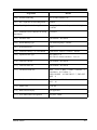
Table of Contents
1
1.1
1.2
1.3
1.4
1.5
1.6
2
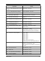
Programming Instructions ...............................................................9
Programming Instructions ..........................................................................................10
Using Proprietary Telephones .....................................................................................11
Programming Methods ................................................................................................15
Entering Characters.....................................................................................................17
User Programming Mode ............................................................................................22
Programming Example ................................................................................................23
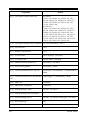
General Programming ....................................................................27
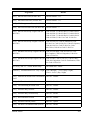
2.1 Manager Programming ...............................................................................................28
[000] Date and Time Set.......................................................................................................28
[001] System Speed Dialling Number Set ...........................................................................30
[002] System Speed Dialling Name Set ...............................................................................32
[003] Extension Number Set ................................................................................................34
[004] Extension Name Set....................................................................................................36
[005] Flexible CO Button Assignment.................................................................................38
[006] Operator / Manager Extension Assignment................................................................41
[007] Console Port and Paired Telephone Assignment........................................................43
[008] Absent Messages ........................................................................................................45
[009] Quick Dial Number Set ..............................................................................................47
[014] VM Name Set .............................................................................................................48
[015] Budget Management...................................................................................................49
[017] DISA / TIE User Codes ..............................................................................................51
2.2 System Programming...................................................................................................53
[100] Flexible Numbering ....................................................................................................53
[101] Day / Night Service Switching Mode.........................................................................57
[102] Day / Night Service Starting Time .............................................................................58
[103] Automatic Access Outside Line Group Assignment ..................................................60
[105] Account Codes............................................................................................................61
[106] Station Hunting Type ..................................................................................................63
[107] System Password ........................................................................................................65
[108] Automatic Hold by CO / DSS Button ........................................................................66
[109] Expansion Unit Type ..................................................................................................67
[110] Caller ID Code Set......................................................................................................70
[111] Caller ID Name Set.....................................................................................................72
[113] VM Status DTMF Set.................................................................................................73
[114] VM Command DTMF Set ..........................................................................................75
[115] Adjust Time ................................................................................................................77
[116] ROM Version Display.................................................................................................78
[117] Voice Mail Number Assignment.................................................................................79
[118] Voice Mail Extension Number Set..............................................................................81
[119] Voice Mail Extension Group Assignment ..................................................................83
[120] User Password ............................................................................................................85
[121] Walking COS Password..............................................................................................86
[122] UCD Overflow............................................................................................................87
[123] UCD Time Table.........................................................................................................89
Table of Contents
3
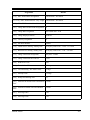
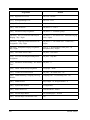
[124] Phantom Extension Number Set ................................................................................ 91
[125] Area Code Assignment .............................................................................................. 93
[126] Caller ID Modification for Local Call ....................................................................... 95
[127] Caller ID Modification for Long Distance Call ......................................................... 97
[128] PBX Code .................................................................................................................. 98
[129] E&M Signal Assignment ........................................................................................... 99
[130] Message Waiting Control......................................................................................... 100
[131] Message Waiting Lamp Assignment........................................................................ 102
[132] Message Waiting Port Set ........................................................................................ 104
[134] Hotel Application..................................................................................................... 106
[135] DID Number Conversion Selection ......................................................................... 107
[136] DID / DDI Number Assignment .............................................................................. 108
[137-138] DID / DDI Extension – Day / Night ................................................................. 110
[139] DID / DDI Extension Name Set .............................................................................. 112
[141] Charge Rate Decimal Point Assignment.................................................................. 114
[142] Charge Rate Assignment.......................................................................................... 115
[143] Charge Display Selection......................................................................................... 117
[144] Currency Assignment............................................................................................... 118
[148] Off-Hook Monitor.................................................................................................... 119
[150] Lunch Service Starting / Ending Time..................................................................... 120
[151] Break Service Starting / Ending Time ..................................................................... 122
[152] Charge Verification Assignment .............................................................................. 124
[153] Charge Verification ID Code Set ............................................................................. 125
2.3 Timer Programming.................................................................................................. 126
[200] Hold Recall Time ..................................................................................................... 126
[201] Transfer Recall Time................................................................................................ 127
[202] Call Forwarding – No Answer Time........................................................................ 128
[203] Intercept Time .......................................................................................................... 129
[204] Pickup Dial Waiting Time........................................................................................ 130
[205] Extension-to-Outside Line Call Duration Time....................................................... 131
[206] Outside-to-Outside Line Call Duration Time .......................................................... 132
[207] First Digit Time........................................................................................................ 133
[208] Inter Digit Time ....................................................................................................... 134
[209] Automatic Redial Repeat Times .............................................................................. 135
[210] Automatic Redial Interval Time............................................................................... 136
[211] Dial Start Time......................................................................................................... 137
[212] Call Duration Count Start Time ............................................................................... 138
[213] DISA Delayed Answer Time ................................................................................... 139
[214] DISA Prolong Time ................................................................................................. 140
[215] Outgoing Message Time .......................................................................................... 141
[216] Message Waiting Ring Interval Time....................................................................... 142
[217] Timed Reminder Alarm Ring Time ......................................................................... 143
[218] DISA AA Wait Time................................................................................................ 144
[219] Call Park Recall Time .............................................................................................. 145
[220] TIE First / Inter Digit Time...................................................................................... 146
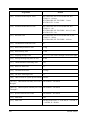
2.4 TRS / ARS Programming ......................................................................................... 147
[300] TRS Override for System Speed Dialling................................................................ 147
[301-305] TRS Denied Code Entry for Levels 2 through 6 .............................................. 148
[306-310] TRS Excepted Code Entry for Levels 2 through 6 ........................................... 150
4
Table of Contents
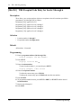
[311] Special Carrier Access Codes...................................................................................152
[312] ARS Mode ................................................................................................................153
[313] ARS Time .................................................................................................................154
[314-321] ARS Leading Digit Entry for Plans 1 through 8 ...............................................156
[322-329] ARS Routing Plans 1 through 8 ........................................................................158
[330] ARS Modify Removed Digit ....................................................................................160
[331] ARS Modify Added Number....................................................................................161
[332] Extra Entry Table Selection ......................................................................................162
[333] TRS Entry Code Assignment for Extra Table ..........................................................163
[334] Emergency Dial Number Set ....................................................................................164
[340] TIE Line Routing Table ............................................................................................165
[341] TIE Modify Removed Digit / Added Number..........................................................167
2.5 Outside Line Programming .......................................................................................169
[400] Outside Line Connection Assignment ......................................................................169
[401] Outside Line Group Assignment ..............................................................................171
[402] Dial Mode Selection .................................................................................................173
[403] Pulse Speed Selection ...............................................................................................175
[404] DTMF Time ..............................................................................................................177
[405] CPC Signal Detection Incoming Set ........................................................................179
[406] Caller ID Assignment ...............................................................................................181
[407-408] DIL 1:1 Extension – Day / Night ......................................................................183
[409-410] Intercept Extension – Day / Night.....................................................................185
[411] Host PBX Access Codes...........................................................................................187
[412] Pause Time................................................................................................................189
[413] Flash Time ................................................................................................................190
[414] Disconnect Time .......................................................................................................192
[415] CPC Signal Detection Outgoing Set.........................................................................193
[416] Reverse Circuit Assignment .....................................................................................195
[417] Outside Line Name Assignment...............................................................................196
[430] DID / TIE Format Number Assignment ...................................................................198
[431] DID / TIE Incoming Assignment .............................................................................199
[432] DID / TIE Outgoing Assignment..............................................................................201
[433] DID / TIE Subscriber Number Removed Digit ........................................................203
[434] DID / TIE Added Number ........................................................................................204
[435] DID / TIE Wink Time Out Assignment....................................................................205
[436] Outside-to-TIE Transfer ...........................................................................................207
[437] TIE-to-Outside Transfer ...........................................................................................208
[438] TIE-to-TIE Transfer..................................................................................................209
[439] TIE Security Type.....................................................................................................210
[440] Line Hunting Sequence ............................................................................................211
[441] Voice Path Type ........................................................................................................212
[442] Voice Level (Transmit) .............................................................................................213
[443] Voice Level (Receive) ...............................................................................................214
[444] TIE Receive Dial ......................................................................................................215
[445] DID Forward Timer (for MFC-R2) ..........................................................................216
[446] DID Backward Timer (for MFC-R2)........................................................................217
[447] DID Disappearance Timer (for MFC-R2) ................................................................218
[448] DID First Dial Start Time (for MFC-R2) .................................................................219
[449] DID Forward Group-I Signal Code (for MFC-R2) ..................................................220
Table of Contents
5
[450] DID Forward Group-II Signal Code (for MFC-R2) ................................................ 221
[451] DID Backward Group-A Signal Code (for MFC-R2) ............................................. 222
[452] DID Backward Group-B Signal Code (for MFC-R2).............................................. 223
[457-458] DIL 1:1 – Lunch / Break Group ....................................................................... 224
2.6 COS Programming .................................................................................................... 226
[500-501] Toll Restriction Level – Day / Night ................................................................ 226
[502] Extension-to-Outside Line Call Duration Limit ...................................................... 228
[503] Call Transfer to Outside Line................................................................................... 230
[504] Call Forwarding to Outside Line ............................................................................. 231
[505] Executive Busy Override ......................................................................................... 232
[506] Executive Busy Override Deny................................................................................ 233
[507] Do Not Disturb Override ......................................................................................... 234
[508] Account Code Entry Mode ...................................................................................... 235
[509] Off-Hook Call Announcement (OHCA).................................................................. 237
[510] Night Service Access ............................................................................................... 238
[511] PT Programming Level............................................................................................ 239
2.7 Extension Programming ........................................................................................... 241
[600] EXtra Device Port .................................................................................................... 241
[601] Class of Service ....................................................................................................... 243
[602] Extension Group Assignment .................................................................................. 245
[603-604] DIL 1:N Extension and Delayed Ringing – Day / Night.................................. 247
[605-606] Outgoing Permitted Outside Line Assignment – Day / Night.......................... 249
[607-608] Doorphone Ringing Assignment – Day / Night ............................................... 251
[609] Voice Mail Access Codes......................................................................................... 253
[610] Live Call Screening Recording Mode Assignment.................................................. 255
[619] Extension Call Forwarding – No Answer Time....................................................... 257
[620] Lunch / Break Group Assignment ........................................................................... 259
[621] Cordless PT Extension Port ..................................................................................... 260
2.8 Resource Programming............................................................................................. 262
[800] SMDR Incoming / Outgoing Call Log Printout....................................................... 262
[801] SMDR Format.......................................................................................................... 264
[802] System Data Printout ............................................................................................... 265
[803] Music Source Use .................................................................................................... 267
[804] External Pager BGM................................................................................................ 269
[805] External Pager Confirmation Tone........................................................................... 271
[806-807] Serial Interface (RS-232C) Parameters ............................................................ 272
[809] DISA Security Type ................................................................................................. 274
[810] DISA Tone Detection............................................................................................... 275
[812] DISA DTMF Repeat ................................................................................................ 276
[813] Floating Number Assignment .................................................................................. 277
[814] Modem Standard...................................................................................................... 279
[815] DISA Built-in Automated Attendant Number ......................................................... 280
[816] SMDR Output Mode................................................................................................ 281
[817] KX-TD197 / KX-TD198 Baud Rate Set.................................................................. 282
3
ISDN Programming ...................................................................... 283
3.1 Manager Programming............................................................................................. 284
[012] ISDN Extension Number Set ................................................................................... 284
[013] ISDN Extension Name Set ...................................................................................... 286
6
Table of Contents
[018] Budget Management for ISDN Extension................................................................288
3.2 System Programming.................................................................................................290
[109] Expansion Unit Type ................................................................................................290
[112] ISDN Network Type Assignment .............................................................................293
[140] DDI Number / Phantom Extension Number Conversion .........................................294
[149] ISDN Data Assignment ............................................................................................295
[154] DID Transfer Table for DDI Call..............................................................................298
3.3 ISDN Line Programming...........................................................................................299
[418] Outside Line Number Assignment for ISDN / E1....................................................299
[419] ISDN Outgoing CLIR Service Assignment..............................................................301
[420] ISDN Ring Service Assignment ...............................................................................303
[421] DDI Removed Digit / Added Number Assignment..................................................305
[423] ISDN Port Type ........................................................................................................307
[424] ISDN Layer 1 Active Mode......................................................................................309
[425] ISDN Configuration..................................................................................................311
[426] ISDN Data Link Mode .............................................................................................313
[427] ISDN TEI Mode .......................................................................................................315
[428] ISDN Extension Multiple Subscriber Number .........................................................317
[429] ISDN Extension Progress Tone ................................................................................319
[454] MSN Assignment .....................................................................................................321
[455-456] Extension Ringing Assignment – Day / Night for ISDN ..................................323
[460] PRI Configuration.....................................................................................................325
[721] PRI / E1 Reference CO.............................................................................................326
3.4 Extension Programming ............................................................................................328
[611] DDI Number / Extension Number Conversion.........................................................328
[612] DDI Number / Floating Number Conversion ...........................................................330
[613] ISDN Class of Service ..............................................................................................331
[614-615] Outgoing Permitted Outside Line Assignment – Day / Night for ISDN Extension ...333
[616] DDI Number / ISDN Extension Number Conversion ..............................................335
[617] CLIP / COLP Number Assignment for Extension ...................................................337
[618] CLIP / COLP Number Assignment for ISDN Extension .........................................339
4
E1 Programming ...........................................................................341
4.1 System Programming.................................................................................................342
[109] Expansion Unit Type ................................................................................................342
4.2 E1 Outside Line Programming .................................................................................345
[418] Outside Line Number Assignment for ISDN / E1....................................................299
4.3 Extension Programming ............................................................................................347
[622] Extension ANI Number ............................................................................................347
4.4 E1 Line Programming................................................................................................349
[707] E1 Clock Mode .........................................................................................................349
[720] E1 TIE Ringing Service............................................................................................350
[721] PRI / E1 Reference CO.............................................................................................326
[722] E1 Answer Wait Timer .............................................................................................353
[723] E1 Sending TIE Caller ID ........................................................................................354
[740] E1 Channel Assignment ...........................................................................................356
[741] E1 Dial Mode............................................................................................................357
[742] E1 CPC (IN) .............................................................................................................359
[743] E1 CPC (OUT) .........................................................................................................360
Table of Contents
7
[744]
[745]
[747]
[748]
[749]
[750]
[751]
[752]
[753]
[754]
[755]
[756]
[757]
[758]
[759]
[760]
[761]
[762]
[763]
[764]
[765]
[766]
[767]
[768]
[769]
[770]
[771]
[772]
[773]
[774]
[775]
[776]
[777]
[778]
[779]
[780]
[781]
[782]
[783]
[784]
[785]
5
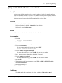
E1 DID Receive Digit .............................................................................................. 361
E1 DR2 Receiver ..................................................................................................... 362
E1 Line Coding ........................................................................................................ 363
E1 Frame Sequence ................................................................................................. 364
E1 Frame Option...................................................................................................... 365
E1 First Dial Timer (DR2 / TIE).............................................................................. 366
E1 %Break ............................................................................................................... 367
E1 Dial Click Tone................................................................................................... 368
E1 Inter Digit Pause ................................................................................................. 369
E1 Flash Detection................................................................................................... 370
E1 Answer Decision Timer...................................................................................... 371
E1 Seizure ACK Wait Timer.................................................................................... 372
E1 Pulse Type........................................................................................................... 373
E1 DR2 Signalling Type .......................................................................................... 374
E1 Inter Digit Timer................................................................................................. 375
E1 Bit Position for Dial Pulse.................................................................................. 376
E1 Bit Position for Clear Back ................................................................................ 377
E1 E&M Signalling Type......................................................................................... 378
E1 E&M Pulse Length (Seizure) ............................................................................. 379
E1 E&M Pulse Length (Answer)............................................................................. 380
E1 E&M Pulse Length (Clear)................................................................................. 381
E1 Meter Pulse Detection Mode .............................................................................. 382
E1 Meter Pulse Detection Bit Position .................................................................... 383
E1 Meter Pulse Detection Length ............................................................................ 384
E1 DSP Gain (DTMF Transmit).............................................................................. 385
E1 DSP Gain (DTMF Receive) ............................................................................... 386
E1 DSP Gain (MFC-R2 Transmit)........................................................................... 387
E1 DSP Gain (MFC-R2 Receive) ............................................................................ 388
E1 Frame Error Detection........................................................................................ 389
E1 Error Rate ........................................................................................................... 390
E1 ANI Service Mode.............................................................................................. 391
E1 ANI Maximum Digits ........................................................................................ 392
E1 MFC-R2 Forward Timer..................................................................................... 393
E1 MFC-R2 Backward Timer.................................................................................. 394
E1 MFC-R2 Disappearance Timer .......................................................................... 395
E1 Group-I ............................................................................................................... 396
E1 Group-II.............................................................................................................. 397
E1 Group-A.............................................................................................................. 398
E1 Group-B.............................................................................................................. 399
E1 Group-C.............................................................................................................. 400
E1 Tone Type for Making Calls ............................................................................... 401
Optional Programming ................................................................ 403
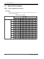
5.1 Optional Programming ............................................................................................. 404
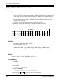
[990] System Additional Information ............................................................................... 404
[991] COS Additional Information ................................................................................... 418
8
6
Default Values................................................................................ 421
7
Index............................................................................................... 437
Table of Contents
Section 1
Programming Instructions
Programming Instructions
9
1.1
Programming Instructions
1.1
Programming Instructions
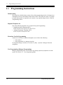
Default Setting
This system has a default factory setting. If any of the programming needs to be changed, you
will find the necessary information in the Features Guide. This makes the system very simple
to install and customise as required by the customer. Any required changes can be written in
"Programming Tables".
Required Telephone Set
One of the following telephone sets is required for System Programming:
• Digital Proprietary Telephone (DPT):
KX-T7436, KX-T7433, KX-T7235, KX-T7230
• Analogue Proprietary Telephone (APT):
KX-T7130, KX-T7030, KX-T7033
Extensions Used for Programming
Connect one of the above-mentioned telephone sets to either of the following:
• Jack number 1
• Jack programmed as a manager extension
To assign the manager extension, see Section 2.1 [006] Operator / Manager Extension
Assignment.
User Programming (Manager Programming)
Manager programming items are allowed for any display proprietary telephone user in the
system. See Section 1.5 User Programming Mode.
10
Programming Instructions
1.2
1.2
Using Proprietary Telephones
Using Proprietary Telephones
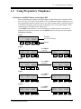
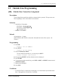
Soft Buttons and SHIFT Button on the Display DPT
Three soft buttons are provided just below the display of Digital Proprietary Telephones (DPT),
KX-T7433, KX-T7436, KX-T7230 and KX-T7235. The functions of these soft buttons vary as
the programming procedures advance step by step. Those functions that are currently assigned
to the buttons are shown on the lower line of the display. (See "Viewing the Display" in this
section for more information on the display lines.)
If the SHIFT button indicator is on, two functions are available with each soft button. To
alternate between the two functions, press the SHIFT button on the right side of the display.
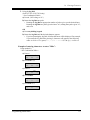
Soft button variations
Type 1
Example:
KX-T7230 Display
CLR
NEXT
Buttons
Soft 1
Type 2
Soft 2
Soft 3
SHIFT
Press SHIFT
to alternate
SKP+ CLR
NEXT
Soft 1
Soft 3
Soft 2
SKP-
SHIFT
PREV
Soft 1
Soft 2
<-
SEL-
Soft 3
SHIFT
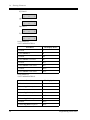
Type 3
Press SHIFT
to alternate
->
Soft 1
SEL+
Soft 2
NEXT
Soft 3
SHIFT
Soft 1
Soft 2
a
b
PREV
Soft 3
SHIFT
Type 4
Press SHIFT
to alternate
A
Soft 1
B
Soft 2
C
Soft 3
SHIFT
Soft 1
Soft 2
c
Soft 3
SHIFT
Type 5
Press SHIFT
to alternate
SKP+ SEL
NEXT
Soft 1
Soft 3
Soft 2
Programming Instructions
SHIFT
SKP- CLR
Soft 1
Soft 2
PREV
Soft 3
SHIFT
11
1.2
Using Proprietary Telephones
You can use either the soft buttons or the overlay buttons. (For overlay buttons, refer to "Using
the Overlay" below.)
Throughout programming you will see instructions such as "Press PREV". If you use soft
buttons, this means press SHIFT, release SHIFT and then press Soft 3. The (PREV) function
is performed.
Note
If you use soft buttons and if programming instructions tell you to press the following buttons,
you may press soft buttons shown below.
Instructions
Soft button
SELECT
SEL+, SEL-, or SEL
CLEAR
CLR
Using the Overlay
A programming overlay is packed with the telephone at the factory. This overlay should be
used at all times while in programming mode since the functions of the telephone keys change
while in programming mode as follows: (The original functions are in parentheses.)
During Normal Operation
During Programming
(PAUSE)
PAUSE / PROGRAM
(SP-PHONE)
NEXT
(REDIAL)
PREV (PREVIOUS)
(AUTO ANSWER / MUTE)
SELECT
(FLASH)
FLASH
(TRANSFER)
CLEAR
(FWD/DND)
(CONF)
12
—/
(INTERCOM)
SECRET
(AUTO DIAL / STORE)
STORE
(HOLD)
END
Programming Instructions
1.2
Using Proprietary Telephones
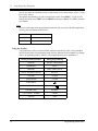
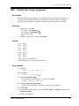
Location of Controls with the Overlay
The pictures below show the functions of the buttons of the proprietary telephone while in
programming mode. There are Overlays for the KX-T7400 and KX-T7200 series telephones.
KX-T7436 and KX-T7230 are used for the examples.
KX-T 7436
SHIFT
SECRET
PROGRAM
PAUSE
CLEAR
PAUSE
SECRET
1QZ!?
2ABC
3DEF
STORE
4GHI
5JKL
6MNO
FLASH
1QZ!?
SELECT
2ABC
CLEAR
3DEF
1
2
3
4GHI
5JKL
6MNO
4
5
6
8TUV
9WXY
7PQRS
8TUV
9WXYZ
7PRS
7
8
9
/+–=<>
0.,’:;
#$%&@( )
/+–=<>
0.,’:;
#$%&@( )
PREV
END
NEXT
STORE
SELECT
0
PREV
FLASH
END
NEXT
KX-T7230
KX-T7436
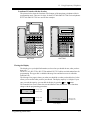
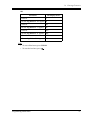
Viewing the Display
The display gives you helpful information, such as what you should do now, what you have
done, etc.
The KX-T7433, KX-T7436, KX-T7230 and the KX-T7235 utilise two information lines for
programming. The upper line is called the Message Line and the lower one is called the
Function Line.
The Message Line (upper) shows you what you should do or what you should select. It also
allows you to confirm what you have just entered. The display capacity is 16 digits. If your
entry exceeds the capacity, you can shift the display by pressing
or
button.
The Function Line (lower) shows the current function of the soft buttons. These functions
change with the programming procedures.
SYS-PGM NO? →
CLR
NEXT
← Message Line
← Function Line
2-Line Display
SYS-PGM NO? →
CLR
NEXT
3-Line Display
Programming Instructions
← Message Line
← Function Line
SYS-PGM NO? →
CLR
NEXT
← Message Line
← Function Line
6-Line Display
13
1.2
Using Proprietary Telephones
Before entering the programming mode
Before entering programming mode, confirm that:
• Your telephone is on-hook.
• No calls are on hold at your telephone.
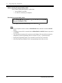
Entering the programming mode
Press PROGRAM (or PAUSE) +
Password (default=1234).
+ # and enter your System
• The display shows the Initial Message: SYG-PGM NO?
Note
• If your telephone set does not have a PROGRAM button, substitute it with the PAUSE
button.
• If nothing is entered in five seconds after the PROGRAM (or PAUSE) button is pressed, it
is cancelled.
• The System Password entered is not shown on the display. The System Password can be
changed by System Programming. Refer to Section 2.2 [107] System Password.
• During the programming mode, your extension is treated as a busy extension.
• Only one proprietary telephone can be in programming mode at any one time.
14
Programming Instructions
1.3
1.3
Programming Methods
Programming Methods
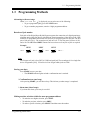
Advancing to the next stage
When "SYS-PGM NO? " is displayed, you can select one of the following:
• To go to programme [000], press the NEXT button.
• To go to another programme, enter the 3-digit programme address.
Rotation of jack number
Each jack of the Digital Super Hybrid System supports the connection of a digital proprietary
telephone and a single line device with different extension numbers (eXtra Device Port: XDP
function). To programme this function it is necessary to assign two parts for each jack. The first
part of jack one is 01-1. The second part of jack one is 01-2. The first part of jack two is 02-1
and so on. The NEXT and PREV buttons can be used to move from jack to jack as required.
Example
NEXT
#01-1
NEXT
#01-2
PREV
NEXT
#02-1
PREV
#02-2......
PREV
Note
The first part of a jack is for a DPT of a XDP-assigned jack. The second part is for a single line
device. Programme [600] EXtra Device Port assigns which jacks are XDP.
Storing your data
Press STORE to store your data.
• The STORE indicator lights red and a confirmation tone is emitted.
* Confirmation tone (one beep)
After pressing STORE, you will hear a beep. This informs you that storage is completed.
* Alarm tone (three beeps)
If you hear this alarm, your entry is not valid.
Making another selection within the same programme address
• To make the next higher selection, press NEXT.
• To make the previous selection, press PREV.
• To make a specific selection, press SELECT and then enter the number.
Programming Instructions
15
1.3
Programming Methods
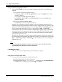
Going to another programme address
After pressing STORE, you can go to another programme with either of the following two
methods:
a) To go to the next larger programme address:
Press Soft 1 (SKP+) or VOLUME (DOWN) or rotate the Jog Dial in the counterclockwise direction.
To go to the next smaller programme address:
Press SHIFT + Soft 1 (SKP–) or VOLUME (UP) or rotate the Jog Dial in the
clockwise direction.
b) To go to a specific programme address:
Press END, then enter the programme Address.
Method (1) is useful when you want to perform a series of programmes consecutively. For
example, to change the programming in addresses [0XX], use this method. You can move from
[000] to [001], from [001] to [002], and so on by pressing the SKP+ or VOLUME . You can
move in reverse order from [008] to [007], etc. by pressing the SKP– or VOLUME .
This method can also be used to move between neighboring programme groups: For example,
you can move between the programme addresses of the largest [0XX] and [100], the largest
[1XX] and [200], and so on. Also, you can move between the smallest programme address
[000] and the largest one [9XX].
Method (2) is useful when you wish to jump to another programme address. For example, you
have just finished with programme [006] and now you want to go to programme [301]. Neither
SKP+ / VOLUME nor SKP–/VOLUME is convenient in this case. So you should press
END and enter 301.
Note
The following programming instructions assume that you have already entered the
programming mode and that you will use Method (b).
Confirming the entries
You may review the stored programming without making any changes.
Going back to the operation mode
Two ways are available to go back to the operation mode:
a) Lift the handset while in programming mode.
b) When the Initial Message: SYS-PGM NO? is displayed, press the PROGRAM (or
PAUSE) button. (To display the Initial Message, press END.)
16
Programming Instructions
1.4
1.4
Entering Characters
Entering Characters
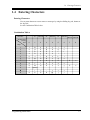
Entering Characters
You can enter characters to store names or messages by using the dialling key pad, buttons or
the Jog Dial.
See the Combination Tables below.
Combination Table a
Soft button
S1
SHIFT+S1
S2
SHIFT+S2
S3
SHIFT+S3
0
1
2
3
4
5
6
1
1
Q
q
Z
z
!
?
2
2
A
a
B
b
C
c
3
3
D
d
E
e
F
f
4
4
G
g
H
h
I
i
5
5
J
j
K
k
L
l
6
6
M
m
N
n
O
o
7
7
P
p
Q
q
R
8
8
T
t
U
u
V
9
9
W
w
X
x
0
0
(space)
.
,
*
/
+
#
#
$
%
SELECT button
pressing
times
SHIFT+
SHIFT+
SHIFT+S1 SHIFT+S2
7
8
r
S
s
Y
v
y
Z
z
’
:
;
-
=
<
>
&
@
(
)
keys
Programming Instructions
17
1.4
Entering Characters
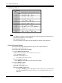
Combination Table b
Jog Dial
keys
Display sequence by rotating the Jog Dial
1
1 Q q R r S s T t ···
2
2 A a B b C c D d ···
3
3 D d E e F f G g ···
4
4 G g H h I i J j ···
5
5 J j K k L l M m ···
6
6 M m N n O o P p ···
7
7 P p Q q R r S s ···
8
8 T t U u V v W w ···
9
9 W w X x Y y Z z (space) ···
0
0 (space) ! ? . , ’ : ; ···
* / + – = < > # $ ···
#
# $ % & @ ( ) A a B b ···
Note
• The alphabetical characters correspond to the letters shown on the twelve dialling keys on
the proprietary telephone. (except symbols)
• In Combination Table b:
If you keep rotating the Jog Dial, all of the characters in the table will be displayed.
Character Entering Methods
Please see the following example which shows how to select a desired character.
For example, to select the letter "M":
Select either of the following three methods:
1. Using the SHIFT and Soft buttons
(for KX-T7433 / KX-T7436 / KX-T7230 / KX-T7235 only)
* See Combination Table a.
a) Press 6. ("M" belongs to "6".)
• The Function Line shows: M N O
b) Press the Soft 1 (M) button.
(Press SHIFT to display the lower case of the above letters.)
2. Using the SELECT button
* See Combination Table a.
a) Press 6. ("M" belongs to "6".)
b) Press the SELECT button once.
• Pressing the SELECT button an appropriate number of times gives you the desired
letter. Pressing SELECT twice gives the letter "m", pressing three times gives "N",
and so on.
18
Programming Instructions
1.4
Entering Characters
3. Using the Jog Dial
(for KX-T7433 / KX-T7436 only)
* See Combination Table b.
a) Press 6. ("M" belongs to "6".)
b) Rotate the Jog Dial one pulse.
• Rotating the Jog Dial an appropriate number of pulses gives you the desired letter.
Rotating the Jog Dial two pulses gives the letter "m", rotating three pulses gives "N",
and so on.
OR
a) Press any dialling keypad.
b) Rotate the Jog Dial until the desired character appears.
• If you keep rotating the Jog Dial, all of the characters will be displayed. For example,
if you rotate the Jog Dial after pressing 2, characters will appear in the following
order: A a B b •••• Z z (space) ! ? . , ' : ; * / + — = < > # $ % & @ ( ) A a B b ••••
Example of entering characters: to enter "Mike":
Using method (1)
* See Combination Table a.
a) Enter 6.
6
M
N
O
b) Press Soft 1 (M).
M
M
N
O
c) Enter 4.
M4
G
H
I
d) Press SHIFT.
M4
g
h
i
e) Press Soft 3 (i).
Mi
g
Programming Instructions
h
i
19
1.4
Entering Characters
f) Enter 5.
Mi5
j
k
l
g) Press Soft 2 (k).
Mik
j
k
l
h) Enter 3.
d
Mik3
e
f
i) Press Soft 2 (e).
d
Mike
e
f
Using method (2)
* See Combination Table a.
Procedures
The display shows:
1. Enter 6.
6
2. Press SELECT.
M
3. Enter 4.
M4
4. Press SELECT six times.
Mi
5. Enter 5.
Mi5
6. Press SELECT four times.
Mik
7. Enter 3.
Mik3
8. Press SELECT four times.
Mike
Using method (3)
* See Combination Table b.
Procedures
20
The display shows:
1. Enter 6.
6
2. Rotate Jog Dial one pulse.
M
3. Enter 4.
M4
4. Rotate Jog Dial six pulse.
Mi
5. Enter 5.
Mi5
6. Rotate Jog Dial four pulses.
Mik
7. Enter 3.
Mik3
8. Rotate Jog Dial four pulses.
Mike
Programming Instructions
1.4
Entering Characters
OR
Procedures
The display shows:
1. Enter 2.
2
2. Rotate Jog Dial until "M" appears. M
3. Enter 2.
M2
4. Rotate Jog Dial until "i" appears.
Mi
5. Enter 2.
Mi2
6. Rotate Jog Dial until "k" appears. Mik
7. Enter 2.
Mik2
8. Rotate Jog Dial until "e" appears. Mike
Note
• To erase all the letters, press CLEAR.
• To erase the last letter, press
Programming Instructions
.
21
1.5
User Programming
1.5
User Programming Mode
User Programming Mode
Manager programming items (programme address: [0XX]) are accessible by any display
proprietary telephone user in the system.
Entering the user programming mode
You can access these programmes by entering the User Programming Mode as follows:
Before entering the mode, confirm that:
• Your telephone is on-hook.
• No calls are on hold at your telephone
Press PROGRAM (or PAUSE) +
Password (default=1234)
+
and enter the User
After entering the mode, perform the same programming steps as the system programming
steps in each programme address.
Note
• If your telephone set does not have a PROGRAM button, substitute it with the PAUSE
button.
• If nothing is entered in five seconds after the PROGRAM (or PAUSE) button is pressed, it
is cancelled.
• The User Password is not shown on the display. The password can be changed by system
programming. Refer to Section 2.2 [120] User Password.
• During the programming mode, your extension is treated as a busy extension.
• Only one proprietary telephone can be in programming mode at any one time.
22
Programming Instructions
1.6
1.6
Programming Example
Programming Example
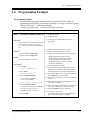
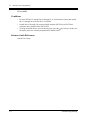
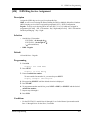
Programming Example
The following programming instructions assume that you have already entered the
programming mode and that you will employ method (b) of "Going to another programme
address" in Section 1.3 Programming Methods.
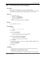
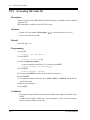
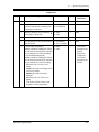
Example: programme [001] System Speed Dialling Number Set
Sample of Description
Explanation
(2)
[001] (1) System Speed Dialling Number Set
(1) Programme address.
(2) Programme title.
Description (3)
(3) Provides a more detailed description of the
programme.
Used to program the System Speed Dial numbers.
These numbers are available to all extension
users. There are 500 numbers from 000 through
499.
Selection
(4) Shows you choices that you can assign.
(5) Shows you the default (factory setting).
(6) Shows you programming procedures step by step.
• While programming, use the overlay.
• Before starting to programme, enter the
programming mode. (See Entering the
programming mode in Section 1.2 Using
Proprietary Telephones.)
(7) Enter the programme address.
(8) The display shows the programme title. If your
telephone has soft buttons, the lower line shows
the functions that are currently assigned to them.
(9) Press either Soft 3 (NEXT)shown on the display
or the NEXT shown on the overlay.
(4)
• Speed dial number: 000 through 499
• Telephone number: 24 digits (max.)
Default
(5)
All speed dial numbers – Not stored
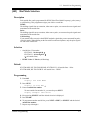
Programming
(6)
(7)
1. Enter 001.
Display: SPD Number Set
2. Press NEXT.
(8)
(9)
Display: SPD Code?→
(10)
3. Enter a speed dial number.
To enter speed dial number 000,
you can also press NEXT.
Display example: 000:Not Stored
(11)
4. Enter a telephone number. (12)
To delete the current entry, press CLEAR.
To change the current entry, press
CLEAR and enter the new number.
5. Press STORE.
(14)
Programming Instructions
(13)
(10) The message line advises you to enter a speed dial
number.
(11) If the telephone number has already been stored,
the number is displayed.
(12) Enter the telephone number that you want to store.
Your entry is displayed as you enter the digits.
(13) Pressing CLEAR erases the whole entry.
(14) Your entry is now stored.
The indicator lights red and a confirmation tone
lets you know that storage is completed.
23
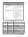
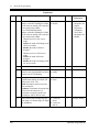
1.6
Programming Example
Sample of Description
Explanation
6. To programme another speed dial number,
press NEXT or PREV, or SELECT and
the desired speed dial number. (15)
7. Repeat steps 4 through 6. (16)
8. Press END. (17)
Conditions
(18)
• Each speed dial number has a maximum of 24
digits. The valid characters are 0 through 9,
and # keys, FLASH, PAUSE, SECRET
and – (hyphen) buttons.
•
•
•
•
•
•
•
•
Features Guide References
(15) Select the best way for you to store another speed
dial number. Pressing the NEXT / PREV allows
you to select the next higher / lower speed dial
number. You can also keep pressing them until the
desired one is displayed. If you press SELECT
and the desired speed dial number, the selected
code is displayed.
(16) You can continue to programme another entry.
(17) After you have stored all your entries, finish this
programme by pressing END. After pressing END
you can go to any programme address you desire.
You can return to the Initial Message mode any
time by pressing END.
To go to the next larger programme address, do not
press END but press Soft 1 (SKP+) or
VOLUME or rorate the Jog Dial in the
counter-clockwise direction.
To go to the next smaller programme address, do
not press END but press SHIFT + Soft 1 (SKP-)
or VOLUME or rorate the Jog Dial in the
counter-clockwise direction.
(18) Tells you what you should notice or consider when
doing the programming.
(19) Lists all of the features related to the
programming. These features are described in
the Features Guide.
(19)
System Speed Dialling
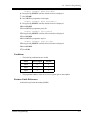
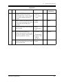
Programming Structure
Programme
Address
24
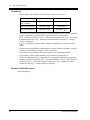
Programming Group
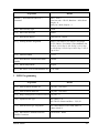
Description
[0XX]
Manager Programming
These programmes may be accessed by the system
manager of the customer to meet frequent changes
requested by the customer.
[1XX]
System Programming
Entire system programming.
[2XX]
Timer Programming
Flexible system timer setting.
[3XX]
TRS / ARS / TIE Line
Assignment of Toll Restriction, Automatic Route
Routing Table Programming Selection (ARS) or TIE Line Routing Table.
[4XX]
Outside Line / ISDN Line /
TIE Line Programming
Setting of outside line, outside line group, ISDN line
or TIE line values.
[5XX]
COS Programming
Setting of Class of Service (COS).
[6XX]
Extension Programming
Setting of extension values.
[7XX]
E1 Line Programming
Setting of E1 line values.
Programming Instructions
1.6
Programming Example
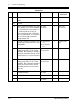
Programming Structure
Programme
Address
Programming Group
Description
[8XX]
Resource Programming
Assignment of customer-supplied peripherals
connected to the system.
[9XX]
Optional Programming
Used to answer the user's requirements or troubles,
if needed.
Programming Instructions
25
1.6
26
Programming Example
Programming Instructions
Section 2
General Programming
General Programming
27
2.1
Manager Programming
2.1
Manager Programming
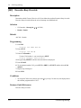
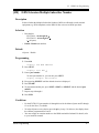
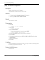
[000] Date and Time Set
Description
Sets the current date and time. A 12 hour clock or 24 hour clock can be selected.
Selection
•
•
•
•
•
•
•
•
Year: 00 through 99
Month: Jan. through Dec.
Day: 1 through 31
Day of the week: SUN / MON / TUE / WED / THU / FRI / SAT
Hour: 1 through 12
Minute: 00 through 59
AM / PM
Clock hour: 12 or 24
Default
'93 Jan. 1 FRI 12:00 AM 12
Programming
1. Enter 000.
Display: 000 DATE / TIME
2. Press NEXT.
Display example: '93 Jan. 1 FRI
3. Enter the year.
To change the current entry, press CLEAR and enter the new year.
.
4. Press
5. Keep pressing SELECT until the desired month is displayed.
.
6. Press
7. Enter the day.
To change the current entry, press CLEAR and enter the new day.
.
8. Press
9. Keep pressing SELECT until the desired day of the week is displayed.
10.Press STORE.
11.Press NEXT.
Display example: 12:00 PM 24
28
General Programming
2.1
Manager Programming
12.Enter the hour.
To change the current entry, press CLEAR and enter the new hour.
.
13.Press
14.Enter the minute.
To change the current entry, press CLEAR and enter the new minute.
.
15.Press
16.Press SELECT for AM or PM.
.
17.Press
18.Press SELECT for 12 or 24 (clock hour).
19.Press STORE.
20.Press END.
Conditions
• After changing an entry, you can press STORE. You do not have to perform the rest of the
steps.
•
•
•
•
To return to a previous field, press
in steps 4 through 9 and steps 13 through 18.
If you hear an alarm after pressing STORE, check that the date is valid.
The clock starts immediately after the STORE button is pressed.
You cannot leave an entry empty.
Features Guide References
Display Message
General Programming
29
2.1
Manager Programming
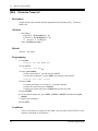
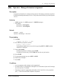
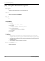
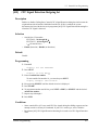
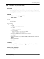
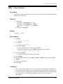
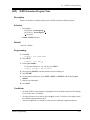
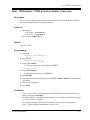
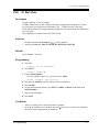
[001] System Speed Dialling Number Set
Description
Used to programme the System Speed Dial numbers. These numbers are available to all
extension users. There are 500 numbers available from 000 to 499.
Selection
• Speed dial number: 000 through 499
• Telephone number: 24 digits (max.)
Default
All speed dial numbers – Not stored
Programming
1. Enter 001.
Display: 001 SYS SPD DIAL
2. Press NEXT.
Display: SPD Code?
3. Enter a speed dial number.
To enter speed dial number 000, you can also press NEXT.
Display example: 000:Not Stored
4. Enter a telephone number.
To delete the current entry, press CLEAR.
To change the current entry, press CLEAR and enter the new number.
5. Press STORE.
6. To programme another speed dial number, press NEXT or PREV, or SELECT and the
desired speed dial number.
7. Repeat steps 4 through 6.
8. Press END.
30
General Programming
2.1
Manager Programming
Conditions
• Each speed dial number has a maximum of 24 digits. The valid characters are 0 through 9,
the and # keys, and the FLASH, PAUSE, SECRET and – (hyphen) buttons.
– To store a flash signal, press FLASH.
Note:
The stored flash will only be effective during a call. (Refer to External Feature Access
in the Features Guide.)
– To store a hyphen, press the "–" button.
– To store a pause, press PAUSE. (Refer to Pause Insertion, Automatic in the
Features Guide.)
– To store a feature number to convert pulse signals to DTMF (Dual Tone Multi-Frequency)
signals, press the and # keys.
(Refer to Pulse to Tone Conversion in the Features Guide.)
– To prevent displaying of all or part of the number, press SECRET before and after the
secret number. (Secret Dialling)
• If you are storing an external number, include the line access number (default: 9/0, 81
through 88) before the number. When dialling, a pause is automatically inserted after the
line access number.
• If you are storing an account code, enter the account code before the line access number.
(Refer to Account Code Entry in the Features Guide.)
• If you are storing a number for Incoming Outside Call Information Display with name,
enter "–" (hyphen) after the line access number. The system starts to compare the calling
party's number or called party's number with the System Speed Dialling number stored after
"–".
Example: 9 – 12345678
(Refer to Incoming Outside Call Information Display in the Features Guide.)
• A number consisting of 25 digits or more can be stored by storing it in two speed dial
numbers. The line access number should be stored in the first speed dial number.
• To access another speed dial number in step 6, press SELECT and start with step 3.
• To display parts of the number which have scrolled off the display, press
or
.
• Programme [002] System Speed Dialling Name Set is used to name the speed dial
numbers.
Features Guide References
Call Directory
System Speed Dialling
General Programming
31
2.1
Manager Programming
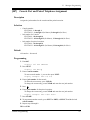
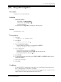
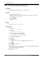
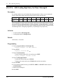
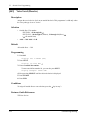
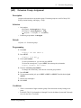
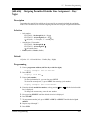
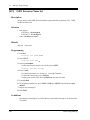
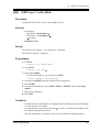
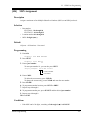
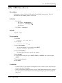
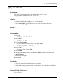
[002] System Speed Dialling Name Set
Description
Assigns names to the system speed dial numbers assigned in programme [001] System Speed
Dialling Number Set. KX-T7433, KX-T7436 and KX-T7235 telephones can show the stored
name during System Speed Dialling.
Selection
• Speed dial number: 000 through 499
• Name: 10 characters (max.)
Default
All speed dial numbers – Not stored
Programming
1. Enter 002.
Display: 002 SYS SPD NAME
2. Press NEXT.
Display: SPD Code?
3. Enter a speed dial number.
To enter speed dial number 000, you can also press NEXT.
Display example: 000:Not Stored
4. Enter a name.
For entering characters, see Section 1.4 Entering Characters.
To delete the current entry, press CLEAR.
To change the current entry, press CLEAR and enter the new name.
5. Press STORE.
6. To programme another speed dial number, press NEXT or PREV, or SELECT and the
desired speed dial number.
7. Repeat steps 4 through 6.
8. Press END.
Conditions
• Speed dial numbers are programmed in programme [001] System Speed Dialling Number
Set.
• To go to another speed dial number in step 6, press SELECT and start with step 3.
32
General Programming
2.1
Manager Programming
Features Guide References
Call Directory
System Speed Dialling
General Programming
33
2.1
Manager Programming
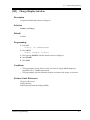
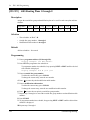
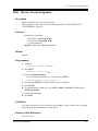
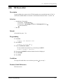
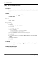
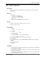
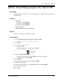
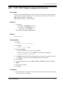
[003] Extension Number Set
Description
Assigns an extension number to each extension.
Selection
• Jack number:
KX-TD816 – 01 through 16 (-1 / -2)
KX-TD1232 – 01 through 64 (-1 / -2)
(-1 = first part, -2 = second part)
• Extension Number: 2 through 4 digits
Default
KX-TD816:
Jack 01-1 through 16-1 = 101 through 116;
Jack 01-2 through 16-2 = 201 through 216
KX-TD1232:
Jack 01-1 through 64-1 = 101 through 164;
Jack 01-2 through 64-2 = 201 through 264
Programming
1. Enter 003.
Display: 003 EXT NUMBER
2. Press NEXT.
Display: Jack NO?
3. Enter a jack number.
To enter jack number 01, you can also press NEXT.
To select the second part (-2), press NEXT after entering the jack number.
Display: #01-1:EXT101
4. Enter an extension number.
To change the current entry, press CLEAR and enter the new number.
5. Press STORE.
6. To programme another jack, press NEXT or PREV, or SELECT and the desired jack
number.
7. Repeat steps 4 through 6.
8. Press END.
34
General Programming
2.1
Manager Programming
Conditions
• There is a maximum of 32 extension numbers for KX-TD816, and 128 extension numbers
for KX-TD1232. Each extension number can be two, three, or four digits, consisting of 0
through 9. The and # keys cannot be used.
• For the KX-TD1232, jack numbers 01 through 32 are for the Master System and 33 through
64 are for the Slave, if available.
• An extension number is invalid if the first or second digits do not match with the programme
[100] Flexible Numbering, (01) - (16) 1st through 16th hundred extension blocks" setting.
If one digit is assigned as the leading digit, some extensions have two digits and some have
three digits. If two digits are assigned, some have three digits and some have four digits.
• Two extension numbers can be assigned per jack. If eXtra Device Port (XDP) is disabled
for the jack in programme [600] EXtra Device Port, the extension number of the second
part (XX-2) is not available. (XX=jack number)
• For an explanation of jack numbering, see "Rotation of jack number" in Section
1.3 Programming Methods.
• Double entry and incompatible entry for these numbers are invalid. Valid entry example: 10
and 11, 10 and 110. Invalid entry example: 10 and 106, 210 and 21.
To avoid making an invalid entry, check the other extension numbers. The default of each
extension number is as follows:
[012] ISDN Extension Number Set
Not stored.
[118] VM Extension Number Set
KX-TD816 – 165 through 170, 177, 178, 181 through 184
KX-TD1232 – 165 through 188
[124] Phantom Extension Number Set
Not stored.
[813] Floating Number Assignment
KX-TD816 – 191 through 194, 196, 198, 291 through 294, 298, 299
KX-TD1232 – 191 through 194, 196 through 198, 291 through 294, 296 through 299
• Programme [004] Extension Name Set is used to name the extension numbers.
Features Guide References
Call Directory
Display Message
EXtra Device Port (XDP)
Flexible Numbering
Intercom Calling
General Programming
35
2.1
Manager Programming
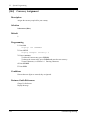
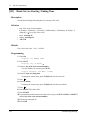
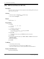
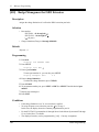
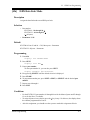
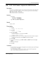
[004] Extension Name Set
Description
Assigns names to the extension numbers programmed in programme [003]
Number Set.
Extension
Selection
• Jack number:
KX-TD816 – 01 through 16 (-1 / -2)
KX-TD1232 – 01 through 64 (-1 / -2)
(-1 = first part, -2 = second part)
• Name: 10 characters (max.)
Default
All jacks – Not stored
Programming
1. Enter 004.
Display: 004 EXT NAME SET
2. Press NEXT.
Display: Jack NO?
3. Enter a jack number.
To enter jack number 01, you can also press NEXT.
To select the second part (-2), press NEXT after entering a jack number.
Display: #01-1:Not Stored
4. Enter a name.
For entering characters, see Section 1.4 Entering Characters.
To delete the current entry, press CLEAR.
To change the current entry, press CLEAR and enter the new name.
5. Press STORE.
6. To programme another jack, press NEXT or PREV, or SELECT and the desired jack
number.
7. Repeat steps 4 through 6.
8. Press END.
Conditions
• There is a maximum of 32 names for KX-TD816, and 128 names for KX-TD1232. Each
name has a maximum of 10 characters.
36
General Programming
2.1
Manager Programming
• For the KX-TD1232, jack numbers 01 through 32 are for the Master System and 33 through
64 are for the Slave, if available.
• For an explanation of jack numbering, see "Rotation of jack number" in Section
1.3 Programming Methods.
Features Guide References
Call Directory
Display Message
Intercom Calling
General Programming
37
2.1
Manager Programming
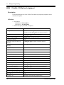
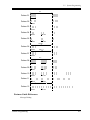
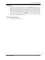
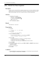
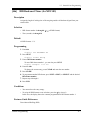
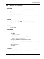
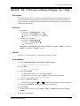
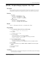
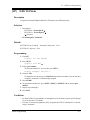
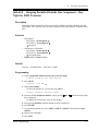
[005] Flexible CO Button Assignment
Description
Used to determine the use of the flexible CO buttons on proprietary telephones from a
centralised telephone.
Selection
• Jack number:
KX-TD816 – 01 through 16
KX-TD1232 – 01 through 64
• Button Code (plus parameter, if required):
Button Code
Parameter
0 (Single-CO)
KX-TD816: 01 through 08 (Outside line number)
KX-TD1232: 01 through 54 (Outside line number)
1 (DSS)
2 through 4 digits (Extension number)
2 (One-Touch Dialling)
16 digits max. (Telephone number)
3 (Message Waiting)
None
3 (Another Extension Message
Waiting)
2 through 4 digits (Another extension number)
3 (Phantom Extension Message
Waiting)
2 through 4 digits (Phantom extension number)
4 (FWD/DND)
None
5 (Save)
None
6 (Account)
None
70 (Conference)
None
71 (Log-In/Log-Out)
None
72 (Phantom Extension)
2 through 4 digits (Phantom extension number)
73 (Night)
None
8 (Voice Mail Transfer)
2 through 4 digits (Voice mail extension number)
90 (Two-Way Record)*
2 through 4 digits (Voice mail extension number)
91 (Two-Way Transfer)*
2 through 4 digits (Voice mail extension number)
92 (Live Call Screening)*
None
93 (Live Call Screening Cancel)*
None
(Loop-CO)
# (Group-CO)
38
None
1 through 8 (Outside line group number)
General Programming
2.1
Button Code
CO (Ringer frequency)
Manager Programming
Parameter
1 through 8 (Ring tone type number)
* Available when this system is connected to a Voice Processing System which supports digital
proprietary telephone integration (e.g. KX-TVP100).
Default
KX-TD816:
All jacks – CO buttons 1 through 8 = Single-CO 01 through 08; Ring tone type 2
Other CO buttons = Not stored
KX-TD1232:
All jacks – CO buttons 1 through 24 = Single-CO 01 through 24; Ring tone type 2
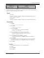
Programming
1. Enter 005.
Display: 005 FLEXIBLE CO
2. Press NEXT.
Display: Jack NO?
3. Enter a jack number.
To enter jack number 01, you can also press NEXT.
Display: PT—PGM Mode
4. Press the CO button which is changed to another button.
The display shows the contents pre-assigned to the button.
Display example: CO-01
5. Enter a button code (plus parameter, if required).
To change the parameter, press CLEAR and enter the new parameter.
6. Press STORE.
7. To programme another CO button of the same jack, repeat steps 4 through 6.
To programme another jack, press SELECT and repeat steps 3 through 6.
8. Press END.
Cancelling
1. Perform the same procedures as steps 1 through 4 above.
2. Enter 2.
3. Press STORE.
4. Press END.
General Programming
39
2.1
Manager Programming
Conditions
• A centralised telephone is a telephone connected to jack 01 or a jack programmed as a
manager extension in programme [006] Operator / Manager Extension Assignment.
• For the KX-TD1232, jack numbers 01 through 32 are for the Master System and 33 through
64 are for the Slave, if available. Jack numbers in the out-of-service system are
unacceptable.
• The number of the CO buttons available depends on the telephone type. (Refer to Buttons
on Proprietary Telephones and Consoles in the Features Guide.)
• If you press the same CO button again in step 5, you can select a desired ringer frequency
for the CO button from eight types of ring tones. When you enter the tone type number (1
through 8), you will hear the selected tone type until STORE is pressed. This selection is
possible only for the CO buttons that have been assigned to Single-CO, Group-CO, or
Loop-CO.
Features Guide References
Button, Flexible
Buttons on Proprietary Telephones and Consoles
40
General Programming
2.1
[006]
Manager Programming
Operator / Manager Extension Assignment
Description
Assigns the jack number for a manager and/or operators. The manager extension can perform
System Programming and manager services. The operators have the ability to perform operator
services.
Selection
• OPE-1 (operator 1) / OPE-2 (operator 2) / MNGER (manager)
• Jack number:
KX-TD816 – 01 through 16
KX-TD1232 – 01 through 64
Default
Operator 1 – Jack 01;
Operator 2 and Manager – Not stored
Programming
1. Enter 006.
Display: 006 OP-1, 2, MGR
2. Press NEXT to programme operator 1.
Display: OPE-1:Jack01
To programme another item, you can also keep pressing NEXT or PREV until the
desired one is displayed.
3. Enter a jack number.
To assign no operator or manager, press CLEAR.
To change the current entry, press CLEAR and enter the new jack number.
4.
5.
6.
7.
Press STORE.
To programme another item, press NEXT or PREV.
Repeat steps 3 through 5.
Press END.
Conditions
• Up to two operators and a manager can be programmed.
• For the KX-TD1232, jack numbers 01 through 32 are for the Master System and 33 through
64 are for the Slave, if available.
• The manager cannot be assigned the jack number of the Console Port set in programme
[007] Console Port and Paired Telephone Assignment.
General Programming
41
2.1
Manager Programming
• If the assigned jack is in eXtra Device Port (XDP) mode, the proprietary telephone jack is
treated as the manager / operator extension.
Features Guide References
Manager Extension
Operator
42
General Programming
2.1
[007]
Manager Programming
Console Port and Paired Telephone Assignment
Description
Assigns the jack numbers for the console and the paired extension.
Selection
• Console number:
KX-TD816 – 1 through 4
KX-TD1232 – 1 through 4 (for Master), 5 through 8 (for Slave)
• Jack number for Console:
KX-TD816 – 02 through 16
KX-TD1232 – 02 through 32 (for Master), 33 through 64 (for Slave)
• Jack number for paired extension:
KX-TD816 – 01 through 16
KX-TD1232 – 01 through 32 (for Master), 33 through 64 (for Slave)
Default
All consoles – Not stored
Programming
1. Enter 007.
Display: 007 DSS CONSOLE
2. Press NEXT.
Display: DSS NO?
3. Enter a console number.
To enter console number 1, you can also press NEXT.
Display example: DSS—1:# P:#
4. Enter a jack number for the console.
To delete the current entry, press CLEAR.
To change the current entry, press CLEAR and enter the new jack number.
.
5. Press
6. Enter a jack number for the paired extension.
To change the current entry, press CLEAR and enter the new jack number.
Display example: DSS—1:#02 P:#03
7. Press STORE.
8. To programme another console, press NEXT or PREV, or SELECT and the desired
console number.
9. Repeat steps 4 through 8.
10.Press END.
General Programming
43
2.1
Manager Programming
Conditions
•
•
•
•
The jack number for the console and that for the paired extension must be entered together.
Multiple consoles cannot be assigned to the same console jack.
Multiple consoles can be paired with the same proprietary telephone jack.
A console jack cannot be assigned the jack 01 and the jack number of manager set in
programme [006] Operator / Manager Extension Assignment.
• If all incoming outside calls are set to ring at the operator extension telephone in programme
[407-408] DIL 1:1 Extension – Day / Night, assigning a console to the operator extension
makes the operator's job much easier.
• If a single line telephone is assigned as the pair extension, the paired console will not
function.
• If a console - assigned jack is programmed for eXtra Device Port (XDP), a single line
telephone can be connected to the jack in parallel with the console.
Features Guide References
Console
44
General Programming
2.1
[008]
Manager Programming
Absent Messages
Description
Used to programme the absent messages. An absent message, if set by the extension user, is
displayed on the calling extension's telephone to show the reason for the user's absence.
Selection
• Message number: 1 through 9
• Message: 16 characters (max.)
Default
1: Will Return Soon
2: Gone Home
3: At Ext %%%
4: Back at %%:%%
5: Out Until %%/%%
6: In a Meeting
7 through 9: Blank (not stored)
Programming
1. Enter 008.
Display: 008 ABSENT MSG.
2. Press NEXT.
Display: MSG NO?
3. Enter a message number.
To enter message number 1, you can also press NEXT.
Display example: MSG1:Will Return
4. Enter the message.
For entering characters, see Section 1.4 Entering Characters.
To delete the current entry, press CLEAR.
To change the current entry, press CLEAR and enter the new message.
5. Press STORE.
6. To programme another message, press NEXT or PREV, or SELECT and the desired
message number.
7. Repeat steps 4 through 6.
8. Press END.
General Programming
45
2.1
Manager Programming
Conditions
• Messages 1 through 6 are programmed at the factory but can be changed.
• You can enter a maximum of seven "%" characters per message which can be programmed
at each user's extension. The extension user can enter 0 through 9, and # for the %
characters. If the user enters digits less than the number of "%" characters, it is
recommended to fill the remaining "%" characters with "#" or " ".
• If there are 4-digit extension numbers available in your system, add one "%" to Message 3.
• To display parts of the message which have scrolled off the display, press
or
.
Features Guide References
Absent Message Capability
46
General Programming
2.1
[009]
Manager Programming
Quick Dial Number Set
Description
Stores up to eight quick dial numbers.
Selection
• Location number: 1 through 8
• Desired number: 16 digits (max.)
Default
All location numbers – Not stored
Programming
1. Enter 009.
Display: 009 QUICK DIAL
2. Press NEXT.
Display: Location NO?
3. Enter a location number.
To enter location number 1, you can also press NEXT.
Display example: 1:Not Stored
4. Enter a desired number.
To delete the current entry, press CLEAR.
To change the current entry, press CLEAR and enter the new number.
5. Press STORE.
6. To programme another location, press NEXT or PREV, or SELECT and the desired
location number.
7. Repeat steps 4 through 6.
8. Press END.
Conditions
• A maximum of sixteen digits, consisting of 0 through 9, and #, can be assigned to a quick
dial number.
• Before programming, assign a feature number for each location first in programme
[100] Flexible Numbering.
Features Guide References
Quick Dialling
General Programming
47
2.1
Manager Programming
[014] VM Name Set
Description
Assigns a name for each voice mail port.
Selection
• Voice Mail (VM) number:
KX-TD816 – 01 through 12
KX-TD1232 – 01 through 24
• Name: 10 characters (max.)
Default
All Voice Mails – V.Mail xx (xx=01 through 24)
Programming
1. Enter 014.
Display: 014 VM PORT NAME
2. Press NEXT.
Display: VM Port NO?
3. Enter a VM number.
To enter VM number 01, you can also press NEXT.
Display example: VM01:V.Mail 01
4. Enter a name.
For entering characters, see Section 1.4 Entering Characters.
To delete the current entry, press CLEAR.
To change the current entry, press CLEAR and enter the new name.
Display example: VM01:Voice No.1
5. Press STORE.
6. To programme another voice mail port, press NEXT or PREV, or SELECT and the desired
voice mail number.
7. Repeat steps 4 through 6.
8. Press END.
Conditions
None
Features Guide References
Voice Mail Integration for Inband
48
General Programming
2.1
[015]
Manager Programming
Budget Management
Description
Assigns the charge limitation of a call on the extension basis.
Selection
• Jack number:
KX-TD816 – 01 through 16 (-1 / -2),
KX-TD1232 – 01 through 64 (-1 / -2),
( =all jacks, -1=first part, -2=second part)
• Charge limitation (Charge): 0 through 99999999
Default
All jacks – 0
Programming
1. Enter 015.
Display: 015 BUDGET MNG
2. Press NEXT.
Display: Jack NO?
3. Enter a jack number.
To enter jack number 01, you can also press NEXT.
Display example: #01-1:
0 $
4. Enter a charge limitation.
To delete the charge limitation, press CLEAR.
5. Press STORE.
6. To programme another jack, press NEXT or PREV, or SELECT and the desired jack
number.
7. Repeat steps 4 through 6.
8. Press END.
Conditions
• If the charge limitation is set "0", no restriction is applied.
• For the KX-TD1232, jack numbers 01 through 32 are for the Master System and 33 through
64 are for the Slave, if available.
• To assign all jack numbers to one selection, press the
display shows the contents programmed for Jack 01.
• The displayed currency can be programmed by [144]
General Programming
key in step 3. In this case, the
Currency Assignment.
49
2.1
Manager Programming
Features Guide References
Budget Management
Charge Fee Reference
50
General Programming
2.1
[017]
Manager Programming
DISA / TIE User Codes
Description
Assigns the Direct Inward System Access (DISA) and TIE User Codes and a Class of Service
(COS) to each code. The code COS determines the toll restriction level of the DISA and TIE
caller.
Warning
When you enable the Outside-to-Outside Line Call feature of DISA function, if a third party
discovers the password (a DISA User Code) of the system, you have a risk that they will make
illegal phone calls using your telephone line, and the cost may be charged to your account.
In order to avoid this problem, we strongly recommend the following points:
1: Carefully maintain the secrecy of the password.
2: Specify a complicated password as long and random as you can make it.
3: Change the password frequently.
Selection
• DISA / TIE user code number: 01 through 32
• DISA / TIE user code: 4 through 10 digits
• COS number: 1 through 8
Default
All DISA / TIE user code numbers – DISA / TIE user code=Blank; COS number=8
Programming
1. Enter 017.
Display: 017 USER CODES
2. Press NEXT.
Display: User Code NO?
3. Enter a DISA / TIE user code number.
To enter user code number 01, you can also press NEXT.
Display example: 01:
C:8
4. Enter a DISA / TIE user code.
To delete the current entry, press CLEAR.
To change the current entry, enter the new code.
to programme COS.
5. Press
6. Enter a COS number.
To change the current entry, enter the new COS number.
7. Press STORE.
General Programming
51
2.1
Manager Programming
8. To programme another user code, press NEXT or PREV, or SELECT and the desired
DISA / TIE user code number.
9. Repeat steps 4 through 8.
10.Press END.
Conditions
• This setting is required if Trunk (Outside line) Security mode is selected in programmes
[439] TIE Security Type and [809] DISA Security Type.
• Each code should be unique and composed of four through ten numerical digits, 0 through
9.
• You cannot leave an entry empty.
Features Guide References
Direct Inward System Access (DISA)
TIE Line Service
52
General Programming
2.2
2.2
[100]
System Programming
System Programming
Flexible Numbering
Description
Assigns the leading digits of extension numbers and feature numbers for system features.
Feature Number List
Number
Feature
Default
01
1st hundred extension block
1
02
2nd hundred extension block
2
03 - 16
3rd through 16th hundred extension block
None
17
Operator call
0 / 9*1
18
Automatic line access / ARS
9 / 0*2
19
Outside line group line access
8
20
System speed dialling
21
Station speed dialling
3
22
Station speed dialling programming
30
23
Doorphone call
31
24
Paging – external
32
25
Paging – external answer / TAFAS answer
42
26
Paging – group
33
27
Paging – group answer
43
28
Call pickup, outside line
4
29
Call pickup, group
40
30
Call pickup, directed
41
31
Call hold
50
32
Call hold retrieve – intercom
51
33
Call hold retrieve – outside line
53
34
Last number redial
#
35
Call park / call park retrieve
52
36
Account code entry
49
37
Door opener
55
General Programming
53
2.2
System Programming
Feature Number List
Number
Default
38
External feature access
39
Station feature clear
790
40
Message waiting
70
41
Outgoing message
36
42
Call forwarding / do not disturb
710
43
Call pickup deny
720
44
Data line security
730
45
Call waiting / OHCA / whisper OHCA
731
46
Executive busy override deny
733
47
Pickup dialling
74
48
Absent message
750
49
Timed reminder
76
50
Electronic station lockout
77
51
Day / Lunch / Break / Night service mode
78
52
Parallel telephone mode
39
53
Background music – external
35
54
LCS password
799
55
Call log, incoming
56
56
Call log lock, incoming
57
57
Timed reminder, remote
7
58
Log-in / log-out
45
59
Automatic callback busy cancel
46
60
Walking COS
47
61
Reserved
62
System working report
6
794
63 - 70
Quick dial location numbers 1 through 8
None
71 - 72
Reserved
None
TIE Line access number
None
Other PBX Extension 01 through 16
None
73
74 - 89
54
Feature
90
Paging – deny
721
91
Hotel application – room status
736
General Programming
2.2
*1
*2
System Programming
For KX-TD1232X = 9, Others = 0
For KX-TD1232X = 0, Others = 9
Selection
• Selection number:
01 through 91 (See "Feature Number List" for the corresponding features.)
• Feature number:
1 or 2 digits (for selection numbers 01 through 16, 74 through 89);
1 through 3 digits (for selection numbers 17 through 73 and 90 through 91)
Default
See "Feature Number List".
Programming
1. Enter 100.
Display: 100 FLEX. NUMBER
2. Press NEXT.
Display: Select NO?
3. Enter a selection number.
To enter selection number 01, you can also press NEXT.
Display example: 01. 1-EXT BL:1
4. Enter the feature number.
To delete the feature number, press CLEAR.
To change the current entry, press CLEAR and enter the new number.
5. Press STORE.
6. To programme another selection, press NEXT or PREV, or SELECT and the desired
selection number.
7. Repeat steps 4 through 6.
8. Press END.
To remove all the feature numbers except selection numbers (01) through (16) 1st
through 16th extension blocks;
1. Enter 100.
2. Press NEXT.
3. Enter 00.
Display: All Feature CLR?
4. Press STORE.
5. Press END.
General Programming
55
2.2
System Programming
Conditions
• Required digits and valid entries for the feature numbers are as follows.
Feature number type
Required digits
Valid entry
Extension blocks / other
PBX extensions
1 or 2 digits
0 through 9
TIE line access number
1 through 3 digits
0 through 9
Other feature numbers
1 through 3 digits
0 through 9,
,#
• It is possible to assign the leading digits for extension numbers of the respective extension
blocks. Assignment of extension blocks defines the limits for programmes
[003] Extension Number Set, [012] ISDN Extension Number Set, [118] Voice Mail
Extension Number Set, [124] Phantom Extension Number Set and [813] Floating
Number Assignment.
• If or # is included in a feature number, dial pulse telephone users cannot access the
feature.
• Double entry and incompatible combinations are invalid. Valid entry examples: 30 and 31,
210 and 211. Invalid entry examples: 5 and 5, 30 and 301.
• If you delete a feature number, the feature cannot be used by dialling operation.
• You can remove all the feature numbers except selections (01) through (16).
• To clear an extension block (01) through (16), it is required to change the corresponding
numbers assigned in programme [003] Extension Number Set, [012] ISDN Extension
Number Set, [118] Voice Mail Extension Number Set, [124] Phantom Extension
Number Set and [813] Floating Number Assignment.
Features Guide References
Flexible Numbering
56
General Programming
2.2
[101]
System Programming
Day / Night Service Switching Mode
Description
This programme is used to determine if night mode is set automatically or manually.
Selection
Manual / Auto (automatic)
Default
Manual
Programming
1. Enter 101.
Display: 101 DAY/NT AUTO
2. Press NEXT.
Display example: D/N Mode:Manual
3. Keep pressing SELECT until the desired selection is displayed.
4. Press STORE.
5. Press END.
Conditions
• If automatic switching is assigned, day / night mode is switched at the time programmed in
[102] Day / Night Service Starting Time.
• The operator and manager can switch the day / night mode at any time.
Features Guide References
Day / Night Service
General Programming
57
2.2
System Programming
[102] Day / Night Service Starting Time
Description
Sets the starting time on a day of the week basis, when automatic day / night switching is
programmed in programme [101] Day / Night Service Switching Mode.
Selection
• Day of the week selection number:
1 (Sunday) / 2 (Monday) / 3 (Tuesday) / 4 (Wednesday) /
5 (Thursday) / 6 (Friday) / 7 (Saturday) / (every day of the week)
• Hour: 1 through 12 / Disable (no switching)
• Minute: 0 through 59
• AM / PM
Default
Every day of the week – Day – 9:00 AM / Night – 5:00 PM
Programming
1. Enter 102.
Display: 102 DAY/NT CLOCK
2. Press NEXT.
Display: Day of Week?
3. Enter the day of the week selection number.
To select Sunday, you can also press NEXT.
Display example: Sun-Day: 9:00 AM
To select night mode, press NEXT.
Display example: Sun-Nig: 5:00 PM
4. Enter the hour.
To set no switching, keep pressing SELECT until "Disable" is displayed and go to step
9.
If SELECT is pressed, the display shows the previous entry. If the previous setting was
"Disable", press SELECT to enter the starting time.
To change the current entry, press CLEAR and enter the new time.
.
5. Press
6. Enter the minute.
To change the current entry, press CLEAR and enter the new minutes.
.
7. Press
8. Press SELECT for AM or PM.
9. Press STORE.
58
General Programming
2.2
System Programming
10.To programme another day / night mode or day of the week, press NEXT or PREV, or
SELECT and the day of the week selection number.
11.Repeat steps 4 through 10.
12.Press END.
Conditions
• To select the desired day, you may keep pressing NEXT in step 3. To assign every day of
the week to one selection, press the key in step 3. In this case, the display shows the
contents programmed for Sunday.
• If day / night switching is not desired, select "Disable" in step 4.
• You cannot leave the entry empty.
Features Guide References
Day / Night Service
General Programming
59
2.2
System Programming
[103] Automatic Access Outside Line Group Assignment
Description
Assigns the sequence in which outside line groups will be accessed when in Automatic Line
Access mode. When a user dials the feature number for automatic line access (default=9/0) or
presses the Loop-CO button, an idle line is searched for in the programmed outside line group
order.
Selection
Outside line group number: 1 through 8 in desired order
Default
12345678
Programming
1. Enter 103.
Display: 103 AUTO CO GRP
2. Press NEXT.
Display example: Access:12345678
3. Enter the outside line group numbers in priority from top to bottom.
To delete the current entry, press CLEAR.
To change the current entry, press CLEAR and enter the new order.
4. Press STORE.
5. Press END.
Conditions
• The system supports a maximum of eight outside line groups.
• Automatic Line Access feature works only if the Automatic Route Selection mode is turned
off in programme [312] ARS Mode.
Features Guide References
Line Preference – Outgoing (Idle Line / No Line / Prime Line)
Outside Line Access
60
General Programming
2.2
[105]
System Programming
Account Codes
Description
Assigns the account codes for Account Code Entry, Verified – All Calls and Verified – Toll
Restriction Override modes. If Verified – All Calls is assigned in programme [508] "Account
Code Entry Mode", an account code is required to make an outside call. If Verified – Toll
Restriction Override is assigned, an account code is only required for a toll call and overrides
toll restriction.
Selection
• Location number: 001 through 128
• Account code: 10 digits (max.)
Default
All locations – Not stored
Programming
1. Enter 105.
Display: 105 ACCT CODES
2. Press NEXT.
Display: Location NO?
3. Enter a location number.
To enter location number 001, you can also press NEXT.
Display example: 001:Not Stored
4. Enter an account code.
To delete the current entry, press CLEAR.
To change the current entry, press CLEAR and enter the new account code.
5. Press STORE.
6. To programme another location, press NEXT or PREV, or SELECT and the desired
location number.
7. Repeat steps 4 through 6.
8. Press END.
Conditions
• Each code has a maximum of 10 digits, consisting of 0 through 9.
• Programme [508] Account Code Entry Mode is used to select the Account Code Entry
mode.
• Account codes having "99" in any part or ending with "9" are invalid, as "99" is used as a
delimiter when entering an account code.
General Programming
61
2.2
System Programming
Features Guide References
Account Code Entry
Toll Restriction
62
General Programming
2.2
[106]
System Programming
Station Hunting Type
Description
Used to enable or disable hunting and set the Station Hunting type for each extension group.
There are six Station Hunting types available:
Circular: all of the extensions in the group are searched until an idle one is found.
Termination: searching stops at the extension which has the largest jack number in the group.
Voice Mail (VM): all of the VM ports of an extension group are searched until an idle one is
found which allows Voice Mail Service.
Automated Attendant (AA): all of the AA ports of an extension group are searched until an
idle one is found which allows AA Service.
Ring Group: all of the extensions in the ring group ring simultaneously.
Uniform Call Distribution (UCD): group members are hunted in a circular way.
Selection
• Extension group number: 1 through 8, ( = all extension groups)
• Disable (no hunting) / Terminate (termination) / Circular / VM (voice mail) /
AA (automated attendant) / RING / UCD
Default
All extension groups – Disable
Programming
1. Enter 106.
Display: 106 STATION HUNT
2. Press NEXT.
Display: EXT GRP NO?
3. Enter an extension group number.
To enter extension group number 1, you can also press NEXT.
Display example: Group1:Disable
4. Keep pressing SELECT until the desired selection is displayed.
5. Press STORE.
6. To programme another extension group, press NEXT or PREV, or SELECT and the
desired extension group number.
7. Repeat steps 4 through 6.
8. Press END.
General Programming
63
2.2
System Programming
Conditions
• Programme [602] Extension Group Assignment is used to assign the extension group
members.
• The system supports a maximum of eight jacks (16 jacks during System Connection for
KX-TD1232) for connection to a Voice Processing System as VM or AA ports.
• To assign all extension groups to one selection, press the key in step 3. In this case, the
display shows the contents programmed for extension group 1.
Features Guide References
Ring Group
Station Hunting
Uniform Call Distribution (UCD)
Voice Mail Integration for Inband
64
General Programming
2.2
[107]
System Programming
System Password
Description
Assigns the password required for entering System Programming mode and for maintenance
from a personal computer.
Selection
Password: 4 through 7 digits
Default
1234
Programming
1. Enter 107.
Display: 107 SYS PASSWORD
2. Press NEXT.
Display: Password:1234
3. Enter a password.
To change the current entry, press CLEAR and enter the new password.
4. Press STORE.
5. Press END.
Conditions
• The password can be from four to seven digits long, consisting of 0 through 9.
• If less than four digits are entered, they are not stored.
• You cannot leave the entry empty.
Features Guide References
System Programming and Diagnosis with Personal Computer
System Programming with Proprietary Telephone
General Programming
65
2.2
System Programming
[108] Automatic Hold by CO / DSS Button
Description
Enables or disables automatically holding an outside call when a DSS (Direct Station
Selection) button on the console or proprietary telephone, or a CO button on a proprietary
telephone is pressed. Through this assignment, each button acts as follows:
– Pressing the DSS button holds an outside call and quickly transfers it to an extension without
pressing the TRANSFER button.
– Pressing another CO button holds the current outside call.
Selection
• Button: DSS or CO
• Enable / Disable
Default
DSS button – Enable, CO button – Disable
Programming
1. Enter 108.
Display: 108 AUTO HOLD
2. Press NEXT to programme the DSS button.
Display example: DSS XFER:Enable
3. Keep pressing SELECT until the desired selection is displayed.
4. Press NEXT to programme the CO button.
Display example: CO Hold :Disable
5. Keep pressing SELECT until the desired selection is displayed.
6. Press STORE.
7. Press END.
Conditions
This assignment applies to all DSS and CO buttons on all consoles and proprietary telephones
in the system.
Features Guide References
Call Hold
Call Transfer
66
General Programming
2.2
[109]
System Programming
Expansion Unit Type
Description
Assigns the type of expansion units to be used in the system.
This allows the system to identify the unit in each expansion unit location.
Selection
KX-TD816
• Areas 1; 2 = C (4 CO) / S2 (2 S0) / S6 (6 S0) / BD (4 DID-Pulse/DTMF) / MD (4 DIDMFC) / EM (4 E&M) / E (EXT) / A (16 SLT)
KX-TD1232
• Master / Slave
• Areas 1; 2; 3 = C (4 CO) / S2 (2 S0) / S6 (6 S0) / PR (1 PRI) / BD (4 DID-Pulse/DTMF)
/ MD (4 DID-MFC) / EM (4 E&M) / EL (1 E1) / E1 (8 EXT1) / E2 (8 EXT2) / A1
(16 SLT1) / A2 (16 SLT2)
(Master system only: PR, EL)
Default
KX-TD816: C;E
KX-TD1232: Master and Slave – C;E1;E2
Programming
KX-TD816
1. Enter 109.
Display: 109 EXPAND C,E1
2. Press NEXT.
Display example: Master:C ;E
3. Keep pressing SELECT until the desired selection in Area 1 is displayed.
4.
5.
6.
7.
Press
to programme Area 2, if required.
Keep pressing SELECT until the desired selection in the Area 2 is displayed.
Press STORE.
Press END.
KX-TD1232
1. Enter 109.
Display: 109 EXPAND C,E1
2. Press NEXT to programme the Master System.
General Programming
67
2.2
System Programming
To programme "Slave", press NEXT again.
Display example: Master:C ;E1;E2
3. Keep pressing SELECT until the desired selection in Area 1 is displayed.
4.
5.
6.
7.
Press
to programme another Area, if required.
Keep pressing SELECT until the desired selection in the Area is displayed.
Repeat steps 4 and 5 until all the required entries are completed.
Press STORE.
If only one system is in operation, go to step 10.
8. Press NEXT to programme the Slave System.
Display example: Slave :C ;E1;E2
9. Repeat steps 3 through 7, if required.
10.Press END.
Conditions
• The following units can be installed in the slots.
– C (4-CO lines): KX-TD180
– S2 (2-ISDN S0 lines): KX-TD280
– S6 (6-ISDN S0 lines): KX-TD286
– PR (1-PRI ISDN line): KX-TD290
– BD (4-DID lines with Pulse/DTMF): KX-TD185
– MD (4-DID lines with MFC): KX-TD185
– EM (4-E&M lines): KX-TD184
– EL (1-E1 line): KX-TD188
– E, E1, E2 (8-Extension lines): KX-TD170
– A, A1, A2 (16-SLT lines): KX-TD174
• There are two expansion areas in the KX-TD816, areas 1 and 2 from bottom to top. One
extension line unit and one outside line (CO / ISDN S0 / DID / E&M) unit can be installed.
• There are three expansion areas in each system for the KX-TD1232, areas 1, 2 and 3 from
bottom to top. Up to two extension line units and one outside line (CO / ISDN S0 / E1 / DID
/ E&M) unit can be installed.
• The KX-TD188 and KX-TD290 can only be installed to the KX-TD1232 Master system.
In this case, the basic and extended outside line in the Slave system cannot be used.
• If the KX-TD290 is installed to the KX-TD1232 Master system, the KX-TD280 or KXTD286 can be installed to the Slave system only to use the ISDN extension lines.
• An out-of-service system is unassignable. In this case, skip steps 8 and 9 for the KXTD1232.
• For the KX-TD1232, if only the Slave system is in operation, the display shows "Slave" in
step 2.
• After changing the setting, turn the Power Switch off and on once. Otherwise, the previous
setting will remain.
68
General Programming
2.2
System Programming
Features Guide References
None
General Programming
69
2.2
System Programming
[110] Caller ID Code Set
Description
Sets the identification code of the calling party (Caller ID Code) to utilise a Caller ID Service
provided by a specific central office (CO). If an ID Code transmitted from the CO is found in
the Caller ID Code Table, the caller's ID Code or name given to the code in programme
[111] Caller ID Name Set is displayed on the telephone. This allows the called party to
recognise the caller.
Selection
• Location number: 001 through 500
• Caller ID Code: 24 digits (max.)
Default
All locations – Not stored
Programming
1. Enter 110.
Display: 110 CALLER ID #
2. Press NEXT.
Display: Location NO?
3. Enter a location number.
To enter location number 001, you can also press NEXT.
Display example: 001:Not Stored
4. Enter a Caller ID Code.
To delete the current entry, press CLEAR.
To change the current entry, press CLEAR and enter the new code.
5. Press STORE.
6. To programme another location, press NEXT or PREV, or SELECT and the desired
location number.
7. Repeat steps 4 through 6.
8. Press END.
Conditions
• Each Caller ID Code has a maximum of 24 digits, consisting of 0 through 9.
• Programme [111] Caller ID Name Set is used to give names to the Caller ID Codes. If an
ID Code is assigned a name, the called party's telephone will show the name in place of the
ID Code.
70
General Programming
2.2
System Programming
• Programme [406] Caller ID Assignment is used to enable the Caller ID Service on an
outside line basis.
Features Guide References
Caller ID
General Programming
71
2.2
System Programming
[111] Caller ID Name Set
Description
With Caller ID Service, the calling party is displayed either by its ID Code or by its name. If
the name display is required, use this programme to give a name to a caller ID Code stored in
programme [110] Caller ID Code Set.
Selection
• Location number: 001 through 500
• Caller ID Name: 15 characters (max.)
Default
All locations – Not stored
Programming
1. Enter 111.
Display: 111 CALLER NAME
2. Press NEXT.
Display: Location NO?
3. Enter a location number.
To enter location number 001, you can also press NEXT.
Display example: 001:Not Stored
4. Enter a Caller ID Name.
For entering characters, see Section 1.4 Entering Characters.
To delete the current entry, press CLEAR.
To change the current entry, press CLEAR and enter the new name.
5. Press STORE.
6. To programme another location, press NEXT or PREV, or SELECT and the desired
location number.
7. Repeat steps 4 through 6.
8. Press END.
Conditions
• Caller ID Name corresponds to the Caller ID Codes stored in programme [110]
Code Set.
Caller ID
Features Guide References
Caller ID
72
General Programming
2.2
[113]
System Programming
VM Status DTMF Set
Description
Sets the DTMF (Dual Tone Multi-Frequency) signals transmitted to your Voice Processing
System (VPS) to inform the VPS of the VPS ports states quickly:
The following signals are sent to the VPS with the assigned DTMF signals:
RBT (ringback tone):
This signal is sent when calling an extension.
BT (busy tone):
This is sent when the called extension is busy.
ROT (reorder tone):
This is sent when the dialled number is invalid.
DND (DND tone):
This is sent when the other extension has DND assigned.
Answer:
This is sent when the other extension answers the call.
Disconnect:
This is sent when the other extension hangs up.
Confirm (confirmation tone):
This is sent when the feature number for "Message Waiting Lamp" is valid.
FWD VM RBT (FWD to VM ringback tone):
Not available (reserved).
FWD VM BT (FWD to VM busy tone):
This is sent when the called extension has set Call Forwarding to VPS.
FWD EXT RBT (FWD to extension ringback tone):
Not available (reserved).
Selection
• RBT / BT / ROT / DND / Answer / Disconnect / Confirm / FWD VM RBT /
FWD VM BT / FWD EXT RBT
• DTMF signal number: 3 digits (max.)
Default
RBT – 1; BT – 2; ROT – 3; DND – 4; Answer – 5; Disconnect – #9; Confirm – 9;
FWD VM RBT – 6; FWD VM BT – 7; FWD EXT RBT – 8
Programming
1. Enter 113.
Display: 113 VM DTMF CMD
2. Press NEXT to programme ringback tone status.
To programme another status, keep pressing NEXT until the desired status is displayed.
General Programming
73
2.2
System Programming
Display example: RBT :1
3. Enter a DTMF signal number.
To delete the current entry, press CLEAR.
To change the current entry, press CLEAR and enter the new number.
4. Press STORE.
5. To programme another selection, keep pressing NEXT or PREV until the desired selection
is displayed.
6. Repeat steps 3 through 5.
7. Press END.
Conditions
• A DTMF signal number can have a maximum of three digits, consisting of 0 through 9, ,
# and PAUSE.
• The DTMF signals are sent to the extensions in the extension group that is assigned as
"VM" or "AA" in programme [106] Station Hunting Type.
Features Guide References
Voice Mail Integration for Inband
74
General Programming
2.2
[114]
System Programming
VM Command DTMF Set
Description
Sets the DTMF (Dual Tone Multi-Frequency) command signals transmitted to your Voice
Processing System (VPS). There are four commands available: Leave Message; Get Message;
Automated Attendant Service; Voice Mail Service. These commands are used in the following
ways:
(A) If your VPS is used for Voice Mail (VM) Service
(1) Call Forwarding / Intercept Routing to Voice Mail
If a call is forwarded to the VPS, your system will send a mailbox number to the VM port. This
allows the caller to leave a message without knowing the mailbox number.
• Required entries (selections):
LV-MSG (Leave Message): This command is transmitted to a VM port if a call is
forwarded or intercepted and rerouted to the port.
AA-SVC (Automated Attendant Service): If AA Service is effective in programme
[990], Area 05-bits 6 and 7, the "AA-SVC" command is sent to a VM port if an incoming
outside call is answered by the VM port.
• Other programming required (programme addresses): [106]; [602]; [609]; [990], Area
05-bits 6 and 7; [990], Area 02-bit 8
(2) Hearing the message at the extension
If the VPS receives a message and lights the MESSAGE button indicator of the dialled
telephone, the telephone user can hear the message by pressing the MESSAGE button.
• Required entries (selections):
GETMSG (Get Message): This command is transmitted to a VM port when the message
receiver presses the MESSAGE button.
VM-SVC (Voice Mail Service): The "VM-SVC" command is a code transmitted
preceding the "GETMSG" command above.
This is effective to switch to VM port when an AA port lights the MESSAGE indicator.
• Other programming required (programme addresses): [609]; [990], Area 02-bit 8
(B) If your VPS is used for Automated Attendant (AA) Service
An AA port answers an incoming outside call to provide AA services, such as call transfer,
receiving a message.
• Required entries (selections):
VM-SVC (Voice Mail Service): The "VM-SVC" command is a code transmitted before
the "LV-MSG" code if an operator transfers a call to an extension and then it is forwarded
to an AA port so that the AA port can be switched to the VM port temporarily.
• Other programming required (programme addresses): [106], [602]
Selection
• LV-MSG / GETMSG / AA-SVC / VM-SVC
• DTMF signal number: 16 digits (max.)
General Programming
75
2.2
System Programming
Default
LV-MSG – H; GETMSG – *H; AA-SVC – #8; VM-SVC – #6
Programming
1. Enter 114.
Display: 114 VM DTMF CMD
2. Press NEXT to programme the LV-MSG command.
To programme another command, keep pressing NEXT until the desired command is
displayed.
Display example: LV-MSG:H
3. Enter a DTMF signal number.
To delete the current entry, press CLEAR.
To change the current entry, press CLEAR and enter the new number.
4. Press STORE.
5. To programme another selection, keep pressing NEXT or PREV until the desired selection
is displayed.
6. Repeat steps 3 through 5.
7. Press END.
Conditions
• A command signal number can have a maximum of 16 digits, consisting of 0 through 9, ,
#, FLASH and PAUSE.
• The FLASH button is available only for LV-MSG and GETMSG commands to store "H"
which means "Home Position".
• If "H" is stored for "LV-MSG", a mailbox number programmed in programme [609] Voice
Mail Access Codes or an extension number will be sent to the VM port (Follow On ID
function). If certain codes are required before and after the ID code, insert "H" between the
codes, as "aaaHbbb". If nothing is stored, it will operate as "H".
• If " H" is stored for "GETMSG", a mailbox number programmed in programme
[609] Voice Mail Access Codes or an extension number will be sent to the port succeeding
the " ".
Features Guide References
Voice Mail Integration for Inband
76
General Programming
2.2
[115]
System Programming
Adjust Time
Description
Used to adjust the time for checking the normality of system data. Every day at the
programmed time, the data adjustment is performed.
Selection
• Hour: 1 through 12
• Minute: 00 through 59
• AM / PM
Default
1:00 AM
Programming
1. Enter 115.
Display: 115 TIME ADJ M/S
2. Press NEXT to programme hour.
Display example: 1:00 AM
3. Enter the hour.
To change the current entry, press CLEAR and enter the new hour.
to programme minute.
4. Press
5. Enter the Minute.
To change the current entry, enter the new minute.
6.
7.
8.
9.
Press
to programme AM / PM.
Press SELECT for AM or PM.
Press STORE.
Press END.
Conditions
• You cannot leave the entry empty.
• Master and slave systems are synchronised with each other.
Features Guide References
None
General Programming
77
2.2
System Programming
[116] ROM Version Display
Description
Confirms the version of ROM of the system.
Display example:
P011A30101A
Version
Date
Selection
System number:
KX-TD816 – 0
KX-TD1232 – 0 (Master) / 1 (Slave)
Default
Not applicable
Programming
1. Enter 116.
Display: 116 ROM VERSION
2. Press NEXT.
Display: System NO?
3. Enter the system number.
The display shows the ROM version of the specified system.
4. To confirm the other system, press SELECT and enter the system number.
The display shows the ROM version of the specified system.
5. Press END.
Conditions
• The out-of-service system number is unacceptable.
• For KX-TD816, you can enter the system number "0" only. Skip step 4.
Features Guide References
None
78
General Programming
2.2
[117]
System Programming
Voice Mail Number Assignment
Description
Assigns the jack number corresponding to the voice mail port for data transmission to the Voice
Processing System. The voice mail port is expandable to six ports (12 ports during System
Connection for KX-TD1232).
This programme is available when this system is connected to a Panasonic Voice Processing
System which supports digital proprietary telephone integration (e.g. KX-TVP100).
Selection
KX-TD816
• Jack number: 02 through 16
KX-TD1232
• Mast (Master) / Slav (Slave)
• Jack number: 02 through 32 / Master; 33 through 64 / Slave
Default
All jacks – Blank
Programming
KX-TD816
1. Enter 117.
Display: 117 VMS PORT ASN
2. Press NEXT.
Display example: Mast1:# # #
3. Enter a jack number.
To delete the current entry, press CLEAR.
To change the current entry, press CLEAR and enter the new jack number.
4.
5.
6.
7.
Press
to enter another jack number.
Repeat steps 3 through 4 to enter another jack number.
Press STORE.
Press NEXT to programme another jack number.
Display example: Mast2:# # #
8. Repeat steps 3 through 5 to enter another jack number.
9. Press STORE.
General Programming
79
2.2
System Programming
10.Press END.
KX-TD1232
1. Enter 117.
Display: 117 VMS PORT ASN
2. Press NEXT to programme the Master System.
Display example: Mast1:# # #
3. Enter a jack number.
To delete the current entry, press CLEAR.
To change the current entry, press CLEAR and enter the new jack number.
4.
5.
6.
7.
Press
to enter another jack number.
Repeat steps 3 through 4 to enter another jack number.
Press STORE.
Press NEXT to programme another jack number.
Display example: Mast2:# # #
8. Repeat steps 3 through 5 to enter another jack number.
9. Press STORE.
10.Press NEXT to programme the Slave System.
Display example: Slav1:# # #
11.Repeat steps 3 through 5 to enter another jack number.
12.Press STORE.
13.Press NEXT to programme another jack number.
Display example: Slav2:# # #
14.Repeat steps 3 through 5 to enter other jack numbers.
15.Press STORE.
16.Press END.
Conditions
• Neither jack number 01 nor the manager extension can be assigned as a voice mail port jack.
• The jack numbers correspond to the voice mail port in numerical order.
Example: Stored jack numbers: Jacks 02, 03, 05, 08, 11, 13
Jack 02=Voice mail numbers 01, 02; Jack 03=Voice mail numbers 03, 04;
Jack 05=Voice mail numbers 05, 06; Jack 08=Voice mail numbers 07, 08;
Jack 11=Voice mail numbers 09, 10; Jack 13=Voice mail numbers 11, 12
Features Guide References
Voice Mail Integration for Digital Proprietary Telephones
80
General Programming
2.2
[118]
System Programming
Voice Mail Extension Number Set
Description
Assigns the extension number for the voice mail number. These numbers can be used the same
way extension numbers are used for station access.
This programme is available when this system is connected to a Panasonic Voice Processing
System which supports digital proprietary telephone integration (e.g. KX-TVP100).
Selection
• Voice mail number (VM):
KX-TD816 – 01 through 12
KX-TD1232 – 01 through 24
• Extension Number: 2 through 4 digits
Default
KX-TD816:
VM-01=165, VM-02=166, VM-03=167, VM-04=168, VM-05=169, VM-06=170, VM07=177, VM-08=178, VM-09=181, VM-10=182, VM-11=183, VM-12=184
KX-TD1232:
VM-01=165, VM-02=166, VM-03=167, VM-04=168, VM-05=169, VM-06=170, VM07=177, VM-08=178, VM-09=181, VM-10=182, VM-11=183, VM-12=184, VM-13=171,
VM-14=172, VM-15=173, VM-16=174, VM-17=175, VM-18=176, VM-19=179, VM20=180, VM-21=185, VM-22=186, VM-23=187, VM-24=188
Programming
1. Enter 118.
Display: 118 VM EXT #
2. Press NEXT.
Display: VM NO?
3. Enter a voice mail number.
To enter voice mail number 01, you can also press NEXT.
Display: VM-01:#02-1:165
4. Enter an extension number.
To change the current entry, press CLEAR and enter the new number.
5. Press STORE.
6. To programme another voice mail number, press NEXT or PREV, or SELECT and the
desired voice mail number.
7. Repeat steps 4 through 6.
8. Press END.
General Programming
81
2.2
System Programming
Conditions
• For the KX-TD1232, VM-01 through VM-12 are for the Master System and VM-13
through VM-24 are for the Slave System, if available.
• You cannot leave an entry empty.
• The first one or two digits of the voice mail extension numbers are subject to programme
[100] Flexible Numbering (01) through (16) 1st through 16th hundred extension blocks.
• The display shows "VM-XX:#YY-1:ZZZ" in step 3. "XX" means the voice mail number.
"YY" means the jack number of the voice mail port programmed in [117] Voice Mail
Number Assignment.
"-1" of YY-1 means the first part of the jack number in digital line.
YY-2 means the second number of the jack number in digital line.
• Double entry and incompatible entry for these numbers are invalid. Valid entry example: 10
and 11, 10 and 110. Invalid entry example: 10 and 106, 210 and 21.
To avoid making an invalid entry, check the other extension numbers. The default of each
extension number is as follows:
[003] Extension Number Set
KX-TD816 – 101 through 116, 201 through 216
KX-TD1232 – 101 through 164, 201 through 264
[012] ISDN Extension Number Set
Not stored.
[124] Phantom Extension Number Set
Not stored.
[813] Floating Number Assignment
KX-TD816 – 191 through 194, 196, 198, 291 through 294, 298, 299
KX-TD1232 – 191 through 194, 196 through 198, 291 through 294, 296 through 299
Features Guide References
Voice Mail Integration for Digital Proprietary Telephones
82
General Programming
2.2
[119]
System Programming
Voice Mail Extension Group Assignment
Description
Assigns each voice mail number to a voice mail extension group number.
This programme is available when this system is connected to a Panasonic Voice Processing
System which supports digital proprietary telephone integration (e.g. KX-TVP100).
Selection
• Voice mail number (VM):
KX-TD816 – 01 through 12,
KX-TD1232 – 01 through 24,
( =all voice mail numbers)
• Voice mail extension group number (EXG): 1 through 8
Default
All voice mail numbers – EXG 1
Programming
1. Enter 119.
Display: 119 VM EXT GROUP
2. Press NEXT.
Display: VM NO?
3. Enter a voice mail number.
To enter voice mail number 01, you can also press NEXT.
Display example: VM-01:#02-1:EXG1
4. Enter the voice mail extension group number.
To delete the current entry, press CLEAR.
To change the current entry, enter the new number.
5. Press STORE.
6. To programme another voice mail number, press NEXT or PREV, or SELECT and the
desired voice mail number.
7. Repeat steps 4 through 6.
8. Press END.
Conditions
• For the KX-TD1232, VM-01 through VM-12 are for the Master System and VM-13
through VM-24 are for the Slave System, if available.
• The display shows "VM-XX:#YY-1:EXG Z" in step 3.
"XX" means a voice mail number. "YY" means the jack number of the voice mail port
General Programming
83
2.2
System Programming
programmed in [117] Voice Mail Number Assignment.
"-1" of YY-1 means the first part of the jack number in digital line.
"YY-2" means the second part of the jack number in digital line.
• To assign all voice mail numbers to one selection, press the key in step 3. In this case, the
display shows the contents programmed for voice mail number 01.
Features Guide References
Voice Mail Integration for Digital Proprietary Telephones
84
General Programming
2.2
[120]
System Programming
User Password
Description
Assigns the password required for entering the User Programming mode.
In the User Programming mode, any display digital proprietary telephone user in the system
can set the Manager Programmings (Programme address: [0XX]).
Selection
Password: 4 through 7 digits
Default
1234
Programming
1. Enter 120.
Display: 120 USR PASSWORD
2. Press NEXT.
Display example: Password:1234
3. Enter a password.
To change the current entry, press CLEAR and enter the new password.
4. Press STORE.
5. Press END.
Conditions
• The password can be from four to seven digits long, consisting of 0 through 9.
• If less than four digits are entered, they will not be stored.
• You cannot leave the entry empty.
Features Guide References
System Programming with Proprietary Telephone
General Programming
85
2.2
System Programming
[121] Walking COS Password
Description
Assigns the password required for Walking COS.
Selection
Password: 4 through 7 digits
Default
1234
Programming
1. Enter 121.
Display: 121 COS PASSWORD
2. Press NEXT.
Display example: Password:1234
3. Enter a password.
To change the current entry, press CLEAR and enter the new password.
4. Press STORE.
5. Press END.
Conditions
• The password can be from four through seven digits long. Valid numbers are from 0
through 9.
• If less than four digits are entered, they will not be stored.
• You cannot leave the entry empty.
Features Guide References
Class of Service (COS)
86
General Programming
2.2
[122]
System Programming
UCD Overflow
Description
Assigns the destination where the call is transferred to when all extensions in the Uniform Call
Distribution (UCD) group are busy. The Time Table number of the overflow extension must
also be assigned.
Selection
• UCD group number: 1 through 8
• Overflow extension number: 2 through 4 digits
• Time Table number: 1 through 4
Default
All UCD groups – Not stored
Programming
1. Enter 122.
Display: 122 UCD OVERFLOW
2. Press NEXT.
Display: UCD NO?
3. Enter a UCD group number.
To enter UCD group number 1, you can also press NEXT.
Display example: UCD1: ,TT:
4. Enter an overflow extension number.
Display example: UCD1:102,TT:
.
5. Press
6. Enter a Time Table number.
Display example: UCD1:102,TT:1
7. Press STORE.
8. Press END.
Conditions
If the overflow extension or Time Table number is not assigned, the system will not answer the
call and waits for any extension to become idle. In this case, Intercept Routing – No Answer
(IRNA) will be employed.
General Programming
87
2.2
System Programming
Features Guide References
Uniform Call Distribution (UCD)
88
General Programming
2.2
[123]
System Programming
UCD Time Table
Description
Assigns the queuing sequence in the Uniform Call Distribution (UCD) Time Table. The
queuing sequences are as follows:
S1: Sends DISA (Direct Inward System Access) outgoing message 1.
S2: Sends DISA outgoing message 2.
S3: Sends DISA outgoing message 3.
S4: Sends DISA outgoing message 4.
TR: Transfers to the overflow extension.
RT: Returns to the top of the sequence.
Blank: Disconnects.
1T: Timer – 16 seconds
2T: Timer – 32 seconds
3T: Timer – 48 seconds
4T: Timer – 64 seconds
Selection
• Time Table number: 1 through 4
• S1 / S2 / S3 / S4 / TR / RT / 1T / 2T / 3T / 4T / Blank
Default
All time tables – Not stored
Programming
1. Enter 123.
Display: 123 UCD T.TABLE
2. Press NEXT.
Display: Table NO?
3. Enter a Time Table number.
To enter Time Table number 1, you can also press NEXT.
Display example: 1:
4. Keep pressing SELECT until the desired selection is displayed.
Display example: 1:S1
5.
6.
7.
8.
Press
.
Repeat steps 4 and 5.
Press STORE.
Press END.
General Programming
89
2.2
System Programming
Conditions
• "Sx" can be assigned in a space other than in the first only when another "Sx" is assigned
in the first space.
• An assignment after "TR", "RT" or "Blank" is not available.
Features Guide References
Uniform Call Distribution (UCD)
90
General Programming
2.2
[124]
System Programming
Phantom Extension Number Set
Description
Assigns the phantom extension numbers. Each number will be assigned to a flexible CO or
DSS (Direct Station Selection) button and used as a Phantom Extension button.
Selection
• Location number: 001 through 128
• Phantom extension number: 2 through 4 digits
Default
All locations – Not stored
Programming
1. Enter 124.
Display: 124 PHANTOM #
2. Press NEXT.
Display: Location NO?
3. Enter a location number.
To enter location number 001, you can also press NEXT.
Display example: 001:Not Stored
4. Enter a phantom extension number.
To delete the current entry, press CLEAR.
To change the current entry, press CLEAR and enter the new number.
5. Press STORE.
6. To programme another location, press NEXT or PREV, or SELECT and the desired
location number.
7. Repeat steps 4 through 6.
8. Press END.
Conditions
• Each phantom extension number has two through four digits, consisting of numbers 0
through 9.
• The first one or two digits of the phantom extension numbers are subject to programme
[100] Flexible Numbering, (01) through (16) 1st through 16th hundred extension blocks.
• Phantom extension numbers and other extension numbers should be different. Double entry
and incompatible entry for these numbers are invalid. Valid entry example: 10 and 11, 10
and 110. Invalid entry example: 10 and 106, 210 and 21.
General Programming
91
2.2
System Programming
To avoid making an invalid entry, check the other extension numbers. The default of each
extension number is as follows:
[003] Extension Number Set
KX-TD816 – 101 through 116, 201 through 216
KX-TD1232 – 101 through 164, 201 through 264
[012] ISDN Extension Number Set
Not stored.
[118] VM Extension Number Set
KX-TD816 – 165 through 178, 181 through 184
KX-TD1232 – 165 through 188
[813] Floating Number Assignment
KX-TD816 – 191 through 194, 196, 198, 291 through 294, 298, 299
KX-TD1232 – 191 through 194, 196 through 198, 291 through 294, 296 through 299
Features Guide References
Phantom Extension
92
General Programming
2.2
[125]
System Programming
Area Code Assignment
Description
Assigns up to ten area codes which are necessary when using the Caller ID feature. By
assigning your area code, the system records the caller's phone number modified by
programmes [126] Caller ID Modification for Local Call and [127] Caller ID Modification
for Long Distance Call.
Selection
• Location number: 01 through 10
• Area code: 1 through 6 digits
Default
All locations – Blank
Programming
1. Enter 125.
Display: 125 AREA CODE
2. Press NEXT.
Display: Location NO?
3. Enter a location number.
To enter location number 01, you can also press NEXT.
Display example: 01:
4. Enter an area code.
To change the current entry, press CLEAR and enter the new area code.
5. Press STORE.
6. To programme another location number, press NEXT or PREV, or SELECT and the
desired location number.
7. Repeat steps 4 through 6.
8. Press END.
Conditions
• The area code can be six digits long. Valid numbers are from 0 through 9.
• The location numbers used in this programme corresponds to those in programme
[126] Caller ID Modification for Local Call.
Features Guide References
Caller ID
General Programming
93
2.2
System Programming
Call Log, Incoming
94
General Programming
2.2
[126]
System Programming
Caller ID Modification for Local Call
Description
Assigns removed digits from the received caller's number of a local call, and adds number to
make the final number which serves as the Caller ID number. The system records the modified
caller's number to the incoming call log list so that the extension user can call back the caller.
Digits are removed from or added to the beginning of the received digits.
Selection
• Location number: 01 through 10
• Number of digits to be deleted: 0 through 9 (0=no deletion)
• Number to be added: 4 digits (max.)
Default
All locations – Deleted number = 0, Added number = Blank
Programming
1. Enter 126.
Display: 126 CID LOCAL
2. Press NEXT.
Display: Location NO?
3. Enter a location number.
To enter location number 01, you can also press NEXT.
Display example: 01:Del0,Add
4. Enter the number of digits to be deleted.
To change the current entry, press CLEAR and enter the new number.
to programme the number to be added, if required.
5. Press
6. Enter the number to be added.
To change the current entry, press CLEAR and enter the new number.
7. Press STORE.
8. To programme another location number, press NEXT or PREV, or SELECT and the
desired location number.
9. Repeat steps 4 through 8.
10.Press END.
Conditions
• The added number has a maximum of 4 digits, consisting of 0 through 9,
General Programming
and #.
95
2.2
System Programming
• There are ten location numbers for modified numbers, which corresponds to those in
programme [125] Area Code Assignment.
Features Guide References
Caller ID
Call Log, Incoming
96
General Programming
2.2
[127]
System Programming
Caller ID Modification for Long Distance Call
Description
Assigns removed digits from the received caller's number of a long distance call, and adds
number to make the final number which serves as the Caller ID number. The system records
the modified caller's number to the incoming call log list so that the extension user can call back
the caller.
Digits are removed from or added to the beginning of the received digits.
Selection
• Number of digits to be deleted: 0 through 9 (0=no deletion)
• Number to be added: 4 digits (max.)
Default
Deleted digits – 0; Added number – Blank
Programming
1. Enter 127.
Display: 127 CID LD
2. Press NEXT.
Display example: Del,Add:0,
3. Enter the number of digits to be deleted.
To change the current entry, press CLEAR and enter the new number.
to programme the number to be added, if required.
4. Press
5. Enter the number to be added.
To change the current entry, press CLEAR and enter the new number.
6. Press STORE.
7. Press END.
Conditions
The added number has a maximum of 4 digits, consisting of 0 through 9,
and #.
Features Guide References
Caller ID
Call Log, Incoming
General Programming
97
2.2
System Programming
[128] PBX Code
Description
Assigns the PBX Code as your location number if the "PBX Code method" is employed for
TIE Line Network calling.
Selection
PBX Code: 1 through 3 digits
Default
Not stored
Programming
1. Enter 128.
Display: 128 PBX CODE
2. Press NEXT.
Display: Code:
3. Enter a PBX Code.
To change the current entry, press CLEAR and enter the new code.
4. Press STORE.
5. Press END.
Conditions
• Valid numbers for the PBX Code are 0 through 9.
• The PBX Code method is: PBX Code + Extension number.
Features Guide References
TIE Line Service
98
General Programming
2.2
[129]
System Programming
E&M Signal Assignment
Description
Assigns the E&M signal. There are three signals available:
Continuous: Continuous E&M (Wink/Immediate)
Pulsed Ans: Pulsed E&M with Answer Signal (Wink only)
Pulsed No Ans: Pulsed E&M without Answer Signal (Wink only)
Selection
Continuous / Pulsed Ans / Pulsed No Ans
Default
Continuous
Programming
1. Enter 129.
Display: 129 E&M SIGNAL
2. Press NEXT.
Display example:Continuous
3. Keep pressing SELECT until the desired selection is displayed.
4. Press STORE.
5. Press END.
Conditions
If you select "Pulsed Ans" or "Pulsed No Ans", you must select "Wink" as the start type.
Features Guide References
TIE Line Service
General Programming
99
2.2
System Programming
[130] Message Waiting Control
Description
Assigns the data ports which communicate with the Message Waiting Lamp Adaptor Unit
(KX-TD194).
Selection
• Unit (TD194) number:
KX-TD816 – 1
KX-TD1232 – 1 through 6
• Jack number:
KX-TD816 – 02 through 16
KX-TD1232 – 02 through 64
Default
All units – Not stored
Programming
1. Enter 130.
Display: 130 MW CONTROL
2. Press NEXT.
Display: MW UNIT NO?
3. Enter a unit number.
To enter unit number 1, you can also press NEXT.
Display example: Unit:1 Jack
4. Enter a jack number.
Display example: Unit:1 Jack:05
5. Press STORE.
6. To programme another unit, press NEXT or PREV, or SELECT and the desired unit
number.
7. Repeat steps 4 and 6.
8. Press END.
Conditions
• The following jacks are not available for this assignment.
Jack 01
The jack for the manager extension
Jacks assigned to voice mail ports
100
General Programming
2.2
System Programming
Jacks assigned to consoles and paired telephones
Jacks already assigned to the message waiting adaptor unit
If the unit is connected to a port which is not assigned as the data port, a clicking sound
may be heard from the unit.
Please make sure that the unit is connected to the assigned port.
• When the data port is assigned properly and the unit is connected to the assigned port, the
unit power indicator lights red. If the assignment and connection are wrong, the power
indicator will flash.
• For the KX-TD1232, unit numbers 1 through 3 are for the Master System, and 4 through 6
are for the Slave System. Jack numbers 02 through 32 are for the Master System and 33
through 64 are for the Slave System.
• After this assignment, the message waiting ring tone will not be sent to single line telephone
users.
Features Guide References
Message Waiting
General Programming
101
2.2
System Programming
[131] Message Waiting Lamp Assignment
Description
Assigns the message waiting light pattern.
Selection
Message waiting light pattern number: 01 through 12
Default
1
Programming
1. Enter 131.
Display: 131 MW LAMP
2. Press NEXT.
Display: MW LAMP NO:1
3. Enter a message waiting light number.
Display example: MW LAMP NO:12
4. Press STORE.
5. Press END.
Conditions
• The available message waiting light patterns are as follows.
102
General Programming
2.2
System Programming
5s
Pattern 01
1.25s
Pattern 02
500 ms
Pattern 03
250 ms
Pattern 04
250 ms
250 ms
500 ms
500 ms
Pattern 05
10± s
Pattern 06
250 ms
20± s
Pattern 07
250 ms
5s
Pattern 08
1.25 s
1.25 s
500 ms
500 ms
250 ms
250 ms
500 ms
1.25 s
1.25 s
500 ms
1.25 s
1.25 s
250 ms
250 ms
Pattern 09
Pattern 10
Pattern 11
Pattern 12
Features Guide References
Message Waiting
General Programming
103
2.2
System Programming
[132] Message Waiting Port Set
Description
Assigns which single line telephone port is connected to the KX-TD194 port.
Selection
• Unit (TD194) number:
KX-TD816 – 1
KX-TD1232 – 1 through 6
• Message waiting port number: 01 through 16
• Single line telephone jack number:
KX-TD816 – 01 through 16
KX-TD1232 – 01 through 64
• Sub port number: 1 or 2 (1 = main port, 2 =XDP single line telephone port)
Default
All units – All message waiting ports – Not stored
Programming
1. Enter 132.
Display: 132 MW PORT SET
2. Press NEXT.
Display: MW UNIT NO?
3. Enter a unit number.
To enter unit number 1, you can also press NEXT.
Display example: U1 MW: J: -
4. Enter a message waiting port number.
Display example: U1 MW:01J: .
5. Press
6. Enter a single line telephone jack number.
Display example: U1 MW:01J:15.
7. Press
8. Enter a sub port number.
Display example: U1 MW:01J:15-2
9. Press STORE.
10.To programme another message waiting port, press NEXT or PREV, or SELECT and the
desired message waiting port number.
11.Repeat steps 5 through 10.
104
General Programming
2.2
System Programming
12.Press END.
Conditions
• To programme another unit, start from step 1.
• For the KX-TD1232, the unit numbers 1 through 3 are for the Master System and 4 through
6 are for the Slave System, and jack numbers 01 through 32 are for Master System and 33
through 64 are for Slave System.
• For the KX-TD1232, single line telephone jacks connected to the KX-TD194 must belong
to the same system as the data port assigned in programme [130].
For example, if the assigned data port is one of the extension jacks in the master system, the
KX-TD194 must be connected to jacks 01 through 32.
On the other hand, if the assigned data port is one of the extension jacks in the slave system,
the KX-TD194 must be connected to jacks 33 through 64.
Programming example for the KX-TD1232
Unit 1
Data port = jack 02
MW port 1 = single line telephone jack 01-2
MW port 3 = single line telephone jack 05-2
Unit 4
Data port = jack 33
MW port 2 = single line telephone jack 34-2
MW port 6 = single line telephone jack 35-1
• A single line telephone jack cannot be assigned to more than one unit.
Features Guide References
Message Waiting
General Programming
105
2.2
System Programming
[134] Hotel Application
Description
Assigns whether the hotel application is enabled or disabled.
Selection
ON / OFF
Default
OFF
Programming
1. Enter 134.
Display: 134 HOTEL ON/OFF
2. Press NEXT.
Display example: Hotel:OFF
3. Keep pressing SELECT until the desired selection is displayed.
4. Press STORE.
5. Press END.
Conditions
If "ON" is selected, the "Hotel" menu is displayed on the operator extension's KX-T7436 or
KX-T7235, and the "Room Status" feature is available.
Features Guide References
Hotel Application – Room Status
106
General Programming
2.2
[135]
System Programming
DID Number Conversion Selection
Description
Selects whether the Direct Inward Dialling (DID) number is allocated as an extension number
or is converted using the Transfer Table.
Selection
EXT Number / Transfer Table
Default
EXT Number
Programming
1. Enter 135.
Display: 135 DID SELECT
2. Press NEXT.
Display: EXT Number
3. Keep pressing SELECT until the desired selection is displayed.
4. Press STORE.
5. Press END.
Conditions
• The DID number is converted from the DID subscriber number using the programmes
[433] DID / TIE Subscriber Number Removed Digit and [434] DID / TIE Added
Number.
• Programmes [136] through [139] are required to use the Transfer Table.
Features Guide References
Direct Inward Dialling (DID)
General Programming
107
2.2
System Programming
[136] DID / DDI Number Assignment
Description
Assigns the Direct Inward Dialling (DID) number which is converted from the DID subscriber
number using the programmes [433] DID / TIE Subscriber Number Removed Digit and
[434] DID / TIE Added Number. And also assigns the Direct Dialling In (DDI) number. If
the converted number matches the number assigned in this programme, it reaches the
destination assigned in programme [137-138] DID / DDI Extension – Day / Night.
Selection
• Location number: 001 through 200
• DID / DDI number: 16 digits (max.)
Default
All locations – Not stored
Programming
1. Enter 136.
Display: 136 DID NUMBER
2. Press NEXT.
Display: Location NO?
3. Enter a location number.
To enter location number 001, you can also press NEXT.
Display example: #001:Not Stored
4. Enter a DID / DDI number.
To delete the current entry, press CLEAR and enter the new number.
To assign no number, press CLEAR.
5. Press STORE.
6. To programme another location, press NEXT or PREV, or SELECT and the desired
location number.
7. Repeat steps 4 through 6.
8. Press END.
Conditions
• There is a maximum of 200 DID / DDI numbers. Each DID / DDI number can be one
through 16 digits, consisting of 0 through 9 and (wild card).
• If the same DID / DDI number is assigned to different locations, only the number at the
lowest location number becomes available. The others are disregarded.
108
General Programming
2.2
System Programming
• To use this programme for DID numbers, "Transfer Table" must be selected beforehand in
programme [135] DID Number Conversion Selection.
• To use this programme for DDI numbers, "Use" must be selected beforehand in programme
[154] DID Transfer Table for DDI Call.
Features Guide References
Direct Dialling In (DDI)
Direct Inward Dialling (DID)
General Programming
109
2.2
System Programming
[137-138]
DID / DDI Extension – Day / Night
Description
Determines the extension which receive a Direct Inward Dialling (DID) or Direct Dialling In
(DDI) call in both the day and night modes.
Selection
• Location number: 001 through 200
• Extension number: 2 through 4 digits / 0 (operator)
Default
All locations – Not stored
Programming
1. Enter a programme address (137 for day or 138 for night).
Display example: 137 DID NUM DAY
2. Press NEXT.
Display: Location NO?
3. Enter a location number.
To enter location number 001, you can also press NEXT.
Display example: #001:Not Stored
4. Enter an extension number.
To change the current entry, press CLEAR and enter the new number.
To disable the DID, press CLEAR.
5. Press STORE.
6. To programme another location, press NEXT or PREV, or SELECT and the desired
location number.
7. Repeat steps 4 through 6.
8. Press END.
Conditions
• Assignable numbers are programmed in the following programmes.
Extension numbers — [003] Extension Number Set
ISDN extension numbers — [012] ISDN Extension Number Set
Voice Mail numbers — [118] Voice Mail Extension Number Set
Phantom numbers — [124] Phantom Extension Number Set
Floating numbers — [813] Floating Number Assignment (For a DID extension, a DISA
floating number is not assignable.)
110
General Programming
2.2
System Programming
• To use this programme for DID, "Transfer Table" must be selected first in programme
[135] DID Number Conversion Selection, and then the DID number must be assigned in
programme [136] DID / DDI Number Assignment.
• To use this programme for DDI, "Use" must be selected first in programme [154] DID
Transfer Table for DDI Call, and then the DDI number must be assigned in programme
[136] DID / DDI Number Assignment.
Features Guide References
Direct Dialling In (DDI)
Direct Inward Dialling (DID)
Day / Night Service
General Programming
111
2.2
System Programming
[139] DID / DDI Extension Name Set
Description
Assigns names to the Direct Inward Dialling (DID) or Direct Dialling In (DDI) extension
assigned in programme [136] DID / DDI Number Assignment.
Selection
• Location number: 001 through 200
• Extension number: 10 characters (max.)
Default
All locations – Not stored
Programming
1. Enter 139.
Display: 139 DID NAME
2. Press NEXT.
Display: Location NO?
3. Enter a location number.
To enter location number 001, you can also press NEXT.
Display example: 001:Not Stored
4. Enter a name.
For entering characters, see Section 1.4 Entering Characters.
To delete the current entry, press CLEAR.
To change the current entry, press CLEAR and enter the new name.
5. Press STORE.
6. To programme another location, press NEXT or PREV, or SELECT and the desired
location number.
7. Repeat steps 4 through 6.
8. Press END.
Conditions
• A DID / DDI extension name is displayed only when the Transfer Table is used.
• You can programme the initial display as the DID / DDI extension name in Station
Programming.
Features Guide References
Direct Dialling In (DDI)
112
General Programming
2.2
System Programming
Direct Inward Dialling (DID)
General Programming
113
2.2
System Programming
[141] Charge Rate Decimal Point Assignment
Description
Assigns how many decimal places to set for the charge rate.
Selection
Number of decimal places: 0 through 8
Default
2
Programming
1. Enter 141.
Display: 141 DECI. POINT
2. Press NEXT.
Display example: Fraction place 2
3. Enter the desired number.
To delete the current entry, press CLEAR.
4. Press STORE.
5. Press END.
Conditions
• This programme is used when the rate is assigned in programme [142] Charge Rate
Assignment. The change in this programme is reflected automatically to programme [142].
• According to this assignment, the charge is displayed during the conversation and shown on
the SMDR print out.
• This assignment is used for the charge fee reference.
Features Guide References
Charge Fee Reference
114
General Programming
2.2
[142]
System Programming
Charge Rate Assignment
Description
Assigns the rate to each outside line.
Selection
• Outside line number:
KX-TD816 – 01 through 08,
KX-TD1232 – 01 through 24,
( =all outside lines)
• Desired number: 10 digits max. (including the decimal point)
Default
All outside lines – 0.00
Programming
1. Enter 142.
Display: 142 CHARGE RATE
2. Press NEXT.
Display: CO Line NO?
3. Enter an outside line number.
To enter outside line number 01, you can also press NEXT.
Display example: CO01: 0.00
4. Enter a charge rate.
To delete the current entry, press CLEAR.
To change the current entry, press CLEAR and enter the new rate.
To enter a decimal point, press the key.
5. Press STORE.
6. To programme another outside line, press NEXT or PREV, or SELECT and the desired
outside line number.
7. Repeat steps 4 through 6.
8. Press END.
Conditions
• For the KX-TD1232, outside lines 01 through 12 are for the Master System and outside
lines 13 through 24 are for the Slave, if available.
• To assign all outside lines to the same selection, press the key in step 3. In this case, the
display shows the contents programmed for outside line 01.
General Programming
115
2.2
System Programming
• A maximum of ten digits, consisting of 0 through 9 and (decimal point), can be assigned
as the rate. The number of spaces depends on the assignment in programme [141] Charge
Rate Decimal Point Assignment.
<Example> To assign the rate "0.25" when the decimal place is 3 (assigned in [141]), enter
"0.250".
Features Guide References
Charge Fee Reference
116
General Programming
2.2
[143]
System Programming
Charge Display Selection
Description
Assigns the initial display format of charge fee.
Selection
in Meter / in Charge
Default
in Meter
Programming
1. Enter 143.
Display: 143 CHARGE METER
2. Press NEXT.
Display example: in Meter
3. Keep pressing SELECT until the desired selection is displayed.
4. Press STORE.
5. Press END.
Conditions
• This programming is only effective when you select for charge (SMDR Output) by
programme [816] SMDR Output Mode.
• This programming will also determine the print-out format of the charge fee reference.
Features Guide References
Charge Fee Reference
Display Message
Station Message Detail Recording (SMDR)
General Programming
117
2.2
System Programming
[144] Currency Assignment
Description
Assigns the currency required for your country.
Selection
2 characters (Max.)
Default
$
Programming
1. Enter 144.
Display: 144 CURRENCY
2. Press NEXT.
Display example: Currency: $
3. Enter a currency.
To delete the current entry, press CLEAR.
To change the current entry, press CLEAR and enter the new currency.
To enter characters, see Section 1.4 Entering Characters.
4. Press STORE.
5. Press END.
Conditions
If more than two digits are entered, they are ignored.
Features Guide References
Charge Fee Reference
Display Message
118
General Programming
2.2
[148]
System Programming
Off-Hook Monitor
Description
Enables or disables to perform the Off-Hook Monitor.
Selection
Enable / Disable
Default
Enable
Programming
1. Enter 148.
Display: 148 HOOK MONITOR
2. Press NEXT.
Display example: Monitor:Enable
3. Keep pressing SELECT until the desired selection is displayed.
4. Press STORE.
5. Press END.
Conditions
Off-Hook Monitor is only available for the KX-T7433 and KX-T7436 telephone users.
Features Guide References
Off-Hook Monitor
General Programming
119
2.2
System Programming
[150] Lunch Service Starting / Ending Time
Description
Sets the Lunch starting and ending time for each day of the week.
Selection
• Day of the week selection number:
1 (Sunday) / 2 (Monday) / 3 (Tuesday) / 4 (Wednesday) / 5 (Thursday) / 6 (Friday) / 7
(Saturday) / (every day of the week)
• Hour: 1 through 12
• Minute: 0 through 59
• AM / PM
Default
Every day of the week – 12:00 – 12:59 PM
Programming
1. Enter 150.
Display: 150 LUNCH TIME
2. Press NEXT.
Display: Day of Week?
3. Enter the day of the week selection number.
To select Sunday, you can also press NEXT.
Display example: Sun-BGN:12:00PM
4. Enter the hour of starting time.
.
5. Press
6. Enter the minute.
To change the current entry, press CLEAR and enter the new minutes.
.
7. Press
8. Press SELECT for AM or PM.
9. Press STORE.
10.To programme another lunch mode or day of the week, press NEXT or PREV, or SELECT
and the day of the week selection number.
11.Repeat steps 4 through 10.
12.Press END.
120
General Programming
2.2
System Programming
Conditions
• This programming can only be used if "Auto (automatic)" is selected in programme
[101] Day / Night Service Switching Mode.
• Lunch / Break service ends at the assigned time.
For example:
If Lunch is 3:00 – 4:00 PM, Day mode starts at 4:01 PM.
If Lunch is 3:00 – 3:59 PM, Day mode starts at 4:00 PM.
Features Guide References
Day / Night Service
General Programming
121
2.2
System Programming
[151] Break Service Starting / Ending Time
Description
Sets the Break starting and ending time for each day of the week.
Selection
• Day of the week selection number:
1 (Sunday) / 2 (Monday) / 3 (Tuesday) / 4 (Wednesday) / 5 (Thursday) / 6 (Friday) / 7
(Saturday) / (every day of the week)
• Hour: 1 through 12
• Minute: 0 through 59
• AM / PM
Default
Every day of the week – 3:00 – 3:29 PM
Programming
1. Enter 150.
Display: 151 BREAK TIME
2. Press NEXT.
Display: Day of Week?
3. Enter the day of the week selection number.
To select Sunday, you can also press NEXT.
Display example: Sun-BGN: 3:00PM
4. Enter the hour of starting time.
To change the current entry, press CLEAR and enter the new time.
.
5. Press
6. Enter the minute.
To change the current entry, press CLEAR and enter the new minutes.
.
7. Press
8. Press SELECT for AM or PM.
9. Press STORE.
10.To programme another break mode or day of the week, press NEXT or PREV, or SELECT
and the day of the week selection number.
11.Repeat steps 4 through 10.
12.Press END.
122
General Programming
2.2
System Programming
Conditions
• This feature can only be used if "Auto (automatic)" is selected in programme [101]
/ Night Service Switching Mode.
• Lunch / Break service ends at the assigned time.
For example:
If Lunch is 3:00 – 4:00 PM, Day mode starts at 4:01 PM.
If Lunch is 3:00 – 3:59 PM, Day mode starts at 4:00 PM.
Day
Features Guide References
Day / Night Service
General Programming
123
2.2
System Programming
[152] Charge Verification Assignment
Description
Assigns the extension which is allowed to refer or clear for the call information on the
extension, outside line, account code, and the total.
Selection
• Jack number:
KX-TD816 – 01 through 16,
KX-TD1232 – 01 through 64,
( =all jacks)
• Enable / Disable
Default
All jacks – Enable
Programming
1. Enter 152.
Display: 152 CHARGE REF
2. Press NEXT.
Display: Jack NO?
3. Enter a jack number.
To enter jack number 01, you can also press NEXT.
Display example: #01:Enable
4. Keep pressing SELECT until the desired selection is displayed.
5. Press STORE.
6. To programme another jack, press NEXT or PREV, or SELECT and the desired jack
number.
7. Press END.
Conditions
• For the KX-TD1232, jack numbers 01 through 32 are for the Master System and 33 through
64 are for the slave, if available.
• To assign all jack numbers to one selection, press the key in step 3.
In this case, the display shows the contents programmed for Jack 01.
Features Guide References
Charge Fee Reference
124
General Programming
2.2
[153]
System Programming
Charge Verification ID Code Set
Description
Assigns an ID code required to refer the charge information.
Selection
4 digits (0000 through 9999)
Default
1234
Programming
1. Enter 153.
Display: 153 CHARGE ID
2. Press NEXT.
Display example: Code:1234
3. Enter an ID code.
To delete the current entry, press CLEAR.
4. Press STORE.
5. Press END.
Conditions
None
Features Guide References
Charge Fee Reference
General Programming
125
2.3
Timer Programming
2.3
Timer Programming
[200] Hold Recall Time
Description
Assigns the length of the hold recall timer. This timer is used to alert an extension that a call
has been held for an extended period of time.
Selection
Time (seconds): 0 through 240 (0=Hold Recall disabled)
Default
60 s
Programming
1. Enter 200.
Display: 200 HOLD RECALL
2. Press NEXT.
Display example: Time: 60 sec
3. Enter the time.
To change the current entry, press CLEAR and enter the new time.
4. Press STORE.
5. Press END.
Conditions
• Select "0" if Hold Recall is not required.
• You cannot leave the entry empty.
Features Guide References
Call Hold
126
General Programming
2.3
[201]
Timer Programming
Transfer Recall Time
Description
Sets the number of rings before transfer recall occurs. If a transferred call is not answered after
the programmed number of rings, the call returns to the original caller.
Selection
Number of rings: 0 through 48 (0=Transfer Recall disabled)
Default
12 rings
Programming
1. Enter 201.
Display: 201 TRAN RECALL
2. Press NEXT.
Display example: Time:12 rings
3. Enter the number of rings.
To change the current entry, press CLEAR and enter the new number of rings.
4. Press STORE.
5. Press END.
Conditions
• One ring is equivalent to five seconds.
• You cannot leave the entry empty.
• Operator 1 can also be the Transfer Recall destination, which can be assigned in programme
[990] System Additional Information, Area 02-Bit 1.
Features Guide References
Call Transfer
General Programming
127
2.3
Timer Programming
[202] Call Forwarding – No Answer Time
Description
Sets the number of rings for the Call Forwarding – No Answer feature. If a call is not answered
after the programmed number of rings, the call is forwarded to the destination.
Selection
Number of rings: 1 through 12
Default
3 rings
Programming
1. Enter 202.
Display: 202 CALL FWD-NA
2. Press NEXT.
Display example: Time: 3 rings
3. Enter the number of rings.
To change the current entry, press CLEAR and enter the new number of rings.
4. Press STORE.
5. Press END.
Conditions
• One ring is equivalent to five seconds.
• This timer is also used for Intercept Routing. If an incoming DISA (Direct Inward System
Access) call to the Intercept Routing destination is not answered before this timer expires,
the call will be disconnected.
• You cannot leave the entry empty.
Features Guide References
Call Forwarding
128
General Programming
2.3
[203]
Timer Programming
Intercept Time
Description
Sets the number of rings for the Intercept Routing – No Answer (IRNA) feature. If a call is not
answered after the programmed number of rings, the call is redirected to the programmed
extension.
Selection
Number of rings: 3 through 48
Default
12 rings
Programming
1. Enter 203.
Display: 203 INTERCEPT
2. Press NEXT.
Display example: Time:12 rings
3. Enter the number of rings.
To change the current entry, press CLEAR and enter the new number of rings.
4. Press STORE.
5. Press END.
Conditions
• One ring is equivalent to five seconds.
• Programmes [409-410] Intercept Extension – Day / Night are used to programme the
destination of Intercept Routing on an outside line group basis in day and night modes.
• If the original extension has set Call Forwarding – No Answer, Intercept Timer starts after
the Call Forwarding.
• You cannot leave the entry empty.
Features Guide References
Intercept Routing
General Programming
129
2.3
Timer Programming
[204] Pickup Dial Waiting Time
Description
Sets the number of seconds for Pickup Dialling. If the telephone user lifts the handset, the
programmed party is called when the time expires.
Selection
Time (seconds): 1 through 5
Default
1s
Programming
1. Enter 204.
Display: 204 PICKUP DIAL
2. Press NEXT.
Display example: Time:1 sec
3. Enter the time.
To change the current entry, enter the new time.
4. Press STORE.
5. Press END.
Conditions
• This time gives the user an opportunity to dial digits before the automatic dialling process
takes place.
Features Guide References
Pickup Dialling
130
General Programming
2.3
[205]
Timer Programming
Extension-to-Outside Line Call Duration Time
Description
Sets the maximum time allowed for a conversation with an outside party. If an outside call is
originated or answered by a programmed extension user and the timer expires, the call is
disconnected.
Selection
Time (minutes): 1 through 64
Default
10 min
Programming
1. Enter 205.
Display: 205 EXT-CO TIME
2. Press NEXT.
Display example: Time:10 min
3. Enter the time.
To change the current entry, press CLEAR and enter the new time.
4. Press STORE.
5. Press END.
Conditions
• This time-out applies to extensions to which limited call duration is assigned by programme
[502] Extension-to-Outside Line Call Duration Limit.
• This time cannot be set to zero or be left empty.
Features Guide References
None
General Programming
131
2.3
Timer Programming
[206] Outside-to-Outside Line Call Duration Time
Description
Sets the maximum time allowed for a conversation between two outside parties. When the
timer expires, the outside-to-outside line call is disconnected.
Selection
Time (minutes): 1 through 64
Default
10 min
Programming
1. Enter 206.
Display: 206 CO-CO TIME
2. Press NEXT.
Display example: Time:10 min
3. Enter the time.
To change the current entry, press CLEAR and enter the new time.
4. Press STORE.
5. Press END.
Conditions
• You cannot leave the entry empty.
Features Guide References
Call Forwarding
Call Transfer
Conference
Direct Inward System Access (DISA)
132
General Programming
2.3
[207]
Timer Programming
First Digit Time
Description
Sets the maximum time allowed between the start of an outside dial tone and the first digit
dialled on an outgoing outside call. If an extension user fails to dial any digits during this time,
the DTMF (Dual Tone Multi-Frequency) receiver is released.
Selection
Time (seconds): 5 through 120
Default
10 s
Programming
1. Enter 207.
Display: 207 1ST DIGIT T
2. Press NEXT.
Display example: Time: 10 sec
3. Enter the time.
To change the current entry, press CLEAR and enter the new time.
4. Press STORE.
5. Press END.
Conditions
• This timer is used for toll restriction checking.
• You cannot leave the entry empty.
Features Guide References
Toll Restriction
General Programming
133
2.3
Timer Programming
[208] Inter Digit Time
Description
Assigns the maximum time allowed between digits on an outgoing toll call. If an extension user
fails to dial any digits during this time, the DTMF (Dual Tone Multi-Frequency) receiver is
released. This timer applies until the Toll Restriction check is completed.
Selection
Time (seconds): 5 through 30
Default
10 s
Programming
1. Enter 208.
Display: 208 INTER DIGIT
2. Press NEXT.
Display example: Time:10 sec
3. Enter the time.
To change the current entry, press CLEAR and enter the new time.
4. Press STORE.
5. Press END.
Conditions
• This timer is used for toll restriction checking.
• You cannot leave the entry empty.
Features Guide References
Toll Restriction
134
General Programming
2.3
[209]
Timer Programming
Automatic Redial Repeat Times
Description
Sets the number of times Automatic Redial is tried. Automatic redialling of the last dialled or
saved number is done up to the specified number of times.
Selection
Number of times: 1 through 30
Default
KX-TD816BX, KX-TD1232(D)BX/ML, KX-TDN1232 – 10 times
KX-TD816HK, KX-TD1232HK – 3 times
KX-TD1232X – 2 times
Programming
1. Enter 209.
Display: 209 AUTO RD QTY
2. Press NEXT.
Display example: Attempt:10
3. Enter the number of times.
To change the current entry, press CLEAR and enter the new number of times.
4. Press STORE.
5. Press END.
Conditions
• Programme [210] Automatic Redial Interval Time is used to set the interval time between
Automatic Redial attempts.
• You cannot leave the entry empty.
Features Guide References
Redial
General Programming
135
2.3
Timer Programming
[210] Automatic Redial Interval Time
Description
Sets the interval time between Automatic Redial attempts.
Selection
Time (seconds): 3 through 120 (
10 is the actual time)
Default
KX-TD816BX, KX-TD1232(D)BX/ML, KX-TDN1232 – 60 s
KX-TD816HK, KX-TD1232HK – 900 s (15 min)
KX-TD1232X – 30 s
Programming
1. Enter 210.
Display: 210 REDIAL TIME
2. Press NEXT.
Display example: Time: 60 sec
3. Enter the time.
To change the current entry, press CLEAR and enter the new time.
4. Press STORE.
5. Press END.
Conditions
• You enter a number from 3 through 120. The actual time is 10 times your input.
• Programme [209] Automatic Redial Repeat Times is used to set the number of times
Automatic Redial is tried.
• You cannot leave the entry empty.
Features Guide References
Redial
136
General Programming
2.3
[211]
Timer Programming
Dial Start Time
Description
Sets the number of milliseconds the system waits before dialling after an outside line is seized.
Selection
Time (milliseconds): 0 through 40 (
100 is the actual time)
Default
KX-TD816BX, KX-TD1232(D)BX/ML/X, KX-TDN1232 – 500 ms
KX-TD816HK, KX-TD1232HK – 1000 ms
Programming
1. Enter 211.
Display: 211 DIAL START
2. Press NEXT.
Display example: Time: 500 msec
3. Enter the time.
To change the current entry, press CLEAR and enter the new time.
4. Press STORE.
5. Press END.
Conditions
• You enter a number from 0 through 40. The actual time is a 100 times your input.
• You cannot leave the entry empty.
Features Guide References
Outside Line Access
General Programming
137
2.3
Timer Programming
[212] Call Duration Count Start Time
Description
Sets the number of seconds the system waits between the end of dialling and the start of the
Station Message Detail Recording (SMDR) timer for outgoing toll calls. When the system has
sent out all the digits to the central office and this timer expires, the system starts counting the
call. A display telephone shows the elapsed time of the call. The starting time and the duration
of a call are recorded in the SMDR record.
Selection
Time (seconds): 0 through 60
Default
0s
Programming
1. Enter 212.
Display: 212 CALL TIMER
2. Press NEXT.
Display example: Time: 0 sec
3. Enter the time.
To change the current entry, press CLEAR and enter the new time.
4. Press STORE.
5. Press END.
Conditions
• The timer starts counting after all the digits are dialled. This timer does not apply to
incoming calls. The timer for incoming calls starts immediately.
• You cannot leave the entry empty.
Features Guide References
Display Message
Station Message Detail Recording (SMDR)
138
General Programming
2.3
[213]
Timer Programming
DISA Delayed Answer Time
Description
Assigns the number of rings between a call received and the answer by the Direct Inward
System Access (DISA) feature.
Selection
Number of rings: 0 through 6
Default
1 ring
Programming
1. Enter 213.
Display: 213 DISA ANSWER
2. Press NEXT.
Display example: Time:1 rings
3. Enter the number of rings.
To change the current entry, enter the new number of rings.
4. Press STORE.
5. Press END.
Conditions
• One ring is equivalent to five seconds.
• You cannot leave the entry empty.
Features Guide References
Direct Inward System Access (DISA)
General Programming
139
2.3
Timer Programming
[214] DISA Prolong Time
Description
Sets the maximum allowable prolonged time for an outside-to-outside line call via the Direct
Inward System Access (DISA) feature. An outside-to-outside line call is initially limited by the
"Outside-to-Outside Line Call Duration Time" (Programme [206]). However, the DISA caller
can prolong the call after hearing the warning tones by pressing any key (except the key).
The DISA prolong time sets the duration of these extended periods.
Selection
Time (minutes): 0 through 7 (0=no prolonging)
Default
3 min
Programming
1. Enter 214.
Display: 214 DISA PROLONG
2. Press NEXT.
Display example: Time:3 min
3. Enter the time.
To change the current entry, enter the new time.
4. Press STORE.
5. Press END.
Conditions
• Do not confuse this parameter with the "Outside-to-Outside Line Call Duration Time"
(Programme [206]) parameter. Programme [206] is used to set the duration time allowed for
an outside-to-outside line call.
• You cannot leave the entry empty.
Features Guide References
Direct Inward System Access (DISA)
140
General Programming
2.3
[215]
Timer Programming
Outgoing Message Time
Description
Sets the maximum allowable recording time for Outgoing Messages (OGM).
Selection
Time (seconds): 0 / 16 / 32 / 64 (0=no recording)
Default
32, 0, 32, 0 (for OGM 1 through 4 from left to right)
Programming
1. Enter 215.
Display: 215 OGM MSG TIME
2. Press NEXT to programme the time for OGM 1.
Display example: OGM:32, 0,32, 0
3. Keep pressing SELECT until the desired selection is displayed.
4.
5.
6.
7.
8.
Press
to programme the time for OGM 2.
Keep pressing SELECT until the desired selection is displayed.
Repeat steps 4 and 5 to programme the time for OGM's 3 and 4.
Press STORE.
Press END.
Conditions
• There are four messages available:
OGM 1: used for DISA (Direct Inward System Access) message 1 or UCD (Uniform
Call Distribution) message 1
OGM 2: used for DISA message 2 or UCD message 2
OGM 3: used for Timed Reminder or UCD message 3
OGM 4: used for UCD message 4
• Enter the times starting from the left for OGM 1 to OGM 4.
• The total time of the outgoing messages cannot exceed 64 seconds.
Features Guide References
Direct Inward System Access (DISA)
Outgoing Message (OGM)
Timed Reminder
Uniform Call Distribution (UCD)
General Programming
141
2.3
Timer Programming
[216] Message Waiting Ring Interval Time
Description
Sets the Message Waiting ring interval time for a single line telephone.
Selection
Time (minutes): 0 through 64 (0=no ring)
Default
0 min
Programming
1. Enter 216.
Display: 216 MW RING TIME
2. Press NEXT.
Display example: Interval: 0 min
3. Enter the time.
To change the current entry, press CLEAR and enter the new time.
4. Press STORE.
5. Press END.
Conditions
• When the interval time is set to "0", the telephone does not ring for Message Waiting
notification.
• Selecting the message waiting ring type, 3 quick rings or 2 normal rings, in programme
[990] System Additional Information, Area 5 - Bit 11 is available. If you prefer soft
ringing, select "3 quick rings". In this case, there may be some kinds of telephones which
do not ring.
Features Guide References
Message Waiting
142
General Programming
2.3
[217]
Timer Programming
Timed Reminder Alarm Ring Time
Description
Sets the number of seconds the Timed Reminder alarm rings.
Selection
Time (seconds): 30 through 240
Default
30 s
Programming
1. Enter 217.
Display: 217 TIMED REMIND
2. Press NEXT.
Display example: Reminder: 30sec
3. Enter the time.
To change the current entry, enter the new time.
4. Press STORE.
5. Press END.
Conditions
None
Features Guide References
Timed Reminder
General Programming
143
2.3
Timer Programming
[218] DISA AA Wait Time
Description
Sets the number of seconds the system waits for a second digit entry. If the timer expires, the
system assumes that the first digit is a DISA (Direct Inward System Access) built-in auto
attendant number if assigned in programme [815] DISA Built-in Automated Attendant
Number.
Selection
Time (seconds): 1 through 5
Default
1s
Programming
1. Enter 218.
Display: 218 DISA AA WAIT
2. Press NEXT.
Display example: Time:1 sec
3. Enter the time.
To change the current entry, enter the new time.
4. Press STORE.
5. Press END.
Conditions
None
Features Guide References
Direct Inward System Access (DISA)
144
General Programming
2.3
[219]
Timer Programming
Call Park Recall Time
Description
Sets the number of rings before call park recall occurs. Call park recall is used to alert an
extension that a call has been parked for an extended period of time.
Selection
Number of rings: 0 through 48 (0=Call Park Recall disabled)
Default
12 rings
Programming
1. Enter 219.
Display: 219 PARK RECALL
2. Press NEXT.
Display example: Time:12 rings
3. Enter the number of rings.
To change the current entry, press CLEAR and enter the new number of rings.
4. Press STORE.
5. Press END.
Conditions
• One ring is equivalent to five seconds.
• Select "0" if Call Park Recall is not required.
• You cannot leave the entry empty.
Features Guide References
Call Park
General Programming
145
2.3
Timer Programming
[220] TIE First / Inter Digit Time
Description
Assigns the maximum time allowed between the start of the dial tone and the first digit dialled
(First Digit Time), and between digits (Inter Digit Time) on an TIE call. If an extension user
fails to dial any digits during this time, the DTMF receiver is released. This timer applies until
the Toll Restriction check is completed.
Selection
Time (seconds): 3 through 30
Default
5s
Programming
1. Enter 220.
Display: 220 TIE TIMER
2. Press NEXT.
Display example: Time:5 sec
3. Enter the time.
To change the current entry, press CLEAR and enter the new time.
4. Press STORE.
5. Press END.
Conditions
• This timer is used for toll restriction checking.
• You cannot leave the entry empty.
Features Guide References
TIE Line Service
Toll Restriction
146
General Programming
2.4
2.4
[300]
TRS / ARS Programming
TRS / ARS Programming
TRS Override for System Speed Dialling
Description
Allows you to enable toll restriction override for System Speed Dial Numbers. If this is
enabled, all extension users can make System Speed Dialling calls with no restriction.
Selection
Enable / Disable
Default
Disable
Programming
1. Enter 300.
Display: 300 TRS SPEED DL
2. Press NEXT.
Display example: Override:Disable
3. Keep pressing SELECT until the desired selection is displayed.
4. Press STORE.
5. Press END.
Conditions
Select "Enable" for toll restriction override; Select "Disable" for toll restriction.
Features Guide References
Toll Restriction
General Programming
147
2.4
TRS / ARS Programming
[301-305]
TRS Denied Code Entry for Levels 2 through 6
Description
These allow you to specify the numbers which are toll-restricted for each toll restriction level
as follows:
Programme [301]: restricts levels 2 through 6
Programme [302]: restricts levels 3 through 6
Programme [303]: restricts levels 4 through 6
Programme [304]: restricts levels 5 through 6
Programme [305]: restricts level 6
Selection
Location number: 01 through 20
Toll call number: 10 digits (max.)
Default
All locations – Not stored
Programming
1. Enter a programme address (301 through 305).
Display example: 301 TRS DENY L–2
2. Press NEXT.
Display: Location NO?
3. Enter a location number.
To enter location number 01, you can also press NEXT.
Display example: 01:Not Stored
4. Enter a toll call number.
To delete the current entry, press CLEAR.
To change the current entry, press CLEAR and enter the new number.
5. Press STORE.
6. To programme another location, press NEXT or PREV, or SELECT and the desired
location number.
7. Repeat steps 4 through 6.
8. Press END.
148
General Programming
2.4
TRS / ARS Programming
Conditions
• There is a maximum of 20 toll call numbers which can be restricted for each programme.
Each number has a maximum of ten digits, consisting of 0 through 9, and . The character
" " can be used as a wild card character.
• Programmes [306-310] TRS Excepted Code Entry for Levels 2 through 6 are used to
assign exceptions to these numbers. Programmes [500-501] Toll Restriction Level – Day
/ Night are used to set the toll restriction value for each COS.
Features Guide References
Toll Restriction
General Programming
149
2.4
TRS / ARS Programming
[306-310]
TRS Excepted Code Entry for Levels 2 through 6
Description
These allow you to assign numbers which are exceptions to the toll restriction specified in
programmes [301] through [305] as follows:
Programme [306]: applies to level 2
Programme [307]: applies to levels 2 through 3
Programme [308]: applies to levels 2 through 4
Programme [309]: applies to levels 2 through 5
Programme [310]: applies to levels 2 through 6
Selection
• Location number: 1 through 5
• Exceptional number: 10 digits (max.)
Default
All locations – Not stored
Programming
1. Enter a programme address (306 through 310).
Display example: 306 TRS ALLOW 2
2. Press NEXT.
Display: Location NO?
3. Enter a location number.
To enter location number 1, you can also press NEXT.
Display example: 1:Not Stored
4. Enter an exceptional number.
To delete the current entry, press CLEAR.
To change the current entry, press CLEAR and enter the new number.
5. Press STORE.
6. To programme another location, press NEXT or PREV, or SELECT and the desired
location number.
7. Repeat steps 4 through 6.
8. Press END.
150
General Programming
2.4
TRS / ARS Programming
Conditions
There is a maximum of five numbers for each programme. Each number has a maximum of ten
digits, consisting of 0 through 9, and . The character " " can be used as a wild card
character.
Features Guide References
Toll Restriction
General Programming
151
2.4
TRS / ARS Programming
[311] Special Carrier Access Codes
Description
Assigns special carrier numbers. This allows the system to recognise the user-dialled special
carrier number in order to insert the required pause and apply toll restriction.
Selection
• Location number: 01 through 20
• Special carrier number: 7 digits (max.)
Default
All locations – Not stored
Programming
1. Enter 311.
Display: 311 CARRIER #
2. Press NEXT.
Display: Location NO?
3. Enter a location number.
To enter location number 01, you can also press NEXT.
Display example: 01:Not Stored
4. Enter a special carrier number.
To delete the current entry, press CLEAR.
To change the current entry, press CLEAR and enter the new number.
5. Press STORE.
6. To programme another location, press NEXT or PREV, or SELECT and the desired
location number.
7. Repeat steps 4 through 6.
8. Press END.
Conditions
There is a maximum of 20 special carrier numbers. Each carrier number has a maximum of
seven digits, consisting of 0 through 9, , and #. You can also use the PAUSE button to enter
a wild card character. It will be displayed as "X".
Features Guide References
Pause Insertion, Automatic
Toll Restriction
152
General Programming
2.4
[312]
TRS / ARS Programming
ARS Mode
Description
Allows you to turn on or off the Automatic Route Selection (ARS) mode. ARS, if enabled,
selects the least expensive route to be used for an outside call.
Selection
On / Off
Default
Off
Programming
1. Enter 312.
Display: 312 ARS MODE SET
2. Press NEXT.
Display example: ARS:Off
3. Press SELECT until the desired selection is displayed.
4. Press STORE.
5. Press END.
Conditions
• If "Off" is selected, the Automatic Line Access feature functions instead of ARS.
• Programmes [313] through [331] are used to programme ARS.
Features Guide References
Automatic Route Selection (ARS)
Outside Line Access
General Programming
153
2.4
TRS / ARS Programming
[313] ARS Time
Description
Assigns times for the four Automatic Route Selection (ARS) time schedules. It is possible to
split a day into four time zones (maximum) so that the least expensive line is selected for that
time. According to the service hours and charges offered by your carriers, enter the starting
time of each zone.
Selection
• Day of the week:
1 (Mon) / 2 (Tue) / 3 (Wed) / 4 (Thu) / 5 (Fri) / 6 (Sat) / 7 (Sun) /
• Time schedule: A / B / C / D
• Time (hour): 1 through 12 / Disable (no schedule)
• AM / PM
(all days)
Default
All days of the week: A – 8:00 AM; B – 5:00 PM; C – 9:00 PM; D – Disable
Programming
1. Enter 313.
Display: 313 ARS TIME SET
2. Press NEXT.
Display: Day of week?
3. Enter the day of the week.
Display example: Mon-A: 8:00 AM
To programme another time schedule, keep pressing NEXT or PREV until the desired
time schedule is displayed.
4. Enter the hour.
To set no schedule (Disable), press SELECT and go to step 6.
If "Disable" is selected, pressing SELECT shows the previous stored hour.
To change the current entry, press CLEAR and enter the new hour.
5.
6.
7.
8.
Press
to select AM / PM.
Press SELECT for AM or PM.
Press STORE.
To programme another time schedule, keep pressing NEXT or PREV until the desired time
schedule is displayed.
9. Repeat steps 4 through 8.
10.Press END.
154
General Programming
2.4
TRS / ARS Programming
Conditions
• Enter a starting time for each time schedule. Select "Disable" for idle schedules.
• You cannot leave an entry empty.
• To assign all days of the week, press the
contents programmed for Monday.
key in step 3. In this case, the display shows the
Features Guide References
Automatic Route Selection (ARS)
General Programming
155
2.4
TRS / ARS Programming
[314-321]
ARS Leading Digit Entry for Plans 1 through 8
Description
By entering numbers into each leading digit plan (programmes below) you are starting the
process to determine which outside line group will be used to route the call.
Programme
[314]
[315]
[316]
[317]
[318]
[319]
[320]
[321]
1
2
3
4
5
6
7
8
Plan
These eight plans are used to analyse the number which the user dials and decide the route plan
for the call. If the user-dialled number is registered in Plan 1, then Routing Plan 1 is selected
for the call. Automatic Route Selection (ARS) Leading Digit Entry for Plans 1 through 8 match
ARS Routing Plans 1 through 8 (programmes [322] through [329]) respectively.
Selection
• Location number: 001 through 100
• Leading digit number: 10 digits (max.)
Default
All locations – Not stored
Programming
1. Enter a program address (314 through 321).
Display example: 314 ARS LEAD D-1
2. Press NEXT.
Display: Location NO?
3. Enter a location number.
To enter location number 001, you can also press NEXT.
Display example: 001:Not Stored
4. Enter a leading digit number.
To delete the current entry, press CLEAR.
To change the current entry, press CLEAR and enter the new number.
5. Press STORE.
6. To programme another location, press NEXT or PREV, or SELECT and the desired
location number.
7. Repeat steps 4 through 6.
8. Press END.
156
General Programming
2.4
TRS / ARS Programming
Conditions
Each number has a maximum of ten digits, consisting of 0 through 9, and . The character
" " can be used as a wild card character (i.e., "do not care" digit). The system scans all the
ARS Leading Digit Plans simultaneously from left to right. The scan ends as soon as the dialled
number matches a table entry. When using a wild card character, it is important to use one in
each digit position that must be scanned. For example, to differentiate local and long distance
calls with the same leading digits: Plan 1) 1; Plan 2) 1-215. Note that three wild card
digits were used to ensure that the system scanned the first four digits. A shorter string of " "s
would send all the calls to the Plan 1 carrier.
Features Guide References
Automatic Route Selection (ARS)
General Programming
157
2.4
TRS / ARS Programming
[322-329]
ARS Routing Plans 1 through 8
Description
Assigns the outside line group and modification plan to be used for each route plan and time
schedule.
Programme
Plan
[322]
[323]
[324]
[325]
[326]
[327]
[328]
[329]
1
2
3
4
5
6
7
8
Selection
• Time schedule: A / B / C / D
• Outside line group number: 1 through 8
• Modification table number: 1 through 8
Default
All time schedules – Not stored
Programming
1. Enter a programme address (322 through 329).
Display example: 322 ARS ROUTE 1
2. Press NEXT to programme time schedule A.
To programme another time schedule, keep pressing NEXT or PREV until the desired
time schedule is displayed.
Display example: A:G M ,G M ,G M
3. Enter an outside line group number.
To delete the current entry, press CLEAR.
To change the current entry, enter the new number.
to enter the paired modification table number.
4. Press
5. Enter a modification table number.
To delete the current entry, press CLEAR.
To change the current entry, enter the new modification table number.
to enter the next priority outside line group number.
6. Press
7. Repeat steps 3 through 6 to enter other outside line group numbers and modification table
numbers.
8. Press STORE.
9. To programme another time schedule, keep pressing NEXT or PREV until the desired time
schedule is displayed.
10.Repeat steps 3 through 9.
158
General Programming
2.4
TRS / ARS Programming
11.Press END.
Conditions
• Up to three outside line groups and modification plans can be assigned for each time
schedule. The outside line group number and modification table number must be entered
together. The highest priority outside line group number and modification table number is
entered first (left to right).
• Programmes [330] ARS Modify Removed Digit and [331] ARS Modify Added
Number are used to make up the eight Modification Tables.
Features Guide References
Automatic Route Selection (ARS)
General Programming
159
2.4
TRS / ARS Programming
[330] ARS Modify Removed Digit
Description
Determines how the dialled number should be modified before transmitting to the central
office. You can delete the digits from the beginning of the dialled number.
Selection
• Modification table number: 1 through 8
• Number of digits to be deleted: 0 through 9 (0=no deletion)
Default
All modification tables – 0
Programming
1. Enter 330.
Display: 330 ARS REMOVE
2. Press NEXT.
Display: Modify Table?
3. Enter a modification table number.
To enter table number 1, you can also press NEXT.
Display example: 1:0
4. Enter the number of digits to be deleted.
To change the current entry, enter the new number.
5. Press STORE.
6. To programme another modification table, press NEXT or PREV, or SELECT and the
desired modification table number.
7. Repeat steps 4 through 6.
8. Press END.
Conditions
There is a maximum of eight Modification Tables, each of which can be given a number of
digits to be deleted.
Features Guide References
Automatic Route Selection (ARS)
160
General Programming
2.4
[331]
TRS / ARS Programming
ARS Modify Added Number
Description
Determines how the dialled number should be modified before transmitting to the central
office. Assigned numbers are added to the beginning of the dialled number.
Selection
• Modification table number: 1 through 8
• Number to be added: 20 digits (max.)
Default
All modification tables – Not stored
Programming
1. Enter 331.
Display: 331 ARS ADD #'S
2. Press NEXT.
Display: Modify Table?
3. Enter a modification table number.
To enter table number 1, you can also press NEXT.
Display example: 1:
4. Enter the number to be added.
To delete the current entry, press CLEAR.
To change the current entry, press CLEAR and enter the new number.
5. Press STORE.
6. To programme another modification table, press NEXT or PREV, or SELECT and the
desired modification table number.
7. Repeat steps 4 through 6.
8. Press END.
Conditions
• There is a maximum of eight Modification Tables, each of which can be given a number to
be added.
• Each number has a maximum of 20 digits, consisting of 0 through 9,
, #, and PAUSE.
Features Guide References
Automatic Route Selection (ARS)
General Programming
161
2.4
TRS / ARS Programming
[332] Extra Entry Table Selection
Description
Selects the code table which enables an extra 400 entries within Denied or Except Code Table.
Selection
• Deny / Except
• Level number: 2 through 6
Default
Except - 2
Programming
1. Enter 332.
Display: 332 TRS EXTRA +
2. Press NEXT.
Display example: Table:Except-2
3. Keep pressing SELECT until the desired selection is displayed.
to enter a level number.
4. Press
5. Enter a level number.
Display example: Table:Except-3
6. Press STORE.
7. Press END.
Conditions
There is a maximum of either 420 toll call numbers for Denied Code Table or a maximum of
405 toll call numbers for Excepted Code Table.
Features Guide References
Toll Restriction
162
General Programming
2.4
[333]
TRS / ARS Programming
TRS Entry Code Assignment for Extra Table
Description
Used to specify the numbers for extra Denied or Excepted Code Table for expansion.
Selection
• Location number: 001 through 400
• Toll call number: 10 digits (max.)
Default
All locations – Not stored
Programming
1. Enter 333.
Display: 333 TRS EXTRA -
2. Press NEXT.
Display: Location NO?
3. Enter a location number.
To enter location number 001, you can also press NEXT.
Display example: 001:Not Stored
4. Enter a toll call number.
To delete the current entry, press CLEAR.
To change the current entry, press CLEAR and enter the new number.
5. Press STORE.
6. To programme another location number, press NEXT or PREV, or SELECT and the
desired location number.
7. Repeat steps 4 through 6.
8. Press END.
Conditions
There is a maximum of either 420 toll call numbers for Denied Code Table or a maximum of
405 toll call numbers for Excepted Code Table. Each number has a maximum of ten digits,
consisting of 0 through 9, and . The character " " can be used as a wild card character.
Features Guide References
Toll Restriction
General Programming
163
2.4
TRS / ARS Programming
[334] Emergency Dial Number Set
Description
Stores up to ten emergency call numbers.
Emergency numbers are not subject to toll restriction, Account Code – Verified mode and
Electronic Station Lockout.
Selection
• Location number: 01 through 10
• Emergency number: 7 digits (max.)
Default
All locations – Not stored
Programming
1. Enter 334.
Display: 334 EMERGENCY #
2. Press NEXT.
Display: Location NO?
3. Enter a location number.
To enter location number 01, you can also press NEXT.
Display example: 01:Not Stored
4. Enter an emergency number.
To delete the current entry, press CLEAR.
To change the current entry, press CLEAR and enter the new number.
5. Press STORE.
6. To programme another location, press NEXT or PREV, or SELECT and the desired
location number.
7. Repeat steps 4 through 6.
8. Press END.
Conditions
Each emergency number has a maximum of seven digits, consisting of 0 through 9.
Features Guide References
Automatic Route Selection (ARS)
Toll Restriction
164
General Programming
2.4
[340]
TRS / ARS Programming
TIE Line Routing Table
Description
The TIE line routing table can be programmed. This table is referenced by the system to
identify the outside line route, when an extension user makes a TIE call.
A routing pattern appropriate for each call is decided by the first three digits (except the TIE
line access number) of the dialled number. This programme assigns the TIE line access number
and outside line group hunt sequence.
Selection
• Location number: 01 through 32
• TIE line access number: 1 through 3 digits
• Outside line group hunt sequence number: 1 through 8 (5 entries max.)
Default
All locations – Not stored
Programming
1. Enter 340.
Display: 340 TIE ROUTE
2. Press NEXT.
Display: Location NO?
3. Enter a location number.
To enter location number 01, you can also press NEXT.
Display example: 01:
4. Enter a TIE line access number.
To delete the current entry, press CLEAR.
To change the current entry, press CLEAR and enter the new number.
to programme the outside line group hunt sequence number.
5. Press
6. Enter an outside line group hunt sequence number.
To delete the current entry, press CLEAR.
To change the current entry, press CLEAR and enter the new number.
7. Press STORE.
8. To programme another location, press NEXT or PREV, or SELECT and the desired
location number.
9. Repeat steps 4 through 8.
10.Press END.
General Programming
165
2.4
TRS / ARS Programming
Conditions
• Each TIE line access number has a maximum of three digits, consisting of 0 through 9 and
. The character " " can be used as a wild card character.
• Programme [341] TIE Modify Removed Digit / Added Number is used to modify the TIE
line access number.
Features Guide References
TIE Line Service
166
General Programming
2.4
[341]
TRS / ARS Programming
TIE Modify Removed Digit / Added Number
Description
Assigns the removed digits and added numbers of a received TIE call. Digits are removed and
added from the beginning of the dialled digits.
Selection
• Location number: 01 through 32
• Number of digits to be deleted: 0 through 4 (0=no deletion)
• Number to be added: 4 digits (max.)
Default
All locations – Deleted digit=0; Added Number=Blank
Programming
1. Enter 341.
Display: 341 TIE MODIFY
2. Press NEXT.
Display: Location NO?
3. Enter a location number.
To enter location number 01, you can also press NEXT.
Display example: 01:0,
4. Enter the number of digits to be deleted.
To change the current entry, press CLEAR and enter the new number.
to programme the number to be added.
5. Press
6. Enter the number to be added.
To change the current entry, press CLEAR and enter the new number.
7. Press STORE.
8. To programme another location, press NEXT or PREV, or SELECT and the desired
location number.
9. Repeat steps 4 through 8.
10.Press END.
Conditions
Each added number has a maximum of 4 digits, consisting of 0 through 9.
General Programming
167
2.4
TRS / ARS Programming
Features Guide References
TIE Line Service
168
General Programming
2.5
2.5
[400]
Outside Line Programming
Outside Line Programming
Outside Line Connection Assignment
Description
Used to identify the outside lines which are connected to the system(s). This prevents users
from originating a call to a line which is not connected.
Selection
• Outside line (CO) number:
KX-TD816 – 01 through 08,
KX-TD1232 – 01 through 54,
( =all outside lines)
• Connect / No Connect
Default
All outside lines – Connect
(If KX-TD290 or KX-TD188 is connected: All outside lines in the Slave System – No
Connect)
Programming
1. Enter 400.
Display: 400 CO CONNECT
2. Press NEXT.
Display: CO Line NO?
3. Enter an outside line number.
To enter outside line number 01, you can also press NEXT.
Display example: CO01:Connect
4. Keep pressing SELECT until the desired selection is displayed.
5. Press STORE.
6. To programme another outside line, press NEXT or PREV, or SELECT and the desired
outside line number.
7. Repeat steps 4 through 6.
8. Press END.
Conditions
• For the KX-TD1232, outside lines 01 through 12 are for the Master System and outside
lines 13 through 24 are for the Slave, if available.
General Programming
169
2.5
Outside Line Programming
• Outside lines 25 through 54 become available when the KX-TD290 or KX-TD188
expansion unit is installed in the KX-TD1232.
• To assign all outside lines to one selection, press the key in step 3. In this case, the display
shows the contents programmed for outside line 01.
Features Guide References
Outside Line Connection Assignment
170
General Programming
2.5
[401]
Outside Line Programming
Outside Line Group Assignment
Description
Each outside line must be assigned to an outside line group. This programme defines the
outside line group assignment for each outside line. For example, if there are multiple
telephone service companies available, the outside lines can be grouped by company.
Selection
• Outside line (CO) number:
KX-TD816 – 01 through 08,
KX-TD1232 – 01 through 54,
( =all outside lines)
• Outside line group (TRG) number: 1 through 8
Default
CO01 – TRG 1;
CO02 – TRG 2;
CO03 – TRG 3;
CO04 – TRG 4;
CO05 – TRG 5;
CO06 – TRG 6;
CO07 – TRG 7;
CO08 – TRG 8 (for KX-TD816)
CO08 through CO54 – TRG 8 (for KX-TD1232)
Programming
1. Enter 401.
Display: 401 CO GROUP 1-8
2. Press NEXT.
Display: CO Line NO?
3. Enter an outside line number.
To enter outside line number 01, you can also press NEXT.
Display example: CO01:TRG1
4. Enter the outside line group number.
To change the current entry, enter the new outside line group number.
5. Press STORE.
6. To programme another outside line, press NEXT or PREV, or SELECT and the desired
outside line number.
7. Repeat steps 4 through 6.
General Programming
171
2.5
Outside Line Programming
8. Press END.
Conditions
• For the KX-TD1232, outside lines 01 through 12 are for the Master System and outside
lines 13 through 24 are for the Slave, if available.
• Outside lines 25 through 54 become available when the KX-TD290 or KX-TD188
expansion unit is installed in the KX-TD1232.
• To assign all outside lines to one outside line group, press the key in step 3. In this case,
the display shows the contents programmed for outside line 01.
Features Guide References
Outside Line Group
172
General Programming
2.5
[402]
Outside Line Programming
Dial Mode Selection
Description
Each outside line can be programmed for DTMF (Dual Tone Multi-Frequency), pulse (rotary)
or call blocking. This programme assigns your choice to each line.
DTMF:
The dialling signals from an extension, either tone or pulse, are converted to tone signals and
transmitted to the outside line.
Pulse:
The dialling signals from an extension, either tone or pulse, are converted to pulse signals and
transmitted to the outside line.
Call blocking:
If your central office can receive both DTMF and pulse signals but you are contracted for pulse,
select this mode. When dialling on the line with a touch tone telephone, only the pulse signals
are sent to the outside line.
Selection
• Outside line (CO) number:
KX-TD816 – 01 through 08,
KX-TD1232 – 01 through 24,
( =all outside lines)
• DTMF / Pulse / C. Block (call blocking)
Default
KX-TD816BX, KX-TD1232(D)BX/ML, KX-TDN1232: All outside lines – Pulse
KX-TD816HK, KX-TD1232HK/X: All outside lines – DTMF
Programming
1. Enter 402.
Display: 402 DIAL MODE
2. Press NEXT.
Display: CO Line NO?
3. Enter an outside line number.
To enter outside line number 01, you can also press NEXT.
Display example: CO01:Pulse
4. Keep pressing SELECT until the desired selection is displayed.
5. Press STORE.
6. To programme another outside line, press NEXT or PREV, or SELECT and the desired
outside line number.
7. Repeat steps 4 through 6.
General Programming
173
2.5
Outside Line Programming
8. Press END.
Conditions
• For the KX-TD1232, outside lines 01 through 12 are for the Master System and outside
lines 13 through 24 are for the Slave, if available.
• To assign all lines to one selection, press the key in step 3. In this case, the display shows
the contents programmed for outside line 01.
• If DTMF is assigned, set the DTMF time of the line in programme [404] DTMF Time.
• If pulse or call blocking is assigned, set the pulse speed of the line in programme
[403] Pulse Speed Selection, and set the pulse break ratio and inter-digit pause in
programme [990] System Additional Information, Area 02 - bit 7, and bits 12 and 11, if
necessary.
Features Guide References
Dial Type Selection
174
General Programming
2.5
[403]
Outside Line Programming
Pulse Speed Selection
Description
An outside line set for pulse or call blocking mode in programme [402] Dial Mode Selection
can have two pulse rates, 10 pps (low) and 20 pps (high). This programme sets the pulse speed
for each outside line set to pulse or call blocking mode.
Selection
• Outside line (CO) number:
KX-TD816 – 01 through 08,
KX-TD1232 – 01 through 24,
( =all outside lines)
• 10 pps / 20 pps
Default
All outside lines – 10 pps
Programming
1. Enter 403.
Display: 403 PULSE SPEED
2. Press NEXT.
Display: CO Line NO?
3. Enter an outside line number.
To enter outside line number 01, you can also press NEXT.
Display example: CO01:10pps
4. Keep pressing SELECT until the desired selection is displayed.
5. Press STORE.
6. To programme another outside line, press NEXT or PREV, or SELECT and the desired
outside line number.
7. Repeat steps 4 through 6.
8. Press END.
Conditions
• For the KX-TD1232, outside lines 01 through 12 are for the Master System and outside
lines 13 through 24 are for the Slave, if available.
• To assign all outside lines to one selection, press the key in step 3. In this case, the display
shows the contents programmed for outside line 01.
• The pulse speed required is determined by the outside line or PBX line.
General Programming
175
2.5
Outside Line Programming
• Programme [990] System Additional Information, Area 02 - bit 7, and bits 12 and 11 are
used to select a pulse break ratio and inter-digit pause, if needed.
Features Guide References
Dial Type Selection
176
General Programming
2.5
[404]
Outside Line Programming
DTMF Time
Description
An outside line set to DTMF (Dual Tone Multi-Frequency) mode in programme [402] Dial
Mode Selection can have two settings. This programme sets the duration of the DTMF signals
sent to an outside line to DTMF mode.
Selection
• Outside line (CO) number:
KX-TD816 – 01 through 08,
KX-TD1232 – 01 through 24,
( =all outside lines)
• Time (milliseconds): 80 / 160
Default
All outside lines – 80 ms
Programming
1. Enter 404.
Display: 404 DTMF TIME
2. Press NEXT.
Display: CO Line NO?
3. Enter an outside line number.
To enter outside line number 01, you can also press NEXT.
Display example: CO01: 80msec
4. Keep pressing SELECT until the desired selection is displayed.
5. Press STORE.
6. To programme another outside line, press NEXT or PREV, or SELECT and the desired
outside line number.
7. Repeat steps 4 through 6.
8. Press END.
Conditions
• For the KX-TD1232, outside lines 01 through 12 are for the Master System and outside
lines 13 through 24 are for the Slave, if available.
• To assign all outside lines to one selection, press the key in step 3. In this case, the display
shows the contents programmed for outside line 01.
• The DTMF time required is determined by the outside line or PBX line.
General Programming
177
2.5
Outside Line Programming
Features Guide References
Dial Type Selection
178
General Programming
2.5
[405]
Outside Line Programming
CPC Signal Detection Incoming Set
Description
Assigns the expected minimum duration of the Calling Party Control (CPC) Signal on
incoming outside calls. If this is programmed, the system disconnects the line when the CPC
Signal is detected.
Selection
• Outside line (CO) number:
KX-TD816 – 01 through 08,
KX-TD1232 – 01 through 24,
( =all outside lines)
• Time (milliseconds): Disable (no detection) / 100 / 200 / 300 / 400 / 500 / 600
Default
All outside lines – Disable
Programming
1. Enter 405.
Display: 405 CPC INCOMING
2. Press NEXT.
Display: CO Line NO?
3. Enter an outside line number.
To enter outside line number 01, you can also press NEXT.
Display example: CO01:Disable
4. Keep pressing SELECT until the desired selection is displayed.
5. Press STORE.
6. To programme another outside line, press NEXT or PREV, or SELECT and the desired
outside line number.
7. Repeat steps 4 through 6.
8. Press END.
Conditions
• For the KX-TD1232, outside lines 01 through 12 are for the Master System and outside
lines 13 through 24 are for the Slave, if available.
• To assign all outside lines to one selection, press the key in step 3. In this case, the display
shows the contents programmed for outside line 01.
• You may disable CPC Signal Detection for an outside line.
General Programming
179
2.5
Outside Line Programming
• Programme [415] CPC Signal Detection Outgoing Set is used to programme CPC Signal
Detection for outgoing outside calls.
Features Guide References
Calling Party Control (CPC) Signal Detection
Direct Inward System Access (DISA)
180
General Programming
2.5
[406]
Outside Line Programming
Caller ID Assignment
Description
Enables the Caller ID feature for the outside lines to which a Caller ID Service is offered by a
Central Office by contract.
Selection
• Outside line (CO) number:
KX-TD816 – 01 through 08,
KX-TD1232 – 01 through 24,
( =all outside lines)
• Enable / Disable
Default
All outside lines – Disable
Programming
1. Enter 406.
Display: 406 CALLER ID CO
2. Press NEXT.
Display: CO Line NO?
3. Enter an outside line number.
To enter outside line number 01, you can also press NEXT.
Display example: CO01:Disable
4. Keep pressing SELECT until the desired selection is displayed.
5. Press STORE.
6. To programme another outside line, press NEXT or PREV, or SELECT and the desired
outside line number.
7. Repeat steps 4 through 6.
8. Press END.
Conditions
• For the KX-TD1232, outside lines 01 through 12 are for the Master System and outside
lines 13 through 24 are for the Slave, if available.
• To assign all outside lines to one selection, press the key in step 3. In this case, the display
shows the contents programmed for outside line 01.
• The following programmes are used to programme Caller ID feature: [110] Caller ID
Code Set and [111] Caller ID Name Set.
General Programming
181
2.5
Outside Line Programming
Features Guide References
Caller ID
182
General Programming
2.5
[407-408]
Outside Line Programming
DIL 1:1 Extension – Day / Night
Description
The Direct In Lines (DIL) 1:1 feature allows incoming outside calls to be directed to a specific
extension. When an outside line is assigned as DIL 1:1, it is necessary to assign the destination.
These programmes specify the extension number for day or night mode.
Selection
• Outside line (CO) number:
KX-TD816 – 01 through 08,
KX-TD1232 – 01 through 24,
( =all outside lines)
• Extension number: 2 through 4 digits / Disable (no DIL 1:1)
Default
All outside lines – Disable (Day / Night)
Programming
1. Enter a programme address (407 for day or 408 for night).
Display example: 407 DIL 1:1 DAY
2. Press NEXT.
Display: CO Line NO?
3. Enter an outside line number.
To enter outside line number 01, you can also press NEXT.
Display example: CO01:Disable
4. Enter an extension number.
To change the current entry, press CLEAR and enter the new number.
To disable DIL 1:1, press CLEAR.
5. Press STORE.
6. To programme another outside line, press NEXT or PREV, or SELECT and the desired
outside line number.
7. Repeat steps 4 through 6.
8. Press END.
Conditions
• For the KX-TD1232, outside lines 01 through 12 are for the Master System and outside
lines 13 through 24 are for the Slave, if available. Outside line numbers in the out-of-service
system are unacceptable.
General Programming
183
2.5
Outside Line Programming
• To assign all outside lines to one selection, press the key in step 3. In this case, the display
shows the contents programmed for outside line 01.
• If an outside line is also programmed for DIL 1:N in programmes [603-604] DIL 1:N
Extension and Delayed Ringing – Day / Night, it is regarded as a DIL 1:1 line.
• Assignable extension numbers are programmed in the following programmes.
Extension numbers – [003] Extension Number Set
ISDN extension numbers – [012] ISDN Extension Number Set
Voice Mail extension numbers – [118] Voice Mail Extension Number Set
Phantom extension numbers – [124] Phantom Extension Number Set
Floating numbers – [813] Floating Number Assignment
Features Guide References
Direct In Lines (DIL)
Direct Inward System Access (DISA)
Day / Night Service
184
General Programming
2.5
[409-410]
Outside Line Programming
Intercept Extension – Day / Night
Description
Intercept Routing provides an automatic re-direction of calls which cannot or have not been
answered (IRNA: Intercept Routing – No Answer). These programmes set the destination in
both day and night modes for each outside line group.
Selection
• Outside line group (TRG) number: 1 through 8, ( =all outside line groups)
• Extension number: 2 through 4 digits / Disable (no Intercept Routing)
Default
All outside line groups – Disable (Day / Night)
Programming
1. Enter a programme address (409 for day or 410 for night).
Display example: 409 INTERCEP DAY
2. Press NEXT.
Display: TRK GRP NO?
3. Enter the outside line group number.
To enter outside line group number 1, you can also press NEXT.
Display example: TRG1:Disable
4. Enter an extension number.
To change the current entry, press CLEAR and enter the new number.
To disable Intercept Routing, press CLEAR.
5. Press STORE.
6. To programme another outside line group, press NEXT or PREV, or SELECT and the
desired outside line group number.
7. Repeat steps 4 through 6.
8. Press END.
Conditions
• To assign all outside line groups to one selection, press the key in step 3. In this case, the
display shows the contents programmed for outside line group 1.
• Programme [401] Outside Line Group Assignment is used to assign each outside line to
an outside line group.
• Assignable extension numbers are programmed in the following programmes.
Extension numbers – [003] Extension Number Set
ISDN extension numbers – [012] ISDN Extension Number Set
General Programming
185
2.5
Outside Line Programming
Voice Mail extension numbers – [118] Voice Mail Extension Number Set
Phantom extension numbers – [124] Phantom Extension Number Set
Floating numbers – [813] Floating Number Assignment
Features Guide References
Intercept Routing
186
General Programming
2.5
[411]
Outside Line Programming
Host PBX Access Codes
Description
Assigns Host PBX access codes. If the system is installed behind a host PBX, an access code
is required to make an outside call. Up to four codes can be stored for an outside line group
assigned to the line.
Selection
• Outside line group (TRG) number: 1 through 8, ( =all outside line groups)
• Access code: 1 or 2 digits, four different entries (max.)
Default
All outside line groups – Not stored
Programming
1. Enter 411.
Display: 411 HOST PBX #'S
2. Press NEXT.
Display: TRK GRP NO?
3. Enter an outside line group number.
To enter outside line group number 1, you can also press NEXT.
Display example: TRG1: , , ,
4. Enter an access code.
To delete the current entry, press CLEAR.
To change the current entry, press CLEAR and enter the new access code.
Display example: TRG1:01, , ,
5. To enter more access codes for the same outside line group, press
and enter the access
codes until all the required entries are completed.
Display example: TRG1:01,08,10,22
6. Press STORE.
7. To programme another outside line group, press NEXT or PREV, or SELECT and the
desired outside line group number.
8. Repeat steps 4 through 7.
9. Press END.
Conditions
• This programme is only required if a host PBX line is connected to the system. Programme
[401] Outside Line Group Assignment is used to assign the line to an outside line group.
General Programming
187
2.5
Outside Line Programming
• There is a maximum of four access codes per outside line group. Each code has one or two
digits, consisting of 0 through 9, and .
• If conflicting access codes (such as 8 and 81) are stored for the same outside line group, the
1-digit code (8) only will be in effect.
• When the programmed codes are dialled, Automatic Pause Insertion and Toll Restriction
are applied to the calls. The programmed pause time (in programme [412] Pause Time) is
automatically inserted after the access code.
• To assign all outside line groups to one selection, press the key in step 3. In this case, the
display shows the contents programmed for outside line group 1.
Features Guide References
External Feature Access
Host PBX Access
Pause Insertion, Automatic
188
General Programming
2.5
[412]
Outside Line Programming
Pause Time
Description
Assigns the length of the pause time. The programmed pause time is automatically inserted
after a line access number or a host PBX access code programmed in [411] Host PBX Access
Codes or manually inserted if the PAUSE button is pressed by the user.
Selection
• Outside line group (TRG) number:1 through 8,
• Time (seconds): 1.5 / 2.5 / 3.5 / 4.5
( =all outside line groups)
Default
All outside line groups – 1.5 s
Programming
1. Enter 412.
Display: 412 PAUSE TIME
2. Press NEXT.
Display: TRK GRP NO?
3. Enter an outside line group number.
To enter outside line group number 1, you can also press NEXT.
Display example: TRG1:1.5sec
4. Keep pressing SELECT until the desired time is displayed.
5. Press STORE.
6. To programme another outside line group, press NEXT or PREV, or SELECT and the
desired outside line group number.
7. Repeat steps 4 through 6.
8. Press END.
Conditions
• To assign all outside line groups to one selection, press the key in step 3. In this case, the
display shows the contents programmed for outside line group 1.
• Programme [401] Outside Line Group Assignment is used to assign each outside line to
an outside line group.
Features Guide References
Host PBX Access
Pause Insertion, Automatic
General Programming
189
2.5
Outside Line Programming
[413] Flash Time
Description
Assigns the length of the flash time. If your system is installed behind a host PBX, External
Feature Access (EFA) is necessary to obtain their services. To enable it, select a required
hooking signal sending time for the outside line group.
Selection
• Outside line group (TRG) number: 1 through 8, ( =all outside line groups)
• Time (milliseconds):
Disable (no EFA) / 80 / 96 / 112 / 200 / 300 / 400 / 500 / 600 / 700 / 800 / 900 / 1000 / 1100
/ 1200
Default
All outside line groups – 600 ms
Programming
1. Enter 413.
Display: 413 FLASH TIME
2. Press NEXT.
Display: TRK GRP NO?
3. Enter an outside line group number.
To enter outside line group number 1, you can also press NEXT.
Display example: TRG1: 600 msec
4. Keep pressing SELECT until the desired time is displayed.
5. Press STORE.
6. To programme another outside line group, press NEXT or PREV, or SELECT and the
desired outside line group number.
7. Repeat steps 4 through 6.
8. Press END.
Conditions
• You may disable EFA, if not required. The Flash feature will be in effect in place of EFA.
Programme [414] Disconnect Time is used to select the time required for the Flash
feature.
• The flash time required is determined by the central office or the host PBX lines.
• To assign all outside line groups to one selection, press the key in step 3. In this case, the
display shows the contents programmed for outside line group 1.
190
General Programming
2.5
Outside Line Programming
• Programme [401] Outside Line Group Assignment is used to assign each outside line to
an outside line group.
Features Guide References
External Feature Access
Flash
General Programming
191
2.5
Outside Line Programming
[414] Disconnect Time
Description
Determines the amount of time between successive accesses to the same outside line.
Selection
• Outside line group (TRG) number: 1 through 8,
• Time (seconds): 1.5 / 4.0
( =all outside line groups)
Default
All outside line groups – 1.5 s
Programming
1. Enter 414.
Display: 414 DISCONNECT
2. Press NEXT.
Display: TRK GRP NO?
3. Enter an outside line group number.
To programme outside line group number 1, you can also press NEXT.
Display example: TRG1:1.5sec
4. Keep pressing SELECT until the desired time is displayed.
5. Press STORE.
6. To programme another outside line group, press NEXT or PREV, or SELECT and the
desired outside line group number.
7. Repeat steps 4 through 6.
8. Press END.
Conditions
• The disconnect time must be longer than the requirements of the central office or the host
PBX.
• To assign all outside line groups to one selection, press the key in step 3. In this case, the
display shows the contents programmed for outside line group 1.
• Programme [401] Outside Line Group Assignment is used to assign each outside line to
an outside line group.
Features Guide References
Flash
192
General Programming
2.5
[415]
Outside Line Programming
CPC Signal Detection Outgoing Set
Description
Enables or disables Calling Party Control (CPC) Signal Detection during the time between the
originated outside call and the established outside call. If this is enabled, the system
disconnects the line with the time set in programme [405] CPC Signal Detection Incoming Set
when the CPC Signal is detected.
Selection
• Outside line (CO) number:
KX-TD816 – 01 through 08,
KX-TD1232 – 01 through 24,
( =all outside lines)
• Enable (detection) / Disable (no detection)
Default
Disable
Programming
1. Enter 415.
Display: 415 CPC OUTGOING
2. Press NEXT.
Display: CO Line NO?
3. Enter an outside line number.
To enter outside line number 01, you can also press NEXT.
Display example: CO01:Disable
4. Keep pressing SELECT until the desired selection is displayed.
5. Press STORE.
6. To programme another outside line, press NEXT or PREV, or SELECT and the desired
outside line number.
7. Repeat steps 4 through 6.
8. Press END.
Conditions
• Some central offices (CO) may send CPC-like signals during the dialling sequence and an
attempt to make a call may be terminated. If your CO is such a type, select "Disable".
• Programme [405] CPC Signal Detection Incoming Set is used to set CPC Signal Detection
Time.
General Programming
193
2.5
Outside Line Programming
• For the KX-TD1232, outside lines 01 through 12 are for the Master System and outside
lines 13 through 24 are for the Slave, if available.
• To assign all outside lines to one selection, press the key in step 3. In this case, the display
shows the contents programmed for outside line 01.
Features Guide References
Calling Party Control (CPC) Signal Detection
Direct Inward System Access (DISA)
194
General Programming
2.5
[416]
Outside Line Programming
Reverse Circuit Assignment
Description
Enables or disables Reverse Circuit detection.
This programme is only available for the following models: KX-TD816BX/HK, KXTD1232DBX/ML, TDN1232.
Selection
• Outside line (CO) number:
KX-TD816 – 01 through 08,
KX-TD1232 – 01 through 24,
( =all outside lines)
• Regular (no detection) / Reverse (detection)
Default
Regular
Programming
1. Enter 416.
Display: 416 REV. CURRENT
2. Press NEXT.
Display: CO Line NO?
3. Enter an outside line number.
To enter outside line number 01, you can also press NEXT.
Display example: CO01:Regular
4. Keep pressing SELECT until the desired selection is displayed.
5. Press STORE.
6. To program another outside line, press NEXT or PREV, or SELECT and the desired
outside line number.
7. Repeat steps 4 through 6.
8. Press END.
Conditions
To assign all outside lines to one selection, press the
shows the contents programmed for outside line 01.
key in step 3. In this case, the display
Features Guide References
Reverse Circuit
General Programming
195
2.5
Outside Line Programming
[417] Outside Line Name Assignment
Description
Assigns a name to each outside line so that the extension user can view the outside line number
and name when receiving an outside call. If Caller ID is assigned, each extension can select
either the initial display, Caller ID or outside line name, by Station Programming.
Selection
• Outside line (CO) number:
KX-TD816 – 01 through 08,
KX-TD1232 – 01 through 54,
( =all outside lines)
• Name: 10 characters (max.)
Default
All outside lines – Not stored
Programming
1. Enter 417.
Display: 417 CO LINE NAME
2. Press NEXT.
Display: CO Line NO?
3. Enter an outside line number.
To enter outside line number 01, you can also press NEXT.
Display example: CO01:Not Stored
4. Enter a name.
For entering characters, see Section 1.4 Entering Characters.
To delete the current entry, press CLEAR.
To change the current entry, press CLEAR and enter the new name.
5. Press STORE.
6. To programme another outside line, press NEXT or PREV, or SELECT and the desired
outside line number.
7. Repeat steps 4 through 6.
8. Press END.
Conditions
• For the KX-TD1232, outside lines 01 through 12 are for the Master System and outside
lines 13 through 24 are for the Slave, if available.
196
General Programming
2.5
Outside Line Programming
• Outside lines 25 through 54 become available when the KX-TD290 or KX-TD188
expansion unit is installed in the KX-TD1232.
• To assign all outside lines to one selection, press the key in step 3. In this case, the display
shows the contents programmed for outside line 01.
Features Guide References
Display Message
Incoming Outside Call Information Display
General Programming
197
2.5
Outside Line Programming
[430] DID / TIE Format Number Assignment
Description
Assigns a Direct Inward Dialling (DID) and TIE format number to each outside line group.
Selection
• Outside line group (TRG) number: 1 through 8,
• DID / TIE format number: 1 through 8
( =all outside line groups)
Default
All outside line groups – Not stored
Programming
1. Enter 430.
Display: 430 MODIFY FORM
2. Press NEXT.
Display: TRK GRP NO?
3. Enter an outside line group number.
To enter outside line group number 1, you can also press NEXT.
Display example: TRG1:Not Stored
4. Enter a DID / TIE format number.
To change the current entry, press CLEAR and enter the new number.
5. Press STORE.
6. To programme another outside line group, press NEXT or PREV, or SELECT and the
desired outside line group number.
7. Repeat steps 4 through 6.
8. Press END.
Conditions
This is the first and basic programming for the DID / TIE feature. If this assignment is changed,
it will affect other programming ([431] through [435]).
Features Guide References
Direct Inward Dialling (DID)
E1 Line Service
TIE Line Service
198
General Programming
2.5
[431]
Outside Line Programming
DID / TIE Incoming Assignment
Description
Assigns a DID / TIE incoming method, immediate or wink, to each DID / TIE format according
to your central office service.
Immediate: Incoming DID and TIE calls can be received right after the receiving signal
arrives.
Wink: Incoming DID and TIE calls can be received after the wink signal is transmitted to the
central office (after the receiving signal arrives).
Selection
• DID / TIE format number: 1 through 8,
• Immediate / Wink
( =all DID / TIE formats)
Default
All DID / TIE formats – Wink
Programming
1. Enter 431.
Display: 431 SIGNAL IN
2. Press NEXT.
Display: Format NO?
3. Enter a DID / TIE format number.
To enter DID / TIE format number 1, you can also press NEXT.
Display example: 1:Wink
4. Keep pressing SELECT until the desired selection is displayed.
5. Press STORE.
6. To programme another DID / TIE format, press NEXT or PREV, or SELECT and the
desired DID / TIE format number.
7. Repeat steps 4 through 6.
8. Press END.
Conditions
To assign all DID / TIE formats to one selection, press the key in step 3. In this case, the
display shows the contents programed for DID / TIE format number 1.
Features Guide References
Direct Inward Dialling (DID)
General Programming
199
2.5
Outside Line Programming
E1 Line Service
TIE Line Service
200
General Programming
2.5
[432]
Outside Line Programming
DID / TIE Outgoing Assignment
Description
Assigns a DID and TIE outgoing method, immediate or wink, to each DID / TIE format
according to your central office service.
Immediate: Outgoing DID and TIE numbers can be transmitted right after seizing the outside
line.
Wink: Outgoing DID and TIE numbers can be transmitted after receiving the wink signal from
the central office after seizing the outside line.
Selection
• DID / TIE format number: 1 through 8,
• Immediate / Wink
( =all DID / TIE formats)
Default
All DID / TIE formats – Wink
Programming
1. Enter 432.
Display: 432 SIGNAL OUT
2. Press NEXT.
Display: Format NO?
3. Enter a DID / TIE format number.
To enter DID / TIE format number 1, you can also press NEXT.
Display example: 1:Wink
4. Keep pressing SELECT until the desired selection is displayed.
5. Press STORE.
6. To programme another DID / TIE format, press NEXT or PREV, or SELECT and the
desired DID / TIE format number.
7. Repeat steps 4 through 6.
8. Press END.
Conditions
• The time the system waits for the confirmation wink signal can be programmed in
programme [435] DID / TIE Wink Time Out Assignment.
The system disconnects the outside line when the time-out time expires.
• To assign all DID / TIE formats to one selection, press the key in step 3.
In this case, the display shows the contents programmed for DID / TIE format number 1.
General Programming
201
2.5
Outside Line Programming
Features Guide References
Direct Inward Dialling (DID)
E1 Line Service
TIE Line Service
202
General Programming
2.5
[433]
Outside Line Programming
DID / TIE Subscriber Number Removed Digit
Description
Assigns the removed digits of received a DID and TIE subscriber number for each DID / TIE
format. In this case, digits are removed from the beginning of the received digits.
Selection
• DID / TIE format number: 1 through 8
• Number of digits to be deleted (RMV): 0 through 6 (0=no deletion)
Default
All DID / TIE formats – RMV:0
Programming
1. Enter 433.
Display: 433 REMOVE DIAL
2. Press NEXT.
Display: Format NO?
3. Enter a DID / TIE format number.
To enter DID / TIE format number 1, you can also press NEXT.
Display example: 1:0
4. Enter the number of digits to be deleted.
To change the current entry, press CLEAR and enter the new number.
5. Press STORE.
6. To programme another DID / TIE format, press NEXT or PREV, or SELECT and the
desired DID / TIE format number.
7. Repeat steps 4 through 6.
8. Press END.
Conditions
• You cannot leave the entry empty.
• You must confirm with your central office regarding the number of digits being sent.
Features Guide References
Direct Inward Dialling (DID)
E1 Line Service
TIE Line Service
General Programming
203
2.5
Outside Line Programming
[434] DID / TIE Added Number
Description
Assigns the added number to the DID and TIE subscriber number which is determined in
programme [433] DID / TIE Subscriber Number Removed Digit. This makes the final
number which serves as the extension number. Note that digits are inserted at the beginning of
the number.
Selection
• DID / TIE format number: 1 through 8
• Number to be added: 4 digits (max.)
Default
All DID / TIE formats – Blank
Programming
1. Enter 434.
Display: 434 ADD DIAL
2. Press NEXT.
Display: DID Format NO?
3. Enter a DID / TIE format number.
To enter DID format number 1, you can also press NEXT.
Display example: 1:
4. Enter the number to be added.
To change the current entry, press CLEAR and enter the new number.
5. Press STORE.
6. To programme another DID / TIE format, press NEXT or PREV, or SELECT and the
desired DID / TIE format number.
7. Repeat steps 4 through 6.
8. Press END.
Conditions
• Each added number has a maximum of 4 digits, consisting of 0 through 9.
Features Guide References
Direct Inward Dialling (DID)
E1 Line Service
TIE Line Service
204
General Programming
2.5
[435]
Outside Line Programming
DID / TIE Wink Time Out Assignment
Description
The DID / TIE outgoing method can be set to the wink mode in programme [432] DID / TIE
Outgoing Assignment. This programme sets the time the system waits for the confirmation
wink signal after an outside line is seized according to your central office service.
Selection
• DID / TIE format number: 1 through 8,
• Time: 1 through 127 (
( =all DID / TIE formats)
64 milliseconds is the actual time)
Default
All DID / TIE formats – 16
Programming
1. Enter 435.
Display: 435 WINK TIMEOUT
2. Press NEXT.
Display: Format NO?
3. Enter a DID / TIE format number.
To enter DID / TIE format number 1, you can also press NEXT.
Display example: 1:16
4. Enter the time.
To change the current entry, press CLEAR and enter the new number.
5. Press STORE.
6. To programme another DID / TIE format, press NEXT or PREV, or SELECT and the
desired DID / TIE format number.
7. Repeat steps 4 through 6.
8. Press END.
Conditions
• You cannot leave the entry empty.
• To assign all DID / TIE formats to one selection, press the key in step 3. In this case, the
display shows the contents programmed for DID / TIE format number 1.
Features Guide References
Direct Inward Dialling (DID)
General Programming
205
2.5
Outside Line Programming
E1 Line Service
TIE Line Service
206
General Programming
2.5
[436]
Outside Line Programming
Outside-to-TIE Transfer
Description
Enables or disables transferring an incoming outside call to the TIE line on an outside line
group basis. This restriction applies to the following: 1) A TIE call using DISA 2) Call
Forwarding to a TIE line 3) Call Transfer to a TIE line.
Selection
• Outside line group (TRG) number: 1 through 8,
• Enable / Disable
( =all outside line groups)
Default
All outside line groups – Disable
Programming
1. Enter 436.
Display: 436 CO-TIE XFER
2. Press NEXT.
Display: TRK GRP NO?
3. Enter an outside line group number.
To enter outside line group number 1, you can also press NEXT.
Display example: TRG1:Disable
4. Keep pressing SELECT until the desired selection is displayed.
5. Press STORE.
6. To programme another outside line group, press NEXT or PREV, or SELECT and the
desired outside line group number.
7. Repeat steps 4 through 6.
8. Press END.
Conditions
To assign all outside line groups to the same selection, press the key in step 3. In this case,
the display shows the contents programmed for outside line group number 1.
Features Guide References
TIE Line Service
General Programming
207
2.5
Outside Line Programming
[437] TIE-to-Outside Transfer
Description
Enables or disables transferring TIE calls to an outside line on an outside line group basis. This
restriction applies to the following: 1) An outside call through another PBX 2) Call Forwarding
to an outside line 3) Call Transfer to an outside line.
Selection
• Outside line group (TRG) number: 1 through 8,
• Enable / Disable
( =all outside line groups)
Default
All outside line groups – Disable
Programming
1. Enter 437.
Display: 437 TIE-CO XFER
2. Press NEXT.
Display: TRK GRP NO?
3. Enter an outside line group number.
To enter outside line group number 1, you can also press NEXT.
Display example: TRG1:Disable
4. Keep pressing SELECT until the desired selection is displayed.
5. Press STORE.
6. To programme another outside line group, press NEXT or PREV, or SELECT and the
desired outside line group number.
7. Repeat steps 4 through 6.
8. Press END.
Conditions
To assign all outside line groups to the same selection, press the key in step 3. In this case,
the display shows the contents programmed for outside line group number 1.
Features Guide References
TIE Line Service
208
General Programming
2.5
[438]
Outside Line Programming
TIE-to-TIE Transfer
Description
Enables or disables transferring TIE calls to a TIE line on an outside line group basis. This
restriction applies to the following: 1) A TIE call through another PBX 2) Call Forwarding to
a TIE line 3) Call Transfer to a TIE line.
Selection
• Outside line group (TRG) number: 1 through 8,
• Enable / Disable
( =all outside line groups)
Default
All outside line groups – Enable
Programming
1. Enter 438.
Display: 438 TIE-TIE XFER
2. Press NEXT.
Display: TRK GRP NO?
3. Enter an outside line group number.
To enter outside line group number 1, you can also press NEXT.
Display example: TRG1:Enable
4. Keep pressing SELECT until the desired selection is displayed.
5. Press STORE.
6. To programme another outside line group, press NEXT or PREV, or SELECT and the
desired outside line group number.
7. Repeat steps 4 through 6.
8. Press END.
Conditions
To assign all outside line groups to the same selection, press the key in step 3. In this case,
the display shows the contents programmed for outside line group number 1.
Features Guide References
TIE Line Service
General Programming
209
2.5
Outside Line Programming
[439] TIE Security Type
Description
Assigns the security mode for TIE calls. There are two modes, Non Security and Trunk
Security (Outside line security). Non Security mode allows the caller to access an outside line
without dialling a TIE user code. Trunk Security mode requires the caller to enter a TIE User
Code assigned in programme [017] DISA / TIE User Codes before making a TIE call.
Selection
• Outside line group (TRG) number: 1 through 8, ( =all outside line groups)
• Non (Non security) / Trunk (Outside line security)
Default
All outside line groups – Non
Programming
1. Enter 439.
Display: 439 TIE SECURITY
2. Press NEXT.
Display: TRK GRP NO?
3. Enter an outside line group number.
To enter outside line group number 1, you can also press NEXT.
Display example: TRG1:Non
4. Keep pressing SELECT until the desired selection is displayed.
5. Press STORE.
6. Press END.
Conditions
To assign all outside line groups to the same selection, press the key in step 3. In this case,
the display shows the contents programmed for outside line group number 1.
Features Guide References
TIE Line Service
210
General Programming
2.5
[440]
Outside Line Programming
Line Hunting Sequence
Description
Assigns the hunting sequence of idle lines, seizing from the smallest to the largest line number
or vice versa in an outside line group, on an outside line group basis.
Selection
• Outside line group (TRG) number: 1 through 8,
• Small
Large / Large
Small
( =all outside line groups)
Default
All outside line groups – Small –> Large
Programming
1. Enter 440.
Display: 440 LINE HUNT
2. Press NEXT.
Display: TRK GRP NO?
3. Enter an outside line group number.
To enter outside line group number 1, you can also press NEXT.
Display example: TRG1:Small>Large
4. Keep pressing SELECT until the desired selection is displayed.
5. Press STORE.
6. To programme another outside line group, press NEXT or PREV, or SELECT and the
desired outside line group number.
7. Repeat steps 4 through 6.
8. Press END.
Conditions
• The default setting (Small
Large) often may cause a busy situation between two PBXs,
as the same line may be seized by both sides simultaneously. In this case, we recommend
changing the setting of either PBX to Large
Small.
• To assign all outside line groups to the same selection, press the key in step 3. In this case,
the display shows the contents programmed for outside line group number 1.
Features Guide References
None
General Programming
211
2.5
Outside Line Programming
[441] Voice Path Type
Description
Assigns the voice path type on an outside line basis.
Selection
• Outside line (CO) number:
KX-TD816 – 05 through 08,
KX-TD1232 – 09 through 12 (Master), 21 through 24 (Slave),
( =all outside lines)
• 2 wire / 4 wire
Default
All outside lines – 2 wire
Programming
1. Enter 441.
Display: 441 V.PATH TYPE
2. Press NEXT.
Display: CO Line NO?
3. Enter an outside line number.
To enter outside line number 09, you can also press NEXT.
Display example: CO09:2 Wire
4. Keep pressing SELECT until the desired selection is displayed.
5. Press STORE.
6. Press END.
Conditions
To assign all outside lines to one selection, press the
key in step 3.
Features Guide References
TIE Line Service
212
General Programming
2.5
[442]
Outside Line Programming
Voice Level (Transmit)
Description
Assigns the transmitted voice level on an outside line port basis. This programme is valid only
when the voice path type is set to "4 wire".
Selection
• Outside line (CO) number:
KX-TD816 – 05 through 08,
KX-TD1232 – 09 through 12 (Master), 21 through 24 (Slave),
( =all outside lines)
• -6 db / -3 db / 0 db / +3 db
Default
All outside lines – -3 db
Programming
1. Enter 442.
Display: 442 V.LEVEL (TX)
2. Press NEXT.
Display: CO Line NO?
3. Enter an outside line number.
To enter outside line number 09, you can also press NEXT.
Display example: CO09:-3db
4. Keep pressing SELECT until the desired selection is displayed.
5. Press STORE.
6. Press END.
Conditions
To assign all outside lines to one selection, press the
key in step 3.
Features Guide References
TIE Line Service
General Programming
213
2.5
Outside Line Programming
[443] Voice Level (Receive)
Description
Assigns the received voice level on an outside line basis. This programme is valid only when
the voice path type is set to "4 wire".
Selection
• Outside line (CO) number:
KX-TD816 – 05 through 08,
KX-TD1232 – 09 through 12 (Master), 21 through 24 (Slave),
( =all outside lines)
• -6 db / -3 db / 0 db / +3 db
Default
All outside lines – -3 db
Programming
1. Enter 443.
Display: 443 V.LEVEL (RX)
2. Press NEXT.
Display: CO Line NO?
3. Enter an outside line number.
To enter outside line number 09, you can also press NEXT.
Display example: CO09:-3db
4. Keep pressing SELECT until the desired selection is displayed.
5. Press STORE.
6. Press END.
Conditions
To assign all outside lines to one selection, press the
key in step 3.
Features Guide References
TIE Line Service
214
General Programming
2.5
[444]
Outside Line Programming
TIE Receive Dial
Description
Assigns whether the system receives TIE dial numbers on an outside line basis. If "No" is
selected, the dialled number is treated as a local number and sent to DIL 1:1 or DIL 1:N.
Selection
• Outside line (CO) number:
KX-TD816 – 05 through 08,
KX-TD1232 – 09 through 12 (Master), 21 through 24 (Slave),
( =all outside lines)
• Yes / No
Default
All outside line ports – Yes
Programming
1. Enter 444.
Display: 444 RECEIVE DIAL
2. Press NEXT.
Display: CO Line NO?
3. Enter an outside line number.
To enter outside line number 09, you can also press NEXT.
Display example: CO09:Yes
4. Keep pressing SELECT until the desired selection is displayed.
5. Press STORE.
6. Press END.
Conditions
To assign all outside lines to one selection, press the
key in step 3.
Features Guide References
TIE Line Service
General Programming
215
2.5
Outside Line Programming
[445] DID Forward Timer (for MFC-R2)
Description
Assigns the length of waiting time of the incoming Direct Inward Dialling (DID) call forward
signal from your central office.
Selection
• DID format number: 1 through 8,
• Time (seconds): 1 through 30
( =all DID formats)
Default
All DID formats – 15 s
Programming
1. Enter 445.
Display: 445 FWD TIMER
2. Press NEXT.
Display: Format NO?
3. Enter a DID format number.
To enter DID format number 1, you can also press NEXT.
Display example: 1:15 sec
4. Enter the time.
To change the current entry, press CLEAR and enter the new number.
5. Press STORE.
6. To programme another DID format, press NEXT or PREV, or SELECT and the desired
DID format number.
7. Repeat steps 4 through 6.
8. Press END.
Conditions
• You cannot leave the entry empty.
• To assign all DID formats to one selection, press the key in step 3.
In this case, the display shows the contents programmed for DID format number 1.
Features Guide References
Direct Inward Dialling (DID)
216
General Programming
2.5
[446]
Outside Line Programming
DID Backward Timer (for MFC-R2)
Description
Assigns the length of waiting time of the outgoing outside call backward signal from your
central office.
Selection
• DID format number: 1 through 8,
• Time (seconds): 1 through 30
( =all DID formats)
Default
All DID formats – 15 s
Programming
1. Enter 446.
Display: 446 BACKWARD TM
2. Press NEXT.
Display: Format NO?
3. Enter a DID format number.
To enter DID format number 1, you can also press NEXT.
Display example: 1:15 sec
4. Enter the time.
To change the current entry, press CLEAR and enter the new number.
5. Press STORE.
6. To programme another DID format, press NEXT or PREV, or SELECT and the desired
DID format number.
7. Repeat steps 4 through 6.
8. Press END.
Conditions
• You cannot leave the entry empty.
• To assign all DID formats to one selection, press the key in step 3.
In this case, the display shows the contents programmed for DID format number 1.
Features Guide References
Direct Inward Dialling (DID)
General Programming
217
2.5
Outside Line Programming
[447] DID Disappearance Timer (for MFC-R2)
Description
Assigns the length of waiting time of the stop signal from your central office.
Selection
• DID format number: 1 through 8,
• Time (seconds): 1 through 30
( =all DID formats)
Default
All DID formats – 24 s
Programming
1. Enter 447.
Display: 447 DISAPPEAR
2. Press NEXT.
Display: Format NO?
3. Enter a DID format number.
To enter DID format number 1, you can also press NEXT.
Display example: 1:24 sec
4. Enter the time.
To change the current entry, press CLEAR and enter the new number.
5. Press STORE.
6. To programme another DID format, press NEXT or PREV, or SELECT and the desired
DID format number.
7. Repeat steps 4 through 6.
8. Press END.
Conditions
• You cannot leave the entry empty.
• To assign all DID formats to one selection, press the key in step 3.
In this case, the display shows the contents programmed for DID format number 1.
Features Guide References
Direct Inward Dialling (DID)
218
General Programming
2.5
[448]
Outside Line Programming
DID First Dial Start Time (for MFC-R2)
Description
Assigns the number of milliseconds the system waits before dialling a Direct Inward Dialling
(DID) number after an outside line is seized.
Selection
• DID format number: 1 through 8,
• Time: 1 through 255 (
( =all DID / TIE formats)
32 milliseconds is the actual time)
Default
All DID formats – 2
Programming
1. Enter 448.
Display: 448 1ST DIAL TM
2. Press NEXT.
Display: Format NO?
3. Enter a DID format number.
To enter DID format number 1, you can also press NEXT.
Display example: 1:2
4. Enter the time.
To change the current entry, press CLEAR and enter the new number.
5. Press STORE.
6. To programme another DID format, press NEXT or PREV, or SELECT and the desired
DID format number.
7. Repeat steps 4 through 6.
8. Press END.
Conditions
• You cannot leave the entry empty.
• To assign all DID formats to one selection, press the key in step 3.
In this case, the display shows the contents programmed for DID format number 1.
Features Guide References
Direct Inward Dialling (DID)
General Programming
219
2.5
Outside Line Programming
[449] DID Forward Group-I Signal Code (for MFC-R2)
Description
Assigns a Direct Inward Dialling (DID) call forward group-I signal code according to your
central office service.
Selection
• Code number: 01 through 15
• Not Use / Dial 1 / Dial 2 / Dial 3 / Dial 4 / Dial 5 / Dial 6 / Dial 7 / Dial 8 / Dial 9 / Dial 0
Default
Code 01=Dial 1; Code 02=Dial 2; Code 03=Dial 3;
Code 04=Dial 4; Code 05=Dial 5; Code 06=Dial 6;
Code 07=Dial 7; Code 08=Dial 8; Code 09=Dial 9;
Code 10=Dial 0; Code 11 to Code 15=Not Use
Programming
1. Enter 449.
Display: 449 FWD SIGN GP1
2. Press NEXT.
Display: Code NO?
3. Enter a code number.
To enter code number 01, you can also press NEXT.
Display example: 01:Dial 1
4. Keep pressing SELECT until the desired selection is displayed.
5. Press STORE.
6. To programme another code, press NEXT or PREV, or SELECT and the desired code
number.
7. Repeat steps 4 through 6.
8. Press END.
Conditions
None
Features Guide References
Direct Inward Dialling (DID)
220
General Programming
2.5
[450]
Outside Line Programming
DID Forward Group-II Signal Code (for MFC-R2)
Description
Assigns a Direct Inward Dialling (DID) call backward group-II signal code according to your
central office service.
Selection
• Code number: 01 through 15
• Not Use / Subscriber / Operator / Collect (collect call)
Default
Code 01=Not Use; Code 02=Subscriber; Code 03=Not Use; Code 04=Not Use; Code
05=Operator; Code 06=Not Use; Code 07=Not Use; Code 08=Collect; Code 09 to Code
15=Not Use
Programming
1. Enter 450.
Display: 450 FWD SIGN GP2
2. Press NEXT.
Display: Code NO?
3. Enter a code number.
To enter code number 01, you can also press NEXT.
Display example: 01:Not Use
4. Keep pressing SELECT until the desired selection is displayed.
5. Press STORE.
6. To programme another code, press NEXT or PREV, or SELECT and the desired code
number.
7. Repeat steps 4 through 6.
8. Press END.
Conditions
None
Features Guide References
Direct Inward Dialling (DID)
General Programming
221
2.5
Outside Line Programming
[451] DID Backward Group-A Signal Code (for MFC-R2)
Description
Assigns a Direct Inward Dialling (DID) call backward group-A signal code according to your
central office service.
Selection
• Code number: 01 through 15
• Not Use / Next Digit / Complete / Congestion
Default
Code 01=Next Digit; Code 02=Not Use; Code 03=Complete; Code 04=Congestion; Code 05
to Code 15=Not Use
Programming
1. Enter 451.
Display: 451 FWD SIGN GPA
2. Press NEXT.
Display: Code NO?
3. Enter a code number.
To enter code number 01, you can also press NEXT.
Display example: 01:Next Digit
4. Keep pressing SELECT until the desired selection is displayed.
5. Press STORE.
6. To programme another code, press NEXT or PREV, or SELECT and the desired code
number.
7. Repeat steps 4 through 6.
8. Press END.
Conditions
None
Features Guide References
Direct Inward Dialling (DID)
222
General Programming
2.5
[452]
Outside Line Programming
DID Backward Group-B Signal Code (for MFC-R2)
Description
Assigns a Direct Inward Dialling (DID) call backward group-B signal code according to your
central office service.
Selection
• Code number: 01 through 15
• Not Use / Idle / Busy / Congestion / Unallocation
Default
Code 01=Idle; Code 02=Not Use; Code 03=Busy; Code 04=Congestion; Code
05=Unallocation; Code 6 to Code 15=Not Use
Programming
1. Enter 452.
Display: 452 BWD SIGN GPB
2. Press NEXT.
Display: Code NO?
3. Enter a code number.
To enter code number 01, you can also press NEXT.
Display example: 01:Idle
4. Keep pressing SELECT until the desired selection is displayed.
5. Press STORE.
6. To programme another code, press NEXT or PREV, or SELECT and the desired code
number.
7. Repeat steps 4 through 6.
8. Press END.
Conditions
None
Features Guide References
Direct Inward Dialling (DID)
General Programming
223
2.5
Outside Line Programming
[457-458]
DIL 1:1 – Lunch / Break Group
Description
Assigns a lunch / break group to each Direct In Lines (DIL) 1:1 destination.
Selection
• Outside (CO) line number:
KX-TD816 – 01 through 08
KX-TD1232 – 01 through 24
• Group number: 1 through 8
Default
All outside lines – Blank
Programming
For Lunch
1. Enter 457.
Display: 457 DIL 1:1 LUN
2. Press NEXT.
Display: CO Line NO?
3. Enter an outside line number.
To enter outside line number 01, you can also press NEXT.
Display example: CO01:
4. Enter a group number.
To change the current entry, press CLEAR and the new number.
Display example: CO01:1
5. Press STORE.
6. To programme another location, press NEXT or PREV.
7. Repeat steps 4 through 6.
8. To programme another outside line, press SELECT and the desired outside line number.
9. Repeat steps 4 through 8.
10.Press END.
For Break
1. Enter 458.
Display: 458 DIL 1:1 BRK
224
General Programming
2.5
Outside Line Programming
2. Press NEXT.
Display: CO Line NO?
3. Enter an outside line number.
To enter outside line number 01, you can also press NEXT.
Display example: CO01:
4. Enter a group number.
To change the current entry, press CLEAR and the new number.
Display example: CO01:1
5. Press STORE.
6. To programme another location, press NEXT or PREV.
7. Repeat steps 4 through 6.
8. To programme another outside line, press SELECT and the desired outside line number.
9. Repeat steps 4 through 8.
10.Press END.
Conditions
• If a destination for this programming is not assigned, the assignment for DIL 1:1 (Day) /
DIL 1:N performs in day mode as usual.
Features Guide References
Day / Night Service
Direct In Lines (DIL)
General Programming
225
2.6
COS Programming
2.6
COS Programming
[500-501]
Toll Restriction Level – Day / Night
Description
Each extension must be assigned a Class of Service (COS). These programmes set the toll
restriction value for each COS in day or night mode.
Selection
• COS number: 1 through 8,
• Level number: 1 through 8
( =all COS)
Default
COS 1 through 7 – Level 1 (Day / Night);
COS 8 – Level 7 (Day / Night)
Programming
1. Enter a programme address (500 for day or 501 for night).
Display example: 500 TRS DAY LVL
2. Press NEXT.
Display: COS NO?
3. Enter a COS number.
To enter COS number 1, you can also press NEXT.
Display example: COS1:1
4. Enter a level number.
To change the current entry, press CLEAR and enter the new number.
5. Press STORE.
6. To programme another COS, press NEXT or PREV, or SELECT and the desired COS
number.
7. Repeat steps 4 through 6.
8. Press END.
Conditions
• To assign all COS to one selection, press the
the contents programmed for COS 1.
226
key in step 3. In this case, the display shows
General Programming
2.6
COS Programming
Features Guide References
Day / Night Service
Toll Restriction
General Programming
227
2.6
COS Programming
[502] Extension-to-Outside Line Call Duration Limit
Description
Allows you to restrict the duration of outside calls on a Class of Service (COS) basis.
Selection
• COS number: 1 through 8, ( =all COS)
• Disable (no limit) / Enable (limit)
Default
All COS – Disable
Programming
1. Enter 502.
Display: 502 EXT-CO TIMER
2. Press NEXT.
3. Display: COS NO?
4. Enter a COS number.
To enter COS number 1, you can also press NEXT.
Display example: COS1:Disable
5. Keep pressing SELECT until the desired selection is displayed.
6. Press STORE.
7. To programme another COS, press NEXT or PREV, or SELECT and the desired COS
number.
8. Repeat steps 4 through 6.
9. Press END.
Conditions
• An outside call originated or answered by the programmed extension user is disconnected
when the time specified in programme [205] Extension-to-Outside Line Call Duration
Time expires.
• Extensions in limited classes cannot establish an outside-to-outside call, that is, cannot
transfer / forward an outside call to another outside line or perform an Unattended
Conference.
• To assign all COS to one selection, press the key in step 3. In this case, the display shows
the contents programmed for COS 1.
• Programme [990] System Additional Information, Area 02 - Bit 2 is used to programme
limited call duration to be done for outgoing calls only.
228
General Programming
2.6
COS Programming
Features Guide References
Call Forwarding
Call Transfer
Conference
General Programming
229
2.6
COS Programming
[503] Call Transfer to Outside Line
Description
Determines which Classes of Services (COS) are allowed to perform the Call Transfer to
Outside Line function.
Selection
• COS number: 1 through 8,
• Enable / Disable
( =all COS)
Default
All COS – Disable
Programming
1. Enter 503.
Display: 503 CALL XFER CO
2. Press NEXT.
Display: COS NO?
3. Enter a COS number.
To enter COS number 1, you can also press NEXT.
Display example: COS1:Disable
4. Keep pressing SELECT until the desired selection is displayed.
5. Press STORE.
6. To programme another COS, press NEXT or PREV, or SELECT and the desired COS
number.
7. Repeat steps 4 through 6.
8. Press END.
Conditions
• To assign all COS to one selection, press the
the contents programmed for COS 1.
key in step 3. In this case, the display shows
Features Guide References
Call Transfer
230
General Programming
2.6
[504]
COS Programming
Call Forwarding to Outside Line
Description
Determines which Classes of Services (COS) are allowed to perform the Call Forwarding to
Outside Line function.
Selection
• COS number: 1 through 8,
• Disable / Enable
( =all COS)
Default
All COS – Disable
Programming
1. Enter 504.
Display: 504 CALL FWD CO
2. Press NEXT.
Display: COS NO?
3. Enter a COS number.
To enter COS number 1, you can also press NEXT.
Display example: COS1:Disable
4. Keep pressing SELECT until the desired selection is displayed.
5. Press STORE.
6. To programme another COS, press NEXT or PREV, or SELECT and the desired COS
number.
7. Repeat steps 4 through 6.
8. Press END.
Conditions
• To assign all COS to one selection, press the
the contents programmed for COS 1.
key in step 3. In this case, the display shows
Features Guide References
Call Forwarding
General Programming
231
2.6
COS Programming
[505] Executive Busy Override
Description
Determines which Classes of Services (COS) are allowed to perform Executive Busy Override.
Executive Busy Override allows the user to interrupt an established call.
Selection
• COS number: 1 through 8,
• Disable / Enable
( =all COS)
Default
All COS – Disable
Programming
1. Enter 505.
Display: 505 EXEC BSY OR
2. Press NEXT.
Display: COS NO?
3. Enter a COS number.
To enter COS number 1, you can also press NEXT.
Display example: COS1:Disable
4. Keep pressing SELECT until the desired selection is displayed.
5. Press STORE.
6. To programme another COS, press NEXT or PREV, or SELECT and the desired COS
number.
7. Repeat steps 4 through 6.
8. Press END.
Conditions
• To assign all COS to one selection, press the
the contents programmed for COS 1.
key in step 3. In this case, the display shows
Features Guide References
Executive Busy Override
232
General Programming
2.6
[506]
COS Programming
Executive Busy Override Deny
Description
Determines which Classes of Services (COS) are allowed to deny Executive Busy Override.
Executive Busy Override Deny allows the user to prevent Executive Busy Override from being
executed by another extension user.
Selection
• COS number: 1 through 8,
• Disable / Enable
( =all COS)
Default
All COS – Enable
Programming
1. Enter 506.
Display: 506 EXEC BSY DNY
2. Press NEXT.
Display: COS NO?
3. Enter a COS number.
To enter COS number 1, you can also press NEXT.
Display example: COS1:Enable
4. Keep pressing SELECT until the desired selection is displayed.
5. Press STORE.
6. To programme another COS, press NEXT or PREV, or SELECT and the desired COS
number.
7. Repeat steps 4 through 6.
8. Press END.
Conditions
• To assign all COS to one selection, press the
the contents programmed for COS 1.
key in step 3. In this case, the display shows
Features Guide References
Executive Busy Override
General Programming
233
2.6
COS Programming
[507] Do Not Disturb Override
Description
Determines which Classes of Services (COS) are allowed to perform Do Not Disturb (DND)
Override.
Selection
• COS number: 1 through 8,
• Disable / Enable
( =all COS)
Default
All COS – Disable
Programming
1. Enter 507.
Display: 507 DND OVERRIDE
2. Press NEXT.
Display: COS NO?
3. Enter a COS number.
To enter COS number 1, you can also press NEXT.
Display example: COS1:Disable
4. Keep pressing SELECT until the desired selection is displayed.
5. Press STORE.
6. To programme another COS, press NEXT or PREV, or SELECT and the desired COS
number.
7. Repeat steps 4 through 6.
8. Press END.
Conditions
• To assign all COS to one selection, press the
the contents programmed for COS 1.
key in step 3. In this case, the display shows
Features Guide References
Do Not Disturb (DND)
234
General Programming
2.6
[508]
COS Programming
Account Code Entry Mode
Description
Determines the account code mode to be used by each Class of Service (COS).
Option mode:
The user can enter any account code, if needed.
Verified – All Calls mode:
The user must always enter a pre-assigned account code to make an outside call.
Verified – Toll Restriction Override mode:
The user must enter a pre-assigned account code when the user needs to override toll
restriction.
Selection
• COS number: 1 through 8, ( =all COS)
• Option / Verify – All (Verified-All Calls) / Verify – Toll (Verified-Toll Restriction
Override)
Default
All COS – Option
Programming
1. Enter 508.
Display: 508 ACC CODE OPT
2. Press NEXT.
Display: COS NO?
3. Enter a COS number.
To enter COS number 1, you can also press NEXT.
Display example: COS1:Option
4. Keep pressing SELECT until the desired selection is displayed.
5. Press STORE.
6. To programme another COS, press NEXT or PREV, or SELECT and the desired COS
number.
7. Repeat steps 4 through 6.
8. Press END.
Conditions
• To assign all COS to one selection, press the
the contents programmed for COS 1.
General Programming
key in step 3. In this case, the display shows
235
2.6
COS Programming
• Programme [105]
modes.
Account Codes is used to define the Account Codes for the Verified
Features Guide References
Account Code Entry
Toll Restriction
236
General Programming
2.6
[509]
COS Programming
Off-Hook Call Announcement (OHCA)
Description
Determines which Class of Service (COS) are allowed to perform the Off-Hook Call
Announcement (OHCA) and Whisper OHCA function.
Selection
• COS number: 1 through 8,
• Enable / Disable
( =all COS)
Default
All COS – Enable
Programming
1. Enter 509.
Display: 509 OHCA
2. Press NEXT.
Display: COS NO?
3. Enter a COS number.
To enter COS number 1, you can also press NEXT.
Display example: COS1:Enable
4. Keep pressing SELECT until the desired selection is displayed.
5. Press STORE.
6. To programme another COS, press NEXT or PREV, or SELECT and the desired COS
number.
7. Repeat steps 4 through 6.
8. Press END.
Conditions
• To assign all COS to one selection, press the
the contents programmed for COS 1.
key in step 3. In this case, the display shows
Features Guide References
Off-Hook Call Announcement (OHCA)
Whisper OHCA
General Programming
237
2.6
COS Programming
[510] Night Service Access
Description
Enables or disables switching the Day / Night service on a Class of Service (COS) basis.
Selection
• COS number: 1 through 8,
• Enable / Disable
( =all COS)
Default
All COS – Disable
Programming
1. Enter 510.
Display: 510 NITE SERVICE
2. Press NEXT.
Display: COS NO?
3. Enter a COS number.
To enter COS number 1, you can also press NEXT.
Display example: COS1:Disable
4. Keep pressing SELECT until the desired selection is displayed.
5. Press STORE.
6. To programme another COS, press NEXT or PREV, or SELECT and the desired COS
number.
7. Repeat steps 4 through 6.
8. Press END.
Conditions
• To assign all COS to one selection, press the key in step 3. In this case, the display shows
the contents programmed for COS 1.
• The operator extension can switch the mode regardless of setting.
Features Guide References
Day / Night Service
238
General Programming
2.6
[511]
COS Programming
PT Programming Level
Description
Determines the Station Programming level on a Class of Service (COS) basis. There are two
levels as follows.
Level 1: enables all Station Programming.
Level 2: disables CO button programming in Station Programming.
Selection
• COS number: 1 through 8,
• LVL 1 / LVL 2
( =all COS)
Default
All COS – LVL1
Programming
1. Enter 511.
Display: 511 PITS PGM LVL
2. Press NEXT.
Display: COS NO?
3. Enter a COS number.
To enter COS number 1, you can also press NEXT.
Display example: COS1:LVL1
4. Keep pressing SELECT until the desired selection is displayed.
Display example: COS1:LVL2
5. Press STORE.
6. To programme another COS, press NEXT or PREV, or SELECT and the desired COS
number.
7. Repeat steps 4 through 6.
8. Press END.
Conditions
• If you try to execute the CO button programming while on level 2, a warning tone is heard
and the initial programming display appears.
• A ringer frequency for each CO button cannot be changed on level 2.
• The programming assigned on [005] Flexible CO Button Assignment can be overwritten,
regardless of the level of this programming.
General Programming
239
2.6
COS Programming
Features Guide References
Station Programming
240
General Programming
2.7
2.7
[600]
Extension Programming
Extension Programming
EXtra Device Port
Description
EXtra Device Port (XDP) allows a single line telephone (SLT) to be connected to the same jack
as a digital proprietary telephone (DPT). This programme assigns which jacks are XDP. The
SLT and DPT of the programmed jack work as independent extensions.
Selection
• Jack number:
KX-TD816 – 01 through 16,
KX-TD1232 – 01 through 64,
( =all jacks)
• Disable / Enable
Default
All jacks – Disable
Programming
1. Enter 600.
Display: 600 XDP PORT
2. Press NEXT.
Display: Jack NO?
3. Enter a jack number.
To enter jack number 01, you can also press NEXT.
Display example: #01:Disable
4. Keep pressing SELECT until the desired selection is displayed.
5. Press STORE.
6. To programme another jack, press NEXT or PREV, or SELECT and the desired jack
number.
7. Repeat steps 4 through 6.
8. Press END.
Conditions
• The eXtra Device Port feature must be assigned "Disable" for console ports.
• For the KX-TD1232, jack numbers 01 through 32 are for the Master System and 33 through
64 are for the Slave, if available.
General Programming
241
2.7
Extension Programming
• To assign all jacks to one selection, press the key in step 3. In this case, the display shows
the contents programmed for Jack 01.
• Immediately after changing your assignment, the changed setting may not work for a
maximum of eight seconds.
Features Guide References
EXtra Device Port (XDP)
242
General Programming
2.7
[601]
Extension Programming
Class of Service
Description
Programmes each extension for Class of Service (COS). The COS determines the call handling
abilities of each extension.
Selection
• Jack number:
KX-TD816 – 01 through 16 (-1 / -2),
KX-TD1232 – 01 through 64 (-1 / -2),
( =all jacks, -1 = first part, -2 = second part)
• COS number: 1 through 8
Default
All jacks-1/2 – COS 1
Programming
1. Enter 601.
Display: 601 COS #
2. Press NEXT.
Display: Jack NO?
3. Enter a jack number.
To enter jack number 01, you can also press NEXT.
To select the second part (-2), press NEXT after entering a jack number.
Display example: #01-1:COS1, COS1
4. Enter a COS number.
To change the current entry, enter the new number.
5. Press STORE.
6. To programme another jack, press NEXT or PREV, or SELECT and the desired jack
number.
7. Repeat steps 4 through 6.
8. Press END.
Conditions
• There is a maximum of eight Classes of Service. Every extension must be assigned to a
Class of Service and is subject to the COS Programming of programmes [5XX] and [991].
• For the KX-TD1232, jack numbers 01 through 32 are for the Master System and 33 through
64 are for the Slave, if available. Jack numbers in the out-of-service system are
unacceptable.
General Programming
243
2.7
Extension Programming
• For an explanation of jack numbering, see "Rotation of jack number" in Section
1.3 Programming Methods.
• To assign all jacks to one COS, press the key in step 3. In this case, the display shows the
contents programmed for Jack 01.
• Programme [017] DISA / TIE User Codes is also used to assign a Class of Service to a
DISA (Direct Inward System Access) / TIE User Code.
Features Guide References
Class of Service (COS)
244
General Programming
2.7
[602]
Extension Programming
Extension Group Assignment
Description
Assigns each extension to an extension group. Extension groups are used for Group Call
Pickup, Station Hunting, and Paging – Group.
Selection
• Jack number:
KX-TD816 – 01 through 16 (-1 / -2),
KX-TD1232 – 01 through 64 (-1 / -2),
( =all jacks, -1 = first part, -2 = second part)
• Extension group number: 1 through 8
Default
All jacks-1/2 – Extension group 1
Programming
1. Enter 602.
Display: 602 EXT GROUP #
2. Press NEXT.
Display: Jack NO?
3. Enter a jack number.
To enter jack number 01, you can also press NEXT.
To select the second part (-2), press NEXT after entering the jack number.
Display example: #01-1:EXG1
4. Enter the extension group number.
To change the current entry, enter the new extension group number.
5. Press STORE.
6. To programme another jack, press NEXT or PREV, or SELECT and the desired jack
number.
7. Repeat steps 4 through 6.
8. Press END.
Conditions
• There is a maximum of eight extension groups. Each extension can only belong to one
group.
• For the KX-TD1232, jack numbers 01 through 32 are for the Master System and 33 through
64 are for the Slave, if available.
General Programming
245
2.7
Extension Programming
• For an explanation of jack numbering, see "Rotation of jack number" in Section
1.3 Programming Methods.
• To assign all jacks to one extension group, press the
shows the contents programmed for Jack 01.
key in step 3. In this case, the display
Features Guide References
Call Pickup
Extension Group
Paging
Station Hunting
246
General Programming
2.7
[603-604]
Extension Programming
DIL 1:N Extension and Delayed Ringing – Day / Night
Description
The Direct In Lines (DIL) 1:N feature can be assigned to ring more than one extension. All
incoming calls from the programmed outside lines are directed to the specified extensions.
These programmes assign the extensions and the notification method for each outside line in
both day and night modes.
Selection
• Jack number:
KX-TD816 – 01 through 16 (-1 / -2),
KX-TD1232 – 01 through 64 (-1 / -2),
( =all jacks, -1 = first part, -2 = second part)
• Outside line (CO) number:
KX-TD816 – 01 through 08,
KX-TD1232 – 01 through 24,
( =all outside lines)
• Disab (disable) / Immdt (immediate ringing) / 1RNG (1 ring delay) / 3RNG (3 ring delay)
/ 6RNG (6 ring delay) / NoRNG (no ring)
Default
All jacks-1/2 – All outside lines – Immediate ringing (Day / Night)
Programming
1. Enter a programme address (603 for day or 604 for night).
Display example: 603 DIL 1:N DAY
2. Press NEXT.
Display: Jack NO?
3. Enter a jack number.
To enter jack number 01, you can also press NEXT.
To select the second part (-2), press NEXT after entering the jack number.
Display example: #01-1:CO01:Immdt
4. Enter the outside line number.
You can also keep pressing
or
until the desired outside line number is displayed.
5. Keep pressing SELECT until the desired selection is displayed.
6. Press STORE.
7. To programme another jack, press NEXT or PREV, or SELECT and the desired jack
number.
8. Repeat steps 4 through 7.
General Programming
247
2.7
Extension Programming
9. Press END.
Conditions
• An extension can be assigned as the destination of as many outside lines as required.
• For the KX-TD1232, jack numbers 01 through 32 are for the Master System and 33 through
64 are for the Slave, if available. Jack numbers in the out-of-service system are
unacceptable.
• For an explanation of jack numbering, see "Rotation of jack number" in Section
1.3 Programming Methods.
• To assign all jacks or all outside lines to one selection, press the key in step 3 or step 4.
In these cases, the display shows the contents programmed for Jack 01 or for outside line 01.
• There are six notification methods:
a) Immediate ringing: rings immediately
b) 1 ring delay
c) 3 ring delay
d) 6 ring delay
e) No ring: only the indicator flashes
f) Disable: no incoming call
• When you change the jack number by pressing NEXT or PREV, the outside line number is
not changed. Example #03-1:CO06.....Press NEXT.....#03-2:CO06
Features Guide References
Day / Night Service
Direct In Lines (DIL)
248
General Programming
2.7
[605-606]
Night
Extension Programming
Outgoing Permitted Outside Line Assignment – Day /
Description
Determines the outside lines which can be accessed by an extension in both day and night
modes. The extension users can make outgoing outside calls using the assigned outside lines.
Selection
• Jack number:
KX-TD816 – 01 through 16 (-1 / -2),
KX-TD1232 – 01 through 64 (-1 / -2),
( =all jacks, -1 = first part, -2 = second part)
• Outside line (CO) number:
KX-TD816 – 01 through 08,
KX-TD1232 – 01 through 24,
( =all outside lines)
• Enabl (enable) / Disab (disable)
Default
All jacks-1/2 – All outside lines – Enable (Day / Night)
Programming
1. Enter a programme address (605 for day or 606 for night).
Display example: 605 CO DAY OUT
2. Press NEXT.
Display: Jack NO?
3. Enter a jack number.
To enter jack number 01, you can also press NEXT.
To select the second part (-2), press NEXT after entering a jack number.
Display example: #01-1:CO01:Enabl
4. Enter the desired outside line number, or keep pressing
or
until the desired outside
line is displayed.
To change the current entry, enter the new number.
5. Keep pressing SELECT until the desired selection is displayed.
6. Press STORE.
7. To programme another jack, press NEXT or PREV, or SELECT and the desired jack
number.
8. Repeat steps 4 through 7.
9. Press END.
General Programming
249
2.7
Extension Programming
Conditions
• For the KX-TD1232, jack numbers 01 through 32 are for the Master System and 33 through
64 are for the Slave, if available. Jack numbers in the out-of-service system are
unacceptable.
• For an explanation of jack numbering, see "Rotation of jack number" in Section
1.3 Programming Methods.
• To assign all jacks or all outside lines to one selection, press the key in step 3 or 4. In
these cases, the display shows the contents programmed for Jack 01 or outside line 01.
• To assign no outside line for an extension, press CLEAR in step 4.
Features Guide References
Day / Night Service
Outside Line Connection Assignment – Outgoing
250
General Programming
2.7
[607-608]
Extension Programming
Doorphone Ringing Assignment – Day / Night
Description
These programmes assign the extensions which will ring when a doorphone call is received
during the day and night modes. Programmed extensions are also allowed to open the door.
Selection
• Jack number:
KX-TD816 – 01 through 16 (-1 / -2),
KX-TD1232 – 01 through 64 (-1 / -2),
( =all jacks, -1 = first part, -2 = second part)
• Doorphone number:
KX-TD816 – 1 and 2, two entries (max.)
KX-TD1232 – 1 through 4, four entries (max.)
Default
Jack 01-1– All doorphones; Other jacks – no doorphone (Day / Night)
Programming
1. Enter a programme address (607 for day or 608 for night).
Display example: 607 DOOR SET DAY
2. Press NEXT.
Display: Jack NO?
3. Enter a jack number.
To enter jack number 01, you can also press NEXT.
To select the second part (-2), press NEXT after entering a jack number.
Display example: #01-1:1234
4. Enter the doorphone numbers.
To assign no doorphone, press CLEAR.
To change the current entry, press CLEAR and enter the new doorphone numbers.
5. Press STORE.
6. To programme another jack, press NEXT or PREV, or SELECT and the desired jack
number.
7. Repeat steps 4 through 6.
8. Press END.
Conditions
• For the KX-TD1232, jack numbers 01 through 32 are for the Master System and 33 through
64 are for the Slave, if available.
General Programming
251
2.7
Extension Programming
• For an explanation of jack numbering, see "Rotation of jack number" in Section
1.3 Programming Methods.
• To assign all jacks to one selection, press the key in step 3. In this case, the display shows
the contents programmed for Jack 01.
• Two doorphones can be installed. For the KX-TD1232, doorphones 1 and 2 are installed in
the Master System, 3 and 4 in the Slave, if available.
• You can enter up to two (for KX-TD816) or four (for KX-TD1232) doorphone numbers for
each extension.
Features Guide References
Door Opener
Doorphone Call
Day / Night Service
252
General Programming
2.7
[609]
Extension Programming
Voice Mail Access Codes
Description
Assigns a mailbox number for each extension, only if programme [990]
Information, Area 02 - bit 8 is set to "free".
System Additional
Selection
• Jack number:
KX-TD816 – 01 through 16 (-1 / -2)
KX-TD1232 – 01 through 64 (-1 / -2)
(-1 = first part, -2 = second part)
• Mailbox number: 16 digits (max.)
Default
All jacks – Not stored
Programming
1. Enter 609.
Display: 609 V-MAIL CODES
2. Press NEXT.
Display: Jack NO?
3. Enter a jack number.
To enter jack number 01, you can also press NEXT.
To select the second part (-2), press NEXT after entering a jack number.
Display example: #01-1:Not Stored
4. Enter a mailbox number.
To delete the current entry, press CLEAR.
To change the current entry, press CLEAR and enter the new number.
5. Press STORE.
6. To programme another jack, press NEXT or PREV, or SELECT and the desired jack
number.
7. Repeat steps 4 through 6.
8. Press END.
Conditions
• For the KX-TD1232, jack numbers 01 through 32 are for the Master System and 33 through
64 are for the Slave, if available. Jack numbers in the out-of-service system are
unacceptable.
General Programming
253
2.7
Extension Programming
• For an explanation of jack numbering, see "Rotation of jack number" in Section
1.3 Programming Methods.
• The system supports a maximum of eight jacks (16 jacks during System Connection for
KX-TD1232) for connection to a Voice Processing System as the Voice Mail or Automated
Attendant ports.
• Each mailbox number has a maximum of 16 digits, consisting of 0 through 9,
PAUSE.
• To display parts of the mailbox number which have scrolled off the display, press
, # and
or
.
Features Guide References
Voice Mail Integration for Inband
254
General Programming
2.7
[610]
Extension Programming
Live Call Screening Recording Mode Assignment
Description
Assigns whether to close the mailbox or keep recording the conversation after a call is
intercepted.
This programme is available when this system is connected to a Panasonic Voice Processing
System which supports digital proprietary telephone integration (e.g. KX-TVP100).
Selection
• Jack number:
KX-TD816 – 01 through 16,
KX-TD1232 – 01 through 64,
( =all jacks)
• Stop Rec (Stop Recording) / Keep Rec (Keep Recording)
Default
All jacks – Stop Rec
Programming
1. Enter 610.
Display: 610 LCS REC.MODE
2. Press NEXT.
Display: Jack NO?
3. Enter a jack number.
To enter jack number 01, you can also press NEXT.
Display example: #01:Stop Rec
4. Keep pressing SELECT until the desired selection is displayed.
5. Press STORE.
6. To programme another jack number, press NEXT or PREV, or SELECT and the desired
jack number.
7. Repeat steps 4 through 6.
8. Press END.
Conditions
• For the KX-TD1232, jack numbers 01 through 32 are for the Master System and 33 through
64 are for the Slave, if available.
• For an explanation of jack numbering, see "Rotation of jack number" in Section
1.3 Programming Methods.
General Programming
255
2.7
Extension Programming
• To assign all jacks to one selection, press the
the contents programmed for jack 01.
key in step 3. In this case, the display shows
Features Guide References
Voice Mail Integration for Digital Proprietary Telephones
256
General Programming
2.7
[619]
Extension Programming
Extension Call Forwarding – No Answer Time
Description
The number of rings before the call is forwarded is programmable for each extension.
Selection
• Jack number:
KX-TD816 – 01 through 16 (-1 / -2),
KX-TD1232 – 01 through 64 (-1 / -2),
(-1 = first part, -2 = second part, =all jacks)
• Number of rings: 0 through 12
Default
All jacks – 0
Programming
1. Enter 619.
Display: 619 EXT FWD TIME
2. Press NEXT.
Display: Jack NO?
3. Enter a jack number.
To enter jack number 01, you can also press NEXT.
Display example: #01-1: 0
4. Enter the number of rings.
Display example: #01-1: 6
5. Press STORE.
6. To programme another jack, press NEXT or PREV, or SELECT and the desired jack
number.
7. Repeat steps 4 through 6.
8. Press END.
Conditions
• If the number of rings is assigned to "0", the time assigned on programme [202] Call
Forwarding – No Answer Time will be used.
• As a timer on ISDN extension cannot be assigned on this programming, the time assigned
on programme [202] Call Forwarding – No Answer Time will be used.
General Programming
257
2.7
Extension Programming
Features Guide References
Call Forwarding
258
General Programming
2.7
[620]
Extension Programming
Lunch / Break Group Assignment
Description
Assigns extensions for a lunch / break group.
A lunch / break group can be assigned to up to 8 extensions (PT / SLT).
Selection
• Group number: 1 through 8
• Location number: 1 through 8
• Extension number: 2 through 4 digits
Default
All groups – Blank
Programming
1. Enter 620.
Display: 620 LUN/BRK EXT
2. Press NEXT.
Display: Group NO?
3. Enter a group number.
To enter group number 01, you can also press NEXT.
Display example: #1-1:
4. Enter the desired extension number.
To change the current entry, enter the new number.
Display example: #1-1:101
5. Press STORE.
6. To programme another location, press NEXT or PREV, or SELECT and the desired group
number.
7. Repeat steps 4 through 6.
8. Press END.
Conditions
• This programming can only be used if DIL1:1 for lunch / break group is set.
• ISDN extensions, phantom extensions, floating numbers and voice mail extensions cannot
be assigned to a lunch / break group.
Features Guide References
Day / Night Service
General Programming
259
2.7
Extension Programming
[621] Cordless PT Extension Port
Description
Prevents the cordless proprietary telephone speakerphone functions from working in the
following cases, if connected to extension ports such as KX-T7890;
a) BGM: start or end the BGM.
b) LCS: work on the private mode even if the hands-free mode is set.
c) A voice calling: using a voice calling. (Only Ring-calling can be used.)
d) Paging: using the paging features.
Selection
• Jack number:
KX-TD816 – 01 through 16,
KX-TD1232 – 01 through 64,
( =all jacks)
• Yes (prevent) / No (allow)
Default
All jacks – all outside lines – No
Programming
1. Enter a 621.
Display: 621 CORDLESS EXT
2. Press NEXT.
Display: Jack NO?
3. Enter a jack number.
To enter jack number 01, you can also press NEXT.
Display example: #01:No
4. Keep pressing SELECT until the desired selection is displayed.
5. Press STORE.
6. To programme another jack, press NEXT or PREV, or SELECT and the desired jack
number.
7. Repeat steps 4 through 7.
8. Press END.
260
General Programming
2.7
Extension Programming
Conditions
• If "Yes" is selected for a jack for wired proprietary telephone, the speakerphone functions
written in the description do not work. Connect a cordless proprietary telephone if "Yes" is
selected.
Features Guide References
None
General Programming
261
2.8
Resource Programming
2.8
Resource Programming
[800] SMDR Incoming / Outgoing Call Log Printout
Description
Used to determine which calls will produce a Station Message Detail Recording (SMDR)
printout.
Selection
• Outgoing calls: All (all calls) / Toll (toll calls only) / Off (no printing)
• Incoming calls: On (all calls) / Off (no printing)
Default
Outgoing calls – All; Incoming calls – On
Programming
1. Enter 800.
Display: 800 SMDR IN/OUT
2. Press NEXT to programme outgoing calls.
Display: Outgoing:All
3. Keep pressing SELECT until the desired selection is displayed.
4. Press STORE.
5. Press NEXT to programme incoming calls.
Display: Incoming:On
6. Keep pressing SELECT until the desired selection is displayed.
7. Press STORE.
8. Press END.
Conditions
• It is necessary to connect a printer to the Serial Interface (RS-232C) port provided on the
system.
• After connecting a printer, do not press the RETURN key, if provided on the printer, within
10 seconds. Otherwise, the usage of the Serial Interface port is changed to system
programming and printing will not occur.
• If "Toll" is selected, the system will print out all the calls starting from the numbers stored
in programmes [301-305] TRS Denied Code Entry for Levels 2 through 6.
262
General Programming
2.8
Resource Programming
Features Guide References
Station Message Detail Recording (SMDR)
General Programming
263
2.8
Resource Programming
[801] SMDR Format
Description
Used to match the SMDR output to the paper size being used in the printer. Page length
determines the number of lines per page. Skip perforation determines the number of lines to be
skipped at the end of every page.
Selection
• Page length (lines): 4 through 99
• Skip perforation (lines): 0 through 95
Default
Page length – 66; Skip perforation – 0
Programming
1. Enter 801.
Display: 801 SMDR FORMAT
2. Press NEXT to programme page length.
Display example: Page Length:66
3. Enter the page length.
To change the current entry, press CLEAR and enter the new page length.
4. Press STORE.
5. Press NEXT to programme skip perforation.
Display example: Skip Perf: 0
6. Enter the skip perforation.
To change the current entry, press CLEAR and enter the new skip perforation.
7. Press STORE.
8. Press END.
Conditions
• The page length should be four lines or more longer than the skip perforation length.
• A title is positioned on the first three lines on every page.
• The programmed format becomes valid only if the Serial Interface (RS-232C) cable is
connected. If a printer is already connected, disconnect it and connect again. Otherwise the
former format becomes valid.
Features Guide References
Station Message Detail Recording (SMDR)
264
General Programming
2.8
[802]
Resource Programming
System Data Printout
Description
Starts or stops printing the system data. All or a specific range of the current systemprogrammed data is printed out. The ranges are as follows:
Manager: Manager Programming [0XX]
System: System Programming [1XX]
Timers: Timer Programming [2XX]
TRS / ARS: TRS / ARS Programming [3XX]
Outside line: Outside Line Programming [4XX]
COS: COS Programming [5XX]
Extension: Extension Programming [6XX]
E1: E1 Programming [7XX]
Resource: Resource Programming [8XX]
Option: Option Programming [9XX]
Selection
• Printout range number:
(All) / 0 (Manager) / 1 (System) / 2 (Timer) / 3 (TRS/ARS) / 4 (Outside line) / 5 (COS)
/ 6 (Extension) / 7 (E1) / 8 (Resource) / 9 (Option)
• Start / Stop
Default
Not applicable.
Programming
1. Enter 802.
Display: 802 SYSTEM DATA
2. Press NEXT.
Display: Enter Range?
3. Enter a printout range number or
for "All".
Display: Print-Out:Start
4. Press STORE to start printing.
Printing starts.
To stop printing, press SELECT and go to step 4.
When printing is completed, the display shows:
Display: Print-Out:Finish
5. Press STORE.
Display: Print-Out:Stop
6. Press END.
General Programming
265
2.8
Resource Programming
Conditions
• It is necessary to connect a printer to the Serial Interface (RS-232C) port provided on the
system.
• You may stop printing by pressing the END button while records are being printed out.
• You cannot restart the printout while records are being output.
Features Guide References
Station Message Detail Recording (SMDR)
266
General Programming
2.8
[803]
Resource Programming
Music Source Use
Description
Assigns the music source to be used for Music on Hold and Background Music (BGM).
Selection
• Hold / BGM
• Music source number:
KX-TD816 – 1 / No Use
KX-TD1232 – 1 through 4 / No Use
Default
Hold and BGM – Music 1
Programming
1. Enter 803.
Display: 803 MUSIC SOURCE
2. Press NEXT to programme Music on Hold.
Display example: Hold:Music1
3. Enter a music source number.
To select no music source, press CLEAR.
To change the current entry, enter the new music source number.
4. Press STORE.
5. Press NEXT to programme BGM.
Display example: BGM :Music1
6. Enter a music source number.
To select no music source, press CLEAR.
To change the current entry, enter the new music source number.
7. Press STORE.
8. Press END.
Conditions
• The music source is a user-supplied item. For KX-TD816, one music source can be
installed, for KX-TD1232, two music sources can be installed per system. Music sources 1
and 2 are connected to the Master System, 3 and 4 are to the Slave, if available. Any music
source can be used by either system.
• The system is provided with an internal music source. By default setting, internal music
source is used as Music Source 1. It is possible to select external music source for Music
Source 1 in programme [990] System Additional Information, Area 02-Bit 10.
General Programming
267
2.8
Resource Programming
• To disable music, press CLEAR in steps 3 and 6.
• Programme [804] External Pager BGM is used to enable / disable BGM for each external
pager.
Features Guide References
Background Music (BGM)
268
General Programming
2.8
[804]
Resource Programming
External Pager BGM
Description
Used to determine which external pagers will receive Background Music (BGM). External
BGM is turned on and off by the operator or manager.
Selection
• External pager number:
KX-TD816 – 1
KX-TD1232 – 1 through 4
• Disable (sends no BGM) / Enable (sends BGM)
Default
All external pagers – Disable
Programming
1. Enter 804.
Display: 804 EXTERNAL BGM
2. Press NEXT.
Display: Pager NO?
3. Enter an external pager number.
To enter pager number 1, you can also press NEXT.
Display example: Pager1:Disable
4. Keep pressing SELECT until the desired selection is displayed.
5. Press STORE.
6. To programme another pager, press NEXT or PREV, or SELECT and the desired external
pager number.
7. Repeat steps 4 through 6.
8. Press END.
Conditions
• In the case of KX-TD816, please skip steps 6 and 7.
• The external pager is a user-supplied item. One external pager can be installed for KXTD816, and two external pagers can be installed for KX-TD1232.
• For the KX-TD1232, external pagers 1 and 2 are installed in the Master System, 3 and 4 in
the Slave, if available.
• Programme [803] Music Source Use is used to select the music source to be used for
BGM.
General Programming
269
2.8
Resource Programming
Features Guide References
Background Music (BGM)
270
General Programming
2.8
[805]
Resource Programming
External Pager Confirmation Tone
Description
Used to remove the confirmation tone for external pagers. The default setting sends
confirmation tone 2 to the external pagers before paging is broadcast. This programming
applies to all the external pagers.
Selection
On / Off
Default
On
Programming
1. Enter 805.
Display: 805 EX PAGE TONE
2. Press NEXT.
Display example: Tone:On
3. Keep pressing SELECT until the desired selection is displayed.
4. Press STORE.
5. Press END.
Conditions
The external pager is a user-supplied item. For KX-TD816, one external pager can be installed,
for KX-TD1232, two external pagers can be installed per system. External pagers 1 and 2 are
installed in the Master System, 3 and 4 in the Slave, if available.
Features Guide References
Confirmation Tone
Paging
General Programming
271
2.8
Resource Programming
[806-807]
Serial Interface (RS-232C) Parameters
Description
Assigns the communication parameters for the Serial Interface (RS-232C) for Port 1 (for KXTD816 and Master System of KX-TD1232) or Port 2 (for Slave System of KX-TD1232).
New line code:
Select the code for your printer or personal computer. If your printer or personal computer
automatically feeds lines with a carriage return, select "CR". If not, select "CR+LF".
Baud rate:
A baud rate code indicates the data transmission speed from the system to the printer or
personal computer.
Word length:
A word length code indicates how many bits compose a character.
Parity:
A parity code indicates what type of parity is used to detect an error in the string of bits
composing a character. Make an appropriate selection depending on the requirements of your
printer or personal computer.
Stop bit:
A stop bit code indicates the end of a bit string which composes a character. Select an
appropriate value depending on the requirements of your printer or personal computer.
Selection
•
•
•
•
•
New line code: CR+LF / CR (CR=Carriage Return, LF=Line Feed)
Baud rate (baud): 150 / 300 / 600 / 1200 / 2400 / 4800 / 9600 / 19200
Word length (bits): 7 / 8
Parity bit: None / Mark / Space / Even / Odd
Stop bit length (bits): 1 / 2
Default
Port 1 / Port 2:
New line code = CR+LF; Baud rate = 9600; Word length = 8;
Parity bit = Mark; Stop bit = 1
Programming
1. Enter a programme address (806 for Port 1 or 807 for Port 2).
Display example: 806 RS232C PORT 1
2. Press NEXT to programme new line code.
Display example: NL-Code:CR+LF
3. Keep pressing SELECT until the desired selection is displayed.
4. Press STORE.
5. Press NEXT to programme baud rate.
272
General Programming
2.8
Resource Programming
Display example: Baud Rate:9600
6. Keep pressing SELECT until the desired selection is displayed.
7. Press STORE.
8. Press NEXT to programme word length.
Display example: Word Lengt:8bits
9. Keep pressing SELECT until the desired selection is displayed.
10.Press STORE.
11.Press NEXT to programme parity bit.
Display example: Parity:Mark
12.Keep pressing SELECT until the desired selection is displayed.
13.Press STORE.
14.Press NEXT to programme stop bit.
Display example: Stop Bit:1bit
15.Keep pressing SELECT until the desired selection is displayed.
16.Press STORE.
17.Press END.
Conditions
• The following combinations are invalid.
Parity
Word Length
Stop Bit
Mark
8
2
Space
8
1
Space
8
2
• The programme address of the out-of-service system port is unacceptable.
Features Guide References
Station Message Detail Recording (SMDR)
General Programming
273
2.8
Resource Programming
[809] DISA Security Type
Description
Assigns the security mode for outside calls attempted by the DISA (Direct Inward System
Access) caller. There are three modes as follows.
Non Security mode: allows the caller to access an outside line without dialling a DISA user
code.
Trunk (Outside Line) Security mode: requires the caller to enter a DISA user code before
making an outside call.
All Security mode: requires the caller to enter a DISA user code before making both an outside
call and an intercom call.
Selection
Non (non security) / Trunk (outside line security) / All (all security)
Default
Trunk
Programming
1. Enter 809.
Display: 809 DISA SECURE
2. Press NEXT.
Display example: Security:Trunk
3. Keep pressing SELECT until the desired selection is displayed.
4. Press STORE.
5. Press END.
Conditions
Programme [017]
DISA / TIE User Codes is used to programme DISA user codes.
Features Guide References
Direct Inward System Access (DISA)
274
General Programming
2.8
[810]
Resource Programming
DISA Tone Detection
Description
Enables or disables Tone Detection for outside-to-outside line calls via the Direct Inward
System Access (DISA) feature. Enabling tone detection allows the system to detect the end of
the call.
Selection
Enable / Disable
Default
Enable
Programming
1. Enter 810.
Display: 810 DISA TONE
2. Press NEXT.
Display example: Tone DTC:Enable
3. Keep pressing SELECT until the desired selection is displayed.
4. Press STORE.
5. Press END.
Conditions
None
Features Guide References
Direct Inward System Access (DISA)
General Programming
275
2.8
Resource Programming
[812] DISA DTMF Repeat
Description
Selects whether the system transmits DTMF (Dual Tone Multi-Frequency) signals directly to
the central office (CO) or if the system repeats the DTMF signals to CO in order to adjust gain.
This can be done for an outside-to-outside line call via the Direct Inward System Access
(DISA) feature during dialling and / or during an established call.
Selection
• Dial (during dialling) / Call (during an established call)
• Mode: Repeat / Through
Default
Dial and Call – Repeat
Programming
1. Enter 812.
Display: 812 DISA DTMF
2. Press NEXT to programme the mode during dialling.
To programme the mode during an established call, press NEXT again.
Display example: Dial:Repeat
3. Keep pressing SELECT until the desired selection is displayed.
4. Press STORE.
5. Press NEXT to programme the mode during an established call.
Display example: Call:Repeat
6. Keep pressing SELECT until the desired selection is displayed.
7. Press STORE.
8. Press END.
Conditions
None
Features Guide References
Direct Inward System Access (DISA)
276
General Programming
2.8
[813]
Resource Programming
Floating Number Assignment
Description
Assigns the floating numbers for External Pagers, DISA (Direct Inward System Access)
messages, modem and extension groups. These numbers can be used in the same way extension
numbers are used for station access.
Selection
• Floating station:
Pager1 through 4 / DISA1 / DISA2 / MODEM / E-Grp 1 through 8
(Pager2 through 4 are available for the KX-TD1232 only.)
• Floating number: 2 through 4 digits
Default
Pager 1=196; Pager 2=197; Pager 3=296; Pager 4=297; DISA 1=198; DISA 2=298;
MODEM=299; E-Grp 1=191; E-Grp 2=192; E-Grp 3=193; E-Grp 4=194; E-Grp 5=291; EGrp 6=292; E-Grp 7=293; E-Grp 8=294
Programming
1. Enter 813.
Display: 813 FLOATING #
2. Press NEXT to programme Pager 1.
Display example: Pager1 :EXT196
To programme another floating station, keep pressing NEXT or PREV until the desired
floating station is displayed.
3. Enter a floating number.
To change the current entry, press CLEAR and enter the new floating number.
4. Press STORE.
5. To programme another floating station, keep pressing NEXT or PREV until the desired
floating station is displayed.
6. Repeat steps 3 through 5.
7. Press END.
Conditions
• A floating number is composed of two through four numerical digits, 0 through 9.
• The first one or two digits of the floating numbers are subject to programme
[100] Flexible Numbering, (01) through (16) 1st through 16th hundred extension blocks.
• Floating numbers and extension numbers should be different. Double entry and
incompatible entry for these numbers are invalid. Valid entry example: 10 and 11, 10 and
General Programming
277
2.8
Resource Programming
110. Invalid entry example: 10 and 106, 210 and 21.
To avoid making an invalid entry, check the other extension numbers. The default of each
extension number is as follows:
[003] Extension Number Set
KX-TD816 – 101 through 116, 201 through 216
KX-TD1232 – 101 through 164, 201 through 264
[012] ISDN Extension Number Set
Not stored.
[118] VM Extension Number Set
KX-TD816 – 165 through 178, 181 through 184
KX-TD1232 – 165 through 188
[124] Phantom Extension Number Set
Not stored.
• You cannot leave an entry empty.
• Floating numbers of extension groups are available for the Uniform Call Distribution
(UCD) and Ring Group features.
Features Guide References
Floating Station
278
General Programming
2.8
[814]
Resource Programming
Modem Standard
Description
Assigns the modem standard. There are two standards available – BELL and CCITT.
Selection
BELL / CCITT
Default
CCITT
Programming
1. Enter 814.
Display: 814 MODEM TYPE
2. Press NEXT.
Display example: MODEM:CCITT
3. Keep pressing SELECT until the desired selection is displayed.
4. Press STORE.
5. Press END.
Conditions
Select the standard used by your modem.
Features Guide References
System Programming and Diagnosis with Personal Computer
General Programming
279
2.8
Resource Programming
[815] DISA Built-in Automated Attendant Number
Description
Assigns the DISA (Direct Inward System Access) built-in automated attendant (AA) number.
The extension number and the floating number can be assigned as a one digit number and used
as a DISA built-in automated attendant number.
Selection
• DISA built-in automated attendant number: 0 through 9
• Extension number / Floating number: 2 through 4 digits
Default
Disable
Programming
1. Enter 815.
Display: 815 DISA AA
2. Press NEXT.
Display example: Dial NO?
3. Enter a DISA built-in automated attendant number.
To enter DISA AA number 0, you can also press NEXT.
Display example: Dial 0:Disable
4. Enter an extension or floating number.
To change the current entry, press CLEAR and enter the new floating number.
Display example: Dial 0:EXT112
5. Press STORE.
6. To programme another DISA AA number, press NEXT or PREV, or SELECT and the
desired DISA AA number.
7. Repeat steps 3 through 6.
8. Press END.
Conditions
This system can store up to ten programmable DISA built-in auto attendant numbers.
Features Guide References
Direct Inward System Access (DISA)
280
General Programming
2.8
[816]
Resource Programming
SMDR Output Mode
Description
Assigns the SMDR output mode. There are two standards available – Regular and Charge.
Selection
Regular / Charge
Default
Regular
Programming
1. Enter 816.
Display: 816 SMDR MODE
2. Press NEXT.
Display example: SMDR:Regular
3. Keep pressing SELECT until the desired selection is displayed.
4. Press STORE.
5. Press END.
Conditions
• Select the output mode used by your SMDR.
• If you assign for Charge, you can select the display in Meter / in Charge through programme
[143] Charge Display Selection.
• When "Charge" is selected, the assignment in programme [990] System Additional
Information, Area 05 - bit 12, is ignored and "<I> + caller no." is printed out in the SMDR.
Features Guide References
Station Message Detail Recording (SMDR)
General Programming
281
2.8
Resource Programming
[817] KX-TD197 / KX-TD198 Baud Rate Set
Description
Assigns the KX-TD197 / KX-TD198 standard. There are two standards available — BELL and
CCITT-V.34.
Selection
BELL / V.34-9600 / V.34-14400 / V.34-19200 / V.34-28800 / V.34-33600
Default
V.34-33600
Programming
1. Enter 817.
Display (for KX-TD1232): 817 TD197 TYPE
Display (for KX-TD816): 817 TD198 TYPE
2. Press NEXT.
Display example: Mast.:V.34-33600
3. Keep pressing SELECT until the desired selection is displayed.
4. Press NEXT.
Display example: Slave:V.34-33600
5. Keep pressing SELECT until the desired selection is displayed.
6. Press STORE.
7. Press END.
Conditions
• Select the standard used by your modem.
• This assignment is effective for both the Master and Slave systems.
Features Guide References
System Programming and Diagnosis with Personal Computer
282
General Programming
Section 3
ISDN Programming
ISDN Programming
283
3.1
Manager Programming
3.1
Manager Programming
[012] ISDN Extension Number Set
Description
Assigns an extension number to each port which is connected to the ISDN S0 unit.
Selection
• Port number:
KX-TD816 – 01 through 06
KX-TD1232 – 01 through 12
• Extension Number: 2 or 3 digits
Default
All ports – Not stored
Programming
1. Enter 012.
Display: 012 ISDN EXT #
2. Press NEXT.
Display: Port NO?
3. Enter a port number.
To enter a first port number, you can also press NEXT.
Display: #01:Not Stored
4. Enter an extension number.
To change the current entry, press CLEAR and enter the new number.
5. Press STORE.
6. To programme another port, press NEXT or PREV, or SELECT and the desired port
number.
7. Repeat steps 4 through 6.
8. Press END.
Conditions
• Each extension number can be two or three digits, consisting of 0 through 9. The and #
keys cannot be used.
• A multiple subscribers number (MSN) is determined regarding of this assignment. The
MSN consists of the assigned extension number and an additional digit, 0 through 9.
<Example> If an ISDN extension number is assigned as "3";
284
ISDN Programming
3.1
•
•
•
•
Manager Programming
30 through 39 are effective as MSN's. The extension user can call any terminal equipment
on the ISDN S0 bus with MSN individually. Pressing "30" calls all extensions on the ISDN
S0 bus simultaneously.
Port numbers 01 through 06 are for the Master System, and 07 through 12 are for the Slave,
if available.
An extension number is invalid if the first or second digit does not match with the setting in
programme [100] Flexible Numbering, 1st through 16th hundred extension blocks.
Double entry and incompatible entry for these numbers are invalid. Valid entry example: 10
and 11, 10 and 110. Invalid entry example: 10 and 106, 210 and 21.
To avoid making an invalid entry, check the other extension numbers. The default of each
extension number is as follows:
[003] Extension Number Set
KX-TD816 – 101 through 116, 201 through 216
KX-TD1232 – 101 through 164, 201 through 264
[118] VM Extension Number Set
KX-TD816 – 165 through 170, 177, 178, 181 through 184
KX-TD1232 – 165 through 188
[124] Phantom Extension Number Set
Not stored.
[813] Floating Number Assignment
KX-TD816 – 191 through 194, 196, 198, 291 through 294, 298, 299
KX-TD1232 – 191 through 194, 196 through 198, 291 through 294, 296 through 299
Programme [013] ISDN Extension Name Set is used to give names to the extension
numbers.
Features Guide References
Integrated Services Digital Network (ISDN) Extension
ISDN Programming
285
3.1
Manager Programming
[013] ISDN Extension Name Set
Description
Assigns names to the ISDN extension numbers programmed in programme [012]
Extension Number Set.
ISDN
Selection
• Port number:
KX-TD816 – 01 through 06
KX-TD1232 – 01 through 12
• Name: 10 characters (max.)
Default
All ports – Not stored
Programming
1. Enter 013.
Display: 013 ISDN NAME
2. Press NEXT.
Display: Port NO?
3. Enter a port number.
To enter the first port number, you can also press NEXT.
Display: #01:Not Stored
4. Enter a name.
For entering characters, see Section 1.4 Entering Characters.
To delete the current entry, press CLEAR.
To change the current entry, press CLEAR and enter the new name.
5. Press STORE.
6. To programme another port, press NEXT or PREV, or SELECT and the desired port
number.
7. Repeat steps 4 through 6.
8. Press END.
Conditions
• Port numbers 01 through 06 are for the Master System and 07 through 12 are for the Slave,
if available.
286
ISDN Programming
3.1
Manager Programming
Features Guide References
Integrated Services Digital Network (ISDN) Extension
ISDN Programming
287
3.1
Manager Programming
[018] Budget Management for ISDN Extension
Description
Assigns the charge limitation of a call on the ISDN extension port basis.
Selection
• Port number:
KX-TD816 – 01 through 06,
KX-TD1232 – 01 through 12,
( =all ports)
• Charge limitation (Charge): 0 through 99999999
Default
All ports – 0
Programming
1. Enter 018.
Display: 018 BUDGET ISDN
2. Press NEXT.
Display: Port NO?
3. Enter a port number.
To enter port number 01, you can also press NEXT.
Display example: #01:
0 $
4. Enter a charge limitation.
To delete the charge limitation, press CLEAR.
5. Press STORE.
6. To programme another port, press NEXT or PREV, or SELECT and the desired port
number.
7. Repeat steps 4 through 6.
8. Press END.
Conditions
• If the charge limitation is set "0", no restriction is applied.
• To assign all ports to one selection, press the key in step 3.
In this case, the display shows the contents programmed for port 01.
• For the KX-TD1232, port numbers 01 through 06 are for the Master System and 07 through
12 are for the Slave, if available.
• The displayed currency can be programmed by [144] Currency Assignment.
288
ISDN Programming
3.1
Manager Programming
Features Guide References
Budget Management
Charge Fee Reference
ISDN Programming
289
3.2
System Programming
3.2
System Programming
[109] Expansion Unit Type
Description
Assigns the type of expansion units to be used in the system.
This allows the system to identify the unit in each expansion unit location.
Selection
KX-TD816
• Areas 1; 2 = C (4 CO) / S2 (2 S0) / S6 (6 S0) / BD (4 DID-Pulse/DTMF) / MD (4 DIDMFC) / EM (4 E&M) / E (EXT) / A (16 SLT)
KX-TD1232
• Master / Slave
• Areas 1; 2; 3 = C (4 CO) / S2 (2 S0) / S6 (6 S0) / PR (1 PRI) / BD (4 DID-Pulse/DTMF)
/ MD (4 DID-MFC) / EM (4 E&M) / EL (1 E1) / E1 (8 EXT1) / E2 (8 EXT2) / A1
(16 SLT1) / A2 (16 SLT2)
(Master system only: PR, EL)
Default
KX-TD816: C;E
KX-TD1232: Master and Slave – C;E1;E2
Programming
KX-TD816
1. Enter 109.
Display: 109 EXPAND C,E1
2. Press NEXT.
Display example: Master:C ;E
3. Keep pressing SELECT until the desired selection in Area 1 is displayed.
4.
5.
6.
7.
Press
to programme Area 2, if required.
Keep pressing SELECT until the desired selection in the Area 2 is displayed.
Press STORE.
Press END.
KX-TD1232
1. Enter 109.
290
ISDN Programming
3.2
System Programming
Display: 109 EXPAND C,E1
2. Press NEXT to programme the Master System.
To programme "Slave", press NEXT again.
Display example: Master:C ;E1;E2
3. Keep pressing SELECT until the desired selection in Area 1 is displayed.
4.
5.
6.
7.
Press
to programme another Area, if required.
Keep pressing SELECT until the desired selection in the Area is displayed.
Repeat steps 4 and 5 until all the required entries are completed.
Press STORE.
If only one system is in operation, go to step 10.
8. Press NEXT to programme the Slave System.
Display example: Slave :C ;E1;E2
9. Repeat steps 3 through 7, if required.
10.Press END.
Conditions
• The following units can be installed in the slots.
– C (4-CO lines): KX-TD180
– S2 (2-ISDN S0 lines): KX-TD280
– S6 (6-ISDN S0 lines): KX-TD286
– PR (1-PRI ISDN line): KX-TD290
– BD (4-DID lines with Pulse/DTMF): KX-TD185
– MD (4-DID lines with MFC): KX-TD185
– EM (4-E&M lines): KX-TD184
– EL (1-E1 line): KX-TD188
– E, E1, E2 (8-Extension lines): KX-TD170
– A, A1, A2 (16-SLT lines): KX-TD174
• There are two expansion areas in the KX-TD816, areas 1 and 2 from bottom to top. One
extension line unit and one outside line (CO / ISDN S0 / DID / E&M) unit can be installed.
• There are three expansion areas in each system for the KX-TD1232, areas 1, 2 and 3 from
bottom to top. Up to two extension line units and one outside line (CO / ISDN S0 / E1 / DID
/ E&M) unit can be installed.
• The KX-TD188 and KX-TD290 can only be installed to the KX-TD1232 Master system.
In this case, the basic and extended outside line in the Slave system cannot be used.
• If the KX-TD290 is installed to the KX-TD1232 Master system, the KX-TD280 or KXTD286 can be installed to the Slave system only to use the ISDN extension lines.
• An out-of-service system is unassignable. In this case, skip steps 8 and 9 for the KXTD1232.
• For the KX-TD1232, if only the Slave system is in operation, the display shows "Slave" in
step 2.
• After changing the setting, turn the Power Switch off and on once. Otherwise, the previous
setting will remain.
ISDN Programming
291
3.2
System Programming
Features Guide References
None
292
ISDN Programming
3.2
[112]
System Programming
ISDN Network Type Assignment
Description
Assigns the type of ISDN network.
Selection
ISDN network mode: 000 through 255
Default
KX-TD816HK/KX-TD1232HK: Mode 39
Others: Mode 51
Programming
1. Enter 112.
Display: 112 SWITCH TYPE
2. Press NEXT.
Display example: Mode 51
3. Enter an ISDN network mode.
To change the current entry, press CLEAR and enter the new network mode.
4. Press STORE.
5. Press END.
Conditions
None
Features Guide References
Integrated Services Digital Network (ISDN)
ISDN Programming
293
3.2
System Programming
[140] DDI Number / Phantom Extension Number Conversion
Description
Used to convert a Direct Dialling In (DDI) number to a phantom extension number in order to
send an incoming DDI call to a specific extension.
Selection
• Location number: 000 through 128
• DDI number: 1 through 6 digits / Blank (no number)
Default
All locations – Blank
Programming
1. Enter 140.
Display: 140 PHANTOM DDI
2. Press NEXT.
Display: Location NO?
3. Enter a location number.
To enter location number 001, you can also press NEXT.
Display example: 001:
4. Enter a DDI number.
To delete the current entry, press CLEAR and enter the new number.
To assign no number, press CLEAR.
5. Press STORE.
6. To programme another location, press NEXT or PREV, or SELECT and the desired
location number.
7. Repeat steps 4 through 6.
8. Press END.
Conditions
• Each DDI number can be one through six digits, consisting of 0 through 9.
Features Guide References
Direct Dialling In (DDI)
294
ISDN Programming
3.2
[149]
System Programming
ISDN Data Assignment
Description
Assigns the following ISDN data.
Selection
(1) ADPCM Type: A-Law / M-Law
(2) Status Message: Send / Stop
(3) Status Receiving Mode: Disc (disconnect) / Ignr (ignore)
(4) Number Type:
0 (Unknown) / 1 (International Number) / 2 (National Number / 3 (Network Specific
Number) / 4 (Subscriber Number)
(5) Numbering Plan:
0 (Unknown) / 1 (ISDN/Telephone Numbering Plan) / 8 (National Standard Numbering
Plan) / 9 (Private Numbering Plan)
(6) T200 Extension Timer (seconds): 0.0 through 255.0
(7) T203 Extension Timer (seconds): 0.0 through 255.0
(8) T302 Extension Timer (seconds): 0.0 through 255.0
(9) T303 Extension Timer (seconds): 0.0 through 255.0
(10) T304 Extension Timer (seconds): 0.0 through 255.0
(11) T305 Extension Timer (seconds): 0.0 through 255.0
(12) T306 Extension Timer (seconds): 0.0 through 255.0
(13) T310 Extension Timer (seconds): 0.0 through 255.0
(14) T3D3 Extension Timer (seconds): 0.0 through 255.0
(15) T3D9 Extension Timer (seconds): 0.0 through 255.0
(16) T200 CO Timer (seconds): 0.0 through 255.0
(17) T203 CO Timer (seconds): 0.0 through 255.0
(18) T302 CO Timer (seconds): 0.0 through 255.0
(19) T303 CO Timer (seconds): 0.0 through 255.0
(20) T304 CO Timer (seconds): 0.0 through 255.0
(21) T305 CO Timer (seconds): 0.0 through 255.0
(22) T306 CO Timer (seconds): 0.0 through 255.0
(23) T310 CO Timer (seconds): 0.0 through 255.0
(24) T3D3 CO Timer (seconds): 0.0 through 255.0
(25) T3D9 CO Timer (seconds): 0.0 through 255.0
Default
(1) ADPCM Type: KX-TD816HK / KX-TD1232HK=M-Law, Others=A-Law
(2) Status Message: Send
ISDN Programming
295
3.2
System Programming
(3) Status Receiving Mode: Disc
(4) Numbering Type: 0 (Unknown)
(5) Numbering Plan: 1 (ISDN/Telephone Numbering Plan)
(6) T200 Extension Timer: 1.0 s
(7) T203 Extension Timer: 10.0 s
(8) T302 Extension Timer: 15.0 s
(9) T303 Extension Timer: 4.0 s
(10) T304 Extension Timer: 20.0 s
(11) T305 Extension Timer: 30.0 s
(12) T306 Extension Timer: 30.0 s
(13) T310 Extension Timer: 40.0 s
(14) T3D3 Extension Timer: 30.0 s
(15) T3D9 Extension Timer: 20.0 s
(16) T200 CO Timer: 1.0 s
(17) T203 CO Timer: 10.0 s
(18) T302 CO Timer: 15.0 s
(19) T303 CO Timer: 4.0 s
(20) T304 CO Timer: 30.0 s
(21) T305 CO Timer: 30.0 s
(22) T306 CO Timer: 0.0 s
(23) T310 CO Timer: 100.0 s
(24) T3D3 CO Timer: 60.0 s
(25) T3D9 CO Timer: 20.0 s
Programming
1. Enter 149.
Display: 149 ISDN DATA
2. Press NEXT repeatedly until the desired item is displayed.
Display example: ADPCM TYPE:A-Law
3. For Data (1) through (3), keep pressing SELECT until the desired selection is displayed.
For Data (4) through (25), enter the desired parameter.
To change the current entry, press CLEAR and enter the new parameter.
To enter decimal point for Data (6) through (25), press
4.
5.
6.
7.
296
.
Press STORE.
To programme another items, press NEXT or PREV, or SELECT.
Repeat steps 3 through 5.
Press END.
ISDN Programming
3.2
System Programming
Conditions
• After this assignment, you should reset the system so that this assignment is activated.
Features Guide References
Integrated Services Digital Network (ISDN)
ISDN Programming
297
3.2
System Programming
[154] DID Transfer Table for DDI Call
Description
Selects whether the DID Transfer Table is used for DDI calls.
Selection
Use / No Use
Default
No Use
Programming
1. Enter 154.
Display: 154 DDI TRANS
2. Press NEXT.
Display example: No Use
3. Keep pressing SELECT until the desired selection is displayed.
4. Press STORE.
5. Press END.
Conditions
None
Features Guide References
Direct Dialling In (DDI)
Direct Inward Dialling (DID)
298
ISDN Programming
3.3
3.3
[418]
ISDN Line Programming
ISDN Line Programming
Outside Line Number Assignment for ISDN / E1
Description
Assigns your ISDN network or E1 line telephone number.
Your ISDN network telephone number is sent to the called party with the CLIP (Calling Line
Identification Presentation) feature and to the calling party with the COLP (Connected Line
Identification Presentation) feature offered by the ISDN network service.
Your E1 line telephone number is sent to the called party (Outgoing ANI).
Selection
• Outside line (CO) number:
KX-TD816 – 01 through 08
KX-TD1232 – 01 through 54
• Telephone number: 16 digits (max.)
Default
All outside lines – Not stored
Programming
1. Enter 418.
Display: 418 CO LINE #
2. Press NEXT.
Display: CO Line NO?
3. Enter an outside line number.
To enter outside line number 01, you can also press NEXT.
Display example: CO01:Not Stored
4. Enter a telephone number.
To delete the current entry, press CLEAR.
To change the current entry, press CLEAR and enter the new number.
5. Press STORE.
6. To programme another outside line, press NEXT or PREV, or SELECT and the desired
outside line number.
7. Repeat steps 4 through 6.
8. Press END.
ISDN Programming
299
3.3
ISDN Line Programming
Conditions
• Each number has a maximum of 16 digits, consisting of 0 through 9.
• For the KX-TD1232, outside lines 01 through 12 are for the Master System and outside
lines 13 through 24 are for the Slave, if available.
• To display parts of the number which have scrolled off the display, press
or
.
• Outside lines 25 through 54 become available when the KX-TD290 or KX-TD188
expansion unit is installed in the KX-TD1232.
• Your telephone number will be informed to the called party if the outgoing CLIR feature is
disabled for the ISDN line in programme [419] ISDN Outgoing CLIR Service
Assignment.
• Your telephone number will be informed to the calling party if the COLP feature is enabled
for the ISDN line in programme [990] System Additional Information, Area 06-Bit 11.
Features Guide References
Calling / Connected Line Identification Presentation (CLIP / COLP)
Calling Line Identification Restriction (CLIR)
E1 Line Service
Incoming Outside Call Information Display
300
ISDN Programming
3.3
[419]
ISDN Line Programming
ISDN Outgoing CLIR Service Assignment
Description
Assigns whether ISDN CLIR (Calling Line Identification Restriction) service is enabled or
disabled for outgoing outside calls. If disabled, the subscriber's number of your system is
informed to the called party.
Selection
• Outside line (CO) number:
KX-TD816 – 01 through 08,
KX-TD1232 – 01 through 24,
( =all outside lines)
• Enable / Disable
Default
All outside lines – Enable
Programming
1. Enter 419.
Display: 419 ISDN CLIR
2. Press NEXT.
Display: CO Line NO?
3. Enter an outside line number.
To enter outside line number 01, you can also press NEXT.
Display example: CO01:Enable
4. Keep pressing SELECT until the desired selection is displayed.
5. Press STORE.
6. To programme another outside line, press NEXT or PREV, or SELECT and the desired
outside line number.
7. Repeat steps 4 through 6.
8. Press END.
Conditions
• For the KX-TD1232, outside lines 01 through 12 are for the Master System and outside
lines 13 through 24 are for the Slave, if available.
• To assign all outside lines to one selection, press the key in step 3. In this case, the display
shows the contents programmed for outside line 01.
• Programme [418] Outside Line Number Assignment for ISDN / E1 is used to store the
subscriber's number of your system that is informed to the called party.
ISDN Programming
301
3.3
ISDN Line Programming
Features Guide References
Calling Line Identification Restriction (CLIR)
302
ISDN Programming
3.3
[420]
ISDN Line Programming
ISDN Ring Service Assignment
Description
Assigns the ISDN ring service type for each outside line.
ISDN: A call is received using the Direct Dialling In (DDI) or Multiple Subscriber Numbers
(MSN) ringing service which is assigned in programme [425] ISDN Configuration.
Regular: A call is received using Direct In Lines (DIL) 1:1 or 1:N which are assigned in
programmes [407-408] DIL 1:1 Extension – Day / Night and [603-604] DIL 1:N Extension
and Delayed Ringing – Day / Night.
Selection
• Outside line (CO) number:
KX-TD816 – 01 through 08,
KX-TD1232 – 01 through 24,
( =all outside lines)
• ISDN / Regular
Default
All outside lines – Regular
Programming
1. Enter 420.
Display: 420 ISDN RING
2. Press NEXT.
Display: CO Line NO?
3. Enter an outside line number.
To enter outside line number 01, you can also press NEXT.
Display example: CO01:Regular
4. Keep pressing SELECT until the desired selection is displayed.
5. Press STORE.
6. To programme another outside line, press NEXT or PREV, or SELECT and the desired
outside line number.
7. Repeat steps 4 through 6.
8. Press END.
Conditions
• For the KX-TD1232, outside lines 01 through 12 are for the Master System and outside
lines 13 through 24 are for the Slave, if available.
ISDN Programming
303
3.3
ISDN Line Programming
• To assign all outside lines to one selection, press the key in step 3. In this case, the display
shows the contents programmed for outside line 01.
• Lunch / break mode will only work when "Regular" is assigned in this programme.
Features Guide References
Integrated Services Digital Network (ISDN)
304
ISDN Programming
3.3
[421]
ISDN Line Programming
DDI Removed Digit / Added Number Assignment
Description
Assigns the removed digits and added number to a subscriber's number, and a DDI number sent
from the network.
Selection
• Outside line (CO) number:
KX-TD816 – 01 through 08,
KX-TD1232 – 01 through 24,
( =all outside lines)
• Removed digits: 0 through 16 (0=no deleting)
• Added number: 4 digits (max.)
Default
All outside lines – Removed digit=0; Added number=Not stored
Programming
1. Enter 421.
Display: 421 DDI RMV/ADD
2. Press NEXT.
Display: CO Line NO?
3. Enter an outside line number.
To enter outside line number 01, you can also press NEXT.
Display example: CO01: 0,
4. Enter the digit(s) to be deleted.
To change the current entry, press CLEAR and enter the new number.
5. Press
.
Display example: CO01: 3,
6. Enter the number(s) to be added.
To change the current entry, press CLEAR and enter the new number.
7. To programme another outside line, press NEXT or PREV, or SELECT and the desired
outside line number.
8. Press STORE.
9. Press END.
ISDN Programming
305
3.3
ISDN Line Programming
Conditions
• For the KX-TD1232, outside lines 01 through 12 are for the Master System and outside
lines 13 through 24 are for the Slave, if available.
• Each added number has a maximum of four digits, consisting of 0 through 9.
• To assign all outside lines to the same number, press the key in step 3. In this case, the
display will show the contents programmed for outside line 01.
• Example:
If the removed digits are assigned as "6" and the added number is assigned as "2", the
number sent from the network will be changed as follows: 85492603
Six digits are deleted and "2" is added, and the number becomes "203".
• This programme becomes available when the programme [990] System Additional
Information, Area 06 - bit 12, is assigned to use this programme.
Features Guide References
Direct Dialling In (DDI)
306
ISDN Programming
3.3
[423]
ISDN Line Programming
ISDN Port Type
Description
Assigns the type of each port to either outside line or extension line on an ISDN port basis.
Selection
• Port number:
KX-TD816 – 01 through 04,
KX-TD1232 – 01 through 12,
( =all ports)
• CO (outside line) / Extension
Default
All ports – CO
Programming
1. Enter 423.
Display: 423 ISDN TYPE
2. Press NEXT.
Display: Port NO?
3. Enter a port number.
To enter port number 01, you can also press NEXT.
Display example: #01:CO
4. Keep pressing SELECT until the desired selection is displayed.
5. Press STORE.
6. To programme another port, press NEXT or PREV, or SELECT and the desired port
number.
7. Repeat steps 4 through 6.
8. Press END.
Conditions
• For the KX-TD816, port numbers 05 and 06 are fixed as "Extension".
• For the KX-TD1232, port numbers 01 through 06 are for the Master System and 07 through
12 are for the Slave, if available.
• To assign all ports to one selection, press the key in step 3. In this case, the display shows
the contents programmed for Port 01.
• After this assignment, you should reset the system to make this assignment effective.
ISDN Programming
307
3.3
ISDN Line Programming
Features Guide References
Integrated Services Digital Network (ISDN)
308
ISDN Programming
3.3
[424]
ISDN Line Programming
ISDN Layer 1 Active Mode
Description
Assigns the active mode of Layer 1 on an ISDN port basis.
Selection
• Port number:
KX-TD816 – 01 through 06,
KX-TD1232 – 01 through 12,
( =all ports)
• Permanent / Call
Default
KX-TD816: Port 05 and 06 – Call; Other ports – Permanent
KX-TD1232: All ports – Permanent
Programming
1. Enter 424.
Display: 424 LAYER1 MODE
2. Press NEXT.
Display: Port NO?
3. Enter a port number.
To enter port number 01, you can also press NEXT.
Display example: #01:Permanent
4. Keep pressing SELECT until the desired selection is displayed.
5. Press STORE.
6. To programme another port, press NEXT or PREV, or SELECT and the desired port
number.
7. Repeat steps 4 through 6.
8. Press END.
Conditions
• For the KX-TD1232, port numbers 01 through 06 are for the Master System and 07 through
12 are for the Slave, if available.
• To assign all ports to one selection, press the key in step 3. In this case, the display shows
the contents programmed for Port 01.
• After this assignment, you should reset the system to make this assignment effective.
ISDN Programming
309
3.3
ISDN Line Programming
Features Guide References
Integrated Services Digital Network (ISDN)
310
ISDN Programming
3.3
[425]
ISDN Line Programming
ISDN Configuration
Description
Assigns the configuration on an ISDN port basis. This programme is available for ISDN
extensions only.
Selection
• Port number:
KX-TD816 – 01 through 06,
KX-TD1232 – 01 through 12,
( =all ports)
• Point (point to point) / Multipoint (point to multipoint)
Default
KX-TD816: Ports 05 and 06 – Multipoint; Other ports – Point
KX-TD1232: All ports – Point
Programming
1. Enter 425.
Display: 425 ACCESS MODE
2. Press NEXT.
Display: Port NO?
3. Enter a port number.
To enter port number 01, you can also press NEXT.
Display example: #01:Point
4. Keep pressing SELECT until the desired selection is displayed.
5. Press STORE.
6. To programme another port, press NEXT or PREV, or SELECT and the desired port
number.
7. Repeat steps 4 through 6.
8. Press END.
Conditions
• For the KX-TD1232, port numbers 01 through 06 are for the Master System and 07 through
12 are for the Slave, if available.
• If one equipment is connected to the ISDN port, select "Point". If multiple equipment are
connected, select "Multipoint".
• To assign all ports to one selection, press the
the contents programmed for Port 01.
ISDN Programming
key in step 3. In this case, the display shows
311
3.3
ISDN Line Programming
• After this assignment, you should reset the system to make this assignment is effective.
Features Guide References
Integrated Services Digital Network (ISDN)
312
ISDN Programming
3.3
[426]
ISDN Line Programming
ISDN Data Link Mode
Description
Assigns the data link mode on an ISDN port basis.
Selection
• Port number:
KX-TD816 – 01 through 06,
KX-TD1232 – 01 through 12,
( =all ports)
• Permanent / Call
Default
KX-TD816: Port 05 and 06 – Call; Other ports – Permanent
KX-TD1232: All ports – Permanent
Programming
1. Enter 426.
Display: 426 LAYER2 MODE
2. Press NEXT.
Display: Port NO?
3. Enter a port number.
To enter port number 01, you can also press NEXT.
Display example: #01:Permanent
4. Keep pressing SELECT until the desired selection is displayed.
5. Press STORE.
6. To programme another port, press NEXT or PREV, or SELECT and the desired port
number.
7. Repeat steps 4 through 6.
8. Press END.
Conditions
• For the KX-TD1232, port numbers 01 through 06 are for the Master System and 07 through
12 are for the Slave, if available.
• To assign all ports to one selection, press the key in step 3. In this case, the display shows
the contents programmed for Port 01.
• After this assignment, you should reset the system to make this assignment effective.
ISDN Programming
313
3.3
ISDN Line Programming
Features Guide References
Integrated Services Digital Network (ISDN)
314
ISDN Programming
3.3
[427]
ISDN Line Programming
ISDN TEI Mode
Description
Assigns the Terminal Endpoint Identifier (TEI) mode on an ISDN port basis.
Selection
• Port number:
KX-TD816 – 01 through 06,
KX-TD1232 – 01 through 12,
( =all ports)
• Fix 0 through 63 / Automatic
Default
KX-TD816: Port 05 and 06 – Automatic; Other ports – Fix 0
KX-TD1232: All ports – Fix 0
Programming
1. Enter 427.
Display: 427 TEI ASSIGN
2. Press NEXT.
Display: Port NO?
3. Enter a port number.
To enter port number 01, you can also press NEXT.
Display example: #01:Fix 0
4. Enter the TEI.
To change the current entry, press CLEAR and enter the new number. If you do not enter
a number, "Automatic" is automatically assigned.
5. Press STORE.
6. To programme another port, press NEXT or PREV, or SELECT and the desired port
number.
7. Repeat steps 4 through 6.
8. Press END.
Conditions
• For the KX-TD1232, port numbers 01 through 06 are for the Master System and 07 through
12 are for the Slave, if available.
• If "Point" is selected in programme [425], assign the fixed TEI. If "Multipoint" is selected,
assign "Automatic".
ISDN Programming
315
3.3
ISDN Line Programming
• To assign all ports to one selection, press the key in step 3. In this case, the display shows
the contents programmed for Port 01.
• After this assignment, you should reset the system to make this assignment effective.
Features Guide References
Integrated Services Digital Network (ISDN)
316
ISDN Programming
3.3
[428]
ISDN Line Programming
ISDN Extension Multiple Subscriber Number
Description
Selects whether the Multiple Subscriber Numbers (MSN) are allocated to each terminal
equipment (e.g. ISDN telephone) on the ISDN S0 bus or not on an ISDN port basis.
Selection
• Port number:
KX-TD816 – 01 through 06,
KX-TD1232 – 01 through 12,
( =all ports)
• Enable / Disable (no number)
Default
All ports – Disable
Programming
1. Enter 428.
Display: 428 MSN SERVICE
2. Press NEXT.
Display: Port NO?
3. Enter a port number.
To enter port number 01, you can also press NEXT.
Display example: #01:Disable
4. Keep pressing SELECT until the desired selection is displayed.
5. Press STORE.
6. To programme another port, press NEXT or PREV, or SELECT and the desired port
number.
7. Repeat steps 4 through 6.
8. Press END.
Conditions
• For the KX-TD1232, port numbers 01 through 06 are for the Master System and 07 through
12 are for the Slave, if available.
• To assign all ports to one selection, press the key in step 3. In this case, the display shows
the contents programmed for Port 01.
• You must assign on extension number to the ISDN terminal beforehand. For details, refer
to your terminal's manual.
ISDN Programming
317
3.3
ISDN Line Programming
Features Guide References
Multiple Subscriber Numbers (MSN) Ringing Service
318
ISDN Programming
3.3
[429]
ISDN Line Programming
ISDN Extension Progress Tone
Description
Enables or disables to send the progress tone to ISDN extension on ISDN port basis.
Selection
• Port number:
KX-TD816 – 01 through 06,
KX-TD1232 – 01 through 12,
( =all ports)
• Enable / Disable (no tone)
Default
All ports – Disable
Programming
1. Enter 429.
Display: 429 ISDN TONE
2. Press NEXT.
Display: Port NO?
3. Enter a port number.
To enter port number 01, you can also press NEXT.
Display example: #01:Disable
4. Keep pressing SELECT until the desired selection is displayed.
5. Press STORE.
6. To programme another port, press NEXT or PREV, or SELECT and the desired port
number.
7. Repeat steps 4 through 6.
8. Press END.
Conditions
• For the KX-TD1232, port numbers 01 through 06 are for the Master System and 07 through
12 are for the Slave, if available.
• To assign all ports to one selection, press the key in step 3. In this case, the display shows
the contents programmed for Port 01.
• After this assignment, you should reset the system to make this assignment effective.
ISDN Programming
319
3.3
ISDN Line Programming
Features Guide References
Integrated Services Digital Network (ISDN) Extension
320
ISDN Programming
3.3
[454]
ISDN Line Programming
MSN Assignment
Description
Assigns a maximum of ten Multiple Subscriber Numbers (MSN) on an ISDN port basis.
Selection
• Port number:
KX-TD816 – 01 through 06
KX-TD1232 – 01 through 12
• Location number: 01 through 10
• MSN: 20 digits (max.)
Default
All ports – All locations – Not stored
Programming
1. Enter 454.
Display: 454 MSN ASSIGN
2. Press NEXT.
Display: Port NO?
3. Enter a port number.
To enter port number 01, you can also press NEXT.
Display example: 01:01:Not Stored
Location number
Port number
4. Enter a MSN.
To delete the current entry, press CLEAR.
To change the current entry, press CLEAR and enter the new number.
5. Press STORE.
6. To programme another location, press NEXT or PREV.
7. Repeat steps 4 through 6.
8. To programme another port, press SELECT and the desired port number.
9. Repeat steps 4 through 8.
10.Press END.
Conditions
• Each MSN can be 20 digits, consisting of 0 through 9,
ISDN Programming
, # and PAUSE.
321
3.3
ISDN Line Programming
• For the KX-TD1232, port numbers 01 through 06 are for the Master System and 07 through
12 are for the Slave, if available.
• This programme becomes available when "Multipoint" is selected in programme
[425] ISDN Configuration.
Features Guide References
Integrated Services Digital Network (ISDN)
Multiple Subscriber Numbers (MSN) Ringing Service
322
ISDN Programming
3.3
[455-456]
ISDN Line Programming
Extension Ringing Assignment – Day / Night for ISDN
Description
Determines which extension receives a call on a MSN basis of the ISDN port in both the day
and night modes.
Selection
• Port number:
KX-TD816 – 01 through 06
KX-TD1232 – 01 through 12
• Location number: 01 through 10
• Extension number:
2 through 4 digits / 0 (operator) / Disable
Default
All ports – All locations – Disable (Day / Night)
Programming
1. Enter a programme address (455 for day or 456 for night).
Display example: 455 MSN RING DAY
2. Press NEXT.
Display: Port NO?
3. Enter a port number.
To enter port number 01, you can also press NEXT.
Display example: 01:01:Disable
Location number
Port number
4. Enter an extension number or 0.
To change the current entry, press CLEAR and enter the new number.
To select "Disable", press CLEAR.
5. Press STORE.
6. To programme another location, press NEXT or PREV.
7. Repeat steps 4 through 6.
8. To programme another port, press SELECT and the desired port number.
9. Repeat steps 4 through 8.
10.Press END.
ISDN Programming
323
3.3
ISDN Line Programming
Conditions
• Each extension number can be 2 through 4 digits, consisting of 0 through 9.
• These programmes become available when "Multipoint" is selected in programme
[425] ISDN Configuration.
• For the KX-TD1232, port numbers 01 through 06 are for the Master System and 07 through
12 are for the Slave, if available.
• Assignable extension numbers are programmed in the following programmes.
Extension numbers – [003] Extension Number Set
ISDN extension numbers – [012] ISDN Extension Number Set
Voice Mail extension numbers – [118] Voice Mail Extension Number Set
Phantom extension numbers – [124] Phantom Extension Number Set
Floating numbers – [813] Floating Number Assignment
• You can assign a MSN as a destination extension. In this case, add one digit to the ISDN
extension number.
Features Guide References
Integrated Services Digital Network (ISDN)
Multiple Subscriber Numbers (MSN) Ringing Service
324
ISDN Programming
3.3
[460]
ISDN Line Programming
PRI Configuration
Description
Assigns the number of B channels which are actually used out of the 30 PRI line channels. The
CRC4 mode can be also assigned.
This programme is only available for the KX-TD1232 with the Primary Rate Interface ISDN
Expansion Unit (KX-TD290).
Selection
• B channel number: 0 through 30 (0=no use)
• CRC4: Enable / Disable
Default
B channel number – 0 line; CRC4 – Enable
Programming
1. Enter 460.
Display: 460 PRI CONFIG.1
2. Press NEXT.
Display example: Use: 0 Line
3. Enter the number of B channels.
4. Press STORE.
5. Press NEXT to assign the CRC4 mode.
Display example: CRC4:Enable
6. Keep pressing SELECT until the desired selection is displayed.
7. Press STORE.
8. Press END.
Conditions
If the available number of B channels are not assigned as "0 Line", outside lines 9 through 24
will become "No Connect", and the assigned B channel numbers of outside lines starting from
outside line 25 will become "Connect" automatically in programme [400] Outside Line
Connection Assignment.
For example, if the B channel number is assigned as "3", outside lines 25 through 27 will
become "Connect".
Features Guide References
Integrated Services Digital Network (ISDN)
ISDN Programming
325
3.3
ISDN Line Programming
[721] PRI / E1 Reference CO
Description
Assigns which outside line number system data each PRI line or E1 line uses.
After assigning this programme, the following programme data will become available for PRI
outside lines 25 through 54.
• [407-408] DIL 1:1 Extension – Day / Night
• [419] ISDN Outgoing CLIR Service Assignment
• [420] ISDN Ring Service Assignment
• [421] DDI Removed Digit / Added Number Assignment
• [603-604] DIL 1:N Extension and Delayed Ringing – Day / Night
• [605-606] Outgoing Permitted Outside Line Assignment – Day / Night
• [614-615] Outgoing Permitted Outside Line Assignment – Day / Night for ISDN
Extension
After assigning this programme, the following programme data will become available for E1
outside lines 25 through 54.
• [407-408] DIL 1:1 Extension – Day / Night
• [457-458] DIL 1:1 – Lunch / Break Group
• [603-604] DIL 1:N Extension and Delayed Ringing – Day / Night
• [605-606] Outgoing Permitted Outside Line Assignment – Day / Night
This programme is only available for the KX-TD1232 with the Primary Rate Interface ISDN
Expansion Unit (KX-TD290) or with the E1 Unit (KX-TD188).
Selection
• PRI / E1 outside line (CO) number: 25 through 54,
• Outside line (CO) number: 01 through 24
( =all outside lines)
Default
All outside lines (PRI / E1 line) – CO 09
Programming
1. Enter 721.
Display: 721 REFERENCE CO
2. Press NEXT.
Display: CO Line NO?
3. Enter the PRI / E1 outside line number.
Display example: CO25:09
4. Enter the desired outside line number.
5. Press STORE.
326
ISDN Programming
3.3
ISDN Line Programming
Conditions
• To assign all outside lines to the same selection, press the key in step 3. In this case, the
display shows the contents programmed for outside line 25.
Features Guide References
E1 Line Service
Integrated Services Digital Network (ISDN)
ISDN Programming
327
3.4
Extension Programming
3.4
Extension Programming
[611] DDI Number / Extension Number Conversion
Description
Used to convert a Direct Dialling In (DDI) number to an extension number in order to place an
incoming DDI call at a specific extension.
Selection
• Jack number:
KX-TD816 – 01 through 16 (-1 / -2)
KX-TD1232 – 01 through 64 (-1 / -2)
(-1 = first part, -2 = second part)
• DDI Number: 6 digits (max.)
Default
All jacks – Not stored
Programming
1. Enter 611.
Display: 611 EXT DDI #
2. Press NEXT.
Display: Jack NO?
3. Enter a jack number.
To enter jack number 01, you can also press NEXT.
To select the second part (-2), press NEXT after entering the jack number.
Display example: #01-1:
4. Enter a DDI number.
To delete the current entry, press CLEAR.
5. Press STORE.
6. To programme another jack, press NEXT or PREV, or SELECT and the desired jack
number.
7. Repeat steps 4 through 6.
8. Press END.
Conditions
• There is a maximum of 128 DDI numbers. Each DDI number can be a maximum of six
digits, consisting of 0 through 9.
328
ISDN Programming
3.4
Extension Programming
• For the KX-TD1232, jack numbers 01 through 32 are for the Master System and 33 through
64 are for the Slave, if available.
• For an explanation on jack numbering, see "Rotation of jack number" in Section
1.3 Programming Methods.
• To use this programme, "DDI conversion number" must be selected in programme
[990] System Additional Information, Area 06 - bit 13.
Features Guide References
Direct Dialling In (DDI)
ISDN Programming
329
3.4
Extension Programming
[612] DDI Number / Floating Number Conversion
Description
Used to convert a Direct Dialling In (DDI) number to an floating number in order to place an
incoming DDI call at a specific floating station.
Selection
• Floating Station:
Operator / Pager 1 / Pager 2 / Pager 3 / Pager 4 / DISA 1 / DISA 2 / MODEM / EXT
Group 1 / EXT Group 2 / EXT Group 3 / EXT Group 4 / EXT Group 5 / EXT Group
6 / EXT Group 7 / EXT Group 8
(Pager 2 through 4 are available for the KX-TD1232 only.)
• DDI Number: 6 digits (max.)
Default
All floating stations – Blank
Programming
1. Enter 612.
Display: 612 FLOAT DDI #
2. Press NEXT to programme the operator.
Display: Operator:
3. Enter a DDI number.
To delete the current entry, press CLEAR.
4. Press STORE.
5. To programme another floating station, press NEXT or PREV until the desired floating
station is displayed.
6. Repeat steps 3 through 5.
7. Press END.
Conditions
• Each DDI number can be a maximum of six digits, consisting of 0 through 9.
• To use this programme, "DDI conversion number" must be selected in programme
[990] System Additional Information, Area 06 - bit 13.
Features Guide References
Direct Dialling In (DDI)
330
ISDN Programming
3.4
[613]
Extension Programming
ISDN Class of Service
Description
Programmes a Class of Service (COS) number for each ISDN extension port. The COS
determines the call handling abilities of each port.
Selection
• Port number:
KX-TD816 – 01 through 06,
KX-TD1232 – 01 through 12,
( =all ports)
• COS number: 1 through 8
Default
All ports – COS 1
Programming
1. Enter 613.
Display: 613 ISDN COS #
2. Press NEXT.
Display: Port NO?
3. Enter a port number.
To enter port number 01, you can also press NEXT.
Display example: #01:COS1
4. Enter a COS number.
To change the current entry, enter the new number.
5. Press STORE.
6. To programme another port, press NEXT or PREV, or SELECT and the desired port
number.
7. Repeat steps 4 through 6.
8. Press END.
Conditions
• For the KX-TD1232, port numbers 01 through 06 are for the Master System and 07 through
12 are for the Slave, if available.
• There is a maximum of eight Classes of Services. Each ISDN extension must be assigned
to a Class of Service and is subject to the COS Programming for programmes [5XX] and
[991], bit 5.
ISDN Programming
331
3.4
Extension Programming
• To assign all ports to one selection, press the
the contents programmed for Port 01.
key in step 3. In this case, the display shows
Features Guide References
Class of Service (COS)
332
ISDN Programming
3.4
Extension Programming
[614-615] Outgoing Permitted Outside Line Assignment – Day /
Night for ISDN Extension
Description
Determines which outside lines can be accessed by an ISDN extension in both the day and
night modes. The extension users can make outgoing outside calls using the assigned outside
lines.
Selection
• Port number:
KX-TD816 – 01 through 06,
KX-TD1232 – 01 through 12,
( =all ports)
• Outside line (CO) number:
KX-TD816 – 01 through 08,
KX-TD1232 – 01 through 24,
( =all outside lines)
• Enabl (enable) / Disab (disable)
Default
All ports – All outside lines – Enabl (Day / Night)
Programming
1. Enter a programme address (614 for day or 615 for night).
Display example: 614 ISDN DAY OUT
2. Press NEXT.
Display: Port NO?
3. Enter a port number.
To enter port number 01, you can also press NEXT.
Display example: #01:CO01:Enabl
4. Enter the desired outside line number, or keep pressing
or
until the desired outside
line is displayed.
To change the current entry, enter the new number.
5. Keep pressing SELECT until the desired selection is displayed.
6. Press STORE.
7. To programme another jack, press NEXT or PREV, or SELECT and the desired port
number.
8. Repeat steps 4 through 7.
9. Press END.
ISDN Programming
333
3.4
Extension Programming
Conditions
• For the KX-TD1232, port numbers 01 through 06 are for the Master System and 07 through
12 are for the Slave, if available.
• To assign all ports to one selection, press the
the contents programmed for Port 01.
key in step 3. In this case, the display shows
• To assign all outside lines to one selection, press the key in step 4. In this case, the display
shows the contents programmed for outside line 01.
• When you change a port number by pressing NEXT or PREV, the outside line number is
not changed.
Example #03:CO02.......Pressing NEXT....#04:CO02
Features Guide References
Day / Night Service
Outside Line Connection Assignment – Outgoing
334
ISDN Programming
3.4
[616]
Extension Programming
DDI Number / ISDN Extension Number Conversion
Description
Used to convert a Direct Dialling In (DDI) number to an ISDN extension number in order to
place an incoming DDI call at a specific extension.
Selection
• Port number:
KX-TD816 – 01 through 06
KX-TD1232 – 01 through 12
• DDI Number: 6 digits (max.)
Default
All ports – Blank
Programming
1. Enter 616.
Display: 616 ISDN DDI #
2. Press NEXT.
Display: Port NO?
3. Enter a port number.
To enter port number 01, you can also press NEXT.
Display: #01:
4. Enter a DDI number.
To delete the current entry, press CLEAR.
5. Press STORE.
6. To programme another floating station, press NEXT or PREV or SELECT and the desired
port number.
7. Repeat steps 4 through 6.
8. Press END.
Conditions
• There is a maximum of 128 DDI numbers. Each DDI number can be a maximum of six
digits, consisting of 0 through 9.
• For the KX-TD1232, port numbers 01 through 06 are for the Master System and 07 through
12 are for the Slave, if available.
• To use this programme, "DDI conversion number" must be selected in programme
[990] System Additional Information, Area 06 - bit 13.
ISDN Programming
335
3.4
Extension Programming
Features Guide References
Direct Dialling In (DDI)
336
ISDN Programming
3.4
[617]
Extension Programming
CLIP / COLP Number Assignment for Extension
Description
Selects the type of additional number for the CLIP and COLP information when making and
answering a call through an ISDN line. You can select the type from one of the following:
DDI: Subscriber number + DDI number
None: Subscriber number + Optional number
Selection
• Jack number:
KX-TD816 – 01 through 16 (-1 / -2)
KX-TD1232 – 01 through 64 (-1 / -2)
(-1 = first part, -2 = second part)
• Types: DDI / Any number, 6 digits (max.)
Default
All jacks – DDI
Programming
1. Enter 617.
Display: 617 CLIP/COLP #
2. Press NEXT.
Display: Jack NO?
3. Enter a jack number.
To enter jack number 01, you can also press NEXT.
To select the second part (-2), press NEXT after entering the jack number.
Display example: #01-1:DDI
4. Press SELECT until the desired selection is displayed and enter the number, if required.
To change the current entry, press CLEAR and enter the new number.
5. Press STORE.
6. To programme another jack, press NEXT or PREV, or SELECT and the desired jack
number.
7. Repeat steps 4 through 6.
8. Press END.
Conditions
• For the KX-TD1232, jack numbers 01 through 32 are for the Master System and 33 through
64 are for the Slave, if available.
ISDN Programming
337
3.4
Extension Programming
• To use this programme, "DDI conversion number" must be selected in programme
[990] System Additional Information, Area 06 - bit 13.
Features Guide References
Calling / Connected Line Identification Presentation (CLIP / COLP)
338
ISDN Programming
3.4
[618]
Extension Programming
CLIP / COLP Number Assignment for ISDN Extension
Description
Selects the type of additional number for the CLIP and COLP information when making and
answering a call through an ISDN line. You can select the type from one of the following:
DDI: Subscriber number + DDI number
None: Subscriber number + Optional number
Selection
• Port number:
KX-TD816 – 01 through 06
KX-TD1232 – 01 through 12
• Types: DDI / Any number, 6 digits (max.)
Default
All ports – DDI
Programming
1. Enter 618.
Display: 618 ISDN C/COLP
2. Press NEXT.
Display: Port NO?
3. Enter a port number.
To enter port number 01, you can also press NEXT.
Display example: #01:DDI
4. Press SELECT until the desired selection is displayed and enter the number, if required.
To change the current entry, press CLEAR and enter the new number.
5. Press STORE.
6. To programme another port, press NEXT or PREV, or SELECT and the desired port
number.
7. Repeat steps 4 through 6.
8. Press END.
Conditions
• For the KX-TD1232, port numbers 01 through 06 are for the Master System and 07 through
12 are for the Slave, if available.
• To use this programme, "DDI conversion number" must be selected in programme
[990] System Additional Information, Area 06 - bit 13.
ISDN Programming
339
3.4
Extension Programming
Features Guide References
Calling / Connected Line Identification Presentation (CLIP / COLP)
340
ISDN Programming
Section 4
E1 Programming
E1 Programming
341
4.1
System Programming
4.1
System Programming
[109] Expansion Unit Type
Description
Assigns the type of expansion units to be used in the system.
This allows the system to identify the unit in each expansion unit location.
Selection
KX-TD816
• Areas 1; 2 = C (4 CO) / S2 (2 S0) / S6 (6 S0) / BD (4 DID-Pulse/DTMF) / MD (4 DIDMFC) / EM (4 E&M) / E (EXT) / A (16 SLT)
KX-TD1232
• Master / Slave
• Areas 1; 2; 3 = C (4 CO) / S2 (2 S0) / S6 (6 S0) / PR (1 PRI) / BD (4 DID-Pulse/DTMF)
/ MD (4 DID-MFC) / EM (4 E&M) / EL (1 E1) / E1 (8 EXT1) / E2 (8 EXT2) / A1
(16 SLT1) / A2 (16 SLT2)
(Master system only: PR, EL)
Default
KX-TD816: C;E
KX-TD1232: Master and Slave – C;E1;E2
Programming
KX-TD816
1. Enter 109.
Display: 109 EXPAND C,E1
2. Press NEXT.
Display example: Master:C ;E
3. Keep pressing SELECT until the desired selection in Area 1 is displayed.
4.
5.
6.
7.
Press
to programme Area 2, if required.
Keep pressing SELECT until the desired selection in the Area 2 is displayed.
Press STORE.
Press END.
KX-TD1232
1. Enter 109.
342
E1 Programming
4.1
System Programming
Display: 109 EXPAND C,E1
2. Press NEXT to programme the Master System.
To programme "Slave", press NEXT again.
Display example: Master:C ;E1;E2
3. Keep pressing SELECT until the desired selection in Area 1 is displayed.
4.
5.
6.
7.
Press
to programme another Area, if required.
Keep pressing SELECT until the desired selection in the Area is displayed.
Repeat steps 4 and 5 until all the required entries are completed.
Press STORE.
If only one system is in operation, go to step 10.
8. Press NEXT to programme the Slave System.
Display example: Slave :C ;E1;E2
9. Repeat steps 3 through 7, if required.
10.Press END.
Conditions
• The following units can be installed in the slots.
– C (4-CO lines): KX-TD180
– S2 (2-ISDN S0 lines): KX-TD280
– S6 (6-ISDN S0 lines): KX-TD286
– PR (1-PRI ISDN line): KX-TD290
– BD (4-DID lines with Pulse/DTMF): KX-TD185
– MD (4-DID lines with MFC): KX-TD185
– EM (4-E&M lines): KX-TD184
– EL (1-E1 line): KX-TD188
– E, E1, E2 (8-Extension lines): KX-TD170
– A, A1, A2 (16-SLT lines): KX-TD174
• There are two expansion areas in the KX-TD816, areas 1 and 2 from bottom to top. One
extension line unit and one outside line (CO / ISDN S0 / DID / E&M) unit can be installed.
• There are three expansion areas in each system for the KX-TD1232, areas 1, 2 and 3 from
bottom to top. Up to two extension line units and one outside line (CO / ISDN S0 / E1 / DID
/ E&M) unit can be installed.
• The KX-TD188 and KX-TD290 can only be installed to the KX-TD1232 Master system.
In this case, the basic and extended outside line in the Slave system cannot be used.
• If the KX-TD290 is installed to the KX-TD1232 Master system, the KX-TD280 or KXTD286 can be installed to the Slave system only to use the ISDN extension lines.
• An out-of-service system is unassignable. In this case, skip steps 8 and 9 for the KXTD1232.
• For the KX-TD1232, if only the Slave system is in operation, the display shows "Slave" in
step 2.
• After changing the setting, turn the Power Switch off and on once. Otherwise, the previous
setting will remain.
E1 Programming
343
4.1
System Programming
Features Guide References
None
344
E1 Programming
4.2
4.2
[418]
E1 Outside Line Programming
E1 Outside Line Programming
Outside Line Number Assignment for ISDN / E1
Description
Assigns your ISDN network or E1 line telephone number.
Your ISDN network telephone number is sent to the called party with the CLIP (Calling Line
Identification Presentation) feature and to the calling party with the COLP (Connected Line
Identification Presentation) feature offered by the ISDN network service.
Your E1 line telephone number is sent to the called party (Outgoing ANI).
Selection
• Outside line (CO) number:
KX-TD816 – 01 through 08
KX-TD1232 – 01 through 54
• Telephone number: 16 digits (max.)
Default
All outside lines – Not stored
Programming
1. Enter 418.
Display: 418 CO LINE #
2. Press NEXT.
Display: CO Line NO?
3. Enter an outside line number.
To enter outside line number 01, you can also press NEXT.
Display example: CO01:Not Stored
4. Enter a telephone number.
To delete the current entry, press CLEAR.
To change the current entry, press CLEAR and enter the new number.
5. Press STORE.
6. To programme another outside line, press NEXT or PREV, or SELECT and the desired
outside line number.
7. Repeat steps 4 through 6.
8. Press END.
E1 Programming
345
4.2
E1 Outside Line Programming
Conditions
• Each number has a maximum of 16 digits, consisting of 0 through 9.
• For the KX-TD1232, outside lines 01 through 12 are for the Master System and outside
lines 13 through 24 are for the Slave, if available.
• To display parts of the number which have scrolled off the display, press
or
.
• Outside lines 25 through 54 become available when the KX-TD290 or KX-TD188
expansion unit is installed in the KX-TD1232.
• Your telephone number will be informed to the called party if the outgoing CLIR feature is
disabled for the ISDN line in programme [419] ISDN Outgoing CLIR Service
Assignment.
• Your telephone number will be informed to the calling party if the COLP feature is enabled
for the ISDN line in programme [990] System Additional Information, Area 06-Bit 11.
Features Guide References
Calling / Connected Line Identification Presentation (CLIP / COLP)
Calling Line Identification Restriction (CLIR)
E1 Line Service
Incoming Outside Call Information Display
346
E1 Programming
4.3
4.3
[622]
Extension Programming
Extension Programming
Extension ANI Number
Description
Assigns the identification number of the calling party to utilise the Automatic Number
Identification (ANI) feature provided by the E1 line service.
This programme is available for the KX-TD1232 only.
Selection
• Jack number: 01 through 64 (-1/-2),
• ANI number: 16 digits (max.)
( =all jacks, -1 = first part, -2 = second part)
Default
All jacks-1/2 – Not stored
Programming
1. Enter 622.
Display: 622 EXT ANI NO
2. Press NEXT.
Display: Jack NO?
3. Enter a jack number.
To enter jack number 01, you can also press NEXT.
To select the second part (-2), press NEXT after entering the jack number.
Display example: #01-1:Not Stored
4. Enter the ANI number.
To delete the current entry, press CLEAR.
To change the current entry, press CLEAR and enter the new number.
5. Press STORE.
6. To programme another jack, press NEXT or PREV, or SELECT and the desired jack
number.
7. Repeat steps 4 through 6.
8. Press END.
Conditions
• Each number has a maximum of 16 digits, consisting of 0 through 9.
• Jack numbers 01 through 32 are for the Master System and 33 through 64 are for the Slave,
if available.
E1 Programming
347
4.3
Extension Programming
• For an explanation of jack numbering, see "Rotation of jack number" in Section
1.3 Programming Methods.
• To assign all jacks to one selection, press the
the contents programmed for Jack 01.
key in step 3. In this case, the display shows
Features Guide References
E1 Line Service
348
E1 Programming
4.4
4.4
[707]
E1 Line Programming
E1 Line Programming
E1 Clock Mode
Description
Assigns a clock mode for the E1 line.
This programme is available for the KX-TD1232 only.
Selection
External / Internal
Default
External
Programming
1. Enter 707.
Display: 707 CLOCK MODE
2. Press NEXT.
Display example: External
3. Keep pressing SELECT until the desired selection is displayed.
4. Press STORE.
5. Press END.
Conditions
If "External" is selected, the system works using the external clock of the central office or the
other PBX if connected.
If "Internal" is selected, your system supplies the internal clock to the other PBX.
Features Guide References
E1 Line Service
E1 Programming
349
4.4
E1 Line Programming
[720] E1 TIE Ringing Service
Description
Sets a call receiving type for the E1 channels assigned to TIE. If "DIL" is selected, DIL 1:1 or
DIL 1:N will perform.
This programme is available for the KX-TD1232 only.
Selection
• Outside (CO) line number: 25 through 54,
• Type: TIE / DIL
( = all outside lines from 25 to 54)
Default
All outside lines – TIE
Programming
1. Enter 720.
Display: 720 TIE RING
2. Press NEXT.
Display: CO Line NO?
3. Enter an outside line number.
To enter an outside line number 25, you can also press NEXT.
Display example: CO Line NO? 25
4. Press NEXT.
Display example: CO25:TIE
5. Keep pressing SELECT until the desired selection is displayed.
6. Press STORE.
7. To programme another outside line, press NEXT or PREV, or SELECT and the desired
outside line number.
8. Repeat steps 4 through 7.
9. Press END.
Conditions
If "TIE" is selected for the E1 channels assigned to DR2, then not the DID, but the DIL 1:1 or
DIL 1:N will perform.
Features Guide References
E1 Line Service
TIE Line Service
350
E1 Programming
4.4
[721]
E1 Line Programming
PRI / E1 Reference CO
Description
Assigns which outside line number system data each PRI line or E1 line uses.
After assigning this programme, the following programme data will become available for PRI
outside lines 25 through 54.
• [407-408] DIL 1:1 Extension – Day / Night
• [419] ISDN Outgoing CLIR Service Assignment
• [420] ISDN Ring Service Assignment
• [421] DDI Removed Digit / Added Number Assignment
• [603-604] DIL 1:N Extension and Delayed Ringing – Day / Night
• [605-606] Outgoing Permitted Outside Line Assignment – Day / Night
• [614-615] Outgoing Permitted Outside Line Assignment – Day / Night for ISDN
Extension
After assigning this programme, the following programme data will become available for E1
outside lines 25 through 54.
• [407-408] DIL 1:1 Extension – Day / Night
• [457-458] DIL 1:1 – Lunch / Break Group
• [603-604] DIL 1:N Extension and Delayed Ringing – Day / Night
• [605-606] Outgoing Permitted Outside Line Assignment – Day / Night
This programme is only available for the KX-TD1232 with the Primary Rate Interface ISDN
Expansion Unit (KX-TD290) or with the E1 Unit (KX-TD188).
Selection
• PRI / E1 outside line (CO) number: 25 through 54,
• Outside line (CO) number: 01 through 24
( =all outside lines)
Default
All outside lines (PRI / E1 line) – CO 09
Programming
1. Enter 721.
Display: 721 REFERENCE CO
2. Press NEXT.
Display: CO Line NO?
3. Enter the PRI / E1 outside line number.
Display example: CO25:09
4. Enter the desired outside line number.
5. Press STORE.
E1 Programming
351
4.4
E1 Line Programming
Conditions
• To assign all outside lines to the same selection, press the key in step 3. In this case, the
display shows the contents programmed for outside line 25.
Features Guide References
E1 Line Service
Integrated Services Digital Network (ISDN)
352
E1 Programming
4.4
[722]
E1 Line Programming
E1 Answer Wait Timer
Description
Assigns an automatic disconnect timer to stop making a call on E1 line, if the called party does
not answer.
This programme is available for the KX-TD1232 only.
Selection
• Outside (CO) line number: 25 through 54,
( = all outside lines from 25 to 54)
• Time (minutes): 0 / 1 / 2 / 3 / 4 (0=no disconnection)
Default
All outside lines – 1 min
Programming
1. Enter 722.
Display: 722 ANSWER WAIT
2. Press NEXT.
Display: CO Line NO?
3. Enter an outside line number.
To enter an outside line number 25, you can also press NEXT.
Display example: CO Line NO? 25
4. Press NEXT.
Display example: CO25:1min
5. Keep pressing SELECT until the desired selection is displayed.
6. Press STORE.
7. To programme another outside line, press NEXT or PREV, or SELECT and the desired
outside line number.
8. Repeat steps 4 through 7.
9. Press END.
Conditions
None
Features Guide References
E1 Line Service
E1 Programming
353
4.4
E1 Line Programming
[723] E1 Sending TIE Caller ID
Description
Sends a Caller ID on the DTMF (Dual Tone Multi-Frequency) signalling on the E1 channels
assigned to TIE.
This programme is available for the KX-TD1232 only.
Selection
• Outside (CO) line number: 25 through 54,
• Yes (to send) / No (not to send)
( = all outside lines from 25 to 54)
Default
All outside lines – No
Programming
1. Enter 723.
Display: 723 TIE CALL ID
2. Press NEXT.
Display: CO Line NO?
3. Enter an outside line number.
To enter an outside line number 25, you can also press NEXT.
Display example: CO Line NO? 25
4. Press NEXT.
Display example: CO25:No
5. Keep pressing SELECT until the desired selection is displayed.
6. Press STORE.
7. To programme another outside line, press NEXT or PREV, or SELECT and the desired
outside line number.
8. Repeat steps 4 through 6.
9. Press END.
Conditions
• This feature is only available between Panasonic PBXs which support a Caller ID on the
DTMF.
• If a PBX code is assigned, "PBX code + extension number" will be sent. If not assigned,
only the extension number will be sent.
354
E1 Programming
4.4
E1 Line Programming
Features Guide References
E1 Line Service
TIE Line Service
E1 Programming
355
4.4
E1 Line Programming
[740] E1 Channel Assignment
Description
Assigns a channel type to each E1 channel.
This programme is available for the KX-TD1232 only.
Selection
• E1 channel number: 01 through 30, ( =All E1 channels)
• Channel type: DR2 / E&M-C / E&M-P / Disable
Default
All E1 channels – Disable
Programming
1. Enter 740.
Display: 740 E1 CH ASSIGN
2. Press NEXT.
Display: CH NO?
3. Enter a channel number.
To enter a channel number 01, you can also press NEXT.
Display example: CH01:Disable
4. Keep pressing SELECT until the desired selection is displayed.
5. Press STORE.
6. To programme another channel, press NEXT or PREV, or SELECT and the desired
channel number.
7. Repeat steps 4 through 6.
8. Press END.
Conditions
To assign all channels to one selection, press the
the contents programmed for channel 01.
key in step 3. In this case, the display shows
Features Guide References
E1 Line Service
356
E1 Programming
4.4
[741]
E1 Line Programming
E1 Dial Mode
Description
Assigns a dial type to each E1 channel.
For DR2 channel, only the dial sending mode can be assigned in this programme. For dial
receiving mode, the assignment in programme [745] E1 DR2 Receiver is activated.
For the other channels, the assignment in this programme is used for both the dial sending and
receiving mode.
This programme is available for the KX-TD1232 only.
Selection
• E1 channel number: 01 through 30, ( =All E1 channels)
• Signal type: Pulse-10 / Pulse-20 / DTMF-80 / DTMF-160 / MFC-R2
Default
All E1 channels – Pulse-10
Programming
1. Enter 741.
Display: 741 E1 DIAL MODE
2. Press NEXT.
Display: CH NO?
3. Enter a channel number.
To enter a channel number 01, you can also press NEXT.
Display example: CH01:Pulse-10
4. Keep pressing SELECT until the desired selection is displayed.
5. Press STORE.
6. To programme another channel, press NEXT or PREV, or SELECT and the desired
channel number.
7. Repeat steps 4 through 6.
8. Press END.
Conditions
• Adjust to a setting of the connected telephone company.
• To assign all channels to one selection, press the
shows the contents programmed for channel 01.
E1 Programming
key in step 3. In this case, the display
357
4.4
E1 Line Programming
Features Guide References
E1 Line Service
358
E1 Programming
4.4
[742]
E1 Line Programming
E1 CPC (IN)
Description
Sets a CPC signal detection time to each E1 channel on receiving a call.
This programme is available for the KX-TD1232 only.
Selection
• E1 channel number: 01 through 30,
• Time: 00 through 15 (
( =All E1 channels)
80 milliseconds is the actual time) (00=no detection)
Default
All E1 channels – 02
Programming
1. Enter 742.
Display: 742 E1 CPC IN
2. Press NEXT.
Display: CH NO?
3. Enter a channel number.
To enter a channel number 01, you can also press NEXT.
Display example: CH01:02
4. Enter a time.
To assign no time, press CLEAR.
5. Press STORE.
6. To programme another channel, press NEXT or PREV, or SELECT and the desired
channel number.
7. Repeat steps 4 through 6.
8. Press END.
Conditions
• Adjust to a setting of the connected telephone company.
• To assign all channels to one selection, press the
shows the contents programmed for channel 01.
key in step 3. In this case, the display
Features Guide References
E1 Line Service
E1 Programming
359
4.4
E1 Line Programming
[743] E1 CPC (OUT)
Description
Sets a CPC signal detection time to each E1 channel on making a call.
This programme is available for the KX-TD1232 only.
Selection
• E1 channel number: 01 through 30,
• Time: 00 through 15 (
( =All E1 channels)
80 milliseconds is the actual time) (00=no detection)
Default
All E1 channels – 02
Programming
1. Enter 743.
Display: 743 E1 CPC OUT
2. Press NEXT.
Display: CH NO?
3. Enter a channel number.
To enter a channel number 01, you can also press NEXT.
Display example: CH01:02
4. Enter a time.
To assign no time, press CLEAR.
5. Press STORE.
6. To programme another channel, press NEXT or PREV, or SELECT and the desired
channel number.
7. Repeat steps 4 through 6.
8. Press END.
Conditions
• Adjust to a setting of the connected telephone company.
• To assign all channels to one selection, press the
shows the contents programmed for channel 01.
key in step 3. In this case, the display
Features Guide References
E1 Line Service
360
E1 Programming
4.4
[744]
E1 Line Programming
E1 DID Receive Digit
Description
Sets a maximum number of the received dial digits for each E1 channel assigned to MFC-R2.
This programme is available for the KX-TD1232 only.
Selection
• E1 channel number: 01 through 30,
• Digit to be received: 1 through 7
( =All E1 channels)
Default
All E1 channels – 4
Programming
1. Enter 744.
Display: 744 DID RCV DIAL
2. Press NEXT.
Display: CH NO?
3. Enter a channel number.
To enter a channel number 01, you can also press NEXT.
Display example: CH01:4
4. Enter a digit.
To assign no time, press CLEAR.
5. Press STORE.
6. To programme another channel, press NEXT or PREV, or SELECT and the desired
channel number.
7. Repeat steps 4 through 6.
8. Press END.
Conditions
• Adjust to a setting of the connected telephone company.
• To assign all channels to one selection, press the
shows the contents programmed for channel 01.
key in step 3. In this case, the display
Features Guide References
E1 Line Service
E1 Programming
361
4.4
E1 Line Programming
[745] E1 DR2 Receiver
Description
Sets a dial receiving type to each E1 channel assigned to DR2.
This programme is available for the KX-TD1232 only.
Selection
• E1 channel number: 01 through 30, ( =All E1 channels)
• Dial receiving type: Pulse / DTMF / MFC-R2 / Undefined
Default
All E1 channels – Undefined
Programming
1. Enter 745.
Display: 745 DR2 RCV DIAL
2. Press NEXT.
Display: CH NO?
3. Enter a channel number.
To enter a channel number 01, you can also press NEXT.
Display example: CH01:Undefined
4. Keep pressing SELECT until the desired selection is displayed.
5. Press STORE.
6. To programme another channel, press NEXT or PREV, or SELECT and the desired
channel number.
7. Repeat steps 4 through 6.
8. Press END.
Conditions
• Adjust to a setting of the connected telephone company.
• If "Undefined" is selected, the assignment in programme [741]
• To assign all channels to one selection, press the
shows the contents programmed for channel 01.
E1 Dial Mode is activated.
key in step 3. In this case, the display
Features Guide References
E1 Line Service
362
E1 Programming
4.4
[747]
E1 Line Programming
E1 Line Coding
Description
Sets a line coding for the E1 line.
This programme is available for the KX-TD1232 only.
Selection
AMI / HDB3
Default
HDB3
Programming
1. Enter 747.
Display: 747 LINE CODING
2. Press NEXT.
Display example: HDB3
3. Keep pressing SELECT until the desired selection is displayed.
4. Press STORE.
5. Press END.
Conditions
Adjust to a setting of the connected telephone company.
Features Guide References
E1 Line Service
E1 Programming
363
4.4
E1 Line Programming
[748] E1 Frame Sequence
Description
Sets a frame format for the E1 line.
This programme is available for the KX-TD1232 only.
Selection
PCM30 / PCM30-CRC
Default
PCM30
Programming
1. Enter 748.
Display: 748 FRAME SEQ
2. Press NEXT.
Display example: PCM30
3. Keep pressing SELECT until the desired selection is displayed.
4. Press STORE.
5. Press END.
Conditions
Adjust to a setting of the connected telephone company.
Features Guide References
E1 Line Service
364
E1 Programming
4.4
[749]
E1 Line Programming
E1 Frame Option
Description
Assigns a frame option for the E1 line.
This programme is available for the KX-TD1232 only.
Selection
C=A, D=B / C=0, D=0 / C=1, D=0 / C=0, D=1 / C=1, D=1
Default
C=0, D=1
Programming
1. Enter 749.
Display: 749 FRAME OPTION
2. Press NEXT.
Display example: C=0,D=1
3. Keep pressing SELECT until the desired selection is displayed.
4. Press STORE.
5. Press END.
Conditions
Adjust to a setting of the connected telephone company.
Features Guide References
E1 Line Service
E1 Programming
365
4.4
E1 Line Programming
[750] E1 First Dial Timer (DR2 / TIE)
Description
Sets a timer to prevent the first dial being sent too early on the E1 channels assigned to DR2
and E&M.
This programme is available for the KX-TD1232 only.
Selection
Time: 001 through 255 (
32 milliseconds is the actual time)
Default
002
Programming
1. Enter 750.
Display: 750 FIRST DL TM
2. Press NEXT.
Display example: 1st Timer:002
3. Keep pressing SELECT until the desired selection is displayed.
4. Press STORE.
5. Press END.
Conditions
Adjust to a setting of the connected telephone company.
Features Guide References
Direct Inward Dialling (DID)
E1 Line Service
TIE Line Service
366
E1 Programming
4.4
[751]
E1 Line Programming
E1 %Break
Description
Sets a "%Break" for the E1 line assigned Pulse.
This programme is available for the KX-TD1232 only.
Selection
60% / 67%
Default
60%
Programming
1. Enter 751.
Display: 751 %BREAK
2. Press NEXT.
Display example: E1 %Break:60%
3. Keep pressing SELECT until the desired selection is displayed.
4. Press STORE.
5. Press END.
Conditions
Adjust to a setting of the connected telephone company.
Features Guide References
E1 Line Service
E1 Programming
367
4.4
E1 Line Programming
[752] E1 Dial Click Tone
Description
Sets to send a dial click tone of the E1 line.
This programme is available for the KX-TD1232 only.
Selection
Yes (to send) / No (not to send)
Default
Yes
Programming
1. Enter 752.
Display: 752 CLICK TONE
2. Press NEXT.
Display example: E1 CLICK:Yes
3. Keep pressing SELECT until the desired selection is displayed.
4. Press STORE.
5. Press END.
Conditions
None
Features Guide References
E1 Line Service
368
E1 Programming
4.4
[753]
E1 Line Programming
E1 Inter Digit Pause
Description
Sets a time of the inter digit pause for the E1 line.
This programme is available for the KX-TD1232 only.
Selection
Time (milliseconds): 630 / 830 / 1030
Default
830 ms
Programming
1. Enter 753.
Display: 753 DGT PAUSE
2. Press NEXT.
Display example: Pause:830msec
3. Keep pressing SELECT until the desired selection is displayed.
4. Press STORE.
5. Press END.
Conditions
Adjust to a setting of the connected telephone company.
Features Guide References
E1 Line Service
E1 Programming
369
4.4
E1 Line Programming
[754] E1 Flash Detection
Description
Sets a flash detection time for the E1 line assigned to E&M-C.
This programme is available for the KX-TD1232 only.
Selection
Time (milliseconds): 208-1016 / 80-1016 / 208-1544 / 80-1544 / Disable
Default
208-1016
Programming
1. Enter 754.
Display: 754 FLASH TIME
2. Press NEXT.
Display example: Flash:208-1016
3. Keep pressing SELECT until the desired selection is displayed.
4. Press STORE.
5. Press END.
Conditions
Adjust to a setting of the connected telephone company.
Features Guide References
E1 Line Service
370
E1 Programming
4.4
[755]
E1 Line Programming
E1 Answer Decision Timer
Description
Sets an answering detection time for the E1 line.
This programme is available for the KX-TD1232 only.
Selection
Time: 001 through 255 (
32 milliseconds is the actual time)
Default
001
Programming
1. Enter 755.
Display: 755 ANSWER TIME
2. Press NEXT.
Display example: Answer:001
3. Enter a number for an answering detection time.
To enter number 001, you can also press NEXT.
4. Press STORE.
5. Press END.
Conditions
Adjust to a setting of the connected telephone company.
Features Guide References
E1 Line Service
E1 Programming
371
4.4
E1 Line Programming
[756] E1 Seizure ACK Wait Timer
Description
Sets the waiting time to acknowledge the seizure of the E1 line assigned to DR2.
This programme is available for the KX-TD1232 only.
Selection
Time: 01 through 20 (
0.5 seconds is the actual time)
Default
05
Programming
1. Enter 756.
Display: 756 SEIZ ACK WT
2. Press NEXT.
Display example: Seiz Ack WT:05
3. Keep pressing SELECT until the desired selection is displayed.
4. Press STORE.
5. Press END.
Conditions
Adjust to a setting of the connected telephone company.
Features Guide References
E1 Line Service
372
E1 Programming
4.4
[757]
E1 Line Programming
E1 Pulse Type
Description
Sets a dialling pulse type for the E1 line.
This programme is available for the KX-TD1232 only.
Selection
Type-A / Type-B / Type-C
Default
Type-A
Programming
1. Enter 757.
Display: 757 PULSE TYPE
2. Press NEXT.
Display example: Type-A
3. Keep pressing SELECT until the desired selection is displayed.
4. Press STORE.
5. Press END.
Conditions
Adjust to a setting of the connected telephone company.
Features Guide References
E1 Line Service
E1 Programming
373
4.4
E1 Line Programming
[758] E1 DR2 Signalling Type
Description
Sets a DR2 signalling type.
Normal: CCITT
Option-1: ANSI
Option-2: CCITT + MFC-R2 (Group-C)
Option-3: Dialling mode=ANSI, Receiving mode=CCITT
This programme is available for the KX-TD1232 only.
Selection
Normal / Option-1 / Option-2 / Option-3
Default
Normal
Programming
1. Enter 758.
Display: 758 DR2 SIGNAL
2. Press NEXT.
Display example: Normal
3. Keep pressing SELECT until the desired selection is displayed.
4. Press STORE.
5. Press END.
Conditions
Adjust to a setting of the connected telephone company.
Features Guide References
E1 Line Service
374
E1 Programming
4.4
[759]
E1 Line Programming
E1 Inter Digit Timer
Description
Sets a maximum time the system waits before answering a call on the E1 line assigned to DR2
of option 1 signalling.
This programme is available for the KX-TD1232 only.
Selection
Time (seconds): 03 through 15
Default
05
Programming
1. Enter 759.
Display: 759 INTER DIGIT
2. Press NEXT.
Display example: Inter Digit:05
3. Enter the time.
To change the current entry, press CLEAR and enter the new time.
4. Press STORE.
5. Press END.
Conditions
Adjust to a setting of the connected telephone company.
Features Guide References
E1 Line Service
E1 Programming
375
4.4
E1 Line Programming
[760] E1 Bit Position for Dial Pulse
Description
Sets a bit position for dial pulse on the E1 line assigned to DR2.
This programme is available for the KX-TD1232 only.
Selection
A-bit / B-bit
Default
A-bit
Programming
1. Enter 760.
Display: 760 DIAL BIT
2. Press NEXT.
Display example: Dial Bit:A-bit
3. Keep pressing SELECT until the desired selection is displayed.
4. Press STORE.
5. Press END.
Conditions
Adjust to a setting of the connected telephone company.
Features Guide References
E1 Line Service
376
E1 Programming
4.4
[761]
E1 Line Programming
E1 Bit Position for Clear Back
Description
Sets a bit position for clear back on the E1 line assigned to DR2.
This programme is available for the KX-TD1232 only.
Selection
A-bit / B-bit / AB-bit
Default
A-bit
Programming
1. Enter 761.
Display: 761 CLEAR BIT
2. Press NEXT.
Display example: Clear Bit:A-bit
3. Keep pressing SELECT until the desired selection is displayed.
4. Press STORE.
5. Press END.
Conditions
Adjust to a setting of the connected telephone company.
Features Guide References
E1 Line Service
E1 Programming
377
4.4
E1 Line Programming
[762] E1 E&M Signalling Type
Description
Sets an E&M signalling type for the E1 line.
Type-1: A-bit control, default setting=0
Type-2: A-bit control, default setting=1
Type-3: B-bit control, default setting=0
Type-4: B-bit control, default setting=1
This programme is available for the KX-TD1232 only.
Selection
Type-1 / Type-2 / Type-3 / Type-4
Default
Type-2
Programming
1. Enter 762.
Display: 762 E&M SIGNAL
2. Press NEXT.
Display example: Type-2
3. Keep pressing SELECT until the desired selection is displayed.
4. Press STORE.
5. Press END.
Conditions
Adjust to a setting of the connected telephone company.
Features Guide References
E1 Line Service
378
E1 Programming
4.4
[763]
E1 Line Programming
E1 E&M Pulse Length (Seizure)
Description
Sets a pulse length when seizing an E1 line assigned to E&M.
This programme is available for the KX-TD1232 only.
Selection
Time (milliseconds): 150 / 600
Default
150 ms
Programming
1. Enter 763.
Display: 763 SEIZURE
2. Press NEXT.
Display example: Seizure:150msec
3. Keep pressing SELECT until the desired selection is displayed.
4. Press STORE.
5. Press END.
Conditions
Adjust to a setting of the connected telephone company.
Features Guide References
E1 Line Service
E1 Programming
379
4.4
E1 Line Programming
[764] E1 E&M Pulse Length (Answer)
Description
Sets a pulse length when answering an E1 line assigned to E&M.
This programme is available for the KX-TD1232 only.
Selection
Time (millisecond): 150 / 600
Default
600 ms
Programming
1. Enter 764.
Display: 764 ANSWER
2. Press NEXT.
Display example: Answer:600msec
3. Keep pressing SELECT until the desired selection is displayed.
4. Press STORE.
5. Press END.
Conditions
Adjust to a setting of the connected telephone company.
Features Guide References
E1 Line Service
380
E1 Programming
4.4
[765]
E1 Line Programming
E1 E&M Pulse Length (Clear)
Description
Sets a pulse length when clearing an E1 line assigned to E&M.
This programme is available for the KX-TD1232 only.
Selection
Time (milliseconds): 150 / 600
Default
600 ms
Programming
1. Enter 765.
Display: 765 CLEAR
2. Press NEXT.
Display example: Clear:600msec
3. Keep pressing SELECT until the desired selection is displayed.
4. Press STORE.
5. Press END.
Conditions
Adjust to a setting of the connected telephone company.
Features Guide References
E1 Line Service
E1 Programming
381
4.4
E1 Line Programming
[766] E1 Meter Pulse Detection Mode
Description
Sets the charge meter pulse detection mode for the E1 line assigned to DR2.
This programme is available for the KX-TD1232 only.
Selection
No Detection / Outgoing Only / Both Calls
Default
No Detection
Programming
1. Enter 766.
Display: 766 METER DETECT
2. Press NEXT.
Display example: No Detection
3. Keep pressing SELECT until the desired selection is displayed.
4. Press STORE.
5. Press END.
Conditions
Adjust to a setting of the connected telephone company.
Features Guide References
E1 Line Service
382
E1 Programming
4.4
[767]
E1 Line Programming
E1 Meter Pulse Detection Bit Position
Description
Sets a bit position for charge meter pulse detection on the E1 line assigned to DR2.
This programme is available for the KX-TD1232 only.
Selection
A-bit / B-bit / C-bit / D-bit
Default
B-bit
Programming
1. Enter 767.
Display: 767 METER BIT
2. Press NEXT.
Display example: Meter Bit:B-bit
3. Keep pressing SELECT until the desired selection is displayed.
4. Press STORE.
5. Press END.
Conditions
Adjust to a setting of the connected telephone company.
Features Guide References
E1 Line Service
E1 Programming
383
4.4
E1 Line Programming
[768] E1 Meter Pulse Detection Length
Description
Sets a length of charge meter pulse detection on the E1 line assigned to DR2.
This programme is available for the KX-TD1232 only.
Selection
Time (milliseconds): 01 through 60 (
8 is the actual time)
Default
16
Programming
1. Enter 768.
Display: 768 METER LENGTH
2. Press NEXT.
Display example: Meter Length:16
3. Enter a number for an answering detection time.
4. Press STORE.
5. Press END.
Conditions
Adjust to a setting of the connected telephone company.
Features Guide References
E1 Line Service
384
E1 Programming
4.4
[769]
E1 Line Programming
E1 DSP Gain (DTMF Transmit)
Description
Assigns a DTMF transmitting level from DSP on the E1 line.
This programme is available for the KX-TD1232 only.
Selection
Level: 01 through 16
Default
03
Programming
1. Enter 769.
Display: 769 DTMF TX DSP
2. Press NEXT.
Display: DTMF TX:03
3. Enter a level.
4. Press STORE.
5. Press END.
Conditions
Adjust to a setting of the connected telephone company.
Features Guide References
E1 Line Service
E1 Programming
385
4.4
E1 Line Programming
[770] E1 DSP Gain (DTMF Receive)
Description
Assigns a DTMF receiving level on DSP on the E1 line.
This program is available for the KX-TD1232 only.
Selection
Level: 01 through 32
Default
16
Programming
1. Enter 770.
Display: 770 DTMF RX DSP
2. Press NEXT.
Display: DTMF RX:16
3. Enter a level.
4. Press STORE.
5. Press END.
Conditions
Adjust to a setting of the connected telephone company.
Features Guide References
E1 Line Service
386
E1 Programming
4.4
[771]
E1 Line Programming
E1 DSP Gain (MFC-R2 Transmit)
Description
Assigns a MFC-R2 transmitting level from DSP on the E1 line.
This programme is available for the KX-TD1232 only.
Selection
Level: 01 through 32
Default
16
Programming
1. Enter 771.
Display: 771 MFC TX DSP
2. Press NEXT.
Display: MFC TX:16
3. Enter a level.
4. Press STORE.
5. Press END.
Conditions
Adjust to a setting of the connected telephone company.
Features Guide References
E1 Line Service
E1 Programming
387
4.4
E1 Line Programming
[772] E1 DSP Gain (MFC-R2 Receive)
Description
Assigns a MFC-R2 receiving level on DSP on the E1 line.
This programme is available for the KX-TD1232 only.
Selection
Level: 01 through 16
Default
08
Programming
1. Enter 772.
Display: 772 MFC RX DSP
2. Press NEXT.
Display: MFC RX:08
3. Enter a level.
4. Press STORE.
5. Press END.
Conditions
Adjust to a setting of the connected telephone company.
Features Guide References
E1 Line Service
388
E1 Programming
4.4
[773]
E1 Line Programming
E1 Frame Error Detection
Description
Sets the frame error detection for the E1 line.
This programme is available for the KX-TD1232 only.
Selection
No / Yes
Default
No
Programming
1. Enter 773.
Display: 773 ERR DETECT
2. Press NEXT.
Display example: Error Detect:No
3. Keep pressing SELECT until the desired selection is displayed.
4. Press STORE.
5. Press END.
Conditions
None
Features Guide References
E1 Line Service
E1 Programming
389
4.4
E1 Line Programming
[774] E1 Error Rate
Description
Sets the number of times of the frame error detection for the E1 line.
This programme is available for the KX-TD1232 only.
Selection
Number of times: 0 through 7 (
16 is the actual number of time) (0=no limit)
Default
0
Programming
1. Enter 774.
Display: 774 ERR RATE
2. Press NEXT.
Display example: Error RATE:0
3. Enter the number of times.
To change the current entry, press CLEAR and enter the new number of times.
4. Press STORE.
5. Press END.
Conditions
Adjust to a setting of the connected telephone company.
Features Guide References
E1 Line Service
390
E1 Programming
4.4
[775]
E1 Line Programming
E1 ANI Service Mode
Description
Sets the Automatic Number Identification (ANI) mode for the E1 line.
This programme is available for the KX-TD1232 only.
Selection
None / Incoming Only / Outgoing Only / Both Calls
Default
None
Programming
1. Enter 775.
Display: 775 ANI MODE
2. Press NEXT.
Display example: None
3. Keep pressing SELECT until the desired selection is displayed.
4. Press STORE.
5. Press END.
Conditions
Adjust to a setting of the connected telephone company.
Features Guide References
E1 Line Service
E1 Programming
391
4.4
E1 Line Programming
[776] E1 ANI Maximum Digits
Description
Assigns the maximum digits for Automatic Number Identification (ANI) number.
This programme is available for the KX-TD1232 only.
Selection
Number of digits: 00 through 16 (00=no ANI number)
Default
00
Programming
1. Enter 776.
Display: 776 ANI MAX
2. Press NEXT.
Display example: ANI Max:00
3. Enter the number of digits.
To change the current entry, press CLEAR and enter the new number of digits.
4. Press STORE.
5. Press END.
Conditions
Adjust to a setting of the connected telephone company.
Features Guide References
E1 Line Service
392
E1 Programming
4.4
[777]
E1 Line Programming
E1 MFC-R2 Forward Timer
Description
Sets the length of waiting time of the incoming call forward signal on the E1 line assigned to
MFC-R2.
This programme is available for the KX-TD1232 only.
Selection
Time (seconds): 01 through 30
Default
15 s
Programming
1. Enter 777.
Display: 777 FORWARD
2. Press NEXT.
Display example: Forward:15
3. Enter the time.
To change the current entry, press CLEAR and enter the new time.
4. Press STORE.
5. Press END.
Conditions
Adjust to a setting of the connected telephone company.
Features Guide References
E1 Line Service
E1 Programming
393
4.4
E1 Line Programming
[778] E1 MFC-R2 Backward Timer
Description
Sets the length of waiting time of the outgoing call backward signal on the E1 line assigned to
MFC-R2.
This programme is available for the KX-TD1232 only.
Selection
Time (seconds): 01 through 30
Default
15 s
Programming
1. Enter 778.
Display: 778 BACKWARD
2. Press NEXT.
Display example: Backward:15
3. Enter the time.
To change the current entry, press CLEAR and enter the new time.
4. Press STORE.
5. Press END.
Conditions
Adjust to a setting of the connected telephone company.
Features Guide References
E1 Line Service
394
E1 Programming
4.4
[779]
E1 Line Programming
E1 MFC-R2 Disappearance Timer
Description
Sets the length of waiting time of the stop signal on the E1 line assigned to MFC-R2.
This programme is available for the KX-TD1232 only.
Selection
Time (seconds): 01 through 30
Default
24 s
Programming
1. Enter 779.
Display: 779 DISAPPEAR
2. Press NEXT.
Display example: Disappear:24
3. Enter the time.
To change the current entry, press CLEAR and enter the new time.
4. Press STORE.
5. Press END.
Conditions
Adjust to a setting of the connected telephone company.
Features Guide References
E1 Line Service
E1 Programming
395
4.4
E1 Line Programming
[780] E1 Group-I
Description
Assigns a signal code for Group-I parameters on the E1 line assigned to MFC-R2.
This programme is available for the KX-TD1232 only.
Selection
• Parameter number: 01 (ANI Start) / 02 (ANI Complete) / 03 (ANI Reject)
• Signal code: 00 through 15 (00=Undefine)
Default
Parameter 01 – 14; Parameter 02 – 15; Parameter 03 – 12
Programming
1. Enter 780.
Display: 780 GROUP-I
2. Press NEXT.
Display: Parameter NO?
3. Enter a parameter number.
To enter a parameter number 01, you can also press NEXT.
Display example: 01:14
4. Enter the signal code.
To change the current entry, press CLEAR and enter the new code.
5. Press STORE.
6. To programme another parameter, press NEXT or PREV, or SELECT and the desired
parameter number.
7. Repeat steps 4 through 6.
8. Press END.
Conditions
Adjust to a setting of the connected telephone company.
Features Guide References
E1 Line Service
396
E1 Programming
4.4
[781]
E1 Line Programming
E1 Group-II
Description
Assigns a signal type for Group-II parameters on the E1 line assigned to MFC-R2.
This programme is available for the KX-TD1232 only.
Selection
• Parameter number: 01 through 15
• Signal type: Undefined / Subscriber / Operator / Collect Call
Default
Parameter 02 – Subscriber; Other parameters – Undefined
Programming
1. Enter 781.
Display: 781 GROUP-II
2. Press NEXT.
Display: Parameter NO?
3. Enter a parameter number.
To enter a parameter number 01, you can also press NEXT.
Display example: 01:Undefined
4. Keep pressing SELECT until the desired selection is displayed.
5. Press STORE.
6. To programme another parameter, press NEXT or PREV, or SELECT and the desired
parameter number.
7. Repeat steps 4 through 6.
8. Press END.
Conditions
Adjust to a setting of the connected telephone company.
Features Guide References
E1 Line Service
E1 Programming
397
4.4
E1 Line Programming
[782] E1 Group-A
Description
Assigns a signal code for Group-A parameters on the E1 line assigned to MFC-R2.
This programme is available for the KX-TD1232 only.
Selection
• Parameter number: 01 (Address Complete) / 02 (ANI Request) / 03 (Set UP Speech) / 04
((First)Request) / 05 ((N)Request) / 06 ((N-1)Request) / 07 ((N-2)Request) / 08 ((N3)Request)
• Signal code: 00 through 15 (00=Undefined)
Default
Parameter 01 – 03; Parameter 02 – 05; Parameter 03 – 06; Other parameters – 00
Programming
1. Enter 782.
Display: 782 GROUP-A
2. Press NEXT.
Display: Parameter NO?
3. Enter a parameter number.
To enter a parameter number 01, you can also press NEXT.
Display example: 01:03
4. Enter the signal code.
To change the current entry, press CLEAR and enter the new code.
5. Press STORE.
6. To programme another parameter, press NEXT or PREV, or SELECT and the desired
parameter number.
7. Repeat steps 4 through 6.
8. Press END.
Conditions
Adjust to a setting of the connected telephone company.
Features Guide References
E1 Line Service
398
E1 Programming
4.4
[783]
E1 Line Programming
E1 Group-B
Description
Assigns a signal code for Group-B parameters on the E1 line assigned to MFC-R2.
This programme is available for the KX-TD1232 only.
Selection
• Parameter number: 01 (Idle(1)) / 02 (Idle(2)) / 03 (Idle(3)) / 04 (No Billing) / 05 (Busy) /
06 (Unallocated) / 07 (Congestion) / 08 (Out of Service) / 09 (Collect Call Reject)
• Signal code: 00 through 15 (00=Undefined)
Default
Parameter 01 – 01; Parameter 05 – 02; Parameter 06 – 03; Parameter 07 and 08 – 04; Other
parameters – 00
Programming
1. Enter 783.
Display: 783 GROUP-B
2. Press NEXT.
Display: Parameter NO?
3. Enter a parameter number.
To enter a parameter number 01, you can also press NEXT.
Display example: 01:01
4. Enter the signal code.
To change the current entry, press CLEAR and enter the new code.
5. Press STORE.
6. To programme another parameter, press NEXT or PREV, or SELECT and the desired
parameter number.
7. Repeat steps 4 through 6.
8. Press END.
Conditions
Adjust to a setting of the connected telephone company.
Features Guide References
E1 Line Service
E1 Programming
399
4.4
E1 Line Programming
[784] E1 Group-C
Description
Assigns a signal code for Group-C parameters on the E1 line assigned to MFC-R2.
This programme is available for the KX-TD1232 only.
Selection
• Parameter number: 01 (Group-C ANI(N+1)) / 02 (Group-II ANI)
• Signal code: 00 through 15 (00=Undefined)
Default
All Parameters – 00
Programming
1. Enter 784.
Display: 784 GROUP-C
2. Press NEXT.
Display: Parameter NO?
3. Enter a parameter number.
To enter a parameter number 01, you can also press NEXT.
Display example: 01:00
4. Enter the signal code.
To change the current entry, press CLEAR and enter the new code.
5. Press STORE.
6. To programme another parameter, press NEXT or PREV, or SELECT and the desired
parameter number.
7. Repeat steps 4 through 6.
8. Press END.
Conditions
Adjust to a setting of the connected telephone company.
Features Guide References
E1 Line Service
400
E1 Programming
4.4
[785]
E1 Line Programming
E1 Tone Type for Making Calls
Description
Sets a tone type for busy or reorder mode when making a call using the E1 line assigned to
DR2-MFC.
This programme is available for the KX-TD1232 only.
Selection
Busy+Reorder / Busy / Reorder
Default
Busy+Reorder
Programming
1. Enter 785.
Display: 785 E1 TONE TYPE
2. Press NEXT.
Display example: Busy+Reorder
3. Keep pressing SELECT until the desired selection is displayed.
4. Press STORE.
5. Press END.
Conditions
None
Features Guide References
E1 Line Service
E1 Programming
401
4.4
402
E1 Line Programming
E1 Programming
Section 5
Optional Programming
Optional Programming
403
5.1
Optional Programming
5.1
Optional Programming
[990] System Additional Information
Description
Allows the following programming items to be changed, if required. Each bit in each Area
represents a programming item.
Chart for the Areas and Bits
Bit Number
16 15 14 13 12 11 10
9
8
7
6
5
4
3
2
1
Display Example Area 01
Area 02
Area 03
Area 04
Area 05
Area 06
Area 07
Area 08
Area 09
Area 10
404
Optional Programming
5.1
Optional Programming
Explanation
Area
Bit
01
1
Selection
Default
Features Guide
References
Sound source during transfer.
0 : ringback tone
1 : Music on Hold
1
• Call Transfer
• Music on Hold
2
Result of pressing the hookswitch
lightly and then placing down the
handset (during an outside call; single
line telephones only).
0 : Consultation
Hold
1 : disconnection
0
Consultation
Hold
3
Result of pressing the FLASH button on 0 : disconnection
proprietary telephones (during an
signal
outside call). External Feature Access is 1 : External Feature
effective only during a call via an
Access
analogue outside line.
0
• External
Feature Access
• Flash
4-7
Description
Reserved
8
Enables or disables the dial tone
between obtaining an outside line and
dialling the phone number when using
the one-touch dial, redial or speed dial
function.
0 : disable
1 : enable
1
None
9
Result of pressing the hookswitch
lightly (single line telephones only).
0 : Consultation
Hold
1 : disconnection
0
Consultation
Hold
10
Sets the duration of the DTMF signals
sent to the VPS ports.
0 : 80 ms
1 : 160 ms
0
Voice Mail
Integration for
Inband
00 : 0.5 s
01 : 1.0 s
10 : 1.5 s
11 : 2.0 s
10
Voice Mail
Integration for
Inband
14,13 Sets the time the system waits before
00 : 0.5 s
sending DTMF signals (programmed in 01 : 1.0 s
[113]) to VPS after the VPS calls an
10 : 1.5 s
extension.
11 : 2.0 s
10
Voice Mail
Integration for
Inband
0
• Message
Waiting
• Voice Mail
Integration for
Inband
12,11 Sets the time the system waits before
sending DTMF signals (such as a
mailbox number) to the VPS after the
VPS answers a call.
15
Assigns whether the system or the VPS 0 : system
turns off the Message Waiting lamp
1 : VPS
when the user hears a message recorded
in a mailbox.
16
Reserved
Optional Programming
405
5.1
Optional Programming
Explanation
Area
Bit
02
1
If an outside party is transferred and
unanswered, assigns whether Transfer
Recall occurs at the transfer initiating
extension or at Operator 1.
2
406
Description
Selection
0 : initiating
extension
1 : Operator 1
Default
Features Guide
References
0
Call Transfer
If the restriction of outside call duration 0 : both calls
is enabled in programme
1 : outgoing calls
[502] Extension-to-Outside Line Call
only
Duration Limit, assigns if the restriction
is done for both outgoing and incoming
calls or for outgoing calls only.
0
None
3
Allows you to remove confirmation tone 0 : disable
4. By default, a beep tone sounds when 1 : enable
a three-party conference is started /
ended.
1
Confirmation
Tone
4
0 : no check
Determines if the dialled " " and "#"
will be checked by Toll Restriction. This 1 : check
assignment is required for certain
central offices (CO) to prevent toll
fraud. Some COs ignore the user-dialled
" " and "#". If your CO is such a type,
select "0" (no check).
1
Toll Restriction
5
Reserved
6
Allows you to remove confirmation tone 0 : disable
3. This tone is sent when a conversation 1 : enable
is established just after dialling the
feature number for accessing the
following features: Call Pickup, Paging,
Paging Answer, TAFAS, Hold Retrieve
and Call Park Retrieve.
1
Confirmation
Tone
7
An outside line set to pulse or call
0 : 60 %
blocking mode in programme
1 : 67 %
[402] Dial Mode Selection can have
two settings. This assigns the pulse
break ratio during dial pulsing. Select an
appropriate ratio depending on the
standard in your country.
0 for
HK
1 for
Others
Dial Type
Selection
Optional Programming
5.1
Optional Programming
Explanation
Area
Bit
Description
02
8
Determines whether an extension
0 : extension
mailbox number is substituted by the
number
extension number or it is programmable 1 : free
(free). If a call is forwarded or rerouted
to the VPS, this system automatically
transmits the mailbox number to the
VPS to specify the user's mailbox. To
make it programmable, select "1 (free)",
then assign the number in programme
[609] Voice Mail Access Codes.
0
Voice Mail
Integration for
Inband
9
Determines the initial display of a
0 : names
digital display proprietary telephone
1 : numbers
(except for KX-T7230) in Station Speed
Dialling.
0
Call Directory
10
Determines the source of Music Source 0 : internal music
1 for Music on Hold and BGM.
source
1 : external music
source
0
• BGM
• Music on Hold
00 : 630 ms
01 : 830 ms
10 : 1030 ms
01
None
12,11 Selects inter-digit pause for pulse
dialling.
Selection
Default
Features Guide
References
13
Selects intercom dial tone frequency.
0 : normal
1 : distinctive
0
None
14
Sets the extension – hooking signal
detection time.
0 : 84 – 1000 ms
1 : 204 – 1000 ms
1
None
15,16 Reserved
Optional Programming
407
5.1
Optional Programming
Explanation
Area
03
04
Bit
Description
Selection
1-16 These bits are provided to assign PAD 0 : 0 dB
Switch Control (volume control of
1 : -3 dB
1-8
received calls on an outside line). This
can be assigned for each outside line.
The bits 1 through 16 in Area 03
correspond to outside lines 1 through 16
and the bits 1 through 8 in Area 04
correspond to outside lines 17 through
24. The outside lines 9 through 24 are
only available for KX-TD1232.
Default
Features Guide
References
0
None
9
Prevents or allows a call originated by 0 : prevent
an AA port of VPS to another AA port. 1 : allow
1
Voice Mail
Integration for
Inband
10
Prevents or allows sending pulse
dialling signals during an outside call.
0 : prevent
1 : allow
1
None
Enables or disables the pulse feedback 0 : disable
sound when a dialled number is sent to 1 : enable
an outside line.
1
None
11,12 Reserved
13
14-16 Reserved
408
Optional Programming
5.1
Optional Programming
Explanation
Area
Bit
Description
Selection
05
1
Reserved
2
Have an option to restrict the DISA
outside-to-outside line extending time.
10 attempts are allowed.
3
Enables or disables retry by dialling " " 0 : disable
1 : enable
during DISA outside call.
4
Reserved
5
6
Features Guide
References
1
DISA
1
DISA
Sets the time the system waits for IRNA 0 : immediately
after the OGM.
1 : after 5 seconds
1
OGM
[For VM DPT Integration]
0 : disable
Enables or disables sending the Follow 1 : enable
On ID when an outside call is routed to
a voice mail port by Call Forwarding.
[For VM Inband Integration]
Enables or disables sending the Follow
On ID when an outside call is routed to
a voice mail port by Call Forwarding.
• When the port is in AA service
mode;
enable: the mode will change to the
VM service mode.
disable: the mode will not be
changed.
• When the port is in VM service
mode;
The Follow On ID is always sent
regardless of this programme.
1
• Voice Mail
Integration for
Digital
Proprietary
Telephones
• Voice Mail
Integration for
Inband
Optional Programming
0 : 10 times
1 : no limitation
Default
409
5.1
Optional Programming
Explanation
Area
Bit
05
7
[For VM DPT Integration]
0 : enable
Enables or disables sending the Follow 1 : disable
On ID when an outside call is routed to
a voice mail port by IRNA.
[For VM Inband Integration]
Enables or disables sending the Follow
On ID when an outside call is routed to
a voice mail port by IRNA.
• When the port is in AA service
mode;
enable: the mode will change to the
VM service mode.
disable: the mode will not be
changed.
• When the port is in VM service
mode;
enable: the mode will not be
changed.
disable: the mode will change to the
AA service mode.
8
Reserved
9
410
Description
Selection
Default
Features Guide
References
1
• Voice Mail
Integration for
Digital
Proprietary
Telephones
• Voice Mail
Integration for
Inband
Enables or disables dial tone 2 when an 0 : disable
extension sets programmable extension 1 : enable
features such as Call Waiting.
1
None
10
Determines the result when pressing the 0 : Terminate
FLASH button during an outside call
1 : Flash
(When Area 01-bit 3=0).
Flash: Disconnects and accesses the
same outside line.
Terminate: Terminates the outside line
and accesses the intercom. It is
convenient to route the outside call
according to ARS if ARS is active.
1
Flash
11
Selects the message waiting ring type: 3 0 : 3 times by
quick rings or 2 normal rings, for single
40 ms
line telephones.
1 : 2 times by
280 ms
1
Message Waiting
Optional Programming
5.1
Optional Programming
Explanation
Area
Bit
Description
05
12
Selects the SMDR format for an
0 : <Incoming> +
incoming call with Caller ID. The
caller no.
caller's number only or caller's number 1 : <I> + caller no.
only or caller's number and name is
+ name
selected.
1
SMDR
13
Enables or disables the SMDR printout 0 : enable
for RC (when an incoming call occurs) 1 : disable
and AN (when an incoming call is
answered).
1
SMDR
14
Selects the result when a call from DISA 0 : IRNA
/ DID is invalid.
1 : reorder tone is
sent
1
None
15
Selects the result of pressing "0"
(default); calls operators 1 and 2 at the
same time or Operator 1 first and then
Operator 2 if Operator 1 is busy.
1
Operator
16
Enables or disables the SMDR printout 0 : enable
when the Timed Reminder starts and the 1 : disable
alarm is not answered.
1
Timed Reminder
Optional Programming
Selection
0 : Operators 1 and
2
simultaneously
1 : Operator 1 first
and then
Operator 2
Default
Features Guide
References
411
5.1
Optional Programming
Explanation
Area
Bit
06
1
2,3
Description
Selection
Determines whether the account code is 0 : not printed out
printed out or not (shown in dots) by the 1 : printed out
SMDR.
Default
Features Guide
References
1
Account Code
Entry
Reserved
4
Enables or disables sending outside line 0 : enable
access number "9/0" to a TIE line. When 1 : disable
you dial outside line access number "9/
0" and the outside line is busy, the
system can automatically send outside
line access number "9/0" to a TIE line so
that you can access the outside line
through another PBX.
1
E&M (TIE)
Line Service
5
Determines whether to printout the last 0 : first entered
entered or the first entered account code
code
in the SMDR.
1 : last entered
code
1
Account Code
Entry
6
When an incoming call is received in a 0 : receive
Hunting group (Ring, UCD, Circular,
1 : not receive
Terminate), this programme determines
whether the extension where the Do Not
Disturb feature is set receives the call or
not.
1
None
7
When an incoming call is received in a 0 : receive
Hunting group (Ring, UCD, Circular,
1 : not receive
Terminate), this programme determines
whether the extension where the Call
Forwarding feature is set receives the
call or not.
1
None
8
Enables or disables Circular and
Termination hunting.
0 : disable
1 : enable
1
Station Hunting
0 : enable
1 : disable
1
COLP
9,10 Reserved
11
412
Enables or disables the COLP feature.
Optional Programming
5.1
Optional Programming
Explanation
Area
Bit
Description
06
12
Assigns how the number is changed via 0 : The number
the ISDN line into an extension number
converted in
which receives incoming DDI calls.
[421]
1 : The number
equals the
number from
the ISDN line
minus the
subscriber's
number
programmed in
[418].
0
DDI
13
Assigns whether an extension number or 0 : DDI conversion
a DDI number is used when a DDI call
number
is received or the CLIP and COLP
1 : extension
feature becomes available.
number
0
• CLIP
• COLP
• DDI
14
Allows or prevents dialing "0" when the 0 : allow
MSN number is "0".
1 : prevent
1
None
15
Selects the DDI call destination during
the day mode, if it is not assigned.
0 : DIL 1:N
1 : Operator
1
DDI
16
Selects the DDI call destination during
the day mode, if it is not assigned.
0 : DIL 1:N
1 : Operator
1
DDI
Optional Programming
Selection
Default
Features Guide
References
413
5.1
Optional Programming
Explanation
Area
Bit
07
1
2,3
Selection
Enables or disables the DTMF signals to 0 : enable
the ISDN line.
1 : disable
Default
Features Guide
References
1
None
Reserved
4
Enables or disables the Whisper OHCA 0 : any telephone
feature.
1 : KX-T7400
series
telephones only
1
Whisper OHCA
5
Enables or disables the hooking signal 0 : disable
when the reverse signal does not return. 1 : enable
1
None
6
Reserved
7
Allows a beep or Music on Hold while
holding a call.
1
Music on Hold
11
DISA
9,8
414
Description
0 : beep
1 : usual music
source
Determines how the call is treated when 01 : IRNA
a call from DISA arrives at a DND
10 / 11 : receive at
extension or busy extension which has
the CO button
disabled Call Waiting.
(only flashes)
00 : busy tone is
sent
Optional Programming
5.1
Optional Programming
Explanation
Area
07
08
Bit
Description
Selection
Default
Features Guide
References
11,10 Determines how the call is treated when 01 : IRNA
a call from DID arrives at a DND
10 / 11 : receive at
extension or busy extension which has
the CO button
disabled Call Waiting. If "IRNA" whose
(only flashes)
destination is DISA is selected, a reorder 00 : busy tone is
tone is sent.
sent
11
DID
13,12 Determines how the call is treated when 01 : IRNA
a call from ISDN line arrives at a DND 10 / 11 : receive at
extension or busy extension which has
the CO button
disabled Call Waiting.
(only flashes)
00 : busy tone is
sent
11
ISDN
15,14 Determines how the call is treated when 01 : IRNA
a call from TIE line arrives at a Do Not 10 / 11 : receive at
Disturb (DND) extension or busy
the CO button
extension which has disabled Call
(only flashes)
Waiting. If "IRNA" whose destination is 00 : busy tone is
DISA is selected, a reorder tone is sent.
sent
11
TIE Line Service
16
Enables or disables the SMDR printout 0 : enable
for DID subscriber number. A DID
1 : disable
subscriber number replaces a Caller ID
number.
1
SMDR
1
Sends a dial tone to another system
when a channel assigned on TIE is
captured.
0 : send
1 : not send
1
TIE Line Service
2
Reserved
3
Sends a dial tone to extensions when a
TIE line access code is dialled.
0 : send
1 : not send
1
TIE Line Service
4-16 Reserved
Optional Programming
415
5.1
Optional Programming
Explanation
Area
Bit
Description
09
1
Determines the ring interval time for
incoming calls with Caller ID.
2
Reserved
Selection
0 : short
1 : normal
4,3
Selects the LED flashing pattern of the 11 : Red Flashing /
FWD/DND button which indicates the
Red On
activating feature (Call Forwarding/Do 10 : Red On / Red
Not Disturb).
On
Reset the system to function this
01 : Red On / Red
assignment.
Flashing
00 : Red Flashing /
Red Flashing
5-8
Reserved
9
Allows the calling party's number and
name to remain on the display of the
call.
0 : remains the
current display
:
1 Call duration
Default
Features Guide
References
1
Caller ID
11
• Call
Forwarding
• DND
1
Caller ID
1
Log-in / Log-out
10,11 Reserved
12
Permits or disallows the last extension in 0 : permit
a group to log-out.
1 : disallow
13-15 Reserved
10
16
Determines what should be done with 0 : disconnect in 15
the call after emitting an alarm because
secon
the Budget Management limit was
1 : do not
reached.
disconnect
1
Budget
Management
1-8
Sends a dial tone to the extension when 0 : send
a CO button is pressed or the line access 1 : not send
(Automatic or Outside Line Group)
code is entered to access the E1 line.
This can be assigned for each outside
line group (TRG). The bits 1 through 8
correspond to TRG 1 through 8.
1
E1 Line
9-16 Reserved
Selection
• Area code: 01 through 10
• Selection: See "Selection" in the explanation table.
416
Optional Programming
5.1
Optional Programming
Default
See "Default" shown in the explanation table.
Programming
1. Enter 990.
Display: 990 SYS ADD DATA
2. Press NEXT.
Display: Area NO?
3. Enter an area code (01 through 10).
Display example: 0010100011000001
or
to move the cursor to the desired bit.
4. Keep pressing
5. Enter your selection (0 or 1).
To change the current entry, press STORE and enter the new selection.
6. To programme another bit, repeat steps 4 and 5.
7. Press STORE.
8. To programme another area, press SELECT and the desired area code.
9. Repeat steps 4 through 8.
10.Press END.
Conditions
None
Features Guide References
None
Optional Programming
417
5.1
Optional Programming
[991] COS Additional Information
Description
1. Sets the number of digits allowed to dial out during an analogue outside call on a Class of
Service (COS) basis. If an outside party hangs up and the extension user tries to dial out still
on the outside line, the system will disconnect the line at the time the assigned number of
digits are dialled.
This programme is effective if the Calling Party Control (CPC) Signal Detection is not
provided by the outside line.
The bits 4, 3, 2 and 1 shown below is used to enter your selection.
2. Enables or disables Call Forwarding – Follow Me feature on a COS basis.
The bit 5 below is used to enter your selection.
Display Example
Bit Number
16
15
14
13
12
11
10
9
8
7
6
unused
5
4
2
3
2
1
1
Selection
• COS number: 1 through 8, ( =all COS)
• Selection for bits 4, 3, 2 and 1:
0000: no limit / 0001:1 digit / 0010: 2 digits / 0011: 3 digits / 0100: 4 digits / 0101: 5 digits
/ 0110: 6 digits / 0111: 7 digits / 1000: 8 digits / 1001: 9 digits / 1010: 10 digits /
1011: 11 digits / 1100: 12 digits / 1101: 13 digits / 1110: 14 digits / 1111: 15 digits
• Selection for bit 5: 0: disable / 1: enable
Default
Bits 4, 3, 2 and 1: All COS – 0000 / Bit 5: All COS – 1
Programming
1. Enter 991.
Display: 991 COS ADD DATA
2. Press NEXT.
Display: COS NO?
3. Enter a COS number.
Display example: 1111111111110000
4. Keep pressing
418
or
to move the cursor to the desired bit.
Optional Programming
5.1
Optional Programming
5. Enter your selection (0 or 1).
To change the current entry, press STORE and the new selection.
6. To programme another bit, repeat steps 4 and 5.
7. Press STORE.
8. To programme another COS, press SELECT and the desired COS number.
9. Repeat steps 4 through 8.
10.Press END.
Conditions
None
Features Guide References
Call Forwarding
Class of Service (COS)
Optional Programming
419
5.1
420
Optional Programming
Optional Programming
Section 6
Default Values
Default Values
421
2
General Programming
Programme
Default
[000]
Date and Time Set
'93 Jan. 1 FRI 12:00 AM 12
[001]
System Speed Dialling Number Set
All speed dial numbers – Not stored
[002]
System Speed Dialling Name Set
All speed dial numbers – Not stored
[003]
Extension Number Set
KX-TD816:
Jack 01-1 through 16-1 = 101 through 116;
Jack 01-2 through 16-2 = 201 through 216
KX-TD1232:
Jack 01-1 through 64-1 = 101 through 164;
Jack 01-2 through 64-2 = 201 through 264
[004]
Extension Name Set
All jacks – Not stored
[005]
Flexible CO Button Assignment
KX-TD816:
All jacks – CO buttons 1 through 8 = Single-CO 01
through 08; Ring tone type 2
Other CO buttons = Not stored
KX-TD1232:
All jacks – CO buttons 1 through 24 = Single-CO 01
through 24; Ring tone type 2
[006] Operator / Manager Extension
Assignment
Operator 1 – Jack 01;
Operator 2 and Manager – Not stored
[007] Console Port and Paired Telephone
Assignment
All consoles – Not stored
[008]
Absent Messages
1: Will Return Soon
2: Gone Home
3: At Ext %%%
4: Back at %%:%%
5: Out Until %%/%%
6: In a Meeting
7 through 9: Blank (not stored)
[009]
Quick Dial Number Set
All location numbers – Not stored
[014]
VM Name Set
All Voice Mails – V.Mail xx (xx=01 through 24)
[015]
Budget Management
All jacks – 0
[017]
DISA / TIE User Codes
All DISA / TIE user code numbers – DISA / TIE user
code=Blank; COS number=8
422
Default Values
Programme
Default
[100]
Flexible Numbering
See "Feature Number List".
[101]
Day / Night Service Switching Mode
Manual
[102]
Day / Night Service Starting Time
Every day of the week – Day – 9:00 AM / Night –
5:00 PM
[103] Automatic Access Outside Line Group
Assignment
12345678
[105]
Account Codes
All locations – Not stored
[106]
Station Hunting Type
All extension groups – Disable
[107]
System Password
1234
[108]
Automatic Hold by CO / DSS Button
DSS button – Enable, CO button – Disable
[109]
Expansion Unit Type
KX-TD816: C;E
KX-TD1232: Master and Slave – C;E1;E2
[110]
Caller ID Code Set
All locations – Not stored
[111]
Caller ID Name Set
All locations – Not stored
[113]
VM Status DTMF Set
RBT – 1; BT – 2; ROT – 3; DND – 4; Answer – 5;
Disconnect – #9; Confirm – 9;
FWD VM RBT – 6; FWD VM BT – 7; FWD EXT
RBT – 8
[114]
VM Command DTMF Set
LV-MSG – H; GETMSG – *H; AA-SVC – #8; VMSVC – #6
[115]
Adjust Time
1:00 AM
[116]
ROM Version Display
Not applicable
[117]
Voice Mail Number Assignment
All jacks – Blank
Default Values
423
Programme
Default
[118]
Voice Mail Extension Number Set
KX-TD816:
VM-01=165, VM-02=166, VM-03=167, VM04=168, VM-05=169, VM-06=170, VM-07=177,
VM-08=178, VM-09=181, VM-10=182, VM11=183, VM-12=184
KX-TD1232:
VM-01=165, VM-02=166, VM-03=167, VM04=168, VM-05=169, VM-06=170, VM-07=177,
VM-08=178, VM-09=181, VM-10=182, VM11=183, VM-12=184, VM-13=171, VM-14=172,
VM-15=173, VM-16=174, VM-17=175, VM18=176, VM-19=179, VM-20=180, VM-21=185,
VM-22=186, VM-23=187, VM-24=188
[119]
Voice Mail Extension Group Assignment
All voice mail numbers – EXG 1
[120]
User Password
1234
[121]
Walking COS Password
1234
[122]
UCD Overflow
All UCD groups – Not stored
[123]
UCD Time Table
All time tables – Not stored
[124]
Phantom Extension Number Set
All locations – Not stored
[125]
Area Code Assignment
All locations – Blank
[126]
Caller ID Modification for Local Call
All locations – Deleted number = 0, Added number =
Blank
[127]
Call
Caller ID Modification for Long Distance
Deleted digits – 0; Added number – Blank
[128]
PBX Code
Not stored
[129]
E&M Signal Assignment
Continuous
[130]
Message Waiting Control
All units – Not stored
[131]
Message Waiting Lamp Assignment
1
[132]
Message Waiting Port Set
All units – All message waiting ports – Not stored
[134]
Hotel Application
OFF
[135]
DID Number Conversion Selection
EXT Number
424
Default Values
Programme
[136]
DID / DDI Number Assignment
[137-138]
DID / DDI Extension – Day / Night
Default
All locations – Not stored
All locations – Not stored
[139]
DID / DDI Extension Name Set
All locations – Not stored
[141]
Charge Rate Decimal Point Assignment
2
[142]
Charge Rate Assignment
All outside lines – 0.00
[143]
Charge Display Selection
in Meter
[144]
Currency Assignment
$
[148]
Off-Hook Monitor
Enable
[150]
Lunch Service Starting / Ending Time
Every day of the week – 12:00 – 12:59 PM
[151]
Break Service Starting / Ending Time
Every day of the week – 3:00 – 3:29 PM
[152]
Charge Verification Assignment
All jacks – Enable
[153]
Charge Verification ID Code Set
1234
[200]
Hold Recall Time
60 s
[201]
Transfer Recall Time
12 rings
[202]
Call Forwarding – No Answer Time
3 rings
[203]
Intercept Time
12 rings
[204]
Pickup Dial Waiting Time
1s
[205]
Time
Extension-to-Outside Line Call Duration
10 min
[206]
Time
Outside-to-Outside Line Call Duration
10 min
[207]
First Digit Time
10 s
[208]
Inter Digit Time
10 s
Default Values
425
Programme
Default
[209]
Automatic Redial Repeat Times
KX-TD816BX, KX-TD1232(D)BX/ML, KXTDN1232 – 10 times
KX-TD816HK, KX-TD1232HK – 3 times
KX-TD1232X – 2 times
[210]
Automatic Redial Interval Time
KX-TD816BX, KX-TD1232(D)BX/ML, KXTDN1232 – 60 s
KX-TD816HK, KX-TD1232HK – 900 s (15 min)
KX-TD1232X – 30 s
[211]
Dial Start Time
KX-TD816BX, KX-TD1232(D)BX/ML/X, KXTDN1232 – 500 ms
KX-TD816HK, KX-TD1232HK – 1000 ms
[212]
Call Duration Count Start Time
0s
[213]
DISA Delayed Answer Time
1 ring
[214]
DISA Prolong Time
3 min
[215]
Outgoing Message Time
32, 0, 32, 0 (for OGM 1 through 4 from left to right)
[216]
Message Waiting Ring Interval Time
0 min
[217]
Timed Reminder Alarm Ring Time
30 s
[218]
DISA AA Wait Time
1s
[219]
Call Park Recall Time
12 rings
[220]
TIE First / Inter Digit Time
5s
[300]
TRS Override for System Speed Dialling
Disable
[301-305]
through 6
TRS Denied Code Entry for Levels 2
All locations – Not stored
[306-310] TRS Excepted Code Entry for Levels All locations – Not stored
2 through 6
[311]
Special Carrier Access Codes
All locations – Not stored
[312]
ARS Mode
Off
[313]
ARS Time
All days of the week: A – 8:00 AM; B – 5:00 PM; C
– 9:00 PM; D – Disable
426
Default Values
Programme
Default
[314-321]
through 8
ARS Leading Digit Entry for Plans 1 All locations – Not stored
[322-329]
ARS Routing Plans 1 through 8
All time schedules – Not stored
[330]
ARS Modify Removed Digit
All modification tables – 0
[331]
ARS Modify Added Number
All modification tables – Not stored
[332]
Extra Entry Table Selection
Except - 2
[333] TRS Entry Code Assignment for Extra
Table
All locations – Not stored
[334]
Emergency Dial Number Set
All locations – Not stored
[340]
TIE Line Routing Table
All locations – Not stored
[341] TIE Modify Removed Digit / Added
Number
All locations – Deleted digit=0; Added
Number=Blank
[400]
Outside Line Connection Assignment
All outside lines – Connect
(If KX-TD290 or KX-TD188 is connected: All
outside lines in the Slave System – No Connect)
[401]
Outside Line Group Assignment
CO01 – TRG 1;
CO02 – TRG 2;
CO03 – TRG 3;
CO04 – TRG 4;
CO05 – TRG 5;
CO06 – TRG 6;
CO07 – TRG 7;
CO08 – TRG 8 (for KX-TD816)
CO08 through CO54 – TRG 8 (for KX-TD1232)
[402]
Dial Mode Selection
KX-TD816BX, KX-TD1232(D)BX/ML, KXTDN1232: All outside lines – Pulse
KX-TD816HK, KX-TD1232HK/X: All outside lines
– DTMF
[403]
Pulse Speed Selection
All outside lines – 10 pps
[404]
DTMF Time
All outside lines – 80 ms
[405]
CPC Signal Detection Incoming Set
All outside lines – Disable
[406]
Caller ID Assignment
All outside lines – Disable
Default Values
427
Programme
Default
[407-408]
DIL 1:1 Extension – Day / Night
All outside lines – Disable (Day / Night)
[409-410]
Intercept Extension – Day / Night
All outside line groups – Disable (Day / Night)
[411]
Host PBX Access Codes
All outside line groups – Not stored
[412]
Pause Time
All outside line groups – 1.5 s
[413]
Flash Time
All outside line groups – 600 ms
[414]
Disconnect Time
All outside line groups – 1.5 s
[415]
CPC Signal Detection Outgoing Set
Disable
[416]
Reverse Circuit Assignment
Regular
[417]
Outside Line Name Assignment
All outside lines – Not stored
[430]
DID / TIE Format Number Assignment
All outside line groups – Not stored
[431]
DID / TIE Incoming Assignment
All DID / TIE formats – Wink
[432]
DID / TIE Outgoing Assignment
All DID / TIE formats – Wink
[433]
Digit
DID / TIE Subscriber Number Removed
All DID / TIE formats – RMV:0
[434]
DID / TIE Added Number
All DID / TIE formats – Blank
[435]
DID / TIE Wink Time Out Assignment
All DID / TIE formats – 16
[436]
Outside-to-TIE Transfer
All outside line groups – Disable
[437]
TIE-to-Outside Transfer
All outside line groups – Disable
[438]
TIE-to-TIE Transfer
All outside line groups – Enable
[439]
TIE Security Type
All outside line groups – Non
[440]
Line Hunting Sequence
All outside line groups – Small –> Large
[441]
Voice Path Type
All outside lines – 2 wire
[442]
Voice Level (Transmit)
All outside lines – -3 db
[443]
Voice Level (Receive)
All outside lines – -3 db
[444]
TIE Receive Dial
All outside line ports – Yes
428
Default Values
Programme
Default
[445]
DID Forward Timer (for MFC-R2)
All DID formats – 15 s
[446]
DID Backward Timer (for MFC-R2)
All DID formats – 15 s
[447]
DID Disappearance Timer (for MFC-R2) All DID formats – 24 s
[448]
DID First Dial Start Time (for MFC-R2)
All DID formats – 2
[449] DID Forward Group-I Signal Code (for
MFC-R2)
Code 01=Dial 1; Code 02=Dial 2; Code 03=Dial 3;
Code 04=Dial 4; Code 05=Dial 5; Code 06=Dial 6;
Code 07=Dial 7; Code 08=Dial 8; Code 09=Dial 9;
Code 10=Dial 0; Code 11 to Code 15=Not Use
[450] DID Forward Group-II Signal Code (for
MFC-R2)
Code 01=Not Use; Code 02=Subscriber; Code
03=Not Use; Code 04=Not Use; Code 05=Operator;
Code 06=Not Use; Code 07=Not Use; Code
08=Collect; Code 09 to Code 15=Not Use
[451] DID Backward Group-A Signal Code (for Code 01=Next Digit; Code 02=Not Use; Code
MFC-R2)
03=Complete; Code 04=Congestion; Code 05 to
Code 15=Not Use
[452] DID Backward Group-B Signal Code (for Code 01=Idle; Code 02=Not Use; Code 03=Busy;
MFC-R2)
Code 04=Congestion; Code 05=Unallocation; Code
6 to Code 15=Not Use
[457-458]
DIL 1:1 – Lunch / Break Group
All outside lines – Blank
[500-501]
Toll Restriction Level – Day / Night
COS 1 through 7 – Level 1 (Day / Night);
COS 8 – Level 7 (Day / Night)
[502] Extension-to-Outside Line Call Duration
Limit
All COS – Disable
[503]
Call Transfer to Outside Line
All COS – Disable
[504]
Call Forwarding to Outside Line
All COS – Disable
[505]
Executive Busy Override
All COS – Disable
[506]
Executive Busy Override Deny
All COS – Enable
[507]
Do Not Disturb Override
All COS – Disable
[508]
Account Code Entry Mode
All COS – Option
[509]
Off-Hook Call Announcement (OHCA)
All COS – Enable
Default Values
429
Programme
Default
[510]
Night Service Access
All COS – Disable
[511]
PT Programming Level
All COS – LVL1
[600]
EXtra Device Port
All jacks – Disable
[601]
Class of Service
All jacks-1/2 – COS 1
[602]
Extension Group Assignment
All jacks-1/2 – Extension group 1
[603-604] DIL 1:N Extension and Delayed
Ringing – Day / Night
All jacks-1/2 – All outside lines – Immediate ringing
(Day / Night)
[605-606] Outgoing Permitted Outside Line
Assignment – Day / Night
All jacks-1/2 – All outside lines – Enable (Day /
Night)
[607-608] Doorphone Ringing Assignment –
Day / Night
Jack 01-1– All doorphones; Other jacks – no
doorphone (Day / Night)
[609]
All jacks – Not stored
Voice Mail Access Codes
[610] Live Call Screening Recording Mode
Assignment
All jacks – Stop Rec
[619]
Time
Extension Call Forwarding – No Answer
All jacks – 0
[620]
Lunch / Break Group Assignment
All groups – Blank
[621]
Cordless PT Extension Port
All jacks – all outside lines – No
[800] SMDR Incoming / Outgoing Call Log
Printout
Outgoing calls – All; Incoming calls – On
[801]
SMDR Format
Page length – 66; Skip perforation – 0
[802]
System Data Printout
Not applicable.
[803]
Music Source Use
Hold and BGM – Music 1
[804]
External Pager BGM
All external pagers – Disable
[805]
External Pager Confirmation Tone
On
430
Default Values
Programme
Default
[806-807] Serial Interface (RS-232C)
Parameters
Port 1 / Port 2:
New line code = CR+LF; Baud rate = 9600; Word
length = 8;
Parity bit = Mark; Stop bit = 1
[809]
DISA Security Type
Trunk
[810]
DISA Tone Detection
Enable
[812]
DISA DTMF Repeat
Dial and Call – Repeat
[813]
Floating Number Assignment
Pager 1=196; Pager 2=197; Pager 3=296; Pager
4=297; DISA 1=198; DISA 2=298; MODEM=299;
E-Grp 1=191; E-Grp 2=192; E-Grp 3=193; E-Grp
4=194; E-Grp 5=291; E-Grp 6=292; E-Grp 7=293; EGrp 8=294
[814]
Modem Standard
CCITT
[815] DISA Built-in Automated Attendant
Number
Disable
[816]
SMDR Output Mode
Regular
[817]
KX-TD197 / KX-TD198 Baud Rate Set
V.34-33600
3
ISDN Programming
Programme
Default
[012]
ISDN Extension Number Set
All ports – Not stored
[013]
ISDN Extension Name Set
All ports – Not stored
[018]
Budget Management for ISDN Extension All ports – 0
[109]
Expansion Unit Type
KX-TD816: C;E
KX-TD1232: Master and Slave – C;E1;E2
[112]
ISDN Network Type Assignment
KX-TD816HK/KX-TD1232HK: Mode 39
Others: Mode 51
[140] DDI Number / Phantom Extension
Number Conversion
Default Values
All locations – Blank
431
Programme
Default
[149]
ISDN Data Assignment
(1) ADPCM Type: KX-TD816HK / KXTD1232HK=M-Law, Others=A-Law
(2) Status Message: Send
(3) Status Receiving Mode: Disc
(4) Numbering Type: 0 (Unknown)
(5) Numbering Plan: 1 (ISDN/Telephone Numbering
Plan)
(6) T200 Extension Timer: 1.0 s
(7) T203 Extension Timer: 10.0 s
(8) T302 Extension Timer: 15.0 s
(9) T303 Extension Timer: 4.0 s
(10) T304 Extension Timer: 20.0 s
(11) T305 Extension Timer: 30.0 s
(12) T306 Extension Timer: 30.0 s
(13) T310 Extension Timer: 40.0 s
(14) T3D3 Extension Timer: 30.0 s
(15) T3D9 Extension Timer: 20.0 s
(16) T200 CO Timer: 1.0 s
(17) T203 CO Timer: 10.0 s
(18) T302 CO Timer: 15.0 s
(19) T303 CO Timer: 4.0 s
(20) T304 CO Timer: 30.0 s
(21) T305 CO Timer: 30.0 s
(22) T306 CO Timer: 0.0 s
(23) T310 CO Timer: 100.0 s
(24) T3D3 CO Timer: 60.0 s
(25) T3D9 CO Timer: 20.0 s
[154]
DID Transfer Table for DDI Call
No Use
[418] Outside Line Number Assignment for
ISDN / E1
All outside lines – Not stored
[419] ISDN Outgoing CLIR Service
Assignment
All outside lines – Enable
[420]
All outside lines – Regular
ISDN Ring Service Assignment
[421] DDI Removed Digit / Added Number
Assignment
All outside lines – Removed digit=0; Added
number=Not stored
[423]
ISDN Port Type
All ports – CO
[424]
ISDN Layer 1 Active Mode
KX-TD816: Port 05 and 06 – Call; Other ports –
Permanent
KX-TD1232: All ports – Permanent
432
Default Values
Programme
Default
[425]
ISDN Configuration
KX-TD816: Ports 05 and 06 – Multipoint; Other
ports – Point
KX-TD1232: All ports – Point
[426]
ISDN Data Link Mode
KX-TD816: Port 05 and 06 – Call; Other ports –
Permanent
KX-TD1232: All ports – Permanent
[427]
ISDN TEI Mode
KX-TD816: Port 05 and 06 – Automatic; Other ports
– Fix 0
KX-TD1232: All ports – Fix 0
[428] ISDN Extension Multiple Subscriber
Number
All ports – Disable
[429]
ISDN Extension Progress Tone
All ports – Disable
[454]
MSN Assignment
All ports – All locations – Not stored
[455-456] Extension Ringing Assignment –
Day / Night for ISDN
All ports – All locations – Disable (Day / Night)
[460]
PRI Configuration
B channel number – 0 line; CRC4 – Enable
[721]
PRI / E1 Reference CO
All outside lines (PRI / E1 line) – CO 09
[611] DDI Number / Extension Number
Conversion
All jacks – Not stored
[612] DDI Number / Floating Number
Conversion
All floating stations – Blank
[613]
All ports – COS 1
ISDN Class of Service
[614-615] Outgoing Permitted Outside Line
Assignment – Day / Night for ISDN Extension
All ports – All outside lines – Enabl (Day / Night)
[616] DDI Number / ISDN Extension Number
Conversion
All ports – Blank
[617] CLIP / COLP Number Assignment for
Extension
All jacks – DDI
[618] CLIP / COLP Number Assignment for
ISDN Extension
All ports – DDI
Default Values
433
4
E1 Programming
Programme
[109]
Expansion Unit Type
Default
KX-TD816: C;E
KX-TD1232: Master and Slave – C;E1;E2
[418] Outside Line Number Assignment for
ISDN / E1
All outside lines – Not stored
[622]
Extension ANI Number
All jacks-1/2 – Not stored
[707]
E1 Clock Mode
External
[720]
E1 TIE Ringing Service
All outside lines – TIE
[721]
PRI / E1 Reference CO
All outside lines (PRI / E1 line) – CO 09
[722]
E1 Answer Wait Timer
All outside lines – 1 min
[723]
E1 Sending TIE Caller ID
All outside lines – No
[740]
E1 Channel Assignment
All E1 channels – Disable
[741]
E1 Dial Mode
All E1 channels – Pulse-10
[742]
E1 CPC (IN)
All E1 channels – 02
[743]
E1 CPC (OUT)
All E1 channels – 02
[744]
E1 DID Receive Digit
All E1 channels – 4
[745]
E1 DR2 Receiver
All E1 channels – Undefined
[747]
E1 Line Coding
HDB3
[748]
E1 Frame Sequence
PCM30
[749]
E1 Frame Option
C=0, D=1
[750]
E1 First Dial Timer (DR2 / TIE)
002
[751]
E1 %Break
60%
[752]
E1 Dial Click Tone
Yes
[753]
E1 Inter Digit Pause
830 ms
[754]
E1 Flash Detection
208-1016
434
Default Values
Programme
Default
[755]
E1 Answer Decision Timer
001
[756]
E1 Seizure ACK Wait Timer
05
[757]
E1 Pulse Type
Type-A
[758]
E1 DR2 Signalling Type
Normal
[759]
E1 Inter Digit Timer
05
[760]
E1 Bit Position for Dial Pulse
A-bit
[761]
E1 Bit Position for Clear Back
A-bit
[762]
E1 E&M Signalling Type
Type-2
[763]
E1 E&M Pulse Length (Seizure)
150 ms
[764]
E1 E&M Pulse Length (Answer)
600 ms
[765]
E1 E&M Pulse Length (Clear)
600 ms
[766]
E1 Meter Pulse Detection Mode
No Detection
[767]
E1 Meter Pulse Detection Bit Position
B-bit
[768]
E1 Meter Pulse Detection Length
16
[769]
E1 DSP Gain (DTMF Transmit)
03
[770]
E1 DSP Gain (DTMF Receive)
16
[771]
E1 DSP Gain (MFC-R2 Transmit)
16
[772]
E1 DSP Gain (MFC-R2 Receive)
08
[773]
E1 Frame Error Detection
No
[774]
E1 Error Rate
0
[775]
E1 ANI Service Mode
None
[776]
E1 ANI Maximum Digits
00
[777]
E1 MFC-R2 Forward Timer
15 s
[778]
E1 MFC-R2 Backward Timer
15 s
Default Values
435
Programme
Default
[779]
E1 MFC-R2 Disappearance Timer
24 s
[780]
E1 Group-I
Parameter 01 – 14; Parameter 02 – 15; Parameter 03
– 12
[781]
E1 Group-II
Parameter 02 – Subscriber; Other parameters –
Undefined
[782]
E1 Group-A
Parameter 01 – 03; Parameter 02 – 05; Parameter 03
– 06; Other parameters – 00
[783]
E1 Group-B
Parameter 01 – 01; Parameter 05 – 02; Parameter 06
– 03; Parameter 07 and 08 – 04; Other parameters –
00
[784]
E1 Group-C
All Parameters – 00
[785]
E1 Tone Type for Making Calls
Busy+Reorder
5
Optional Programming
Programme
Default
[990]
System Additional Information
See "Default" shown in the explanation table.
[991]
COS Additional Information
Bits 4, 3, 2 and 1: All COS – 0000 / Bit 5: All COS – 1
436
Default Values
Section 6
Index
Index
437
A
AA hunting
63
AA Service
75
Absent Messages
45
Account button
38
Account code
31, 61
Account Code Entry
61
Account Code Entry Mode
235
Adjust Time
77
Alarm tone
15
ANI (Automatic Number Identification)
347,
391, 392
Another Extension Message Waiting button 38
Area Code Assignment
93
ARS Leading Digit Entry for Plans 1 through 8
156
ARS Mode
153
ARS Modify Added Number
161
ARS Modify Removed Digit
160
ARS Routing Plans 1 through 8
158
ARS Time
154
Automated Attendant (AA) Service 75
Automatic Access Outside Line Group
Assignment
60
Automatic Hold by CO / DSS Button
66
Automatic Line Access
60
Automatic Number Identification (ANI)
347,
391, 392
Automatic Redial Interval Time 136
Automatic Redial Repeat Times
135
B
Background Music (BGM)
267, 269
BGM (Background Music) 267, 269
Break Service Starting / Ending Time
122
Budget Management 49, 416
Budget Management for ISDN Extension
288
C
Call blocking mode
173, 175
Call Duration Count Start Time
138
Call Forwarding to Outside Line
231
Call Forwarding – Follow Me
418
Call Forwarding – No Answer Time
128, 257
Call Park Recall Time
145
Call Transfer to Outside Line
230
Caller ID Assignment 181
Caller ID call ring interval time
416
Caller ID Code Set 70
Caller ID Modification for Local Call 95
Caller ID Modification for Long Distance Call
97
Caller ID Name Set 72
Calling Line Identification Presentation (CLIP)
299, 337, 339, 345
438
Calling Line Identification Restriction (CLIR)
301
Characters
17
Charge Display Selection
117
Charge limitation
49, 288
Charge Rate Assignment 115
Charge Rate Decimal Point Assignment
114
Charge Verification Assignment 124
Charge Verification ID Code Set 125
Circular hunting
63, 412
Class of Service (COS) 243, 331, 418
CLEAR button
12
CLIP (Calling Line Identification Presentation)
299, 337, 339, 345
CLIP / COLP Number Assignment for Extension
337
CLIP / COLP Number Assignment for ISDN
Extension
339
CLIR (Calling Line Identification Restriction)
301
COLP (Connected Line Identification
Presentation) 299, 337, 339, 345, 412
Conference button
38
Confirmation tone
15, 271, 406
Connected Line Identification Presentation
(COLP)
299, 337, 339, 345, 412
Console Port and Paired Telephone Assignment
43
Cordless PT Extension Port
260
COS (Class of Service)
243, 331, 418
COS Additional Information
418
CPC Signal Detection Incoming Set
179
CPC Signal Detection Outgoing Set 193
Currency Assignment
118
D
Date and Time Set
28
Day / Night Service
57, 58
Day / Night Service Starting Time 58
Day / Night Service Switching Mode 57
DDI Extension Name Set
112
DDI Number / Extension Number Conversion
328
DDI Number / Floating Number Conversion 330
DDI Number / ISDN Extension Number
Conversion 335
DDI Number / Phantom Extension Number
Conversion 294
DDI Number Assignment
108
DDI Removed Digit / Added Number
Assignment
305
Delayed Ringing 247
Dial Mode Selection
173
Dial mode, call blocking
173
Dial mode, DTMF
173
Dial mode, Pulse
173
Dial Start Time
137
Index
Dial tone
405, 410, 415
DID / DDI Extension Name Set
112
DID / DDI Extension – Day / Night 110
DID / DDI Number Assignment
108
DID / TIE Added Number
204
DID / TIE Format Number Assignment 198
DID / TIE Incoming Assignment 199
DID / TIE Outgoing Assignment
201
DID / TIE Subscriber Number Removed Digit
203
DID / TIE Wink Time Out Assignment
205
DID Backward Group-A Signal Code (for MFCR2)
222
DID Backward Group-B Signal Code (for MFCR2)
223
DID Backward Timer (for MFC-R2)
217
DID Disappearance Timer (for MFC-R2)
218
DID Extension – Day / Night
110
DID First Dial Start Time (for MFC-R2)
219
DID Forward Group-I Signal Code (for MFCR2)
220
DID Forward Group-II Signal Code (for MFCR2)
221
DID Forward Timer (for MFC-R2) 216
DID Number Conversion Selection
107
DID Transfer Table for DDI Call
298
DIL (Direct In Lines)
183, 224, 247
DIL 1:1 Extension – Day / Night 183
DIL 1:1 – Lunch / Break Group 224
DIL 1:N Extension and Delayed Ringing – Day /
Night
247
Direct In Lines (DIL)
183, 224, 247
DISA / TIE User Codes
51
DISA AA Wait Time
144
DISA Built-in Automated Attendant Number
280
DISA Delayed Answer Time
139
DISA DTMF Repeat
276
DISA outside-to-outside line extending time 409
DISA Prolong Time
140
DISA Security Type
274
DISA Tone Detection
275
Disconnect Time
192
Do Not Disturb Override
234
Doorphone Ringing Assignment – Day / Night
251
DSS button
38
DTMF (Dual Tone Multi-Frequency)
173
DTMF command signals
75
DTMF mode
173
DTMF signals
73, 405, 414
DTMF Time
177
Dual Tone Multi-Frequency (DTMF)
173
E
E & M Signal Assignment
E1 %Break
367
Index
99
E1 ANI Maximum Digits
392
E1 ANI Service Mode
391
E1 Answer Decision Timer
371
E1 Answer Wait Timer
353
E1 Bit Position for Clear Back 377
E1 Bit Position for Dial Pulse
376
E1 Channel Assignment 356
E1 Clock Mode
349
E1 CPC (IN)
359
E1 CPC (OUT)
360
E1 Dial Click Tone 368
E1 Dial Mode
357
E1 DID Receive Digit
361
E1 DR2 Receiver
362
E1 DR2 Signalling Type
374
E1 DSP Gain (DTMF Receive)
386
E1 DSP Gain (DTMF Transmit)
385
E1 DSP Gain (MFC-R2 Receive)
388
E1 DSP Gain (MFC-R2 Transmit)
387
E1 E & M Pulse Length (Answer)
380
E1 E & M Pulse Length (Clear)
381
E1 E & M Pulse Length (Seizure)
379
E1 E & M Signalling Type
378
E1 Error Rate
390
E1 First Dial Timer (DR2 / TIE)
366
E1 Flash Detection
370
E1 Frame Error Detection
389
E1 Frame Option 365
E1 Frame Sequence 364
E1 Group-A
398
E1 Group-B
399
E1 Group-C
400
E1 Group-I
396
E1 Group-II 397
E1 Inter Digit Pause
369
E1 Inter Digit Timer
375
E1 Line Coding
363
E1 Meter Pulse Detection Bit Position
383
E1 Meter Pulse Detection Length
384
E1 Meter Pulse Detection Mode
382
E1 MFC-R2 Backward Timer
394
E1 MFC-R2 Disappearance Timer
395
E1 MFC-R2 Forward Timer
393
E1 Pulse Type
373
E1 Reference CO
326, 351
E1 Sending TIE Caller ID
354
E1 TIE Ringing Service
350
E1 Tone Type for Making Calls
401
EFA (External Feature Access)
190
Emergency Dial Number Set
164
END button
12
Entering Characters
17
Entering the programming mode
14
Entering the user programming mode
22
Executive Busy Override 232
Executive Busy Override Deny 233
Expansion Unit Type 67, 290, 342
Extension ANI Number
347
439
Extension Call Forwarding – No Answer Time
257
Extension Group Assignment
245
Extension hooking signal
407
Extension Name Set
36
Extension Number Set
34
Extension Ringing Assignment – Day / Night for
ISDN
323
Extensions Used for Programming 10
Extension-to-Outside Line Call Duration Limit
228, 406
Extension-to-Outside Line Call Duration Time
131
External Feature Access (EFA) 190
External music source
407
External Pager BGM
269
External Pager Confirmation Tone
271
EXtra Device Port (XDP) 15, 35, 42, 44, 241
Extra Entry Table Selection
162
ISDN Data Assignment
295
ISDN Data Link Mode
313
ISDN Extension Multiple Subscriber Number
317
ISDN Extension Name Set
286
ISDN Extension Number Set
284
ISDN Extension Progress Tone
319
ISDN Layer 1 Active Mode
309
ISDN Network Type Assignment
293
ISDN Outgoing CLIR Service Assignment
301
ISDN Port Type
307
ISDN Ring Service Assignment 303
ISDN TEI Mode
315
F
KX-TD170 68, 291, 343
KX-TD174 68, 291, 343
KX-TD180 68, 291, 343
KX-TD184 68, 291, 343
KX-TD185 68, 291, 343
KX-TD188 68, 170, 172, 197, 291, 300, 326,
343, 346, 351
KX-TD194 100, 104
KX-TD197 / KX-TD198 Baud Rate Set 282
KX-TD198 Baud Rate Set
282
KX-TD280 68, 291, 343
KX-TD286 68, 291, 343
KX-TD290 68, 170, 172, 197, 291, 300, 325,
326, 343, 346, 351
First Digit Time
133, 146
Flash
190
FLASH button
12, 405, 410
Flash Time
190
Flexible CO Button Assignment 38
Flexible Numbering
53
Floating Number Assignment
277
Follow On ID
76, 409, 410
FWD/DND button
38, 416
G
Group-CO button
38
J
Jack number
15
Jog Dial
16
K
H
L
Hold Recall Time
126
Hookswitch
405
Host PBX Access Codes
Hotel Application
106
Hunting Type 63
Line Hunting Sequence
211
Live Call Screening button
38
Live Call Screening Cancel button 38
Live Call Screening Recording Mode
Assignment
255
Log-In/Log-Out button
38
Loop-CO button
38, 60
Lunch / Break Group Assignment
259
Lunch Service Starting / Ending Time
120
187
I
Initial display
407
Inter Digit Time
134, 146
Intercept Extension – Day / Night 185
Intercept Routing – No Answer (IRNA)
129,
185, 409
Intercept Time
129
Intercom dial tone frequency
407
Inter-digit pause for pulse dialling 407
Internal music source
407
IRNA (Intercept Routing – No Answer)
129,
185, 409
ISDN Class of Service
331
ISDN Configuration
311
440
M
Mailbox number
253, 407
Manager 40, 41, 44
Manager Extension Assignment
41
Message Waiting button
38
Message Waiting Control
100
Message Waiting lamp 405
Message Waiting Lamp Assignment
102
Message Waiting Port Set
104
Message Waiting Ring Interval Time
142
Index
Message waiting ring type
410
Modem Standard
279
MSN (Multiple Subscriber Numbers)
413
MSN Assignment
321
Multiple Subscriber Numbers (MSN)
413
Music on Hold
267, 414
Music Source Use
267
317, 321,
317, 321,
Q
Quick Dial Number Set
N
NEXT button
12
Night button
38
Night Service
57, 58
Night Service Access
238
Off-Hook Call Announcement (OHCA)
237
Off-Hook Monitor
119
OGM (Outgoing Message) 141
OHCA (Off-Hook Call Announcement)
237
One-Touch Dialling button
38
Operator
41, 411
Operator / Manager Extension Assignment
41
Option mode
235
Outgoing ANI 299, 345
Outgoing Message (OGM) 141
Outgoing Message Time 141
Outgoing Permitted Outside Line Assignment –
Day / Night
249
Outgoing Permitted Outside Line Assignment –
Day / Night for ISDN Extension 333
Outside Line Connection Assignment 169
Outside Line Group Assignment
171
Outside Line Name Assignment
196
Outside Line Number Assignment for ISDN / E1
299, 345
Outside-to-Outside Line Call Duration Time 132
Outside-to-TIE Transfer
207
Overlay
12, 13
P
Index
47
R
O
PAD Switch Control
408
PAUSE button
12
Pause Time
189
PBX Code
98
Phantom Extension button
38
Phantom Extension Message Waiting button
Phantom Extension Number Set
91
Pickup Dial Waiting Time
130
PREV (PREVIOUS) button
12
PRI Configuration
325
PRI Reference CO
326, 351
PROGRAM button 12
Programming Example 23
Programming Instructions 10
Programming Methods
15
PT Programming Level
239
Pulse break ratio
406
Pulse dialling signals
408
Pulse feedback
408
Pulse mode
173, 175
Pulse Speed Selection
175
38
Reverse Circuit Assignment
195
Ring Group hunting
63
Ringer frequency
39
ROM Version Display
78
Rotation of jack number
15
RS-232C
272
S
Save button
38
SECRET button
12
Secret Dialling
31
SEL
12
SEL+
12
SELECT button
12
SEL–
12
Serial Interface (RS-232C) Parameters 272
SHIFT Button
11
Single-CO button
38
SKP+
16
SKP–
16
SMDR Format
264
SMDR format for Caller ID call 411
SMDR Incoming / Outgoing Call Log Printout
262
SMDR Output Mode
281
SMDR printout, account code
412
SMDR printout, DID subscriber number
415
SMDR printout, RC and AN
411
SMDR printout, Timed Reminder
411
Soft Buttons
11
Special Carrier Access Codes
152
Station Hunting Type
63
Station Speed Dialling 407
STORE button
12
System Additional Information
404
System Data Printout
265
System Password 14, 65
System Speed Dialling
30, 32, 147
System Speed Dialling Name Set
32
System Speed Dialling Number Set
30
441
T
Termination hunting 63, 412
TIE Added Number 204
TIE First / Inter Digit Time
146
TIE Format Number Assignment
198
TIE Incoming Assignment
199
TIE Line Routing Table
165
TIE Modify Removed Digit / Added Number
167
TIE Outgoing Assignment 201
TIE Receive Dial
215
TIE Security Type
210
TIE Subscriber Number Removed Digit
203
TIE User Codes
51
TIE Wink Time Out Assignment
205
TIE-to-Outside Transfer
208
TIE-to-TIE Transfer
209
Timed Reminder Alarm Ring Time
143
Toll Restriction
406
Toll Restriction Level – Day / Night
226
Transfer Recall
406
Transfer Recall Time
127
TRS Denied Code Entry for Levels 2 through 6
148
TRS Entry Code Assignment for Extra Table
163
TRS Excepted Code Entry for Levels 2 through 6
150
TRS Override for System Speed Dialling
147
Two-Way Record button
38
Two-Way Transfer button 38
81
Voice Mail Extension Number Set
Voice Mail Number Assignment 79
Voice Mail Transfer button
38
Voice Path Type 212
Voice Processing System (VPS)
73, 75, 405,
407
VOLUME button 16
VPS (Voice Processing System)
73, 75, 405,
407
W
Walking COS Password
Whisper OHCA
414
86
X
XDP (EXtra Device Port)
15, 35, 42, 44, 241
U
UCD (Uniform Call Distribution)
UCD hunting
63
UCD Overflow
87
UCD Time Table
89
Uniform Call Distribution (UCD)
Unit location
67, 290, 342
Unit Type
67, 290, 342
User Password
22, 85
User Programming 10, 22, 85
87, 89
87, 89
V
Verified – All Calls mode
235
Verified – Toll Restriction Override mode
VM Command DTMF Set
75
VM hunting
63
VM Name Set
48
VM Service
75
VM Status DTMF Set
73
Voice Level (Receive)
214
Voice Level (Transmit)
213
Voice Mail (VM) Service
75
Voice Mail Access Codes 253, 407
Voice Mail Extension Group Assignment
442
235
83
Index
Warning:
This is a Class A product. In a domestic environment this product may cause
radio interference in which case the user may be required to take adequate
measures.
Kyushu Matsushita Electric Co., Ltd.
1-62, 4-chome, Minoshima, Hakata-ku, Fukuoka 812-8531, Japan
Copyright:
This manual is copyrighted by Kyushu Matsushita Electric Co., Ltd. (KME).
Under the applicable copyright laws, this manual may not be reproduced in any form,
in whole or part, without the prior written consent of KME.
2000 Kyushu Matsushita Electric Co., Ltd. All Rights Reserved.
Printed in Japan
PSQX2112ZA S0600MT0