1
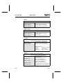
Festo Software Tools
Statement list and Ladder diagram for SF 3
FST 200 Manual
9610a
Only valid in agreement with the printed documentation
accompanying the product! Compare this edition code.
License agreement
License agreement
Festo’s conditions for the use of software packages
I. Proprietary rights and scope of use
The product contains data-processing programs and the associated product descriptions.
These in their entirety are referred to below as the "software package.
Festo or third parties hold proprietary rights in respect of these software packages. Festo has
acquired the appropriate licenses where these rights are held by third parties. Festo grants the
purchaser a license for use under the following conditions:
1. Scope of use
a) The software package may only be used on or in conjunction with one machine (i.e. one
computer with only one central processor unit and one VDU). This license is limited to the
execution of the software package on that machine.
b) Insofar as the packages are linked with other programs, these may also only be used on
one machine.
c) The programs supplied, and any programs associated with them, may be copied in machine-readable or printed form if the copy is intended for backup purposes. Clause 1a is also
applicable to copies.
d) Other forms of use, in particular reproduction for other purposes and passing the software
package on to third parties in contravention of the specifications of clause 3, or any modification or other type of use, are not permitted.
2. Copyright notice
Each program includes a copyright notice. This notice must be included in every copy, in all
edited versions and in every part of the program associated with other programs.
3. Transfer of license
The purchaser may transfer his license to a third party as a whole to the extent of and with
the restrictions on the conditions specified in clauses 1 and 2. The third party must be made
expressly aware of these conditions.
On transfer, the seller looses all rights to use the package, including all copies, edited versions and associated programs. These shall be destroyed if they are not transferred to the
third party.
4. Any conditions originating from other producers contained in this
software package are null and void.
II. Export of the software package
When exporting the software package, the licensee shall comply with the export regulations
of the Federal Republic of Germany and the country in which the software package was
acquired.
License agreement
III. Warranty
1. Festo guarantees that the software program it has produced complies with the application
description and the program specification, but not that the functions contained in the software
run completely without interruption or error or that the functions contained in the software
may be executed in all the combinations and operating conditions provided by the licensee,
or that they meet the licensee’s requirements.
2. Defects in the software notified by the licensee within the warranty period in a reproducible fashion will be rectified by Festo within a reasonable period to the exclusion of all further
claims against this warranty.
3. If Festo does not meet its obligation to rectify defects within a reasonable period, or if the
modification ultimately fails, the licensee is justified in requesting a reasonable reduction in
the licence fee or to cancel the contract.
4. The warranty period is 3 months and commences with the shipping or handover of the
licensed material.
5. The warranty is voided if defects are caused by modifications made by the licensee himself to the operating conditions prepared for the program and described in the documentation/functional specification. If the defect cannot be established, or if a malfunction is a consequence of circumstances for which Festo cannot be held responsible, the licensee shall be
held responsible for Festo’s costs.
IV. Liability/Limitations of liability
1. Claims for damages on the part of the licensee, and in particular liability for consequential
losses, are excluded, whatever the legal grounds; this applies for all claims relating to impracticality, non-fulfilment, positive breach of contract, tort and default.
2. Furthermore, Festo is not liable for inadequate economic results, or for losses incurred by or
claimed by third parties, with the exception of claims arising from infringement of a third party’s
proprietary rights.
3. The limitations on liability specified in paragraphs 1 and 2 do not apply in cases of malice
or gross negligence, or the absence of guaranteed features where compulsory liability applies. In cases of this nature, Festo’s liability is limited to those losses that were recognizable
to Festo on the basis of the situation at hand.
V. Safety guidelines/Documentation
Warranty and liability claims in accordance with the above specifications (clauses III and IV) are
valid only if the user has complied with the safety guidelines in the documentation in conjunction
with the use of the machine and the safety guidelines for this. The user is himself responsible for
ensuring the compatibility of our software package with the user’s machine.
FST 200
This manual and the associated software will allow the
user, familiar with the programming languages available, to write and modify control programs for programmable logic controllers. Furthermore, the program
package will allow him to execute various file operations, depending on the capabilities of the computer.
New users should also refer to the relevant basic manuals for the programming language concerned:
• Allocation list (STL)
Order no. 18352 GB
• Ladder diagram (LDR)
Order no. 18348 GB
Festo reserves the right to make modifications serving
technical progress.
Printed on 100% recycled paper
Authors:
S. Breuer, E. Klotz, R.Flick, H. Wilhelm
Editing:
H. J. Drung, M. Holder
Translation: Gerald Dennett
Layout:
FESTO KG, PV-IDM
Typesetting: Sturz, Berlin
Edition:
9610a
© Copyright by Festo KG, D-73734 Esslingen;
All rights, including translation rights, reserved. No part
of this publication may be reproduced in any form
(printing, copying, microfilm or any other method), or
processed, duplicated or distributed using electronic
means, without the written approval of Festo KG.
9610a
I
FST 200
Festo Software Tools
Allocation list and ladder diagram for the
programmable valve terminal with SF 3 control block
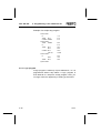
Order no.: ..........................................................165 489
Name:
.............................................FST 200 Manual
Designation...................... P.BE-FST200-AWL/KOP-GB
IBM®
registered trademark of
International Business Machines
Corporation
Microsoft®
registered trademark of
Microsoft Corporation
II
9610a
FST 200
Contents
Contents
1. Introduction
1.1
1.2
1.3
1.4
1.5
1.6
1.7
1.7.1
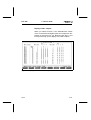
Contents of this software package ...........1-2
General explanation .................................1-2
How to use this manual ............................1-3
What PC do you need? ............................1-5
What connecting cable do you require? ..1-5
General key assignment ...........................1-6
Using a mouse...........................................1-9
Working with a mouse ............................1-10
2. Setting up the software
2.1
2.1.1
2.2
2.2.1
2.2.2
2.2.3
2.2.4
2.2.5
2.3
2.4
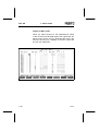
Installing the FST program ........................2-1
Installing on the hard disk ........................2-1
Configuring the FST program ...................2-5
Computer configuration ............................2-5
Controller configuration ..........................2-10
Selecting the printer type .......................2-12
Setting the printer control sequences ....2-13
Exit Configuration ...................................2-16
Starting the FST program .......................2-16
The FST 200 screen layout ....................2-18
3. Management of the control programs
3.1
3.2
3.3
3.4
3.5
3.6
3.6.1
9610a
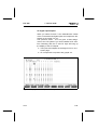
Create a project ........................................3-2
Select a project .........................................3-4
Delete project ...........................................3-6
Delete program .........................................3-8
Print a project ...........................................3-9
Print project parts ................................... 3-11
Print title page ........................................3-12
III
FST 200
Contents
3.6.2
3.6.3
3.6.4
3.6.5
3.6.6
3.7
3.8
3.8.1
3.9
3.10
3.10.1
3.10.2
3.11
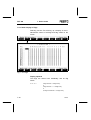
Print text document .................................3-12
Print allocation list ...................................3-12
Print program ...........................................3-12
Print cross-reference list .........................3-13
Print error list ..........................................3-15
Load project ............................................3-16
Backup/Restore (Project Backup) ..........3-18
Description of the functions ....................3-19
Import files ..............................................3-27
Calling a program ...................................3-36
Entering a program call ..........................3-37
Executing a program call .......................3-43
Linking a module ....................................3-44
4. Programming in allocation list (STL)
4.1
4.1.1
4.1.2
4.1.3
4.1.4
4.1.5
4.1.6
4.1.7
4.2
4.2.1
4.2.2
4.2.3
4.2.4
4.3
4.3.1
4.3.2
4.3.3
4.3.4
4.3.5
IV
General programming actions ..................4-4
Create a new program ..............................4-5
Select an existing program .......................4-8
The STL editor ..........................................4-9
Quit the STL editor...................................4-10
Additional instructions ..............................4-13
Editing commands ..................................4-15
Additional commands...............................4-17
Editing an STL program ..........................4-19
Step program ..........................................4-21
Logic program .........................................4-22
Execution statement ...............................4-24
Allocation listing entry during editing ......4-24
Functions in the STL editor ....................4-27
STL commands .......................................4-27
STL conditional statement ......................4-31
STL execution statement .........................4-34
Extended functions .................................4-36
Further instructions .................................4-40
9610a
FST 200
Contents
4.3.6
4.4
4.4.1
4.4.2
4.5
4.5.1
4.5.2
4.6
4.6.1
4.6.2
4.7
4.7.1
4.7.2
Indexed programming .............................4-42
Timers and counters ...............................4-43
Programming timers ...............................4-43
Programming counters ...........................4-48
Software modules ...................................4-54
Function modules (CFMnn) .....................4-54
Program modules (CMPnn).....................4-58
Allocation list ...........................................4-64
Allocation list entry during
program input .........................................4-67
Allocation list entry outside an
STL program ...........................................4-68
Status display .........................................4-75
Accessing the status display ..................4-76
Functions in the status display ...............4-78
5. Programming in ladder diagram (LDR)
5.1
5.1.1
5.1.2
5.1.3
5.1.4
5.2
5.2.1
5.2.2
5.3
5.3.1
5.3.2
5.3.3
5.3.4
5.3.5
5.3.6
9610a
Calling the LDR editor ...............................5-3
Create a new program...............................5-5
Select program ..........................................5-8
The working surface of the LDR editor ....5-9
File instructions .......................................5-10
Allocation list............................................5-12
Allocation list entry before
program input...........................................5-15
Allocation list entry during
program input...........................................5-22
Symbols for the LDR editor .....................5-24
Contacts...................................................5-29
Comparison boxes...................................5-36
Deleting conditional symbols ...................5-39
Parallel branches in the conditional part .5-41
Coils .........................................................5-45
Parallel branches in executive part .........5-47
V
FST 200
Contents
5.3.7
5.3.8
5.4
5.4.1
5.4.2
5.4.3
5.4.4
5.4.5
5.4.6
5.4.7
5.4.8
5.5
5.5.1
5.5.2
5.6
5.6.1
5.6.2
Jump command .......................................5-48
Boxes in the executive part .....................5-51
Defining a box in the executive part........5-52
Assignment ..............................................5-53
Timers ......................................................5-54
Counters...................................................5-63
Multibit operations in the executive part..5-69
Multibit operations with two operands .....5-70
Multibit operations with three operands...5-71
Arithmetic/logic.........................................5-72
Software modules ....................................5-76
Additional LDR editor functions ...............5-82
Block commands......................................5-83
Special operations ...................................5-86
Status display...........................................5-89
Accessing the status display ...................5-90
Functions in the status display ................5-91
6. Text editor
6.1
6.1.1
6.1.2
6.1.3
6.1.4
6.1.5
6.1.6
6.2
6.3
6.4
VI
Description and functions .........................6-2
Search commands ....................................6-4
Block commands ......................................6-8
Tab commands .......................................6-16
Additional commands...............................6-19
Editor help ...............................................6-21
File commands .......................................6-22
Define function keys ...............................6-22
Project title page .....................................6-29
Project page header ...............................6-32
9610a
FST 200
Contents
7. Dialogue and Online operation with the controller
7.1
Connection to the controller .....................7-2
7.2
Loading into the controller .........................7-3
7.2.1
Load project into the controller .................7-5
7.2.2
Load program into the controller ..............7-8
7.2.3
Save memory contents in the EEPROM ..7-9
7.3
Online Mode ...........................................7-15
7.3.1
Capability of Online Mode ......................7-19
7.4
Display SF3-INFO....................................7-22
7.4.1
Static display of the inputs and outputs .7-24
7.4.2
Static display of flags .............................7-30
7.4.3
Static display of the timers ....................7-31
7.4.4
Static display of the counters .................7-32
7.4.5
Static display of the registers .................7-33
7.4.6
Static display of error diagnostics ..........7-35
7.4.7
Static display of the system status .........7-38
7.5
Dynamic display .....................................7-39
7.6
Mini-Terminal ..........................................7-41
7.7
Using macros ..........................................7-42
7.7.1
Defining macros ......................................7-44
7.7.2
Running macros .....................................7-45
7.8
Terminal Mode ........................................7-47
7.9
System configuration
(set operating mode) ..............................7-48
7.9.1
Set Stand alone operating mode ...........7-49
7.9.2
Set Master and Slave operating mode ..7-50
7.10
Displaying the I/O configuration .............7-52
9610a
VII
FST 200
Contents
8. Field bus, AS-i Master, CP interface
8.1.
FST field bus configuration module ..........8-1
8.2
AS-i configuration module ......................8-13
8.2.1
Addressing the AS-i slaves .....................8-19
8.2.2
"SF 3 Online Mode" menu ......................8-21
Appendix A Statement list
A.1
A.1.1
A.1.2
A.1.3
A.2
A.3
A.4
A.4.1
A.4.2
A.4.3
A.5
A.6
Command set for the FST 200 STL ........ A-1
List of operations ...................................... A-2
List of operands ....................................... A-4
Syntax ...................................................... A-8
Multitasking operation for
programmable valve terminal with
control block SF 3..................................... A-9
Syntax of the control program in
the statement list..................................... A-10
Sample program ..................................... A-19
Structure of the control program............. A-19
Process control (P0) ............................... A-20
Monitoring program ................................ A-21
Allocation listing ..................................... A-22
Program listing ...................................... A-23
Appendix B Ladder diagram
B.1
Operations and operands in
FST 200 LDR ......................................... B-1
B.1.1
Operations of an LDR program ................ B-1
B.1.2
List of operands ...................................... B-10
B.1.3
Syntax for designation of
absolute operands .................................. B-13
B.2
Multitasking operation for
programmable valve terminal with
control block SF 3................................... B-14
B.3
Program example.................................... B-15
Appendix C
VIII
9610a
FST 200
Contents
C.1
C.2
C.3
C.3.1
C.3.2
Definition of terms ................................... C-1
Text editor command set .......................... C-5
Error messages ....................................... C-7
FST software messages........................... C-7
Controller messages .............................. C-40
Appendix D
D.1
D.2
D.3
D.4
9610a
Index of Diagrams .................................... D-1
Index of program modules and
function modules supplied (MAK-files) ..... D-6
Index ......................................................... D-8
Supplementary literature......................... D-19
IX
FST 200
X
Contents
9610a
FST 200
1. Introduction
1. Introduction
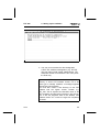
If you only consult this manual when confronted with
apparently unsolvable problems, you should at least
take time to read this page once.
1) Chapter 2 (Setting up the software) describes the installation, configuration and first use of the FST software.
If you wish to carry out an installation on a hard disk without the help of this manual, first insert Festo diskette #1
into your disk drive. Then switch to this disk drive
(e.g. A:). Enter:
FSTINS
and press the Enter key.
2) Connecting your PC to the controller is described in
Chapter 7 (Dialogue between PC and controller). This
chapter also explains how to load programs into your controller, and how to save a control program on an
EEPROM.
3) Chapter 7.3 (Online mode) is a brief introduction to
working "directly on the controller".
4) The Appendices include definitions of terms and list
and explain the complete command set. You will also find
detailed information regarding the complex functions here.
5) Refer to appendix C if you encounter any problems.
This lists the most frequently encountered error messages with brief explanations.
6) Appendix D is an index of keywords which will help
you find specific items.
9610a
1-1
FST 200
1.1
1. Introduction
Contents of this software package
A Festo FST software package contains:
• A user manual,
• Two 3.5" diskettes for the ladder diagram and
statement list program packages.
1.2
General explanation
FST stands for Festo Software Tools. This is the name
for programming software newly revised by Festo. The
FST 200 software package contains the FST 203 and
FST 202C program packages. The FST 200 is switchable so that it can also be used for older projects/programs, and allows programming in
• Statement list (STL)
• Ladder diagram (LDR)
The following controllers are supported
• SF 3 with the FST 203 program package
• FPC 202C / SB 202 / SF 202 with the FST 202C
program package
PLEASE NOTE
This manual contains a description of the FST 203 program package. A description of the FST 202C may be
found in older manuals (FST 202C, Statement list (STL)
for FPC 202C, Order no. 80 476; or FST 202C, Ladder
diagram for FPC 202C, Order no. 80 496)
Screen displays and operation in program input are
based on German standard DIN 19 239. In addition, the
controllers’ complete command set is fully supported.
This permits clear and structurally simple program representation.
1-2
9610a
FST 200
1. Introduction
Every software package supports the use of a mouse.
Most functions and inputs can be made by simply selecting with the mouse and then pressing a mouse button.
Context-related help is available from a help window
which may be called wherever you are in the program.
Symbolic operands:
An output need not necessarily have a designation
such as O5.3. It may just as well be assigned the symbolic operand MOTOR_ON. Symbolic operands can be
very helpful, especially in larger programs. Function
keys and selection menus make it easy to use the program and help in file management. These and general
editing functions are always used in the same way, as
far as possible. In some programs, you have the facility
to freely assign and label function keys.
1.3
How to use this manual
You can learn how to use the FST software by working
through all the chapters in order. It is best if you do not
just read the sections passively, but actively work
through the various actions.
You may also select individual sections you find of interest from the table of contents, thus constructing your
own personalized route through this manual.
The index of illustrations in Appendix D is an additional
aid. This shows all the screens used by the program.
Solutions to possible problems can be found very easily
in this way.
9610a
1-3
FST 200
1. Introduction
Lastly, with the help of the index, you can use this manual
as an FST software lexicon to find explanations of current
topics quickly.
We have included icons in the left-hand margin to help
you understand the text. The textual representations
listed below are used:
The arrow marks places at which the program expects
an input from you (e.g. A:FSTINS) outside the FST software.
The hand indicates especially important points in the
text. These should be read and noted.
The small mouse is an indication of points in the text
describing important details for the use of a mouse.
A superscript ® after a name indicates that this name is
a registered trademark (e.g. GridCase® computer).
Important instructions, explanations and comments
are printed in italics.
Possible sources of danger are shown in a frame.
1-4
9610a
FST 200
1.4
1. Introduction
What PC do you need?
The requirements listed below are based on the current
industry
standard.
You
will
need
an
IBM
PC/XT/AT/PS2® or another computer compatible with
these, with:
• Hard disk drive, and
1.4 MB floppy drive (3.5")
• The STL and LDR program packages require at
least 512 kB RAM; we recommend 640 kB for
larger projects.
• MS-DOS operating system version 3.0 or higher
• Monochrome or colour monitor and one of the following graphic cards:
-
Video Graphic Array (VGA)
Enhanced Graphic Adapter (EGA)
Color Graphic Adapter (CGA)
Monochrome card
Hercules Graphic Card (HGC)
or compatible
• Serial or better parallel interface for a printer
• Serial interface for connecting the controller
• If necessary, a second serial interface for a mouse.
1.5
What connecting cable do you require?
Recommendation:
Use one of the following ready-to-use Festo diagnostic
cables:
KDI-SB202-BU25
(25-pin socket for PC)
KDI-SB202-BU9
(9-pin socket for PC)
9610a
Part no. 30 437
Part no. 150 268
1-5
FST 200
9610a
1. Installing the software
1-5
FST 200
1.6
1. Installing the software
General key assignment
Particular care was taken in the development of the
FST programs to ensure that many keys always have
the same function. These will be described in this section.
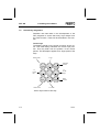
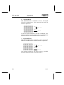
Cursor keys
The flashing pointer on the screen is known as the cursor. This mark always indicates the current input position. This may differ from the position of the mouse
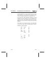
pointer. This description applies for a single press of the
keys.
Start of line
1 x up
Previous
screen
Home
Page
1x
to the
right
1x
to the
left
End
End of line
Page
Next
screen
1 x down
Cursor keys without CTRL key
1-6
9610a
FST 200
1. Installing the software
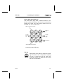
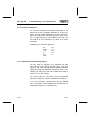
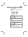
Cursor keys with CTRL key
The same cursor keys have a further function in conjunction with the CTRL key. This function is executed by
holding the CTRL key (see below) down and then
pressing one of the cursor keys.
Start of 1st line of screen
Home
Page
1 word
to the
left
Start of
file
1 word
to the
right
End
Page
End of file
Start of last line of screen
Cursor keys with CTRL key
Tab key
Each press of the tab key moves the cursor
right one field to the next position. Pressing
this key in conjunction with the SHIFT key
moves the cursor one field at a time to the
left to the next position.
9610a
1-7
FST 200
1. Installing the software
SCROLL LOCK key
Selecting this function and then pressing one
of the cursor keys moves the entire screen
Scroll
contents. You must press this key a second
time to deselect this function and revert to
the normal cursor control.
If the cursor cannot be moved, it is normally because
the SCROLL LOCK key is still activated.
ESC key
Esc
This key allows you to exit a selected action
without executing it. You are then returned to
your starting point.
ENTER key
(= Return, <cr>, Carriage Return key) This
key is used to conclude actions and selections, or to confirm inputs and activate functions.
DELETE key
This erases the character on which the curDEL
sor is currently located in text input. The cursor position remains the same.
1-8
9610a
FST 200
1. Installing the software
INSERT key
Use this key to insert characters from the
current position of the insertion mark. The
INS
Insert key enters a space at the current cursor position when you are entering data in
fields within the FST software.
BACKSPACE key
Each press of this key deletes the character
to the left of the cursor during text input. The
new cursor position is now one place to the
left. You can use this to correct input errors
before you complete by pressing the Enter
key.
CTRL key
CTRL
1.7
(=Control). This key is used to call extended
commands. These commands, known as
control commands, are principally required in
the text editor.
Using a mouse
All the functions you can activate using the cursor keys
and the ENTER key can also be achieved by positioning the mouse pointer and then pressing the left mouse
button.
These functions include for example:
• Selection and activation of any function in the
main menu and in the submenus based on this,
• Positioning at any position within the editors,
• Activating the inputs on the function keys,
• Scrolling the screen up and down (also left and
right in some editors).
9610a
1-9
FST 200
1. Installing the software
1.7.1 Working with a mouse
The FST software supports the left mouse button. This
means that the right mouse button has no function.
Please refer to the mouse operating instructions for installation of the mouse. This will also tell you which
driver software must be loaded for mouse operation
and how it is integrated into the operating system on
your computer.
When you are working with a mouse within the FST
software, you will see a bright rectangle on the screen.
You can move to the input position required by simply
moving the mouse.
Entering an entry field and activating it with the left
mouse button is known as Clicking on.
Mouse and the main menu
An entry you have clicked on in the main menu or in
the functions deriving from this is highlighted. This
means that it has been selected. Pressing the left
mouse button a second time executes or activates the
function referred to by the menu item.
1-10
9610a
FST 200
1. Installing the software
Mouse and function keys
Function keys F1 to F8 have different assignments, depending on which function is currently active. These assignments are not only the execution of other functions,
but can also be the input of program instructions (e.g.
allocation list, ladder diagram, text editor) within an editor.
Clicking on a field activates the corresponding action. If
you are currently working within an editor, the program
writes the input to the position selected in the working
area.
Mouse and editor
If you are currently working with one of the editors, you
can select the desired position with the mouse pointer.
This is significantly quicker and easier than using the
cursor keys.
Move the mouse cursor to the desired position in the
working area and press the left mouse button. You can
now begin editing at precisely this position. Naturally,
you can also use the fields in the function key bar (see
above).
Mouse and message window
Some message windows often also include queries as to
whether an action should be executed or cancelled.
These query fields are identified by [Y/N] or [ESC] fields.
Simply click on the appropriate field to respond.
Mouse and message line
Such queries often also appear in the message line. In
addition, in the online mode, for instance, the message
line also includes fields for executing special functions.
Here, too, you should click on the appropriate field to
activate the function or to respond.
9610a
1-11
FST 200
1. Installing the software
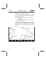
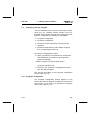
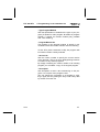
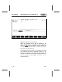
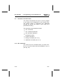
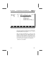
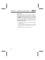
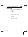
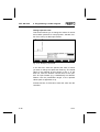
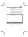
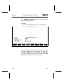
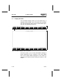
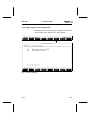
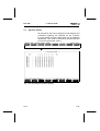
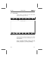
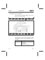
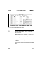
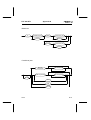
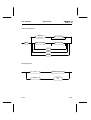
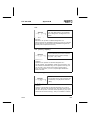
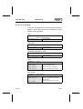
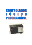
Scrolling the screen with the mouse
You can also use the mouse to execute the same effects as you can achieve with the cursor keys (see section 2.5). These include:
• Scrolling the screen content up and down within
the working area,
• In some editors, scrolling the screen left and right
within the working area.
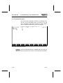
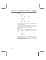
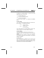
The various scroll functions are explained in the illustration below. Take care to position the mouse pointer precisely. In some cases, a difference of just one character’s width can cause a different function to be executed.
1 x click = top line of screen
then scroll downwards
Screen back
Start of file
Start of line
End of line
Scroll right
Scroll left
End of file
Screen forward
1 x click = bottom line of screen
then scroll upwards
Open the help window at any
position within the message
line.
Fig. 1.1: Scoll functions with the mouse
1-12
9610a
FST 200
2. Setting up the software
2. Setting up the software
2.1
Installing the FST program
Because of the significant capabilities of the Festo FST
software and the associated number of separate programs, you must install the FST software on the hard
disk.
Install FST 200 in its own subdirectory.
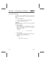
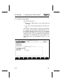
2.1.1 Installing on the hard disk
The installation program first creates the program directory (e.g. C:\FST) on the drive specified. The CONFIG.SYS file must contain the line FILES=18.
Next, all the program files for the FST software are copied to the program directory (e.g. C:\FST).
Your user programs will later be stored in the project
directory (e.g. C:\FESTO), collated into projects. Each
of these projects uses a further subdirectory there. You
must create the \LIB directory manually yourself (see
section 3.1). This stores all the subprograms and modules you save as macros.
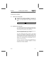
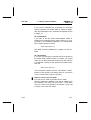
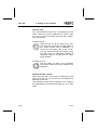
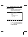
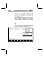
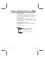
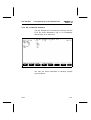
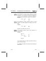
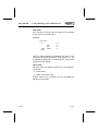
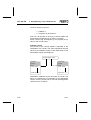
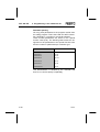
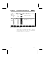
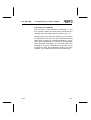
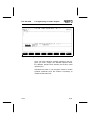
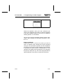
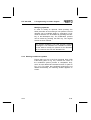
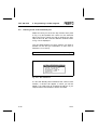
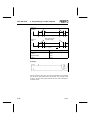
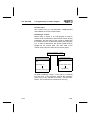
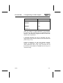
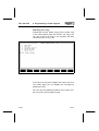
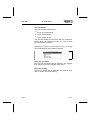
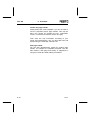
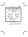
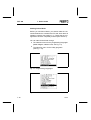
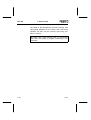
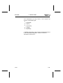
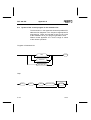
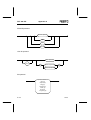
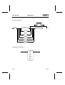
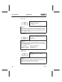
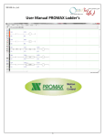
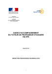
Figure 2.1 shows the structure of the subdirectories on
your hard disk after a successful installation. The drive
identifier has not been modified.
9610a
2-1
FST 200
2. Setting up the software
subdirectories
main directory
e.g.
project 1
project 2
others
etc.
Fig. 2.1: Organization on the hard disk (example)
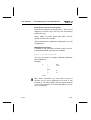
Installation procedure
• Switch on your Personal Computer and wait for the
operating system to load. This is indicated by the
C:> prompt.
• Now insert Festo program diskette #1 in your
floppy disk drive (e.g. drive A).
• Now change to the drive you are using (e.g. by entering A:) and press the Enter key. (This key is
generally identified with the symbol
.)
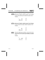
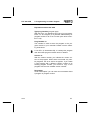
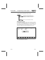
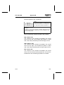
• Now enter FSTINS and press the Enter key again.
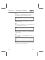
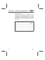
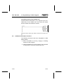
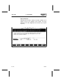
The following message appears on the screen
(see Fig. 2.2).
2-2
9610a
FST 200
2. Setting up the software
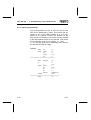
Fig. 2.2: Installation on hard disk
• You may now overwrite the drive designation
C:\FST with a different designation (e.g. E:\FST).
This may also include nested subdirectories. The
maximum number of characters is 36. Then press
the Enter key.
If you install FST software version 3.2 or higher in a
directory in which FST software version 3.0 of the
same type is already installed, a message appears
beneath the path indication.
You must then create a new directory for the FST
software with the higher version number, e.g.
FST_V32. This is required as otherwise some of the
FST programs will clash with programs in the old version. If the old programs were to be deleted, FST
software version 3.0 would no longer be completely
functional.
9610a
2-3
FST 200
2. Setting up the software
• Pressing the Enter key causes the various parts of
the program on diskette #1 to be copied to the directory specified immediately.
• Once the first diskette has been copied, you are
prompted to insert program diskette #2. Once you
have done this and confirmed with the Enter key,
these parts of the program will also be copied.
You will have to repeat this procedure a number of
times, depending on the extent of the software;
the diskette numbers will be indicated for you each
time.
• Once installation is successful, the program exits
to the operating system interface.
PLEASE NOTE
Install FST 200 in its own subdirectory.
No other FST packages may be located in the
same directory.
Program diskette #2 contains a large number of driver
programs in subdirectory \MAKLIB (see Appendix D.2).
These may be imported into the \LIB directory as required using File Import (see section 3.9).
2-4
9610a
FST 200
2.2
2. Setting up the software
Configuring the FST program
The FST software links a number of hardware components (e.g. PC, controller, printer). Entries in the configuration menu ensure that they are configured to work
together. Configuration is divided into four stages:
• Computer configuration
• Controller configuration
• Set printer control sequences (including printer
selection)
• Field bus configuration or AS-i Master configuration, if required (see section 8)
You enter the configuration routine,
• When you start the FST software for the first time
after installation (see section 2.3) and acknowledge the message:
Please configure FST project path <ESC>
by pressing the ESC key;
• Each time you activate the Configuration function
from the utility programs.
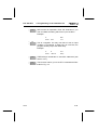
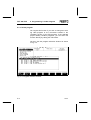
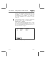
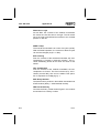
You are then first taken to the Computer configuration
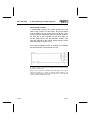
function (see Fig. 2.3).
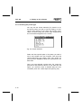
2.2.1 Computer configuration
The computer configuration window appears on the
screen after the FST program is started for the first time
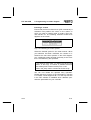
(see section 2.3) or when you activate the Configuration function (see Fig. 2.3).
9610a
2-5
FST 200
2. Setting up the software
Fig. 2.3: PC configuration data
You may overwrite the various entries once you have
positioned the cursor in the relevant field.
Press the INS key and type in the characters (insert
mode). Do not forget to press this key again afterwards
(overwrite mode).
You can delete superfluous characters with the DEL key
or with the backspace key (see section 2.5).
From here, use the function keys to switch to controller
configuration or to the screen for setting the printer control sequences and printer selection. In addition, function key F4 allows you to enter any program call (see
section 3.10).
2-6
9610a
FST 200
2. Setting up the software
Initialization
Here you can enter instructions to be executed immediately after the FST software is started. Such instructions might be:
• Any DOS command, e.g. setting the serial interface with the MODE command,
• A BATCH file (..... .BAT), but this may not activate
a memory-resident program,
• Any executable program.
Termination:
Here you can enter instructions to be executed before
the FST software is exited. Such instructions might be:
• Any DOS command, e.g. resetting the serial interface with the MODE command,
• Any executable programs.
• If you work with the memory-resident emulators, it
is useful to enter
EABG1N -u
as these emulators are then uninstalled when you
quit FST 200.
9610a
2-7
FST 200
2. Setting up the software
Comments on initialization and termination
You will need two serial interfaces if you wish to work with
a serial mouse. These must be defined as COM1 and
COM2.
If you use a serial mouse on COM1 or COM2, you must
ensure in all your other entries that this interface is excluded for use by other devices. Your serial interface must
always be active.
If you make a COM1 or COM2 serial interface exclusively available for the connection of the controller, you
should enter a DOS command in Initialization such as
MODE COM1:9600,N,8,1.
If you use the serial interface for the connection of the
controller for other tasks whilst you are using the FST
software (e.g. connection of a serial printer), you should
take this into consideration accordingly in the later controller configuration (see section 2.2.2).
Project directory
This entry contains the directory path. Here, your control programs are stored in the form of projects.
The default is the C:\FESTO directory. You can change
this default by overwriting it.
If the project directory specified does not exist on the
hard disk, it will be created automatically by the FST
software when you leave the configuration routine (see
section 2.2.5).
2-8
9610a
FST 200
2. Setting up the software
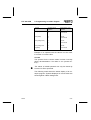
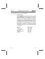
Screen adapter
E - Enhanced Graphic Adapter
V - Video Graphic Array
C - Color Graphic Adapter
H - Hercules Graphic Card and compatible
M - IBM monochrome card.
Monitor type
M - Monochrome monitor
F - Colour monitor.
Mouse type
M - Microsoft® mouse and compatibles
N - No mouse
If you have inadvertently entered incorrect data during
computer configuration, and the screen displays no information once you have completed configuration, you
must delete the file KONFIG.FST from the program directory at the DOS level. Do this with the command:
DEL KONFIG.FST
When you start the FST software again (see section
2.3), you will be taken back into the Computer configuration function.
9610a
2-9
FST 200
2. Setting up the software
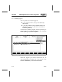
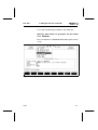
2.2.2 Controller configuration
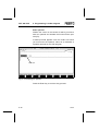
In the screen shown in Fig. 2.3 enter the controller configuration function by selecting FPC (F5). The following
screen image appears when you activate this function
(see Fig. 2.4)
Fig. 2.4: Controller configuration data
SF 3 interface
This parameter specifies the port on the computer to
which the controller is connected (COM1 or COM2),
and the baud rate at which data transmission is to take
place. Check that the controller is connected to the port
and is running at the baud rate specified. You can
change these defaults by overwriting them.
Section 7.3 describes how to connect your computer to
the controller correctly.
2-10
9610a
FST 200
2. Setting up the software
If you use the specified port exclusively for connection
with the controller, you should make no entries on initialization and termination in the controller configuration shown
in Figure 2.4.
SF 3 initialization
If you wish to use the same serial interface COM1 or
COM2 for the controller and for other devices (e.g. a serial printer or an EPROM programmer), you should enter
here a DOS command such as
MODE COM1:9600,N,8,1
This DOS command initializes the interface for the controller.
SF 3 termination
If you are connecting the controller and other devices to
the same serial interface COM1 or COM2, you should
enter here a DOS command ensuring that the interface
is configured correctly for the second connected device,
such as:
MODE COM1:2400,N,8,1.
This command ensures that the transmission characteristics of the interface are always reset on conclusion
of the communication with the controller.
Note for users of an FPC 202C
FST 200 can be used to program all FPC 202C
devices. Following installation, FST 200 is initially set to
FPC 203/SF3. You may use the function -> FST 202C
(F7) in the main menu (similar to that shown in Fig. 2.8)
to switch over to the FPC 202C.
9610a
2-11
FST 200
2. Setting up the software
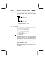
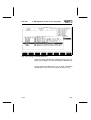
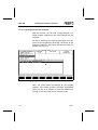
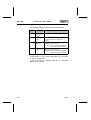
2.2.3 Selecting the printer type
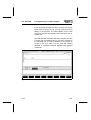
You may use the Printer selection (F1) function to select which printer you wish to use for printing, or to divert the print output to a file. When the function is activated, a window listing the printer types supported by
the FST software appears on the screen.
Fig. 2.5: Printer selection
Select the User specific option if the printer you wish to
use is not included in the list of options. Then enter the
control sequences your printer uses. The control sequences for the EPSON FX 80/81 are entered as the default value.
Once you have selected a printer type, the control sequences for that printer are shown. If you select the File
option, you must then enter a filename after the Communication port in the control sequences (see Fig. 2.6).
2-12
9610a
FST 200
2. Setting up the software
The printer control sequences for a printer will be saved
separately if you have modified them. You will then be
able to decide, when selecting a printer, whether you
wish to use the default control sequences or the modified control sequences for printing.
Please note the settings of the dip switches in the
printer. You should refer to the printer manual for these.
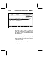
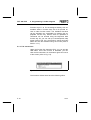
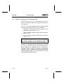
2.2.4 Setting the printer control sequences
Select function F2 if you wish to modify the printer control sequences. You will then see the following display.
Fig. 2.6: Printer control sequences
9610a
2-13
FST 200
2. Setting up the software
You will find the current printer type on the right of the
header line. You can modify the control characters by
overwriting the individual characters. The last line
defines the printer port.
Binding margin
You should remove the binding margin if you are printing out an STL program with comments. Do this by deleting with the Delete key all the spaces after the after
the Line feed and Carriage return characters (highlighted). Insert more spaces if you wish to have a wider
binding margin. This is done by pressing the Insert key
once and then the space bar several times. Do not forget to press the Insert key again afterwards.
Modifying control characters
You can overwrite the characters entered if your printer
requires characters other than those given as defaults.
After pressing the Insert key, enter the characters at the
current cursor position. Delete any superfluous characters with the Delete key. You must read your printer manual with regard to the modification of the printer commands.
2-14
9610a
FST 200
2. Setting up the software
Modifying special characters
You may enter other, equivalent characters if your
printer does not recognize the special characters entered. Open the help window by pressing F9 to do this.
If you page down through this help window, you will see
the ASCII code for the special characters.
Pressing the SCROLL LOCK key once allows you to
use the cursor keys to move these characters directly
over the listing on the screen.
If you now compare the characters entered with those
in your printer manual, you will be able to see which
characters, if any, your printer cannot understand. Now
enter different, equivalent characters instead of these
characters.
Do not forget to press the SCROLL LOCK key once
again when you have finished.
Communication port
After Communication port in the last line, enter the port
you intend to use for your printer (e.g. LPT1, LPT2,
PRN, COM1, COM2).
If you wish to use a serial mouse on COM1 or COM2,
you should note that this interface may not be used for
other devices.
9610a
2-15
FST 200
2. Setting up the software
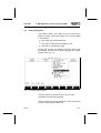
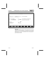
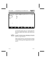
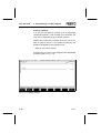
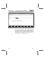
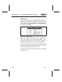
2.2.5 Exit Configuration
Exit the configuration routines by pressing function key
F8 or by selecting the corresponding option with the
mouse pointer and pressing the left mouse button.
Then select Save and quit editor from the file operations. You sould note that if you have changed the
screen adapter and the monitor type you will have to
quit the FST software by pressing F8 and completely
restart it.
2.3
Starting the FST program
The program can only be started if the appropriate
software has been correctly installed on the hard disk.
Calling the program
To start the FST software, change to the directory in
which you have installed the FST software, and enter
(for example):
C:\FST\FST200
and press the Enter key. The FST software will then be
loaded into RAM. If, when you press a key, the message appears:
Please configure FST project path [ESC].
pressing the ESC key will take you to the computer
configuration function (see section 2.2.1). You must first
enter the project path there.
2-16
9610a
FST 200
2. Setting up the software
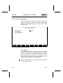
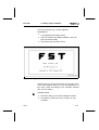
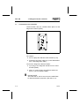
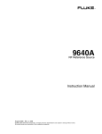
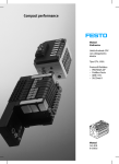
The FST logo (see Fig. 2.7) then appears
immediately if
• A configuration file already exists,
• There is sufficient free RAM available in the computer (at least 512 kB),
• The project path has been set up.
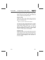
Fig. 2.7: FST logo
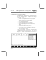
Pressing any key at this point brings up the main menu
of the FST software (see Fig. 2.8). The appearance of
this menu varies according to the controller selected
(SF 3 or FPC 202C).
PLEASE NOTE
• Check the setting of the FST software/controller.
• If necessary, press the F7 key to switch to your
controller.
9610a
2-17
FST 200
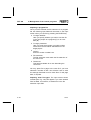
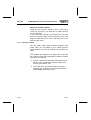
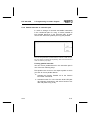
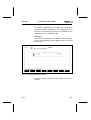
2.4
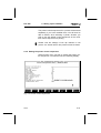
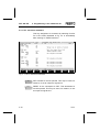
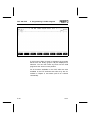
2. Setting up the software
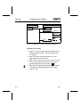
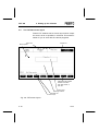
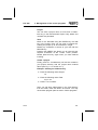
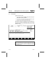
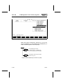
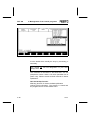
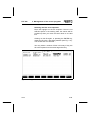
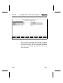
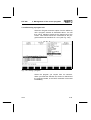
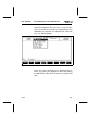
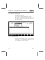
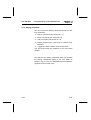
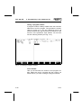
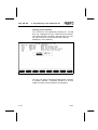
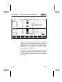
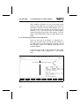
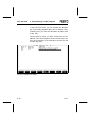
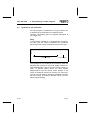
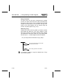
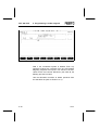
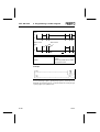
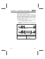
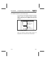
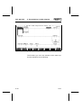
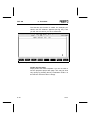
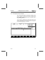
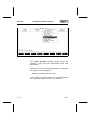
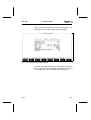
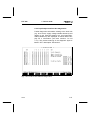
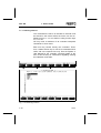
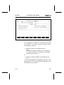
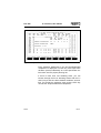
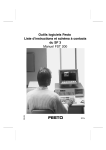
The FST 200 screen layout
Festo’s FST software has a screen layout which is kept
the same, as far as possible, in all areas. This makes it
easier for you to work with the various programs.
Menu title
Mouse pointer
Header line
Software can be switched
between FPC 202C /
FST 202C and SF 3 /
FST 203
Working area
Message window
Message line
Function keys
Fig. 2.8: FST screen layout
2-18
9610a
FST 200
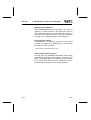
2. Setting up the software
Menu title
The current function of the FST software, e.g. online
mode, text editor, or similar, and the FST package
FST 203 or FST 202C installed is shown in the square
brackets.
Header line
You may call the menus available for selection here
• By selecting with the cursor keys and pressing the
Enter key
• By pressing the corresponding function keys
• By clicking on them with the mouse (see section 1.7).
Mouse pointer
The bright rectangle indicates the current position of the
mouse pointer on the screen. Moving the mouse moves
the pointer around the screen.
Working area
This field is the area in which you work. Here you enter
your programs or make your changes. This area has a
different appearance depending on what function is currently active.
Message window
Error messages will be displayed on a window with a
red background in the middle of the screen in the event
of an error.
Acknowledge these messages by pressing the Esc key
or by clicking on the [Esc] option within the window.
Message line
Special instructions relating to the screen input currently
required are displayed in this line.
9610a
2-19
FST 200
2. Setting up the software
Function keys
Your computer has function keys. The bottom line of the
screen shows the current assignment of function keys
F1 to F8. F9 and F10 always have the same assignment (see below).
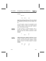
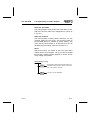
Function key F9
Press this key to call up Help at any time.
This help text will always be appropriate to
F9
the current function and is displayed in a
window at the bottom right of the screen.
You can browse through this window using
the cursor keys. An appropriate message is
displayed if there is no help text for a particular situation.
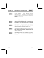
Function key F10
This key takes you back to the preceding
level when function keys have multi-level asF 10
signments.
Quitting the FST software
When, and only when, your screen is showing the main
menu, as in Fig. 2.8, you can quit the FST software by
selecting function F8.
The interfaces will be reset according to the configuration specifications and the DOS prompt (e.g. C:>) reappears.
2-20
9610a
FST 200
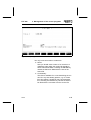
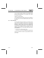
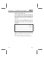
3. Management of the control programs
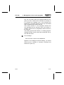
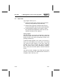
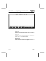
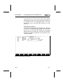
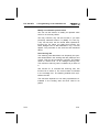
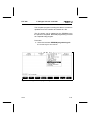
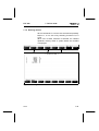
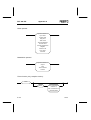
3. Management of the control programs
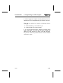
In addition to the editing of control programs (projects),
the FST software supports comprehensive management tasks. You can:
• Create new projects, or select existing projects,
• Delete individual programs or projects,
• Print out complete projects,
• Load complete projects to the controller,
• Save complete projects to an external storage
device,
• Import external files into the projects
• Link program modules and programs which you
may purchase from Festo.
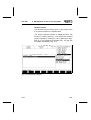
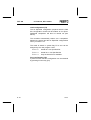
These procedures are accessed by selecting Project
management from the FST main menu. Here you will
be able to activate the appropriate function (see Fig.
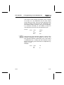
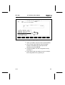
3.1).
Fig. 3.1: Project management
9610a
3-1
FST 200
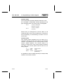
3.1
3. Management of the control programs
Create a project
You will have to create a project,
• When you start the FST software for the first time,
• If you wish to write a new control program (one
that does not already exist).
• If you wish to create the directory \LIB.
A project can contain a number of individual programs
which are collated to create a control program. You can
set up a title page, define a page header on every page
(see sections 6.3 and 6.4) and add text documentation.
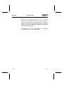
This function is started by selecting the Create project
function with the cursor keys or with the mouse pointer.
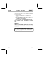
The following screen will appear if you now press the
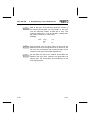
ENTER key or the left mouse button (see Fig. 3.2).
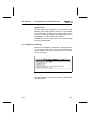
Fig. 3.2 Creating a project
3-2
9610a
FST 200
3. Management of the control programs
Project
You can enter a project name no more than 8 characters long in the field beneath Project. Only letters and
numbers are permitted.
Task
Move to the Task field using the ENTER key, the TAB
key or the mouse. Here you can enter a comment describing the project up to 40 characters in length.
Delete any characters in excess of your text with the
DELETE key.
Pressing the INSERT key allows you to insert all subsequent characters at the current cursor position.
Please press this key again when you have finished
inserting.
Create a project
Finally, press F1. A subdirectory will now be created in
your project directory with the project name entered
above (see Fig. 2.1 in section 2.1.1).
Example: Creating the \LIB directory
• Enter the following under Project:
LIB,
• Enter the following under Task:
Program files
• Press F1 to conclude.
Later you will store subprograms in the \LIB directory
from the editor, these are known as macros. You may
reuse these program parts or texts in further programs.
9610a
3-3
FST 200
3.2
3. Management of the control programs
Select a project
You will have to select a project,
• If you want to modify an existing program within
this project.
• If you wish to add a further program to the programs already existing within this project,
• If you wish to add further program modules to the
programs already existing within this project.
Select the Select project function from the screen illustrated in Figure 3.1 using the cursor keys or the mouse
pointer. The following screen will appear if you now
press the ENTER key or the left mouse button
(see Fig. 3.3).
3-4
9610a
FST 200
3. Management of the control programs
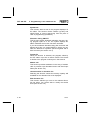
Fig. 3.3: Selecting a project
All existing projects are shown in the second window at
the bottom left of the screen. Select the project you
wish to work on by moving the highlight over the appropriate entry.
Pressing the ENTER key or clicking the left mouse button activates the project you have selected in the FST
software and brings up the main menu shown in Fig.
2.9 to the screen again. You can see that project selection has been successful as the name of the project
and its task is shown at the bottom left of the screen.
9610a
3-5
FST 200
3.3
3. Management of the control programs
Delete a project
You may delete a complete project (control program),
• If you no longer wish to work on a project for the
present,
• If you no longer require the project.
A project may include a number of individual programs,
program modules, the title page and text documentation. Remember that all of this will be removed when
you delete the project.
You should only delete a project if you are sure that
you will no longer require it, or that you have previously made a backup copy using the Project
Backup function. You can reload a project saved in
this way at a later date (see section 3.8.1).
Select the Delete project function to initiate the delete
procedure. The following screen (see Fig. 3.4) will then
appear.
3-6
9610a
FST 200
3. Management of the control programs
Fig. 3.4: Deleting a project
Select the project to be deleted in the second window
to the bottom left of the screen. Press the ENTER key
or the left mouse button to confirm. The confirmation
prompt will then appear:
Delete Project [Name].....<Y,N>.
yes
no
The entire project will be deleted with all
directory entries.
The program returns to the menu
shown in Fig 3.1.
All the files in the relevant subdirectory (except for
protected files) will be deleted when the project is
deleted.
9610a
3-7
FST 200
3.4
3. Management of the control programs
Delete program
You may delete an individual program,
• If you no longer need it, and you are absolutely
sure of this,
• If you have created a new, modified version of it
(see section 4.1.1/5.1.1) and this new version is
functioning perfectly.
To delete an individual program, select the Delete program function from Project management. The following
screen (see Fig. 3.5) will then appear.
Fig. 3.5: Deleting a program
Select the program you intend to delete from the second window at the bottom left of the screen. Then
press the ENTER key or the left mouse button.
3-8
9610a
FST 200
3. Management of the control programs
The following prompt will now appear in the message
line:
yes
no
The program is deleted from the current
project directory.
The program returns to the menu
shown in Fig. 3.1.
Delete Program [Name]..... <Y,N>
3.5
Print a project
This function causes a project to be printed in full. A
printout of this type always includes:
• The project title page (duplicate)
• All programs with page header
• The allocation list
• The cross-reference list
• The error list.
Depending on the size of your project, a complete printout including all the sections listed above could take
some time. This is because of the processing time required to generate the cross-reference list. Bear this in
mind when you request a printout of this nature.
Sections 3.6.1 to 3.6.7 explain how to print separate
parts of the list shown above.
Select the Print project function to print out a project
(see Fig. 3.6).
9610a
3-9
FST 200
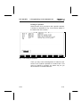
3. Management of the control programs
Fig. 3.6: Printing a project
You can now select from the programs listed the program you wish to print by clicking on it or placing the
highlight over it and pressing the ENTER key. Programs selected in this way are marked with an asterisk
at the start of the line.
Then select function F1. The program begins processing and subsequent printing. You can abort the printing
procedure at any time by pressing the ESC key.
First the project title page is output. Then the selection
you have made is printed.
Once printing is completed, the message line shows
Printing completed.
3-10
9610a
FST 200
3.6
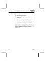
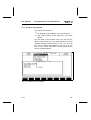
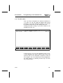
3. Management of the control programs
Print project parts
This function allows you easily to print out part of the
project currently active (see section 3.5). This is helpful
if, for instance,
• You need only the allocation list,
• You wish to view the cross-reference list,
• You wish to check a title page.
Access this function by selecting the Print option from
the Utilities. A further list of options appears in a further
window (see Fig. 3.7).
Fig. 3.7: Printing project parts
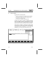
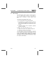
The print routine is started as soon as you have
selected the project part required.
You can abort the printing procedure at any time during
printing by pressing the ESC key.
9610a
3-11
FST 200
3. Management of the control programs
Please check the printer configuration (see section
2.2.3) if there are any differences between the printed
image and the screen display in one of the following
functions.
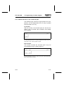
3.6.1 Print title page
When this function is selected, the project title page
prepared in the text editor is printed on the connected
printer.
3.6.2 Print text document
When this function is selected, the text document prepared in the text editor is printed on the connected
printer.
3.6.3 Print allocation list
When this function is selected, the allocation list belonging to the project is printed on the connected
printer.
3.6.4 Print program
Selecting this option initially brings up the same window
as is shown in Fig. 3.6.
You may now click on individual programs or select
them with the cursor keys and press the ENTER key.
The selected program is identified by an asterisk at the
start of the line. All programs marked in this way are
printed out when function F1 is selected.
3-12
9610a
FST 200
3. Management of the control programs
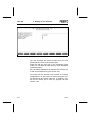
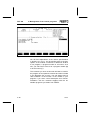
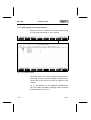
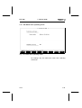
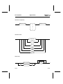
3.6.5 Print cross-reference list
When this option is selected, you will see a further window listing the operand groups. All the options are
marked with a leading asterisk (see Fig. 3.8).
Fig. 3.8: Cross-reference list options
The prefixed asterisk indicates that all operand groups
are active for the printout.
You may now select a group and prevent its processing
with the left mouse button or the ENTER key (the asterisk vanishes) or allow it again.
9610a
3-13
FST 200
3. Management of the control programs
Select function F1 when you have completed your selection. This starts cross-reference list processing. This
printout may take some time, depending on the size of
your project. The program has to check all entries in
the cross-reference list and print them properly formatted.
If you simply accept the complete default setting, you
will receive a printout containing all individual entries in
their full form. This can be done by pressing function
key F1 immediately.
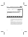
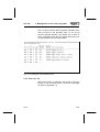
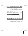
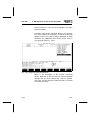
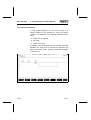
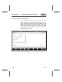
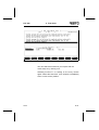
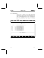
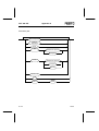
Explanation of the list
This list contains, in its first part, all the operands, ordered by absolute addresses (absolute operands).
Where the operands have a symbolic identifier and a
comment in the allocation list, this information is printed
out to the right of the operand. See Fig. 3.9.
3-14
9610a
FST 200
3. Management of the control programs
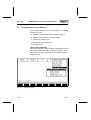
Part 2 of this list shows those symbolic operands which
were not found in the allocation lists, i.e. do not yet
have an absolute operand. This allows you a check on
which information must still be entered. Otherwise, your
control program will not be executable.
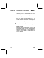
Fig. 3.9: Printing the cross-reference list
3.6.6 Print error list
When this function is selected, the current error list is
printed on the connected printer. These error messages
are listed in Appendix C.3.
9610a
3-15
FST 200
3.7
3. Management of the control programs
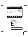
Load project
Use this function, when
• You wish to load a complete project with all its program parts into the controller,
• You wish to load several program parts from a project into the controller at the same time.
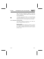
Start these routines by opening the Load project function from the Project management menu. All the program parts within the current project will then be listed
(see Fig. 3.10).
Fig. 3.10: Loading a project
Before loading a project into a controller, you must
make certain that the connection between the controller and your computer has been established correctly
(see section 6.1)
3-16
9610a
FST 200
3. Management of the control programs
You can now select from the programs listed the program you wish to load into the controller by clicking on
it or placing the highlight over it and pressing the
ENTER key. Programs selected in this way are marked
with an asterisk at the start of the line.
Then select function F1. The programs selected are
now translated into the machine code. This routine includes a syntax test; any irregularities will be entered in
the error list.
The loading process then follows. A "Loading program"
message window shows all the files transferred one by
one with their sizes.
If the message
FPC connection could not be established
appears in the message line before loading, you should
check that the controller is correctly connected and
switched on (see 2.2).
9610a
3-17
FST 200
3.8
3. Management of the control programs
Backup/Restore (Project Backup)
This function assists you in file handling for complete
projects. You can:
• Backup a project to an external storage device
• Restore a project from external storage
• Rename a project in full
• Delete a project completely
• Format disks.
Calling Project Backup
Open this function through project management. Here
you should select the Back up Project function. A window opens to allow selection of the various functions
(see Fig. 3.11).
Fig. 3.11: Project backup
3-18
9610a
FST 200
3. Management of the control programs
Open the function required by clicking on it with the
mouse or select the function with the cursor keys and
press the ENTER key.
The default target drive is drive A. You must first enter
a new drive designation if you wish to use the Project
Backup functions on another target drive (see below).
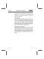
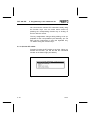
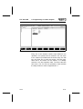
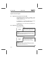
3.8.1 Description of the functions
This section explains the functions in the same sequence as they are shown in Fig. 3.11.
Back up project
This function is used to backup all the files of a project
to the target drive you have specified. A project selection window is displayed when this function is opened
(see Fig. 3.12).
9610a
3-19
FST 200
3. Management of the control programs
Fig. 3.12: Project selection, backup project
Select the project required by clicking on it or by placing the highlight on it and pressing the ENTER key. A
further window appears with the prompt:
yes
no
The message line shows:
"Project <Name> - please wait"
and the copying procedure begins.
The program returns to the status
shown in Fig 3.11.
Project will be backed up to drive A: (Y/N)
3-20
9610a
FST 200
3. Management of the control programs
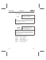
Restore project
Use this option to restore a project already saved to the
external storage device to the hard disk.
When you open this function, you first see the selection
window similar to that in Fig. 3.12. Here you can select
the project to be restored by clicking on it or by selecting it with the cursor keys and pressing the ENTER
key. A further window first appears with the prompt:
Project will be restored to drive
C:\FESTO\ (Y/N).
yes
no
The message line shows:
"Project <Name> - please wait"
and the program checks whether a
project with this name already exists on
the hard disk.
The program returns to the status
shown in Fig 3.11.
If the project is already on you hard disk, you will be
prompted:
Project will be overwritten! (Y/N) .
yes
no
9610a
The message line then displays the files
currently being processed. On
completion, the screen shown in Fig.
3.11 is displayed.
The program returns immediately to the
status shown in Fig 3.11.
3-21
FST 200
3. Management of the control programs
Delete project
This function may be used to delete a project stored on
the external storage device.
The project selection window is first displayed when
this function is opened (see Fig. 3.12). Select the relevant project required by clicking on it or by placing the
highlight on it and pressing the ENTER key. A window
appears with the prompt:
Project will be deleted from drive A: (Y/N).
yes
no
The message line shows:
"Project <Name> - please wait"
and the delete procedure begins. Then
the screen shown in Fig. 3.11 is
displayed.
The program returns immediately to the
status shown in Fig 3.11.
You can only use this function to delete projects stored
on the external storage device.
3-22
9610a
FST 200
3. Management of the control programs
Rename project
This function may be used to give a new project name
to a project stored on the external drive.
The project selection window is displayed when this
function is opened (see Fig. 3.12). Select the relevant
project required by clicking on it or by placing the highlight on it and pressing the ENTER key. You will see
the display illustrated in Fig. 3.13.
Fig. 3.13: Renaming a project
9610a
3-23
FST 200
3. Management of the control programs
You should now enter the new project name in the
small field in the message line (a maximum of eight
characters, digits and underline are also permitted) and
press the ENTER key.
The message line then displays the files currently being
renamed. When the procedure has been completed,
the function selection menu shown in Fig. 3.11 appears
again.
Target drive (A:, B:)
Use this function to change the identifier for the target
drive.
When this function is opened, an additional input field
appears in the message line as shown in Fig. 3.14.
Fig. 3.14: Changing a target drive
3-24
9610a
FST 200
3. Management of the control programs
You can now overwrite the default value (i.e. drive A) in
this field. The letters A to Z are accepted as input.
Then press the ENTER key.
However, this drive designation must be valid, i.e. the
drive specified must exist under this designation.
Note the drive designation for external mass storage
such as a streamer or removable 20 MB disk.
Format floppy disk
This function allows you to format disks in the specified
target drive using DOS Format at the DOS level (operating system), without leaving the FST software.
When this function is opened, drive A: is shown as the
target drive in a field in the message line
(see Fig. 3.15).
9610a
3-25
FST 200
3. Management of the control programs
Fig. 3.15: Formatting a floppy disk
A is the default drive. Modify the entry by overwriting, if
necessary.
You should not use the designation of your hard
disk(s) here.
The command is executed on the DOS level. You are
prompted to insert a disk in the drive specified and to
press a key. Please consult the DOS manual for further
explanation.
Quit the backup function
Selecting function F8 closes the Backup/Restore
routines (Project Backup). The window is closed and
the program returns to the Utilities menu.
3-26
9610a
FST 200
3.9
3. Management of the control programs
Import files
This program allows you to
• Restore programs from projects which have been
backed up using Backup (Project Backup)
• Restore other programs, allocation lists and project documentation that has been stored externally
• Load assembler programs and module or driver
files prepared and supplied by Festo into the LIB
directory and thence into a project.
Calling import
Call this function from project management. Select the
Import File option from this menu. You can quit the File
Import function at any point by selecting function F8 or
pressing the ESC key.
A window initially appears in the centre of the screen in
which you must specify the source drive. You should
now insert the data medium in this drive. Enter the
identifier for the drive required and press the ENTER
key. The source drive is then searched for subdirectories. These are the search paths in which the files are
stored.
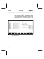
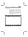
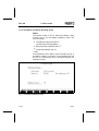
You will be shown a display of the files and the subdirectories. The names of the subdirectories are shown in
a brighter colour. See Fig. 3.16.
9610a
3-27
FST 200
3. Management of the control programs
Fig. 3.16: Search path selection
Select search path
Place the highlight on the search path required (lightcoloured entries). You can select the search path required by clicking on it again or pressing the ENTER
key. You will then get a display of the various files in
the subdirectory selected (see Fig. 3.17). Select the ".."
entry if you wish to switch back to the higher directory
level.
3-28
9610a
FST 200
3. Management of the control programs
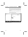
Selecting the files to be imported
Place the highlight on the file required. If there is not
sufficient space in the working area, the entries will be
scrolled up when you move the cursor down to the last
line.
Clicking on this file again, or pressing the ENTER key,
marks the file with a preceding asterisk (see Fig. 3.17).
This shows that it is selected.
You may select a number of files in this way if they are
all to be imported into the same target directory.
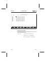
Fig. 3.17: File(s) selection
9610a
3-29
FST 200
3. Management of the control programs
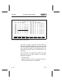
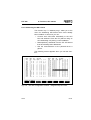
You may import files with the following extensions into
FST 200:
*.OBJ = loadable program
*.KOP = ladder diagram program
*.AWL = statement list program
*.BEL = allocation list
*.DOC = project documentation
*.ANZ = display files
*.MAK = drivers (can only be imported into the LIB
directory)
You can deselect a file by clicking on it again.
Conclude selection
Once you have marked the file required (or several
files) and are sure that your selection is complete, select function F1.
This concludes the selection of the program sources.
Now you need only select the target project and enter a
few details regarding the various files.
3-30
9610a
FST 200
3. Management of the control programs
Selection of the target project
The working area now displays the target project selection window. These are the projects which you have
created in the FST software (see Fig. 3.18).
Fig. 3.18: Target project selection
Here you should select the project directory into which
the files previously selected are to be imported. You will
then see the following input screen (see Fig. 3.19).
9610a
3-31
FST 200
3. Management of the control programs
File to be imported
Input fields (the new filename is
made up from these data)
Fig. 3.19: File information
File no.X
This field shows the title of the source file you have
selected. The new filename is composed of the settings
listed below. The file is transferred into the target project under this name.
3-32
9610a
FST 200
3. Management of the control programs
Settings
First enter the extension for the file in the file extension
input field. It must match the extension of the source file.
For instance, it is not possible to import an LDR file as
an STL file. When you confirm by pressing the ENTER
key, the input screen changes to show the file extension, according to whether you wish to import
• A program file (OBJ, AWL, KOP)
• Or another file type (BEL, DOC, ANZ, MAK).
9610a
3-33
FST 200
3. Management of the control programs
Importing a program file
Once you have entered the file extension for a program
file, the following input fields will be shown in the input
screen when you confirm by pressing the ENTER key:
• CI range identifier:
Here you specify whether you wish to use the file
in the new project as a program (P) or as a module (B).
• CI range parameter:
Here you enter the program or module number
under which the file will be administered in the
target project.
• Version:
Enter the version number here.
• File extension:
The file extension must match the file extension of
the source file.
• Comments:
This field is available for a note describing the
current file.
You may press F2 to page to the next file if you have
selected a number of files. You will also have to enter
the settings described here for these files. F3 will page
back, if required.
Importing other file types. The input screen shown
overleaf (see Fig. 3.20) will appear if you have entered
DOC or MAK, for instance, as extensions in the file
extension input field.
3-34
9610a
FST 200
3. Management of the control programs
Fig. 3.20: Importing a MAK file to the LIB directory
You only have two entries to make here.
• Name:
Here you should enter a name of no more than 8
characters under which the current file should be
saved. Recommendation: Pressing the ENTER key
causes the field to be filled with the name of the
source file.
• Commentary:
This field is available for a note describing the current file. Any text already present, e.g. for Festo
files (see above), should be kept. Recommendation: Pressing the ENTER key causes the field to
be filled with the comment from the source file.
9610a
3-35
FST 200
3. Management of the control programs
Transferring files
Once you have completed the settings for all the files to
be transferred, select function F1. The various files are
then transferred from the source drive to the project directory specified, in accordance with their numbering.
The FST main menu will reappear on the screen on
completion of the transfer.
3.10 Calling a program
This function allows you to call other, external programs
from within the FST software. You are returned to the
Utilities menu once the external program has run. Thus,
you do not need to quit the FST software if you require
external programs or wish to work at the DOS command level.
You have access to all kinds of external programs and
can
• Execute internal DOS commands (eg DIR*.OBJ)
• Switch over to the DOS level by calling
COMMAND.COM
• Call executable programs (these are programs with
one of the following extensions *.EXE, *.COM, *.BAT)
• Run FST programs which cannot be selected or
run through the FST menus.
3-36
9610a
FST 200
3. Management of the control programs
The last point is the principal application of this function.
Programs of this type are supplied with the FST software or will be available in future (e.g. position controller
with associated editor, display editor, etc). To make calling the program easier, the FST software supplies predefined parameters (#1 to #5) which you may combine
in any way you wish depending on the program call
required.
3.10.1 Entering a program call
You must first enter a program call before you can activate it. This is done by selecting the Configuration option from the utility programs. In this option you open
the Program call function.
You will then be presented with a dialogue box. The
first time you open this function you will only see a
highlighted field at the left margin. There may already
be entries when this function is called again. (See
Fig. 3.21).
9610a
3-37
FST 200
3. Management of the control programs
Fig. 3.21: Entering a program call
Here you enter the program call. The entry consists of
the filename and its extension. Executable programs
and DOS commands with the appropriate parameters
(see above) are permitted. No extension is required for
DOS commands.
3-38
9610a
FST 200
3. Management of the control programs
Working at the DOS level
Enter COMMAND.COM as the filename if you wish to
execute a number of tasks at the DOS level. This file
must previously have been copied into the directory in
which the FST software is stored. When this command
is called, your computer switches to the DOS level.
Directory/drive change
If the program to be called is not found in the current
directory, or resides on a different drive, you will have
to modify the entry as follows:
Drive:\subdirectory(ies)\filename.extension
Calling external FST programs
You may also use predefined parameters when calling
external FST programs. These allow you to assign the
same configuration data to the relevant program call as
the functions have within the FST software. Only then
will some external programs run without problem.
9610a
3-39
FST 200
3. Management of the control programs
The following tables show the possible parameters with
a description.
Parameter #1 (computer configuration)
#1
1st letter
Four character string describing
the PC configuration.
Identifies the graphics card:
E = EGA
C = CGA
H = Hercules card
V = VGA
2nd letter
Identifies the monitor type:
F = colour monitor
B = monochrome monitor
3rd letter
Identifies the computer type:
G = GridCase computer
N = all other IBM compatible types
4th letter
Shows use of a mouse:
M = MicroSoft Mouse or compatibles
N = no mouse
Example: EFNN.
Parameter #2 ( )
#2
Is not currently assigned
Parameter #3 (project and project path)
#3
String
Identifies the current project and its
path
Drive:\Path(s)\Project name
Example: C:\FESTO\FST 200.
3-40
9610a
FST 200
3. Management of the control programs
Parameter #4 (controller type)
#4
xxx
Identifies the controller type
101 = FPC 101
103 = FPC 103
203 = FPC 202 C
206 = SF 3
404 = FPC 404
405 = FPC 405
Example: 206.
Parameter #5 (port)
#5
COMx/y/z
Describes the interface parameters
x = 1 or 2 (serial)
y = baud rate
(300, 600, 1200, 2400, 4800, 9600)
z = wait time for response from controller
(0 to 32676 ms)
Example: COM1/9600/300.
A total of 38 characters are available for the program
call entry.
9610a
3-41
FST 200
3. Management of the control programs
Comment
Once your entry is complete, pressing the ENTER key
or the TAB key takes you to a new input field at the
right margin. You must enter a comment here. It describes the program to be called and will appear in the
selection window later when you open the Program execution function. The comment may be up to 36 characters long.
You may enter further program calls in the following
lines.
Quit function
Select function F8 to conclude the entry of program
calls. Then you will be given the options of
• Ending and quitting the function (entries will be
saved; the program returns to the main menu)
• Saving and continuing
• Cancelling the entry of program calls (the most
recent entries are discarded)
3-42
9610a
FST 200
3. Management of the control programs
3.10.2 Executing a program call
Select the Program execution option from the utilities to
call a program entered as described above. You will
then see a selection window at the bottom left of the
screen. This window shows the comments for the programs entered as described in 3.10.1 (see Fig. 3.22).
Fig. 3.22: Calling a program
Select the program you require from its comment.
When you make the selection the screen is cleared and
the program loaded, or the DOS command is executed
immediately.
9610a
3-43
FST 200
3. Management of the control programs
Return to the FST software
Press any key (except: Function keys, cursor keys,
CTRL key, ALT key) if you wish then to switch back to
the FST software.
If you have been working at the DOS level, you must
enter the command EXIT and then press any key. If the
program called returns an EXIT code=255, you do not
need to press a key.
3.11 Linking a module
You can obtain ready made machine programs from
Festo which you can adapt to your control program.
These modules can then be used like your function modules.
The modules are supplied on a floppy disk. A description of their functions and operands is attached. Further
procedure is as follows:
• Insert the disk in the disk drive and import the modules into the \LIB directory using the Import file
function (see section 3.9).
• Then open the Link module option from Project
management. A picklist of the modules imported
will be displayed (see Fig. 3.23).
3-44
9610a
FST 200
3. Management of the control programs
Fig. 3.23: Linking a module (selection)
Open the option required by double-clicking on it or by
placing the highlight on it and pressing the ENTER key.
First a window will appear for you to enter information
regarding the use of the new module (see Fig. 3.24).
9610a
3-45
FST 200
3. Management of the control programs
Fig. 3.24: Module information
You will find explanations of the various specifications
in sections 4.1.1/5.1.1. You should first refer to the description of the module concerned to determine whether
it is a program, a program module or a function. As a
rule, you will have to save it as a program module (B)
or as a function (F).
The comment you enter under task will later be used in
the program as an operand comment and also included
in the allocation list as such. You will always have a
clear indication of the function of the module in your
program if you enter a brief descriptive text. Recommendation: Use the comment supplied with the assembler programs you obtain from FESTO.
3-46
9610a
FST 200
3. Management of the control programs
Select function F1 once all the information has been
entered correctly.
A module uses certain operands. Refer to the description of the module for information. A further window will
appear in which you need to assign addresses to these
operands; the addresses must match those used in
your program (see Fig. 3.25).
Fig. 3.25: Assigning operand addresses
Refer to the description of the module concerned
(driver, MAK file) to find out how the various operands
operate and for which values they must be queried.
Only then will the relevant module be able to execute
its function precisely.
9610a
3-47
FST 200
3. Management of the control programs
Example (see above):
The module uses two flags. The default entries are
M 00.00 in each case.
• Enter the flags which are to be used.
• Allocate different flags. Otherwise you will have incorrect entries in the allocation list.
Specify the content of the flags in your control program.
Select function F1 once all the information has been
entered correctly. The module will now be modified to
your control program and linked into the project concerned. You can now call the module like a program
module or a function.
3-48
9610a
FST 200
3. Management of the control programs
Once a module has been linked, its data and the parameters used are entered in the error list. You can view
these entries using the Show error list function from the
selection menu of the relevant programming language. An
example is shown below.
---------------------------------------------------[ Error list V3.2 ]--------------------------------------------Filename : B0.10 V1
Object module
: ABG display driver, internal texts
=======================================================================
Source file(s)
: C:\FST\SF3\PROJEKTE\LIB\3FD_XABG.MAK
Object file
: C:\FST\SF3\PROJEKTE\HAUSTEL2\3Z0B10V1.OBJ
FPC Type
: FPC SF3
Code type
: CMP
Object code generated
: 155 bytes
Operands used
:
Absolute operand Symbolic operand Comment
=======================================================================
M0.0
Var_Ausgb
Representation style for values (VZ)
M0.1
Busy
Text output active
Entries marked with an asterisk (*) could not be
included in the allocation list.
-----------------------------------------------------------------------------------------------------------------------------
9610a
3-49
FST 200
3-50
3. Management of the control programs
9610a
FST 200-STL
4. Programming in the statement list
4. Programming in statement list (STL)
You can write control programs for the Festo SF 3 controller with the help of the statement list. A user-friendly
editor helps you in the creation of your programs and a
further tool checks them for syntactical correctness.
The STL programming menu allows you
• To write and edit user programs and program modules in the statement list
• Freely modify the assignment of the STL function
keys as you wish
• Check an STL program for syntactically correct
entries
• Load a single STL program into the connected
controller
• Print out a single STL program
• View an error list containing possible errors in the
STL program
• Trace the execution of an STL program in the controller (status display)
• Connect the computer to the controller through
FPC Online Mode (see chapter 7).
9610a
4-1
FST 200-STL
4. Programming in the statement list
The number of resources you may enter, i.e. inputs,
outputs, flags, etc., in brief, the operands and their addresses, is dependent on the type of controller you
have. The list in appendix A.1.2 shows which operands
are suitable for the controller used.
You may enter these operands in a control program in
two ways; as
• Absolute operands (e.g.: O2.7)
• Symbolic operands (e.g.: MOTOR_ON).
A program in which you use only absolute operands is
immediately executable. Your program will be easier to
read and understand if you use symbolic operands. You
will then, however, also have to specify the absolute
operands in the allocation list.
Naturally, you may also create the allocation list first.
You will access these entries when subsequently entering the program.
4-2
9610a
FST 200-STL
4. Programming in the statement list
Select the Statement list menu item in the FST main
menu to access the functions for programming in the
statement list. A window, the statement list menu (see
Fig. 4.1), will then appear.
Fig. 4.1: Statement list menu
Open the options required here by double-clicking on
them or by placing the highlight on them and pressing
the ENTER key. This action is valid for all inputs of this
type.
9610a
4-3
FST 200-STL
4.1
4. Programming in the statement list
General programming actions
A statement list program must be part of a project (see
section 3.1). The FST software identifies it by
• Its CCU number (a number of central control unit,
always 0 on the SF 3)
• Its program number
• Its version number
• And its association to a project.
This means that you must always first create a project
(see section 3.1) for your control program before you
enter the first part of it (allocation list, title page or
statement list program). Later it will be sufficient to select the corresponding project (see section 3.2). The
project name will be displayed at the bottom left of the
working area.
Select the STL editor function from the Statement list
menu (see Fig. 4.1) if you wish to enter a statement list
program for this project. There are two possibilities for
further procedure:
• The active project does not yet contain any programs
(see section 4.1.1)
• The active project already contains programs (see
section 4.1.2)
4-4
9610a
FST 200-STL
4. Programming in the statement list
4.1.1 Create a new program
You require this function if
• No program is yet available in the active project
• You wish to add a further program to the active
project.
You are taken to this function when you call the STL
editor for the first time or if you select function F1 in the
program selection window shown in Fig. 4.3. You will
then see a window as illustrated in Fig. 4.2. The window on your screen may differ in some details as this
view is controller-specific.
Fig. 4.2: Creating a new program
9610a
4-5
FST 200-STL
4. Programming in the statement list
Program parameters are already entered in this window
as default values. You can modify these parameters by
overwriting the characters. Delete any superfluous characters with the DELETE key.
Once all the information is correct, you can create the
program by selecting function F1.
The permitted input is shown in the following table:
Input
SF 3
Type Program/Module
P/B/F
Program/Module No.
0 to 15
Function No.
(only for "Link module")
4-6
90 to 99
Version no.
1 to 9
Description
Text
9610a
FST 200-STL
4. Programming in the statement list
- Type Program/Module
Use this specification to determine the type of your program (P stands for main program; B stands for program
module; F stands for function module [only possible
with "Link module"]).
- Program/Module No.
The program or the program module is stored in your
controller under this number. Please note the following.
On the SF 3 (when Automode is ON), the program with
the lowest number is always started.
- Version No.
Use the version number to specify the current version
of the program. This is an aid to distinguishing between
a number of very similar programs.
By simply increasing the version number of an existing
program you will obtain a copy of the original program.
- Description
Use description to enter a text commenting on the program. It is not part of the program name.
You can change the comments on a program by creating it again, but only editing the entry under Carry data
by means of function F2.
9610a
4-7
FST 200-STL
4. Programming in the statement list
4.1.2 Select an existing program
You require this function if
• You wish to modify an existing STL program.
You are taken directly to this function when you call the
STL editor, if the active project already contains programs (see Fig. 4.3).
Fig. 4.3: Selecting a program
Select a program by double-clicking on it or by placing
the highlight on it and pressing the ENTER key. It is
then loaded directly into the STL editor.
4-8
9610a
FST 200-STL
4. Programming in the statement list
4.1.3 The STL editor
Once you have concluded the functions described in
4.1.1 and 4.1.2, the STL editor will appear after a brief
load time. If you have selected a program, you will see
the relevant entries for it in the working area. The
working area will be empty if you have created a new
program (see Fig. 4.4).
Fig. 4.4: STL editor
Function keys F1 to F8 in the illustration shown in Fig.
4.4 are assigned with calls to further levels. There you
will find most of the instructions required to write an
STL program. You can switch back to key assignment,
as shown above, by pressing function key F10 from
any of these levels.
9610a
4-9
FST 200-STL
4. Programming in the statement list
You can enter the various STL instructions easily using
the function keys. You can make these entries by
pressing the corresponding function key or clicking on
the box with the mouse.
The key assignments change during editing to be appropriate for the next possible input. Naturally, you can
also type the instructions in using the keyboard only,
i.e. without using the function keys.
4.1.4 Quit the STL editor
Function F8 quits the STL editor at any time. When you
activate this function, you will see the file commands
window at the bottom right (see below).
Fig. 4.5: File commands
4-10
9610a
FST 200-STL
4. Programming in the statement list
Save and quit editor
The STL program is saved in the project directory. The
system then quits the STL editor. The FST main menu
as shown in Fig. 2.8 then reappears on the screen.
Save and continue
The STL program is simply saved. But it remains
loaded in the editor. You can then continue to edit at
the last position.
Abort (discard and quit editor)
If you select this option, a further window appears with
the prompt
Are you sure? (Y/N).
yes
no
9610a
The changes made since the last
backup are discarded and the program
returns to the FST main menu as
shown in Fig. 2.8.
You are returned to the STL editor.
4-11
FST 200-STL
4. Programming in the statement list
Read text block
If you require a block saved in the \LIB directory at the
current input position, you can load the block at this
point using this function. It is inserted at this point.
Please refer to section 6.1.2 for further details regarding
block commands. The creation of blocks is also described there.
Write (save) text block
You can save on disk a program section you might require repeatedly with this function, as long as you have
first marked it with the block commands. It will then be
saved to the \LIB directory
(see section 3.2).
4-12
9610a
FST 200-STL
4. Programming in the statement list
4.1.5 Additional instructions
Function keys
In total, you have a maximum of ten levels, each with
eight function keys (F1 to F8), available to you in the
FST software. You can modify the assignment of these
function keys as you wish using the STL function keys
function. This is done as follows:
• Select the STL function keys function.
• The function key editor will show you the first three
of the assigned levels.
Please refer to section 6.2 for instructions on how to
modify the entries.
CTRL commands
The STL editor provides you with editing tools in the
form of CTRL commands (see appendix C.2). Furthermore there are some additional commands particular to
this editor.
CTRL-B
This command toggles automatic allocation list entry on
and off. If this option is selected, you will be able to
make an entry in the allocation list each time you complete a line by pressing the ENTER key.
CTRL-O-B
This command switches over to the selection of additional commands. Refer to section 4.1.7 for these commands.
9610a
4-13
FST 200-STL
4. Programming in the statement list
CTRL-O-F
This command gives the current STL program a uniform format. This formatting gives your program a structure that is easier to read.
CTRL-O-L
This command calls the allocation list editor.
CTRL-O-G
This command calls the allocation list editor.
CTRL-O-V
This command opens a window in which you can specify the parameters for a module call. Refer to sec-tion
4.5. for these commands.
CTRL-V-A
This instruction calls the syntax test. Your program will
then be checked for formal correctness.
You will be notified by an appropriate message at the
end of the test if the test finds an error. The following
message will appear if your program is formally correct:
No errors found [assigned key].
4-14
9610a
FST 200-STL
4. Programming in the statement list
4.1.6 Editing commands
You can access the following functions through the editing commands:
• Search commands (see section 6.1.1)
• Block commands (see section 6.1.2)
• Tab commands (see section 6.1.3)
• Delete program lines, insert lines or restore modified lines
• Toggle the cursor between a line and a block.
The first three items are explained in the Text editor
chapter.
You switch to the editing commands when you activate
the Editing commands option in the STL editor as
shown in Fig. 4.4. Fig. 4.6 illustrates the associated assignment of the function keys.
9610a
4-15
FST 200-STL
4. Programming in the statement list
Fig. 4.6: Editing commands
Insert line
Selecting this function once causes a line to be inserted
before the line in which the insertion mark is located.
Delete line
Selecting this function causes the line in which the insertion mark is located to be deleted.
Restore line
Select this function if you have modified the content of
a line, but wish to restore it to its original state.
4-16
9610a
FST 200-STL
4. Programming in the statement list
Toggle cursor
You can change the appearance of the insertion mark.
Normally, the insertion mark is shown as a line beneath
the text character. Activating this function causes it to be
shown as a flashing rectangle. This appearance gives a
better display on some monochrome monitors.
Selecting the function again returns the insertion mark
to its line representation.
4.1.7 Additional commands
Switch to the additional commands by selecting function
F7 in the STL editor (see Fig. 4.4). The Additional commands window will then be displayed at the bottom
right of the screen.
Fig. 4.7: Additional commands
You may select the various menu items by the methods
described above.
9610a
4-17
FST 200-STL
4. Programming in the statement list
Syntax test
This function starts a test of the program displayed in
the editor. The function checks notation (syntax) and
simple forms of correct sequencing from the point of
view of programming (semantics).
Allocation listing ON/OFF
This function toggles automatic allocation list entry during program input on or off. The system displays the
status valid after the function has been activated.
If you have selected Allocation listing ON, a window will
appear each time you press ENTER in which you can
enter the absolute or symbolic operand together with a
brief comment (see section 4.2.4).
Format file
When this function is selected, the program called by
the STL editor is put into a uniform format. This format
is similar to the program code layout in this manual.
Module call
This function provides assistance in the entry of module
calls. It provides a pre-formatted screen with fixed input
fields (see section 4.5).
Unused entries in allocation list
Selecting this function causes the memory capacity still
available for the allocation list to be displayed.
Edit allocation list
This function switches you over to the relevant allocation list editor. You will be able to modify the entries
there (see section 4.6).
4-18
9610a
FST 200-STL
4.2
4. Programming in the statement list
Editing an STL program
At this point, we repeat all the steps you will have to
carry out to access the STL editor.
• Create a project or select an existing project in project management.
• Activate the STL editor in the screen illustrated in
Fig. 4.1.
• Select an existing program or create a new program.
• The STL editor now appears and you can write a
program or edit an existing program.
The various instructions, with the exception of the operands, can be entered easily using the preset function
keys or typed in from the keyboard.
General program structure
A control program in STL is composed of a number of
instructions. Consider the following short program for instance:
STEP <Label>
IF
AND
THEN
SET
OTHRW SET
...
Switch1
I1.1
O1.0
Horn
Each separate line represents one instruction for the
controller.
9610a
4-19
FST 200-STL
4. Programming in the statement list
An instruction of this type is composed of:
• STL commands (IF, AND, THEN, SET, OTHRW)
• Specific function units such as inputs or outputs
(known as operands)
• Their addresses (1.0, 1.1) The addresses indicate
which input or output on which I/O module should
be addressed. In the example described above,
this means:
I1.1 is input 1 on I/O module 1
O1.0 is output 0 on I/O module 1
Switch1 and Horn are symbolic operands.
When you enter a program, you must always make
sure that you write the operands and their related addresses together. They may never be separated by a
space.
The full structure and syntax of an STL program is
shown in appendix A.3.
When entering a new program, you may write it as:
• A step program
• A logic program
• An execution statement.
4-20
9610a
FST 200-STL
4. Programming in the statement list
4.2.1 Step program
A step program can contain up to 255 steps (1...255).
You may label each step with a symbolic step label.
The steps will be numbered consecutively when the
program is compiled if they are not already labelled in
this way.
You can use branching in a step program (JMP TO step
label). This causes your program to be continued with a
step other than that immediately following.
A step consists of one or more statements. A complete
statement contains an IF statement, a THEN statement
and possibly an OTHRW statement.
The first statement in each step may be an incomplete
statement. This would be a pure execution statement
(THEN...). This THEN statement is always executed
without an input condition.
The program is executed step by step. A subseqent
step will only be executed if it has been possible to
execute a THEN or OTHRW instruction in the last
statement of the current step.
9610a
4-21
FST 200-STL
4. Programming in the statement list
Example of a simple step program:
STEP Label1
IF
THEN
SET
OTHRW RESET
STEP Label2
THEN
RESET
IF
THEN
SET
SET
OTHRW SET
JMP TO
STEP Label3
IF
AND
THEN
SET
STEP Label4
...
I1.0
F1.5
F1.5
F0.0
F1.5
O0.7
F0.0
O0.0
Label1
F0.0
I0.0
O0.4
4.2.2 Logic program
A logic program is made up of pure statements, i.e. it is
programmed without step labels. A logic program is
thus identical to a step from a step program. Here, you
no longer have the opportunity of setting up branches.
4-22
9610a
FST 200-STL
4. Programming in the statement list
The first statement in a logic program can be an incomplete statement. You must write all subsequent statements as complete statements (see appendix A.3).
You must enter a PSE (processor interrupt) in the last
statement if the logic program is to be processed in any
number of cycles. This statement will have to be structured in such a way that this processor interrupt always
happens.
The program is processed cyclically. The THEN statement for which the condition is fulfilled will be executed.
Example of a logic program:
THEN
IF
THEN
IF
THEN
OTHRW
RESET
N
SET
SET
SET
RESET
...
...
IF
THEN
OTHRW
9610a
AND
SET
PSE
PSE
F0.0
I1.0
O0.7
I1.7
O1.7
F0.0
O1.7
F0.0
I1.0
O1.0
4-23
FST 200-STL
4. Programming in the statement list
4.2.3 Execution statement
An execution statement is basically structured in the
same way as an incomplete statement in a logic program. The first THEN statement is omitted. Here all instructions entered are executed without an input condition. A program branch is not possible in this case. You
will receive an error message if you enter an IF statement later.
Example of an execution statement:
SET
RESET
LOAD
TO
SET
CMP2
...
F0.0
O1.0
V50
TW7
T7
4.2.4 Allocation list entry during editing
You can enter the operand in an allocation list after
each carriage return during program input. To do this,
however, you must previously have selected Allocation
listing ON under the additional commands. This is indicated by an entry to the left of the header line. Refer to
section 4.6.1 in this respect.
You cannot make an entry here if you have selected
Allocation listing OFF under the additional commands.
If you now conclude a program line with the ENTER
key, the program checks whether the operand has already been entered in an allocation list.
4-24
9610a
FST 200-STL
4. Programming in the statement list
There are three possibilities here:
• Operand has already been entered
• Absolute operand not entered
• Symbolic operand not entered.
Operand has already been entered
When you complete the line with the ENTER key, the
current program line is quit immediately and the cursor
placed on the next input line.
Absolute operand is not entered
When you complete the line with the ENTER key, first a
further dialogue box is opened. Here you are able to
enter a symbolic operand identifier for the absolute
operand designation (see Fig. 4.8). The operand will be
included in the allocation list when you complete your
input by selecting function F1. Selecting F8 or pressing
the ESC key means that the entry is not executed. The
absolute operand, however, is retained in the STL program.
9610a
4-25
FST 200-STL
4. Programming in the statement list
Fig. 4.8: Entering an absolute operand
Symbolic operand is not entered
When you complete the line with the ENTER key, the
same dialogue box as that shown in Fig. 4.8 opens.
Here you must enter an absolute operand identifier for
the symbolic operand identifier. Only then will an entry
be made in the allocation list.
The operand will be included in the allocation list when
you complete your input by selecting function F1. Selecting F8 or pressing the ESC key means that the
entry is not executed. The symbolic operand remains in
your STL program; your program is, however, not executable like this.
4-26
9610a
FST 200-STL
4.3
4. Programming in the statement list
Functions in the STL editor
This section will describe the input in an STL program
on the basis of the assignment of the function keys.
The various groups of instructions are distributed
amongst the function key levels in such a way as to
permit fluent working.
The instructions are grouped as follows:
• STL commands
• STL conditional statement
• STL execution statement
• Extended functions
• Further instructions
• Editing commands (see 4.1.6)
• Additional commands (see 4.1.7)
4.3.1 STL commands
You access the STL commands when you select function F1 in the STL Editor menu as illustrated in Fig. 4.4
(see Fig. 4.9).
9610a
4-27
FST 200-STL
4. Programming in the statement list
Fig. 4.9: STL commands
The descriptions below apply for a single implementation of the corresponding function. The instruction entered will be written on the screen at the current cursor
position.
F
1
Step
The STEP instruction is very important for sequencing
programs, as this specifies the structure or the sequence for program branches.
STEP must be followed by a step label with a maximum
of nine characters or a number. It is required if you wish
to branch to this step from a different point in the STL
program.
4-28
9610a
FST 200-STL
4. Programming in the statement list
Example:
STEP Setup
...
...
THEN
JMP TO
Setup
During the compile procedure the steps are numbered
again internally counting from step 1 or from the number specified (only FPC 404) up to the maximum number.
In an STL program, a step is only processed if it was
possible to execute a THEN or an OTHRW statement
in the last statement of the preceding step. A step program is not processed cyclically.
F
2
IF
IF always introduces a conditional statement. This instruction may operate logically on operands or query
them. The result is the condition responsible for further
execution.
Example :
IF
AND N
I1.0
I1.1
...
F
3
THEN
THEN introduces the execution statement. It is executed if the condition evaluates to true. This instruction
includes commands which cause changes in outputs,
flags etc, which execute arithmetic operations, activate
timers or counters or call further programs or program
modules.
Example :
THEN
LOAD
TO
V100
TV7
...
9610a
4-29
FST 200-STL
F
4
OTHRW
4. Programming in the statement list
OTHRW introduces a second alternative execution
statement. It will be executed if the conditional statement of the step evaluates to false and the THEN statement cannot be executed.
Example :
...
THEN
SET
OTHRW RESET
O1.0
O1.0
F
Special
5 instruction
This switches to assignment of the STL instructions for
bit operations. These extended functions are described
in section 4.3.4.
F
6
STL
condition
This switches to assignment of the STL conditions.
There you can enter the instructions for the conditional
statement. These are described in section 4.3.2.
F
7
STL
execution
This switches to assignment of the STL execution statement. There you can enter the instructions which address settable operands. These assignments are described in section 4.3.3.
F
8
Back
This switches you back to the STL Editor menu as illustrated in Fig. 4.4. There you can, for example, quit the
STL editor.
4-30
9610a
FST 200-STL
4. Programming in the statement list
4.3.2 STL conditional statement
This key assignment is accessed by selecting function
F2 in the screen illustrated in Fig. 4.4 or immediately
after entering an IF instruction.
Fig. 4.10: STL conditional statement
You may use these instructions to develop complex
input conditions.
9610a
4-31
FST 200-STL
F
1
AND
4. Programming in the statement list
This is the AND logic operation. You may use this to
associate a number of input conditions. This condition
is met if all the AND input conditions evaluate to true.
Example :
IF
AND
THEN
SET
OTHRW SET
F
2
OR
This is the OR logic operation. You may use this to
associate a number of input conditions. This condition
is met if at least one single condition evaluates to true.
Example :
IF
OR
OR
THEN
SET
OTHRW SET
F
3
EXOR
I1.0
I1.1
I1.7
O1.0
O1.7
This is the EXOR logic operation. You may use this to
combine two (and only two) input conditions. The condition is met if one of the two input conditions evaluates
to true.
Example :
IF
EXOR
THEN
SET
OTHRW SET
4-32
I1.0
I1.1
O1.0
O1.7
I1.0
I1.1
O1.0
O1.7
9610a
FST 200-STL
F
4
NOP
4. Programming in the statement list
NOP means No Operation. Enter this instruction if you
wish to initiate something without an input condition.
Example:
IF
THEN
F
5
NOT
THEN
F
STL
8 commands
9610a
NOP
F1.0
This is a negation. You may use this to invert an input
condition. For example, if output O1.0 is not active, the
program should jump to the Reset step.
Example:
IF
THEN
F
7
SET
N
JMP TO
O1.0
Setup
THEN always introductes an execution statement (see
section 4.3.1).
This function returns you to the STL commands as illustrated in Fig. 4.9.
4-33
FST 200-STL
4. Programming in the statement list
4.3.3 STL execution statement
This key assignment is accessed by selecting function
F3 in the screen illustrated in Fig. 4.4 or immediately
after entering an THEN instruction.
Fig. 4.11: STL execution statement
4-34
F
1
SET
SET activates a one-bit operand. This may be used, for
instance, to set an output to logical one.
F
2
RESET
RESET is the counterpart to SET. This deactivates a
one-bit operand. This may be used, for instance, to set
an output to logical zero.
9610a
FST 200-STL
F
3
LOAD
4. Programming in the statement list
This instruction is used to read a register or a multibit operand, i.e. its value is written in the multi-bit accumulator. This instruction is generally followed by
the word TO. It indicates the target of this operation.
Example:
THEN
F
4
TO
LOAD
TO
V500
TP31
This instruction is used to assign a value to a word
operand. TO always specifies the target of this operation.
Example:
THEN
LOAD
TO
V100
R6
Register 6 is loaded with value 100.
F
5
JMP TO
This instruction causes a jump in your program to a
specified step.
Example:
STEP Label
IF
THEN
SET
JMP TO
...
...
STEP Start
...
I1.0
O1.0
Start
The program jumps to the Start step label and the program is continued there.
IF, OTHRW and STEP have already been described in
section 4.3.1.
9610a
4-35
FST 200-STL
4. Programming in the statement list
4.3.4 Extended functions
You access the extended functions by selecting function F4 in the STL Editor menu or function F5 in the
STL commands. Use these functions to enter instructions for multi-bit operands in your STL program.
Fig. 4.12: Extended functions
F
1
4-36
SWAP
The most significant byte is swapped with the least significant byte and vice versa in the multi-bit accumulator.
9610a
FST 200-STL
4. Programming in the statement list
The content of the multi-bit accumulator, which consists
of 16 bits, is to be distributed over the 8-bit output
words OW0 and OW1. Since the least significant byte
(8 bits) is always read first from the accumulator, the
accumulator would be empty for the next TO operation.
It is therefore necessary to use SWAP to swap the
most significant byte with the least significant byte.
Example:
THEN
F
2
SHL
V$55AA
OW0
OW1
Shift to the left. This instruction shifts the content of the
multi-bit accumulator one bit position to the left. The
free right-hand position is filled with a zero. This means
a multiplication by 2. Calling the SHL instruction three
times consecutively, this would mean a multiplication by
2x2x2, i.e. by 8.
Example:
THEN
9610a
LOAD
TO
SWAP
TO
LOAD
SHL
TO
V16
R7
4-37
FST 200-STL
F
3
SHR
4. Programming in the statement list
Shift to the right. This instruction shifts the content of
the multi-bit accumulator one bit position to the right.
The free left-hand position is filled with a zero. This
means a division by 2. Just as with SHL, multiple shifting means a division by 2 each time.
Example:
THEN
4-38
LOAD
SHR
TO
V16
R7
F
4
ROL
This instruction has the same effect as SHL with the
difference that the most significant bit is pushed to the
left out of the accumulator and is pushed back in as an
overflow to the right as the least significant bit.
F
5
ROR
As with SHR, the bits of the multi-bit accumulator are
shifted to the right. Here, however, the right-hand bit is
popped from the accumulator and transferred as the
most significant bit.
9610a
FST 200-STL
F
6
BID
4. Programming in the statement list
This instruction converts the content of the multi-bit accumulator from binary notation to BCD notation. You
may use BCD code to trigger LEDs in displays, for
example.
Example:
THEN
F
7
DEB
9610a
IW0
OW7
On this instruction, all the bits in the multi-bit accumulator are converted from BCD to binary code. This is
necessary if you have connected to an input of your
controller a BCD switch, the switching state of which is
to be adopted by the input word and then processed in
a counter.
Example:
THEN
F
STL
8 commands
LOAD
DUD
TO
LOAD
DED
TO
IW7
CW7
This returns you to the STL commands as illustrated in
Fig. 4.9.
4-39
FST 200-STL
4. Programming in the statement list
4.3.5 Further instructions
In addition to the instructions which you may call
through the function keys, you may also use the keyboard
• To enter comments
• To enter instructions internal to the program
• To enter mathematical functions.
Comment
There are two ways in which you can enter comments
in your STL program:
• Short comments
with a maximum of 36 characters may be appended to a program line. These are introduced
with a quotation mark.
Example:
IF N
I1.7
"Sensor not assigned
• Long comments
may be entered in a complete line. These are introduced with double quotation marks.
Example:
IF N
I1.7
""The sensor is not assigned here
4-40
9610a
FST 200-STL
4. Programming in the statement list
Instructions internal to the program
Enter these instructions by typing them in. They are not
assigned to function keys. You may use the following
instructions here:
CFMn, CMPn, Pn, PSE, SHIFT, INC, DEC, and the
special functions CPL and INV.
These instructions are explained in appendix A.1.1 (List
of operations).
Mathematical functions
In addition to the instructions referred to above, the following mathematical operations are available:
(, ), +, -, *, /, <, <=, =, >=, >, <>.
You may use these to program arithmetic operations
and comparisons.
Example:
IF
THEN
(
=
)
AND
(
<>
)
...
FW0
V1234
R1
V0
With these instructions you must take account of
whether and for which expressions you have to use
brackets. It can easily happen that the logical structure
is not correct because of incorrect brackets or the absence of brackets.
9610a
4-41
FST 200-STL
4. Programming in the statement list
4.3.6 Indexed programming
The word operands IW, OW, R, FW, TP, TW, CP and
CW can be addressed by index. This means that the
content of one of the index registers X or Y is interpreted as an operand number. The address for the
word operand is determined at runtime and is restricted
to the valid address range for this operand. This means
that if values are given of, for instance, x = 1 and
y = 33, the flag word FW1 is addressed both times by
the expression FW[x] or FW[y].
Example:
STEP
THEN
Init
(1)
LOAD
V4
TO
X
LOAD
V10
TO
Y
===================================
STEP
IF
(2)
X
<
V16
THEN
LOAD
Y
TO
R [X]
ZV
X
ZV
Y
JMP TO
SetRegs (2)
OTHRW
NOP
=========================================
STEP
(3)
4-42
SetRegs
9610a
FST 200-STL
4.4
4. Programming in the statement list
Timers and counters
Some additional notes are required for programming
these functions, as these functions are not simple query
or set instructions.
This section deals with the details necessary for entry
in an STL program. You will find technical details regarding timers and counters in the description of the
programmable valve terminal with SF 3 control block.
4.4.1 Programming timers
Timers are used to form a timer element. You can implement pulse timers in an STL program. Using these
as a basis you have the facility to program waiting
times, monitoring times and switch-on or switch-off
delays. Expired timers may be used several times in a
step program.
A timer is a one-bit operand. It may be set, reset and
queried. Each timer has:
• A timer status (Tnn)
• A timer preselection (TPnn)
• A timer word (TWnn)
nn is the timer number. 32 timers are available (0-31).
9610a
4-43
FST 200-STL
4. Programming in the statement list
Timer status
The timer status indicates whether the timer is active or
inactive. The values for this are:
Tnn=0
Tnn=1
Timer is inactive (stopped or expired)
Timer is active (it is running down)
The timer status Tnn is a one-bit operand. It may be
set, reset and queried. The timer status is not remanent.
Timer default
Enter the running time of the timer in the timer default.
Valid values lie in the range from
0.00s to 655.35s in 0.01s increments.
The timer default is remanent.
Timer word
The timer word is is the instantaneous value of the
timer. It is not remanent.
Initialize timer
When a timer is initialized, the content of the timer
default is loaded into the timer word. This value
constitutes the initial value.
4-44
9610a
FST 200-STL
4. Programming in the statement list
Example:
STEP Label 1
IF
...
THEN
LOAD
TO
...
""Alternative
STEP Label 2
IF
...
THEN
SET
WITH
V520
TP7
T7
5.2s
The LOAD instruction loads the value of the constants
into the timer preselect.
You may use any multi-bit operand instead of the constants entered. This means that you can just as easily
load an input word into the timer preselect.
Start timer
Once a timer has been initialized, it need only be activated in a program. A single instruction is sufficient for
this.
STEP Label
IF
...
THEN
SET
T7
This instruction first loads the timer preselect (TP7) into
the timer word. Then timer T7 is started. Once the timer
is running, the timer word is counted down (decremented)
until it has the value zero.
9610a
4-45
FST 200-STL
4. Programming in the statement list
Stop timer
You can stop a running timer by means of the program
at any value of the timer word.
Example:
STEP Label
IF
AND
AND
THEN
RESET
STEP
...
...
I1.0
I1.7
T7
T7
Timer T7 will be stopped if conditions I1.0 and I1.7 are
met within the period specified in timer default TP7. The
IF statement implements a monitoring time, as this also
queries the timer status.
Query timer
You may query two values of timers in an STL program.
These are:
• Timer status
• Value of the timer word.
Further actions in the program can be controlled depending on the result.
4-46
9610a
FST 200-STL
4. Programming in the statement list
Example:
STEP 1
IF
THEN
...
STEP 2
IF
THEN
OTHRW
...
STEP 3
IF
THEN
N
SET
T7
O1.7
SET
RESET
T5
O1.0
O1.0
=
LOAD
TO
SET
TW7
V100
IW0
CP15
C15
Step 1 queries whether timer no. 7 has run down. If
yes, output 1.7 is set.
In Step 2, output 1.0 is set all the time timer no. 5 is
running.
In Step 3, counter C15 is initialized as an upwards
counter and started if the value of the timer word is
equal to 100.
You may associate the timer word with any multi-bit
operand in an STL program. Details of the syntax of
possible logic operations are described below.
9610a
4-47
FST 200-STL
4. Programming in the statement list
Features of the pulse timer
Using a pulse timer, you can affect processes by states
within the program or by an input pulse for a predefined
period.
The timer is started (Tnn=1) by this pulse, or rather by
its positive edge. The timer default (initial value) is
loaded into the timer word and the timer begins to run
down. The timer word is now decremented until
• It has the value 0. The timer is then run down
(Tnn=0)
• Another positive edge (pulse) occurs in the
conditional statement causing the timer to be
started again from the beginning (restart)
• The timer status is reset (halting the timer).
4.4.2 Programming counters
Counters are used to count events or numbers of
items. You may program two types of counter in an STL
program. These are:
• Upwards counters
• Downward counters
With the upwards counter, the program counts up (increments) from the current counter reading; with the
downward counter it counts down (decrements).
4-48
9610a
FST 200-STL
4. Programming in the statement list
A counter is a one-bit operand. It may be set, reset
and queried. Each counter has:
• A counter status (Cnn)
• A counter preselection (CPnn)
• A counter word (CWnn).
nn is the counter number. 32 counters are available
(0-31).
Counter status
The counter status indicates whether the counter is active or inactive. The values for this are:
Cnn=0
Cnn=1
Counter is inactive
(stopped or run down)
Counter is active
(it is counting events)
The counter status is a one-bit operand. It may be set,
reset or queried. The counter status is remanent.
Counter default
The counter default contains the final value for the
upwards counter or the initial value for the downwards
counter.
You may enter any number you wish here. Appendix
A.1.2 lists the values which are valid here. The counter
default is remanent.
Counter word
The counter default is loaded into the counter word
when a counter is started. The value of this counter
word is then reduced or increased, depending on the
counter type. The counter word is remanent.
9610a
4-49
FST 200-STL
4. Programming in the statement list
To use a counter, you must
1. Initialize it
2. Increment or decrement it
Then you will be able to query the counter status and
initiate actions depending on its value. A currently
active counter may be stopped by the program at any
value of the counter word.
Initialize counter
The content of the counter default is specified in the
initialization of a counter. This value represents the final
value for the upwards counter or the initial value for the
downwards counter (see diagram).
Counter default 12345
Upwards
counter
Downwards
counter
Final
value: 12345
Initial
value: 12345
Initial value: 0
Final value:
0
Initialization is different for the two types of counter. The
SET Cnn command is not necessary on the downwards
counter, as this counter type is set with the assignment
LOAD Vnnnnn TO CWnn.
4-50
9610a
FST 200-STL
4. Programming in the statement list
Initialize upwards counter
STEP Label
IF ...
THEN
LOAD
TO
SET
...
V100
CP15
C15
The LOAD instruction loads the value of the constants
into the counter default CP15. This value represents the
final value up to which you wish to count. The instruction SET C15 sets the counter word to zero. This is the
initial value for the upwards counter. You may now increment and query this counter in an STL program.
Initialize downwards counter
STEP Label
IF ...
THEN
LOAD
TO
...
V100
CW15
Since the comparison here is not with the counter default but with zero, the counter word is the initial value.
You are thus loading the constant directly into the
counter word. It is not necessary to specify the counter
default. The SET instruction is omitted.
You may use any multi-bit operand instead of the constants entered. The same rules apply as for the timer.
Count commands
In principle, you may count all settable multi-bit operands. The two instructions below are available for this
purpose.
9610a
4-51
FST 200-STL
4. Programming in the statement list
• INC (count upwards = increment)
• DEC (count backwards = decrement).
You also use these instructions if you wish to increment
or decrement the counter values. There is no difference
here if you specify the counter word or the counter itself. The following cases are, therefore, possible and
valid:
Increment
...
...
THEN INC CW0
THEN INC C0
...
Decrement
...
...
THEN DEC CW0
THEN DEC C0
...
Stop counter
You can reset an active counter by means of the program to any value of the timer word. It does not matter
whether this is an upwards counter or a downwards
counter.
Example:
STEP Label
IF ...
THEN
RESET
...
C15
The counter entered is considered to have run down
immediately after the RESET C15 instruction. You will
have to initialize it again completely for a restart.
4-52
9610a
FST 200-STL
4. Programming in the statement list
Query counter
You may query two values of counters in an STL program. These are:
• Counter status
• Value of the counter word
You can then control further actions in the program according to their value.
Example:
STEP 1
IF
THEN
...
STEP 2
IF
THEN
OTHRW
...
STEP 3
IF
N
SET
C15
O1.7
SET
RESET
C3
O1.0
O1.0
THEN LOAD
TO
SET
...
CW15
= V25
V100
TP7
T7
In step 1, output O1.7 is set permanently as soon as
counter no. 15 has run down.
In step 2, output O1.0 is set as long as counter no. 3 is
active.
In Step 3, timer T7 is initialized and started if the value
of the counter word is equal to 25.
You may associate the counter word with any multi-bit
operand in an STL program. Details of the syntax of
possible logical operations are listed in appendix A.3.
9610a
4-53
FST 200-STL
4.5
4. Programming in the statement list
Software modules
In addition to the user programs, you can also use
software modules. Two different types of software modules are supported,
• Function modules (CFM)
• Program modules (CMP).
You may call a software module in the execution statements of a statement list.
4.5.1 Function modules (CFMnn)
The controller operating system provides function modules for you to handle special tasks. These are machine programs prepared by Festo which you may use,
but not modify. They need only be provided with the
appropriate parameters when they are called.
A total of 256 such function modules are possible. They
are numbered from 0 to 255.
Calling a function module
A function module is always called within the execution
statement of a program or program module. Here you
should place the cursor on the program line after which
you wish to insert a function module. Now select the
Module box function from the Extended commands. A
window appears at the right side of the screen (see
Fig. 4.13).
4-54
9610a
FST 200-STL
4. Programming in the statement list
Fig. 4.13: Calling a function module
Here you first press the ENTER key. The default entry
is function module no. 0. You may select a different
function module by overwriting this.
When you press the ENTER key, you will see in this
window a module form for the module selected. This
includes the module designation and displays the parameters this module requires. If the library file contains
no information under the module number specified, you
will see the following message in the comment line
Module form not available
9610a
4-55
FST 200-STL
4. Programming in the statement list
The structure of the input fields is also shown in Fig.
4.13. Select these fields with the cursor keys. The TAB
key will always take you to the next input field.
Field: Module designation
This field will show the module designation if the module number entered above is valid.
Field: Comment
This field is provided for you to enter any comment on
this module. In this case this would be the comment in
the STL program.
Field: Parameters
In these fields you should enter the parameters that the
corresponding function module requires. These parameters may be any operands, or even texts in particular modules (these are known as string parameters, see
the relevant description). If you wish to enter a string
parameter, you must first select function F2 in the relevant line. The input field then expands to the full width
of the window and you are able to enter the string.
4-56
9610a
FST 200-STL
4. Programming in the statement list
Field: Parameter designation
These fields each show the designation of the particular
function parameters.
When you enter the individual parameters, you have
the opportunity to include the operand last entered in
the allocation list. This procedure functions as already
described in section 4.2.4.
Including the module call in the STL program
Select function F1 once you have entered all the required parameters. The window then disappears and
the function module will be included in the STL program. This will cause your input to be inserted in the
statement list format after the program line in which the
cursor is located.
Example:
STEP Label
IF
THEN SET
...
IF
THEN
NOP
...
I1.0
CFM5
WITH V100
WITH FW0
WITH R7
...
9610a
4-57
FST 200-STL
4. Programming in the statement list
4.5.2 Program modules (CMPnn)
The program modules are subprograms which you can
create yourself within the FST software. They are
treated like programs and have the same command set
as the Festo statement list.
Create program module
If you wish to write a program module, you must enter
a B under Type when you create a new program (see
section 4.1.1). This specifies that this new program will
be saved to the current project directory as a module.
The module number depends on the controller you are
using. Please note the following table.
4-58
Controller type
Number of program modules
SF 3
0 to 15
9610a
FST 200-STL
4. Programming in the statement list
When you are entering a program, it makes no difference whether you are writing an STL program or a
program module. The following details are, however,
important, and must be taken into account.
• A second program module may not be called from
within a program module.
• The calling program is halted at the current position
while the program module is being processed until
the program module processing is completed.
• Jump instructions are permitted. They may not,
however, generate endless loops.
• The program close command PSE may not be entered here (it leads to an endles loop).
9610a
4-59
FST 200-STL
4. Programming in the statement list
Parameter passing
You may pass parameters to the program module from
the calling program. This is done with the WITH instruction, followed by a constant or a multi-bit operand.
These module parameters are stored in the special
function units (FUs). The following table shows the assignment of the parameters to the special function units
and the number of parameters per controller type.
Parameter
Parameter
Parameter
Parameter
..
Parameter
Parameter
..
Parameter
SF 3
1
2
3
6
7
16
FU32
FU33
FU 34
..
FU37
FU38
..
FU47
This administration is handled by the controller and
there is no need to specify it separately.
4-60
9610a
FST 200-STL
4. Programming in the statement list
You should work with these module parameters within
the module in place of the operands or constants. Only
in this way will your module be universally applicable,
and not bound to fixed specifications, such as FW3.
If you only work with the corresponding multi-bit operands inside the module, you will have a fixed assignment and the module may only be applied to a particular case.
9610a
4-61
FST 200-STL
4. Programming in the statement list
Calling a program module:
A program module is always called within the execution
statement of an STL program. The procedure is as described in section 4.5.1. The only difference is that you
should overwrite with MP the FM in the CFM item in the
first line of the parameter input window. You will then
see the following window (see Fig. 4.14).
Fig. 4.14: Calling a program module
Field: Number
Here you should enter the number of the program module. Make sure that it coincides with the number you
entered when you were creating the program module.
4-62
9610a
FST 200-STL
4. Programming in the statement list
Field: Comment
This field is provided for you to write in any comment
you wish for this program module.
Field: Parameters
You enter the parameters in these fields. These parameters may be any operands, or even texts in particular modules (these are known as string parameters, see
the relevant description). You must take account of the
sequence you specified at the time of creating the program module when you are entering the parameters.
Including the module call in the STL program
Select function F1 once you have entered all the required parameters. The window then disappears and
the program module will be included in the STL program. This will cause your input to be inserted in the
statement list format after the program line in which the
cursor is located.
Example:
STEP Label
IF
THEN
IF
THEN
SET
OTHRW ...
...
NOP
CMP1
I1.0
CMP5
WITH V100
WITH FW0
WITH R7
O1.0
Here program module no. 1 is called without parameters. Program module no. 5 requires three parameters. These are assigned to the special function
units as described above.
9610a
4-63
FST 200-STL
4.6
4. Programming in the statement list
Allocation list
You may create an allocation list for any project. An
allocation list lists all the operands which address the
controller-specific resources from the user program. It
may, thus, contain:
• Absolute operands
• Symbolic operands
• Operand comments.
Absolute operands
Absolute operands are inputs which address directly
the controller hardware specified or the internal operating system (eg: O1.0, T7, etc.). Appendix A.1.2 lists all
the absolute operands you can use in your controller
with their addresses.
Symbolic operands
You select symbolic operands according to their task
and give them a name such that the function is immediately understandable from its designation
(e.g.: MOTOR_ON).
The designation of a symbolic operand must differ from
that of an absolute operand. The program would identify an absolute operand entered as a symbolic operand
as the former.
4-64
9610a
FST 200-STL
4. Programming in the statement list
A symbolic operand is made up of no more than nine
letters or numbers. The first character of the name must
be a letter or the underscore character "_".
Operand comment
Here you can enter a brief explanation of an operand.
This may be any text of no more than 36 characters.
There are three options for creating an allocation list.
• Before actually entering a program using the
allocation list editor
• During program input using the program editor
• After program input using the allocation list
editor.
The first method is the most common. The second type
requires a good overview of the project. It is suited for
smaller projects. The third method is the least used.
9610a
4-65
FST 200-STL
4. Programming in the statement list
The allocation list lists all the operands which can be
addressed by the associated central control unit. These
are, in detail:
• Field bus inputs and outputs (also diagnostics)
• Field bus input and output words (also diagnostics)
• Flags and flag words
• Inputs and outputs (local I/O, CP, AS-i)
• Input and output words (local I/O, CP, AS-i)
• Errors, error words
• Timer, timer preselection / words
• Counter, counter preselection / words
• Registers
• Internal programs
• Function units
• Index registers
You may edit this allocation list by selecting the Allocation listing function from the Additional commands
within the STL editor. This list contains all the absolute
and symbolic operands, with any comment, the entry of
which was not cancelled. The editing functions are described in section 4.6.2.
4-66
9610a
FST 200-STL
4. Programming in the statement list
4.6.1 Allocation list entry during program input
You will find the Allocation listing ON item under F7
(see Fig. 4.7) in the Additional commands. You may
change this entry by moving to this line and pressing
the ENTER key or the left mouse button. The following
applies:
• Allocation listing OFF: no operands may be entered
in the allocation list during program input.
• Allocation listing ON: the operand last entered can
be included in the allocation list during program
input at the end of each line.
Further procedure has already been described in section 4.2.4.
9610a
4-67
FST 200-STL
4. Programming in the statement list
4.6.2 Allocation list entry outside an STL program
Generally, you will have fixed default values from the
machine when developing a program. For example, depending on the existing system and wiring, you will
have:
• A location plan
• A wiring diagram
• Various sensors and actuators.
Each operand has a specific significance with respect
to the control process to be implemented. Inputs are
assigned to sensors, outputs to actuators. The internal
resources such as flags, timers, registers, etc have
functions which influence the process. The assignment
of an operand to its function in the control process can
be laid down in the allocation list. The necessary work
can be carried out on the machines and the operands
entered in the program later using this printout.
4-68
9610a
FST 200-STL
4. Programming in the statement list
Accessing the allocation list editor
You must have first created or selected a project before
you can work with the allocation list.
Select the Edit allocation list function in the Utility programs in the FST main menu, or through the Additional
commands. You will then be taken to the allocation list
editor (see Fig. 4.15).
Fig. 4.15: Allocation list editor
The functions available to you here will be explained in
function key sequence. You can quit allocation list processing by selecting function F8.
9610a
4-69
FST 200-STL
4. Programming in the statement list
Inserting a new operand
You can enter a new operand by selecting F1. You will
then see a dialogue box with a field each for the absolute operand and the symbolic operand (see Fig. 4.16).
You can move from one field to the other with the
ENTER key or the TAB key.
Fig. 4.16: Inserting an operand
You may now enter an absolute operand with or without
a symbolic operand. A symbolic operand on its own
makes no sense, and is therefore not permitted.
4-70
9610a
FST 200-STL
4. Programming in the statement list
Select function F1 once you have entered the operand
syntactically correctly. The entry will then be included in
the allocation list in the appropriate place. You may
cancel this entry at any time with function F8 or the
ESC key.
Removing an operand
To remove an operand from the allocation list, place the
cursor over the corresponding operand line and select
function F2. A window will then appear with the prompt
asking whether you really wish to remove the operand.
Pressing Y causes the operand to be removed, N cancels the operation.
Fig. 4.17: Removing an operand
9610a
4-71
FST 200-STL
4. Programming in the statement list
Editing an operand
If you wish to edit the entry for an operand, place the
cursor over the corresponding operand line and select
function F3. You will then see a dialogue box similar to
that in Fig. 4.16.
Here you can overwrite the entry or modify it with the
INS key or the DEL key. You can move from one input
field to the other with the ENTER key or the TAB key.
Then select function F1; the modification is made in the
allocation list.
Modifying an operand or entering a new operand in the
allocation list makes no changes to the entry in the STL
program.
4-72
9610a
FST 200-STL
4. Programming in the statement list
Finding an operand
Select function F4 if you wish to find a specific operand.
A window as illustrated in Fig. 4.18 will then appear in
the bottom left of the screen.
Fig. 4.18: Finding an operand
There you may enter the designation for either the absolute or the symbolic operand as a search term. This
must be entered in precisely the same way as you
have entered it in the allocation list.
9610a
4-73
FST 200-STL
4. Programming in the statement list
Start the search procedure by pressing the ENTER key.
No distinction is made between upper case and lower
case in a search (COUNT_ON, Count_on, etc).
The operand sought will be written in the top line if it is
found. The comment field is highlighted. You will get an
appropriate message if the operand sought does not
exist in the allocation list.
Copy comment
Comments are often similar. They differ only by the
operand addresses. You may use this function to copy
such comment lines easily so that you subsequently
only have to modify a few characters.
Do this by placing the cursor on the operand line
carrying the comment required, and selecting function
F5. This comment is now saved. Move to another operand line and select function F6. The saved comment
will now be copied into this line. You can use function
F6 as many times as you like consecutively.
4-74
9610a
FST 200-STL
4.7
4. Programming in the statement list
Status display
This function of the statement list is a further aid to the
creation of error-free STL programs. You may take an
STL program loaded in the controller and
• Extract any program sequence which will then be
displayed on the screen
• Observe the behaviour of the operands within this
program sequence and check it for correctness
• Modify the values of operands within this program
sequence
• Use the status display to test the behaviour of your
control program whilst it is being processed in the
controller and thus identify any logical errors in it.
9610a
4-75
FST 200-STL
4. Programming in the statement list
4.7.1 Accessing the status display
Before you access this function, you must have connected the computer with the controller, have loaded
the program required into the controller, and have
started it there. The online display requires the running
program in the controller so that it is able to query the
relevant operands there and display them on screen.
Please refer to section 7 for instructions on how to start
a program in the controller.
Select the STL online display function in the STL menu
(see Fig. 4.1). The picklist for selecting a program illustrated above in section 4.1.2 will then appear. Here you
must select the program the progress of which in the
controller you wish to trace; do this with the high-light.
Clicking on the program again, or pressing the ENTER
key will select this program. You will see the display
illustrated in Fig. 4.19.
The display in the working area differs from that of the
STL editor only by the middle column. There you will
see highlighted the online display of the operand listed
on the left-hand side.
This column causes the comment part of the line to be
shifted slightly to the right and therefore you may not be
able to read it in full any longer. You may then shift the
screen content to the left or right with the cursor keys.
4-76
9610a
FST 200-STL
4. Programming in the statement list
Fig. 4.19: Status (online) display
The line for the currently active step is shown in
reverse video (the Loop step in Fig. 4.19). The following
information is shown in the header line:
9610a
4-77
FST 200-STL
4. Programming in the statement list
+/-DEC
Display format: signed decimal +/-DEC
unsigned decimal DEC
hexadecimal HEX
STEP label
Currently active step
(as named in user’s loop)
(xx)
Currently active step
(automatic numbering)
Line: xx/yy
Currently visible program part
(from line xx to line yy)
Active/Inactive
P0.0 Vx
Status of the program
Program and version number
4.7.2 Functions in the status display
Initially, the working area always shows the start of a
program. You may move to any position
• Using the cursor keys described in section 2.5
• Using the mouse functions described in section
2.6.1.
4-78
9610a
FST 200-STL
4. Programming in the statement list
Display format for the operand values
One-bit operands are shown by the entries ON or OFF.
Operand
Value
I1.0
ON
I 0.7
OFF
There are three different formats for multi-bit operands.
You can use function F6 to cycle through these display
formats. The format selected at any time is shown to
the left of the header line.
Display format
Representation
Unsigned decimal
45112
Signed decimal
- 12345
Hexadecimal
$B038
Modify selected operand value
Select function F3 if you wish to modify the value of an
operand for test purposes. An arrow will appear in front
of the top highlighted field. Place this arrow on the
operand value required and activate the entry by pressing the ENTER key. A dialogue box will then appear at
the bottom right (see Fig. 4.20).
9610a
4-79
FST 200-STL
4. Programming in the statement list
Fig. 4.20: Selecting an operand value
The first line shows the operand selected. The second
line shows the current actual value of the operand selected. You may enter any operand value within the permissible limits for that operand in the third line after
Nominal value (see appendix A.1.2). All input formats
are permitted here (see above).
If you wish to have the newly entered operand value
included in the program, select function F1. You may
then use function F4 in Fig. 4.19 to have the operand
value most recently entered transferred to the controller
several times.
4-80
9610a
FST 200-STL
4. Programming in the statement list
Modify non-selected operand value
You can use this function to modify an operand value
which is not currently visible.
You may, however, only use this function if you have
previously selected function F3 (Modify FU, see Fig.
4.19). You will then see the words Other operand for
function key F2. When you select this function, the
same dialogue box as that illustrated in Fig. 4.20 will
appear. The procedure is the same as that described
above.
Set scanning rate
The scanning rate determines how frequently the operand values listed in the working area are polled per unit
of time. This may be increased or reduced. The default
value is a factor of 50; i.e. an average scanning rate.
The minimum scanning rate is indicated by a factor of
5.
Use function F1 to increase this scanning rate, use
function F2 to reduce it. The current value is indicated
in the message line. The flashing asterisk here symbolises the rate.
This rate also depends on how many operands are illustrated in the working area and thus need to be
polled.
9610a
4-81
FST 200-STL
4. Programming in the statement list
Error messages
Function F7 becomes active if an error message appears. You may then use this function to reset the error.
There are two types of error within this function:
• Errors from the controller’s operating system
• Errors arising from a poor connection.
Errors reported by the operating system in the controller
are indicated by the red LED (ERROR) on the SF 3
control block lighting up. These error messages are
described in Appendix C.3 and in the description of the
SF 3 control block.
Error messages arising from a defective connection are
indicated only in the message line. In this event you
must check the connection between your computer and
the controller.
4-82
9610a
FST 200-LDR
5. Programming in ladder diagram
5. Programming in ladder diagram (LDR)
For all Festo controllers, you can formulate control programs in the form of ladder diagrams. A user-friendly editor supports you when creating your programs and an additional tool checks them for correct syntax.
With the menu functions in ladder diagram programming (LDR programming), you can:
• create programs and program modules in the form
of ladder diagrams,
• print out an LDR program,
• check an LDR program for correct syntax,
• view an error list in the event of any errors existing
in the LDR program,
• load an LDR program to the connected controller
(refer to Section 7).
• utilise test and diagnosis options in online operation,
• check the program flow via LDR online operation in
the presentation form of a ladder diagram.
9610a
5-1
FST 200-LDR
5. Programming in ladder diagram
The number of prevailing operands, i.e. the addresses
of inputs, outputs, flags etc., depend on the type of
controller used.
Please refer to the list in Appendix B.1.2 to establish
which operand you can use in your controller.
All operands can be designated in two ways in a control program:
• as absolute operand (e.g.: O2.7)
• as symbolic operand (e.g.: motor_ON).
A program in which you only use absolute operands is
capable of running even without compiling a statement
list, but it is more difficult to read.
In order to formulate your program in a clearer and
more simple fashion, you can use symbolic operands
instead of absolute operands. If you do this, you must
however assign corresponding absolute operands to
the symbolic operands in your statement list. In this
case, it is advisable to start by compiling the statement
list. In the ensuing program input, automatic access is
made to the assignment in the statement list.
5-2
9610a
FST 200-LDR
5.1
5. Programming in ladder diagram
Calling the LDR editor
A ladder diagram program is always part of a project
(refer to Section 3.1). The FST software identifies it on
the basis of
• its CCU number (number of central control unit,
always 0 on the SF3),
• its program number,
• its version number,
• and its project statement.
This means that before you can compile a control program with the help of the LDR editor, you must first
establish a project (refer to Section 3.1). At a later
point, it is sufficient to select the corresponding project
(refer to Section 3.2).
In order to call the ladder diagram editor, activate the
ladder diagram (LDR) entry in the main FST menu. This
then calls up the LDR menu (refer to Fig. 5.1).
9610a
5-3
FST 200-LDR
5. Programming in ladder diagram
Fig. 5.1: LDR menu
The project name is displayed at the bottom left in the
area of work. If you wish to create an LDR program for
this project, go to the LDR menu (refer to Fig. 5.1) and
activate the entry LDR editor. There are two options for
the subsequent procedure:
• the selected project may not yet contain an LDR
program (refer to Section 5.1.1),
• the selected project may already contain an LDR
program (refer to Section 5.1.2).
5-4
9610a
FST 200-LDR
5. Programming in ladder diagram
5.1.1 Create a new program
You need this function if
• there is no LDR program in the active project at
this stage,
• you wish to add another program to the active project.
The function Create program is activated automatically
if no program yet exists for the selected project or if, in
the program selection shown in Fig. 5.3, you activate
the function New prog. (F1). You then see a selection
window as shown in Fig. 5.2. Owing to the fact that this
presentation is controller-specific, certain details of it
may deviate from the presentation shown on your
screen.
Fig. 5.2: Create program
9610a
5-5
FST 200-LDR
5. Programming in ladder diagram
To create a program, you must assign program-specific
parameters to it.
Inside this window, program parameters have already
been entered and you can overtype these to alter them.
Once all details are correct, you create the program by
pressing function key F1.
Please consult the following table for a list of all
possible entries relating to the controller selected.
5-6
Entry
SF 3
Type prog./module
P/B/F
Prog. no./module no.
0-15
Function no.
(only for "link in module")
90-99
Version no.
1-9
Description
Text
9610a
FST 200-LDR
5. Programming in ladder diagram
Explanations about the table
Type prog./module (program type)
With this entry, you determine the type of your program.
Enter a P for Program, a B (German abbreviation) for
program module or an F for Function (also refer to Section 5.4.8).
Prog./module no.
This number is used to store the program or the program module in your controller. Please note the following instructions:
In the SF 3 (in Automode ON), it is always the program
with the lowest program number which is started.
Version no.
With the version number, you indicate the current version of the program. When there are several very similar programs, this is an aid for recognition. If you create
a new program with a different version number to an
existing program number, you receive a copy of the
program with the next smallest version number.
Description
Under "Description" you can enter text comments about
a program or program version.
9610a
5-7
FST 200-LDR
5. Programming in ladder diagram
5.1.2 Select program
You require this function if you wish to change an existing LDR program or the comments entered in the
"Problem" section of an LDR program. If the selected
project already contains programs, you can enter this
function directly by calling the LDR editor.
You then see the program selection window as shown
in Fig. 5.3.
Fig. 5.3: Program selection window
5-8
9610a
FST 200-LDR
5. Programming in ladder diagram
After marking a program, you can enter data via the
function Carry data (F2) by overtyping text entered in
Description. Using the function New program (F1), you
can add another LDR program to the project (refer to
Section 5.1.1). If you wish to alter an LDR program,
mark this program and confirm your selection. The program is then loaded, after which the LDR editor is activated.
5.1.3 The working surface of the LDR editor
Once you have set up a program - or selected one after a short loading time, you will see the interface of
the LDR editor. If you have selected a program, you will
see a program cutout in the working area in the form of
a ladder diagram.
If you have just set up a new program, the LDR editor
shows an empty ladder diagram line in the working
area.
Can also be activated using the mouse.
Fig. 5.4: The working surface of the LDR editor
9610a
5-9
FST 200-LDR
5. Programming in ladder diagram
Function keys F1 to F4 are assigned directly with executable actions. Function keys F5 to F8 provide access to other function levels. The individual functions
can be activated very comfortably by pressing the appropriate function key. Entries such as operands or
comments can be entered using the keyboard. With
function key F9, you can call up a context-specific help
screen (refer to Fig. 5.4). All functions, entries and input
fields can also be activated using the mouse (refer to
Section 1.7.1).
5.1.4 File instructions
Using the function file instruction (F8), you can quit the
LDR editor. Once this function is activated, you can
view the file instructions in the bottom right hand corner
of the screen (refer to Fig. 5.5).
Fig. 5.5: File instructions
The functions offered here have the following effect:
5-10
9610a
FST 200-LDR
5. Programming in ladder diagram
Save and quit editor
The LDR program is saved and the LDR editor is quit.
After this, the FST main menu reappears on screen as
in Fig. 2.9.
Save and continue
The LDR program is simply saved. After this, you can
continue editing the old entry. This function helps to
prevent data loss (e.g. caused by power failure). The
most recently saved status in a case like this can be
reloaded and processing work can continue on it.
Abort
With this function, you return to the FST main menu
without saving your program. Once you have activated
this function, another window appears on screen for security, asking the question
Abort editing? (Y/N)
Yes
No
9610a
All changes entered since the last backup are
cancelled and the program returns to the FST
main menu (refer to Fig. 2.9).
You return to the LDR editor.
5-11
FST 200-LDR
5. Programming in ladder diagram
Check syntax
With this function, you can check the syntax of the program you are working on. If an error is detected, the
syntax test is interrupted. A window appears containing
error messages. After pressing the ESC key the cursor
is positioned at the error location in the ladder diagram
so that you can start correction of the error straightaway.
5.2
Allocation list
Before you write a program, you should compile an allocation list for the selected project. Here you can enter
all operands which you intend to use in the user program. With the allocation list, you can also maintain a
clear overview when a large number of operands is involved. This can contain:
• Absolute operands
• Symbolic operands
• Operand comments.
Absolute operands
Absolute operands are entries which address the specified controller hardware or the internal operating system
(e.g.: O1.0, T7, etc.). Appendix B.1.2 lists all designations for absolute operands and their addresses which
you can use for your controller.
5-12
9610a
FST 200-LDR
5. Programming in ladder diagram
Symbolic operands
Most of the names for symbolic operands can be
chosen by yourself. A name comprises a maximum of
nine characters, of which the first character must be a
letter or the underline symbol (_). For the following
characters, you can use letters, numerals and the character _. The designation must however be distinctly different from any absolute operand.
Always name the symbolic operands in such a way that
their designation clearly indicates their function (e.g.:
motor_ON).
Operand comments
By entering a short explanatory text, the operand comments, you can describe the function of an operand in
more detail. You can then increase the communication
impact of an allocation list. The operand comments can
be any text entry with a maximum length of 36 characters.
An allocation list can be compiled:
• Before program input
• During program input
• After program input.
It is not practical or advisable to produce an allocation
list after program input.
9610a
5-13
FST 200-LDR
5. Programming in ladder diagram
The allocation list features a list of all operands which
can only be addressed by the relevant central control
unit (CCU). Here they are in detail:
• Field bus inputs and outputs (also diagnostics)
• Field bus input and output words (also diagnostics)
• Flags and flag words
• Inputs and outputs (local I/O, CP, AS-i)
• Input and output values (local I/O, CP, AS-i)
• Errors, error words
• Timer, timer preselection / words
• Counters, counter preselection / words
• Registers
• Internal programs
• Function units
• Index registers
You can check the entries in the LDR editor by calling
up additional commands: to activate this, press function
key F5 calling allocation list. This list contains absolute
and symbolic operands and comments (refer to Fig.
5.26).
5-14
9610a
FST 200-LDR
5. Programming in ladder diagram
5.2.1 Allocation list entry before program input
For program generation, the machines generally impose fixed requirements. Starting with the existing unit
and wiring, you then have:
• A positional sketch,
• A wiring diagram for sensors and actuators on the
inputs/outputs of the controller.
To ensure that you retain an overview when faced with
a wide array of operands, you should create an allocation list before the program development stage.
Access to the allocation list editor:
Before working with the allocation list, you must have
set up or selected a project (refer to Section 3.1 and
3.2 respectively).
9610a
5-15
FST 200-LDR
5. Programming in ladder diagram
In the FST main menu, you can activate the allocation
list in the utility programs (also refer to Section 5.5.2).
Following this, you enter the allocation list editor (refer
to Fig. 5.6).
The functions to which you have access here are explained in the same sequence as the function keys. You
end the processing of the allocation list with the end
function key (F8).
Fig. 5.6: Allocation list editor
5-16
9610a
FST 200-LDR
5. Programming in ladder diagram
Inserting a new operands
You can insert a new operand by activating F1. You
then receive a data input window with one field for the
absolute and the symbolic operand (refer to Fig. 5.7).
Using the Enter key and/or the TAB key, you can select
the input fields. You can now enter an absolute operand
either with or without a symbolic designation. A symbolic operand designation in isolation is not meaningful
and is therefore not possible. You can abort input of the
operand at any time by pressing the F8 function key or
the ESC key. After the syntactically correct input of the
operand, you activate the function insert operand (F1).
9610a
5-17
FST 200-LDR
5. Programming in ladder diagram
Fig. 5.7: Inserting an operand
This transfers the operand to the allocation list. You can
now enter the operand comments.
Deleting an operand
To remove an operand from an allocation list, position
the cursor on the corresponding operand line and activate the function F2 (refer to Fig. 5.6). After this, a window displays the question of whether you really wish to
delete the operand.
5-18
9610a
FST 200-LDR
5. Programming in ladder diagram
Do you wish to delete this entry? (Y/N).
Yes
No
The entire line in the allocation list is
cancelled. At this point, you can continue
working with the allocation list editor.
You return to the allocation list editor.
Modifying an operand
If you wish to modify the entry for an operand, position
the cursor on the appropriate line of the allocation list
and activate function F3 as shown in Fig. 5.6. You then
call up the data input window illustrated in Fig. 5.8.
Fig. 5.8: Modifying an operand
9610a
5-19
FST 200-LDR
5. Programming in ladder diagram
Here you can overtype the entries or modify them using
the INS key or the DEL key. You select the input fields
with the Enter key or the TAB key. Then activate function F1; the modification is then transferred to the allocation list.
Altering an operand and/or a new entry in the allocation
list does not alter the entry in the LDR program.
Searching for an operand
If you wish to search for a particular operand, activate
the Search function (F4) as illustrated in Fig. 5.6. After
this, a window appears in the bottom left-hand corner of
the screen, as shown in Fig. 5.9.
Fig.5.9: Searching for an operand
5-20
9610a
FST 200-LDR
5. Programming in ladder diagram
Here you can enter a search term: either the designation for the absolute or the symbolic operand. You must
enter it in precisely the same format as you entered it
in the allocation list.
Use the Enter key to initiate the search process. The
search process makes no distinction between upper
and lower case (COUNT_ON, Count_on, etc.).
Once the desired operand has been found, it is written
into the top line. The comments panel is highlighted. If
the operand being searched for does not appear in the
allocation list, you are given an appropriate message.
Copying comments
If you wish to enter similar comments against different
operands, you can copy comment lines simply by using
this function. After this, you only have to alter a few
characters.
Position the cursor on the operand line with the desired
comments and activate the F5 function. Now the comments are saved in memory. After positioning the cursor
on another operand line, activate function F6. The comments stored in memory are then copied into the line.
This remains in the copy memory so that you can retrieve it several times in succession with the F6 function.
Free entries in the allocation list
After activating the F7 function Free entries the available memory capacity for the allocation list is displayed.
9610a
5-21
FST 200-LDR
5. Programming in ladder diagram
5.2.2 Allocation list entry during program input
In the menu level Additional commands under F7 (refer
to Fig. 5.4), you will find the function Switching off allocation list. When this is activated, this text message appears: Switching on statement list. The function therefore works like a toggle switch with which the automatic
allocation list entry can be switched on and off. With
every LDR editor call, it becomes active (default setting).
Allocation list, switch off
When entering an operand in the LDR program, no
operand should be transferred to the allocation list. Activate this function only if you wish to transfer an absolute operand to your LDR program. It can then still be
run without requiring you to compile an allocation list.
Switching on an allocation list entry: (default setting)
When you enter a new operand in the LDR program and
activate this function, you make it possible for this entry
to be transferred to the allocation list. A window
appears, as shown in Fig. 5.10.
5-22
9610a
FST 200-LDR
5. Programming in ladder diagram
Fig. 5.10: Entering the operand in the allocation list
Once you have entered a symbolic operand in the program, you must assign it an absolute operand. Enter
the absolute operand and activate the function insert
operand (F1).
Activate this function if your program is also to contain
symbolic operands since this makes it necessary to
compile an allocation list.
9610a
5-23
FST 200-LDR
5.3
5. Programming in ladder diagram
Symbols for the LDR editor
An LDR program is constructed on rungs of which one
is depicted as a horizontal line comprising seven
columns. The starting point for program generation is
one single rung.
Rung
A rung always consists of a conditional and an executive part. The first columns represent the conditional
part and the last column represents the executive part.
Conditional part
Executive part
The symbols for the conditional and executive parts are
selected with the help of the menu system and are entered automatically in the rung at the current cursor position. To prevent editing errors, the menu system
adapts itself to suit the current cursor position. If the
cursor is located in the first six columns, the menu system can only be used for selecting conditional symbols.
Once the cursor is located in the last column, you can
select output symbols.
5-24
9610a
FST 200-LDR
5. Programming in ladder diagram
In order to program complex control problems, the conditional part can be expanded by up to twelve columns.
There are two options for inserting or deleting columns
or rungs.
• With the INS key or the DEL key, or
• with the help of the menu system.
If you use function key F6 to select the function level
Path commands, you can use the menu system to
delete or insert columns or rungs. The INS and DEL
key can be used at any function level to insert or delete
columns or rungs.
9610a
5-25
FST 200-LDR
5. Programming in ladder diagram
Inserting columns
In a rung you can start by entering up to six sequential
conditional symbols. If this number is not sufficient, the
rung can be expanded by up to twelve columns.
Position the cursor at the location in front of which you
wish to insert a column. If you press the INS key, this
question will appear in the instruction line:
What do you wish to insert?
Function keys F1 and F2 are assigned with appropriate
functions (refer to Fig. 5.11).
Fig. 5.11: Inserting columns
5-26
9610a
FST 200-LDR
5. Programming in ladder diagram
By activating the function path column, a column is inserted in front of the cursor position. After insertion, the
cursor is located on the inserted column.
Remove column
Position the cursor on the column which you wish to
delete and activate the DEL key. This question then appears in the instruction line:
What do you wish to delete at this location?
To remove the column, press function key F2. A column
can only be removed provided that it does not contain a
symbol (ladder diagram symbol etc.). If you wish to
remove a column containing a symbol, you must first
delete the symbol (using function F4 at the function
level LDR instructions). If a rung only consists of seven
columns, no further columns can be deleted.
Inserting a rung
Position the cursor on the rung after which you wish to
insert a new rung. Then, when you press the INS key, a
question appears in the instruction line as shown in Fig.
5.11. When you press the F1 key, the new rung is inserted. Its number is displayed in the second line on
the screen display.
9610a
5-27
FST 200-LDR
5. Programming in ladder diagram
Rung comments
For every rung you can enter a comments text. Activate
function F7 at the functional level Path commands with
the mouse (refer to Fig. 5.18), or activate the input field
located in the second line on the screen. All rung comments of an LDR program can be viewed using the
function List paths (refer to Fig. 5.27).
Removing rung
Position the cursor on the rung which you wish to remove
and activate the DEL key. If the rung consists of more
than seven columns, the system enquires about whether
you would like to remove a column or a rung. Now press
function key F1 - a window appears with this question:
Do you really want to delete this rung? (Y/N) ?
Yes
The current path and the current path
comments are removed.
No
The erasing process is terminated.
In contrast to columns, rungs are deleted even if they
still contain symbols.
5-28
9610a
FST 200-LDR
5. Programming in ladder diagram
5.3.1 Contacts
If the cursor is located in the conditional part, conditional symbols can be selected using the conditional
symbol. These can be contacts or comparison boxes.
Contacts help with signal queries of inputs, outputs and
other one-bit operands. A similar symbol is also used
for setting jump target marks (refer to Section 5.3.7).
Designation
Symbol
Explanation
Normally
open contact
--] [--
Query to "1" signal
Normally
closed contact
--]/[--
Query to "0" signal
Label
--[ L ]--
Jump target mark
Without parallel structures in the conditional part you
can program the following logical links.
9610a
5-29
FST 200-LDR
5. Programming in ladder diagram
AND
The And link is represented in LDR programs by sequentially arranged NO (normally open) contacts.
The logic operation result is 1 (true) provided that all AND-linked conditional elements are true.
NOP
NOP is short for No Operation. This entry is entered via
the contact instead of an operand.
This instruction should be entered if you wish to initiate something
without input conditions. As a contact symbol you can also choose a
normally closed contact.
NOT
This is a negation. It can be presented in the two following manners.
The operands in the executive part of both rungs behave as though
negated to the operands in the conditional part.
5-30
9610a
FST 200-LDR
5. Programming in ladder diagram
Inserting a contact
Ensure that the first functional level (LDR commands) is
activated. First position the cursor on the column in
which you wish to install or alter a contact. Then activate function F1. The following selection window then
appears on the screen.
Fig. 5.12: Selecting a contact symbol
Select the desired symbol in the usual manner. When
your selection has been confirmed, the contact is inserted at the last cursor position in the LDR diagram.
Any conditional symbol entered previously at this location is overwritten by this operation.
If you select a jump mark, it is always set at the first
column of the rung. If contacts or parallel branches
have already been entered at this point, a new
column with jump mark is inserted at the first entry.
You can now initiate the operand entry operation.
Please take due account of the information in Section
5.2. Please consult Appendix B.1.2 or the help function
in the FST software to establish which absolute operands are permissible for your controller.
9610a
5-31
FST 200-LDR
5. Programming in ladder diagram
Enter operand
Position the cursor on the contact for which you wish to
enter an operand and activate the function Enter operand (F3).
A data input field appears over the contact into which
you must enter the operand, either as an absolute or
symbolic operand for the LDR program.
Data input
Fig. 5.13: Entering an operand
Press the Enter key to end the entry process.
5-32
9610a
FST 200-LDR
5. Programming in ladder diagram
If the automatic allocation list entry function was deactivated (refer to Section 5.2.4), you can continue with the
editing of the program. The same applies for the case
where the operand has already been entered in the allocation list.
Provided that the automatic allocation list entry function
is active and the operand has not yet been accepted in
the allocation list, a window appears on the screen as
shown in Fig. 5.14. Here you can enter the relevant
absolute or symbolic operands together with operand
comments.
Fig. 5.14: Entering the operand in the statement list
9610a
5-33
FST 200-LDR
5. Programming in ladder diagram
Use the mouse function or press the Enter or TAB key
to change from one input field to another. As you can
see in Fig. 5.14, the entry function (F1) arranges for
your data to be entered in the allocation list.
By pressing the F8 or ESC key, you can end data entry
in the allocation list. You should not however use this
function if you have entered a symbolic operand in the
LDR program. Symbolic operands must be recorded in
the allocation list and must be assigned to an absolute
operand (also refer to Section 5.2.4).
All entries and functions can also be activated by
mouse (refer to Section 1.7).
5-34
9610a
FST 200-LDR
5. Programming in ladder diagram
Modifying an operand
To modify an operand, follow precisely the same procedure as for entering a new operand. The old operand
can then be modified by simply overtyping it. Individual
characters can be deleted by pressing the DEL key or
the Backspace key. You can also quit the operand modifying function by pressing the ESC key. The original
entries are then restored.
The operand modified in the LDR program remains
unchanged in the allocation list. Activate the allocation list editor if you wish to modify an operand in the
allocation list, or to remove an operand from the allocation list.
9610a
5-35
FST 200-LDR
5. Programming in ladder diagram
5.3.2 Comparison boxes
Inside the conditional part, multibit operands can be
compared with one another. To do this, you enter a
comparison box in the rung and select a comparison
operation. Above and below the comparison box, the
operands which are to compared with one another are
entered.
Only if the contents of IW1 are greater than or equal to the contents
of IW2 is the condition satisfied: at this point, O1.0 is set.
A maximum of five boxes per rung can be entered.
Entering a comparison box
Ensure that you are in the first functional level (LDR
instructions, Fig. 5.4). Position the cursor first of all on
the column in which you wish to set a comparison box
and activate the function Box (F2). At the bottom right
hand side of the screen, the following selection window
now appears.
5-36
9610a
FST 200-LDR
5. Programming in ladder diagram
Fig. 5.15: Select comparison operation
Select the operation. Once you have confirmed your
choice, the comparison box with the selected operation
is set at the desired location on the rung. If a symbol is
already present, it is overwritten.
You can now enter the operands. Please note the information about symbolic and absolute operands in Section 5.2.
Entering operands
Position the cursor on the box for which you wish to
enter an operand. Now activate the function Operand
entry (F3). An input field is opened over the comparison
box and you can enter the first operand. If the automatic allocation list entry function is deactivated or if the
operand has already been transferred to the allocation
list (refer to Section 5.2.4), the second input field will be
opened below the box when you press the Enter key.
9610a
5-37
FST 200-LDR
5. Programming in ladder diagram
Data input field for the second operand
Fig. 5.16: Enter second operand
Now enter the second operand and complete the entry by
pressing the Enter key. Once the automatic alloation list
entry function has been activated and before the operand
is transferred to the statement list, a window appears on
the screen like the one shown in Fig. 5.14.
5-38
9610a
FST 200-LDR
5. Programming in ladder diagram
Modifying operands
In order to modify an operand, follow precisely the
same procedure as for entering a new operand. The old
operand can be modified simply by overtyping it. Individual characters can be deleted by pressing the DEL
key or the Backspace key. The modification process
can be ended by pressing the ESC key. The original
entries are then restored.
The operand modified in the LDR program remains
unchanged in the allocation list. Activate the allocation list editor to modify an operand in the allocation
list or to remove one from the allocation list.
5.3.3 Deleting conditional symbols
Ensure that you are in the first functional level (LDR
instructions) (refer to Fig. 5.4). Position the cursor on
the conditional symbol (contact or comparison box),
which is to be deleted and activate function F4 (refer to
Fig. 5.17). To ensure that conditional symbols are not
deleted accidentally, the following window appears on
screen.
9610a
5-39
FST 200-LDR
5. Programming in ladder diagram
Fig.5.17: Deleting conditional symbols
With Y the conditional symbol is deleted. Even any
operands entered are removed from the LDR (ladder
diagram) programs at this point. The entries in the allocation list are not however affected by this. With N, the
deleting process is ended.
Use the allocation list editor to delete operands from
the allocation list (refer to Section 5.2.1).
5-40
9610a
FST 200-LDR
5. Programming in ladder diagram
5.3.4 Parallel branches in the conditional part
The following logic circuits for signal queries and comparisons can be implemented with the help of parallel
branches within one rung.
Or function
With this function, the executive part can also be activated if one of several input conditions has already
been satisfied.
The logic operation result is 1 (true) provided that at least one of the
inputs has a logic 1 (binary signal 1) signal.
Exor function
This function activates the executive part if only one
input supplies a logic 1 (binary signal 1).
The logic operation result is 1 (true) if only one of the inputs has a
logic 1 (binary signal 1) signal.
9610a
5-41
FST 200-LDR
5. Programming in ladder diagram
Forming a parallel branch
Using the function level Path commands (F6) (refer to
Fig. 5.17) you can form parallel branches with the help
of the menu system. Position the cursor on the column
to which a parallel branch is to be added and activate
the function left branch (F1).
The start of the column is designated by a mark.
Marking
Fig. 5.18: Forming a parallel branch
5-42
9610a
FST 200-LDR
5. Programming in ladder diagram
The cursor can now be moved to the right from column
intersection point to column intersection point. Position
the cursor on the column intersection point up to the
one which the parallel branch is to reach.
If you then activate the function right branch (F1), the
program inserts the branch at the defined position. In
the parallel branch, conditional symbols and operands
can be set and further parallel branches can be added.
The maximum number of parallel branches which can
be fitted is that which creates a structure of 10 parallel
conditional symbols.
Deleting branches
Ensure that the functional level Path commands has
been activated. Position the cursor on the branch which
you wish to delete and activate the function delete
branch (F2). To ensure that no branch is deleted accidentally, a window appears on the screen like the one
shown in Fig. 5.19.
9610a
5-43
FST 200-LDR
5. Programming in ladder diagram
Fig.5.19: Deleting parallel branches
If you acknowledge the question with Y for Yes, the
branch and all available conditional symbols and operators in it will be deleted from the LDR (ladder diagram)
program. The operands are not however deleted from
the allocation list.
Parallel branches to which other branches are related
cannot be deleted.
5-44
9610a
FST 200-LDR
5. Programming in ladder diagram
5.3.5 Coils
If the cursor is in the executive part, i.e. in the last column of a rung, execution symbols can be selected from
the menu system. These can be e.g. coils, multibit operations or module calls. Coils represent the controller
outputs with which, after processing the input signals,
the actuators are addressed. Coils are also used to
control other operands such as timers, counters and
flags.
Symbol
Explanation
Assignment: The logic operation result of he conditional
--( )--
part is assigned to the operand.
--(/)--
conditional part is assigned to the operand
Assignment negated: The logic operation result of the
after negation.
Set: Once the conditional part becomes true, the operand
--(O)--
is set and stored. Its staus is not changed in any other
case.
Reset: Once the conditional part becomes true, the
--(R)--
operand is reset and stored. Its status is not changed in
any other case.
Count forwards: The content of multi-bit operands is
--(INC)--
increased by 1 if there is a rising edge on the conditional
part (implicit edge identification).
Count backwards: The content of multi-bit operands is
--(DEC)--
reduced by 1 if there is a rising edge on the conditional
part (implicit edge identification).
9610a
5-45
FST 200-LDR
5. Programming in ladder diagram
Defining coils
Ensure that the function level LDR (ladder diagram) instructions is activated and position the cursor on the
last column of the rung in which you wish to define a
coil. If you now activate function F1, the following selection window will appear.
Fig. 5.20: Coil definitions
Select the desired coil symbol in the usual manner.
After your selection has been acknowledged, it is inserted in the last column of the rung. Any output symbols entered previously at this point are overwritten.
If you select the function jump to path, a parallel branch
with the corresponding symbol is added to the end of
the executive part (refer to Section 5.3.7).
Now enter the operand. Proceed exactly as described
in Section 5.3.1.
5-46
9610a
FST 200-LDR
5. Programming in ladder diagram
5.3.6 Parallel branches in executive part
In order to arrange for several executable instructions
in the conditional part of a rung, it is also possible to
form parallel branches in the executive part. A maximum of ten execution symbols per rung are possible.
Due to the high processing speed, it appears as though all instructions are being executed in parallel fashion. However, inside the system, the outputs are being set sequentially, after which the branch is
made to reset the jump target.
Forming parallel branches
You can form a parallel branch in the executive part in
one of the two following ways.
First position the cursor on the output symbol to which
you wish to form a parallel branch.
• Activate the function Parallel coil in the function
level Path commands.
• Activate function F1 in the function level LDR (ladder diagram) instructions, and select function Parallel coil (refer to Fig. 5.20).
9610a
5-47
FST 200-LDR
5. Programming in ladder diagram
The coil output symbol is added to the parallel branch
and can, where necessary, be overwritten with a different execution symbol.
Deleting a parallel branch
In the executive part, parallel branches are deleted in
the same way as in the conditional part (refer to Section 5.3.4).
5.3.7 Jump command
An LDR (ladder diagram) program is processed rung by
rung from top to bottom. The process is however so
fast that it is sometimes referred to as virtual parallel
processing. With the help of the jump command, you
can program the program branches. The process of the
program is then ended at its current position and continued at another point in the program. With this function,
you are able to:
• structure your LDR program better,
• reduce the cycle time by skipping the program part.
The jump command consists of a jump statement and a
jump target.
5-48
9610a
FST 200-LDR
5. Programming in ladder diagram
Jump statement entry
Select coil definitions in the selection window for the
function jump path. Then activate the function operand
entry and enter the jump address (designation of the
appropriate jump mark).
These entries are not operands and are not therefore
transferred to the allocation list.
Entering the jump mark
Follow precisely the same procedure for entering a
jump mark as you would for entering a contact (refer to
Fig. 5.12). Then activate the function operand entry and
enter a designation up to nine characters in length for
the jump mark.
The jump mark only represents a recognition for the
jump address and is not a component of the conditional
part. The conditional part of the rung is checked if there
is not direct jump to the path.
9610a
5-49
FST 200-LDR
5. Programming in ladder diagram
Path 1: If the condition is satisfied, output O0.1 is set and then
branched to the jump mark Next.
Path 2: The conditional part of the rung is satisfied if input I0.3 has a
logic 1 (binary signal 1) signal.
5-50
9610a
FST 200-LDR
5. Programming in ladder diagram
5.3.8 Boxes in the executive part
Further functions in the executive part can be represented by a box symbol. These are:
• assignments (LOAD TO),
• timers,
• counters,
• multibit operations,
• arithmetic/logic,
• module calls.
Each box contains a description of the function.
The example shows a timer box. Operands have already been entered. All the above functions are represented by such boxes.
Box functions are only carried out upon recognition of
the rising edge of a signal resulting from a logical operation (implicit signal edge recognition).
9610a
5-51
FST 200-LDR
5.4
5. Programming in ladder diagram
Defining a box in the executive part
Make sure that you are at the top function level (refer
to Fig. 5.4) and position the cursor on the executive
part of the rung in which you wish to insert a box. Activate function F2 Box. The box definition window shown
in Fig. 5.21 is displayed.
The next steps depend on which function you wish to
activate for this box (for information on this, refer to
Sections 5.4.1 to 5.4.8).
A maximum of five boxes can be entered per rung.
Fig. 5.21: Box definitions
If a box has already been inserted at the current cursor
location, a window will appear in which you will be
asked if you really wish to overwrite the old box. If you
respond with N, box definition will be cancelled.
5-52
9610a
FST 200-LDR
5. Programming in ladder diagram
5.4.1 Assignment
The assignment function assigns the value of an expression to a multibit operand. The expression can be a
constant or another multibit operand. The assignment
function allows you to:
• put multibit operands in a defined state,
• save the contents of a multibit operand (e.g. to a
flag word).
Inserting an assignment box
Activate the function Assignment LOAD TO in the Box
definition window. An assignment box with the operation
symbol LOAD TO is inserted in the LDR program. You
can now activate the operand entry. An input field is
displayed above the operation symbol. Enter the name
of the operand, the value of which you wish to assign.
In the field below the symbol, enter the operand to
which the value is to be assigned.
When the rising edge of signal resulting from the logical operation is
recognized, the value of input word IW1 is assigned to register R4.
9610a
5-53
FST 200-LDR
5. Programming in ladder diagram
5.4.2 Timers
Internal timers allow you to program switch-on and
switch-off delays and other functions (for example runtime monitoring). Three operands are assigned to each
timer. They indicate the status, the current run-time and
the preset run-time of the timer.
These options are possible:
• impulse timer,
• delayed startup response timer,
• delayed shutdown response timer.
The operands are:
• Tnn for the timer status, impulse timers,
• TONnn for the timer status with delayed startup response,
• TOFFnn for the timer status with delayed shutdown
response.
nn represents the address of the timers. 32 timers are
available.
5-54
9610a
FST 200-LDR
5. Programming in ladder diagram
Timer status
The operand for the timer status shows whether the
timer is active or inactive. It is a one-bit operand that
can be set, reset or interrogated. If its value is 1, the
timer is active. If its value is 0, the timer is stopped
and/or expired. The timer status is not permanent.
Tnn=0
Timer is deactivated
(stopped or expired)
Tnn=1
Timer is activated
(it runs out)
Timer preselection
The run-time of the timer is defined by the timer preselection. The operand for the timer preselect is a permanent multibit operand. The preselection of a timer remains stored until a new timer preselection is defined
for this timer. The run-time (timer preselection) is given
in hundredths of a second and can be in the range of
0.00s to 655.35s. Instead of an absolute time specification in seconds, a multibit operand (e.g. IW0) can be
entered. The value of this operand is automatically
multiplied by the cycle time of 0.01s and the result is
used as the timer preselection. The use of a constant
(e.g. V100) is not possible.
9610a
5-55
FST 200-LDR
5. Programming in ladder diagram
Timer word
The timer word is a multi-bit operand and represents
the current run-time of the timer. The timer word is not
therefore remanent.
Types of timer
Delays when switching on and off with a pulse-timer
can be achieved using logic circuits. For the SF 3 control block, when programming with LDR, you can use
impulse timers as well as each of the 32 timers to initialise delayed startup response and delayed shutdown
response. The timer is defined by specifying the timeroperand (timer status). The contents of this operand indicate whether the timer is active or inactive.
Type of timer
Operand
Impulse timer
Tnn
Timer status
active
inactive
1
0
Timer with delayed
startup response
TONnn
0
Timer with delayed
shutdown response
TOFFnn
1
1
0
nn represents the address of the timer.
5-56
9610a
FST 200-LDR
5. Programming in ladder diagram
Impulse timer
With an impulse timer, an output can be activated for a
preselected time using an input impulse. The impulse
timer only responds to a positive edge in the condition
(pulse). This is understood to mean a change in status
from 0 to 1. It is started by this pulse (Tnn=1). The
timer preselection (initial value) is loaded into the timer
word and the timer starts to run. The timer word is decreased progressively until:
• it reaches the value 0; the timer period has then
elapsed (Tnn=0).
• another positive edge (pulse) on the conditional
part with which the timer is restarted (restart of the
timer);
• the timer status has been reset (Tnn=0).
9610a
5-57
FST 200-LDR
5. Programming in ladder diagram
Status of
condition
1
positive edge
0
Status of
timer
1
Start of timer with
a positive edge
0
Timer
Status of condition
Positive edge
1-level
Negative edge
0-level
Response of timer
timer ist started
none
none
none
Example:
With an impulse at input I0.1, the output is activated for the period of
time set on the timer preselection (10 seconds). The normally closed
contact in the first current path prevents the timer from restarting if it
is already active.
5-58
9610a
FST 200-LDR
5. Programming in ladder diagram
Delayed startup response timer
With this timer, outputs can be activated by a logic 1
(binary signal 1) and a time delay can be processed.
The timer preselection represents the time delay. When
the timer starts up, the timer status TON is not assigned status 1 until the time delay has been processed.
The timer preselection is loaded continuously into the
timer word whenever the conditional part is running
logic 0 (binary signal 0). With logic 1 (binary signal 1),
the timer is started and begins to run until:
• The timer word reaches a value of 0. The timer
has then elapsed (TONnn=1, TWnn=0).
• The timer is reinitialised by a logic 0
(binary signal 0).
9610a
5-59
FST 200-LDR
5. Programming in ladder diagram
Status of condition
1
0
Status of the
timer
1
Start of timer
0
Timer preselection
Status of condition
1-level
0-level
Response of timer
The timer is initialised and
started.
The timer preselection is loaded
into the timer word.
Example:
If I0.2 is receiving a logic 1 signal (binary signal 1), the output is not
activated until the timer has run. It remains active for as long as logic
1 (binary signal 1) is applied to I0.2.
5-60
9610a
FST 200-LDR
5. Programming in ladder diagram
Delayed shutdown response timer
With this timer, outputs can be deactivated by a logic 0
(binary signal 0) and after completion of a timed delay.
With a logic 1 signal (binary signal 1) on the condition,
the timer preselection is loaded into the timer word. In
response to a logic 0 signal (binary signal 0), the timer
is started and starts to run until:
• the timer word has reached the value 0. The timer
has then elapsed (TOFFnn=0, TWnn=0).
• The timer is reinitialised by a logic 1 signal (binary
signal 1).
Status of
condition
1
0
Status of
timer
1
Start of timer
0
Timer preselect
9610a
Status of condition
1-level
Response of timer
The timer is initialised.
0-level
The timer preselection is started
and completed.
5-61
FST 200-LDR
5. Programming in ladder diagram
Initialising and starting a timer
At the first call of a timer, it must be started using the
function initialising timer. Whenever you activate the
function initialise timer in the selection window Box Definition (refer to Fig. 5.21), the timer is transferred to the
current path. Take special account of the information in
Section 5.4.
Now activate the function operand entry, and enter the
first timer which you wish to use (e.g. T12). After acknowledgement of the input, you can enter the timer
preselection.
Path 1: Not until the timer has been deactivated (T12=0) can it be
initialised by a positive edge on input I2.0. The timer preselection
(here 10s) is then loaded into the timer word and the timer is activated.
Path 2: A positive edge on input I3.1 stops the timer (T12=0).
Path 3: The timer can be restarted with a positive edge on input I1.2.
5-62
9610a
FST 200-LDR
5. Programming in ladder diagram
5.4.3 Counters
All Festo controllers have integrated counters which can
be used to count events (e.g. units). As in the case of
timers, counters are assigned three operands. These provide information on the status, current count and preset
(quantity to be counted) of the counter.
These are the operands:
• Znn for the counter status (active or inactive)
• ZWnn for the counter word (current count)
• ZPnn for the counter preselect (counter preset)
nn represents the address of the counter. 32 counters
are available.
Two types of counters can be implemented in a ladder
diagram program. These are:
• incremental counters
• decremental counters
Incremental counters count up (increment) from the current count. Decremental counters count down (decrement) from the current count.
9610a
5-63
FST 200-LDR
5. Programming in ladder diagram
Counter status
The counter status operand indicates whether the counter is activated or deactivated. One-bit operands are the
type of operand which can be set, reset or interrogated.
Znn=0
Counter is deactivated
(stopped or expired)
Znn=1
Counter is activated
(it expires )
Ensure that you interrogate the counter status in the
conditional part of the rung (normally open contact) before incrementing or decrementing a counter in the executive part.
Counter preset
The counter preset represents the end value for incremental counters and the start value for decremental
counters. The operand for the counter preset is a permanent multibit operand. The counter preset of a
counter is stored until a new counter preset is defined.
The value of the counter preset must lie within the following ranges:
0.................65535
-32768....+32767
$0000..........$FFFF
(decimal without
prefix)
(decimal with prefix)
(hexadecimal)
It is possible to enter a multibit operand (for example IW0)
instead of an absolute constant.
5-64
9610a
FST 200-LDR
5. Programming in ladder diagram
Counter word
The counter word is a non-permanent multibit-operand
and indicates the current counter status.
Initializing a counter
Before using a counter in an LDR program it must be
entered as an incremental or decremental counter. During
initialization, the start value of the counter is loaded into
the counter word. For incremental counters the start value
is 0. In order to decrement, the counter preset must be
loaded into the counter word. The start value of the
counter word is then the same as the counter preset.
Counter preselection: 12345
Up-counter
Contents of counter
word
(initial value) 0
(final value) 12345
Downward counter
Contents of counter
word
12345 (initial value)
0 (final value)
As when initializing a timer, a box has to be entered
into the rung. In the selection window Box definition
(refer to Fig. 5.21), activate the function Counter initialization. The counter box is inserted into the rung.
9610a
5-65
FST 200-LDR
5. Programming in ladder diagram
Incremental counter
The counter box is sufficient for initialization of incremental counters. Activate the function Enter operand
and first enter the counter operand (e.g. C1 for counter
1) followed by the counter preset (e.g. 100). The figure
below shows an example for initializing and incrementing a counter.
5-66
9610a
FST 200-LDR
5. Programming in ladder diagram
Rung 1: The counter is only initialized by a rising edge at input I0.0 if
it is deactivated. The constant 100 is loaded into the counter preset of
the counter and the counter word is set to zero. The operand for the
counter status (C1) is then 1.
Rung 2: If the counter is activated, the value of the counter word is
incremented by 1 for every rising edge at I0.1. The operand for the
counter status becomes 0 as soon as the value of the counter word
has reached the counter preset. The counter is then deactivated and
a signal at input I0.1 has no further effect on the counter.
Rung 3: Counter C1 can be deactivated at any time by a rising edge
at I0.2. The operand for the counter status is then 0. The actual count
in the counter word is unchanged.
Rung 4: A rising edge at input I0.3 activates counter C1. The operand
for the counter status becomes 1 and the counter word is set to 0.
9610a
5-67
FST 200-LDR
5. Programming in ladder diagram
Decremental counters
In decremental counters, the counter preset is the start
value of the counter. For this reason, the counter preset
must by loaded into the counter word. To do this, a second box with the assignment has to be entered parallel to
the timer box. Insert a parallel coil and then select the
function assignment in the Box definition window. Then
enter the operand for the counter preset and the counter
word (also refer to Section 5.4.1).
The following diagram shows an example for initializing
and decrementing a decremental counter.
Rung 1: First, counter C2 is activated by the counter box (C2=1) and
its counter preset is set to 50. The assignment box loads this value
(5) into the counter word.
Rung 2: If the counter is activated, each rising edge at I0.1 decrements the counter by 1. When the counter word reaches 0, the
counter is deactivated. The counter status is then 0 and a signal at
input I0.1 does not affect the counter.
5-68
9610a
FST 200-LDR
5. Programming in ladder diagram
5.4.4 Multibit operations in the executive part
If you select the function Multibit operation from the Box
definition window, the following selection will appear
(refer to Fig. 5.22). As the diagram shows, there are
multibit operands with two operations and with three
operands.
Multi-bit
operation with 2
operands
Multi bit
operation
with 3 operands
Fig. 5.22: Multibit operations
When you activate the desired multibit operation, the
appropriate box is inserted into the executive part.
9610a
5-69
FST 200-LDR
5. Programming in ladder diagram
5.4.5 Multibit operations with two operands
In the case of multibit operations with 2 operands, the
operation is carried out and the result is stored in the
second operand. The same operand can be specified
as the first and second operand.
Activate the function Enter operand. An input field is
displayed in the box allowing you to enter the first operand. Press the Enter key to complete the entry. A second input field is then displayed. Enter the second
operand into which the result of the operation is to be
stored.
Press the Enter key to complete the entry. This completes definition of the multibit operation. The following
diagram shows an example for a multibit operation with
two operands.
The box in the executive part of the rung shows the operation SHR
(Shift right). A rising edge at input I0.2 causes the value of operand
IW1 to be shifted one bit to the right and stored in operand CP1.
5-70
9610a
FST 200-LDR
5. Programming in ladder diagram
5.4.6 Multibit operations with three operands
In the case of multibit operations with three operands,
the operation is carried out on the first two operands.
The result of this operation is stored in the third operand. The same operand can be specified as the first,
second and third operand.
Activate the function Enter operand. An input field is
displayed above the operation symbol. Enter the operand and conclude by pressing the Enter key. An input
field appears to the right of the operation symbol. Enter
the second operand. Press the Enter key to conclude.
An input field for the third operand is then displayed.
Enter the third operand in which the result of the operation is to be stored. Press the Enter key to conclude
the operand entry for multibit operation.
The following diagram shows an example of a multibit
operation with three operands.
The addition operation ("+") is shown. Operands CP0 and 50 are
added. The result is stored to the third operand CP1.
9610a
5-71
FST 200-LDR
5. Programming in ladder diagram
5.4.7 Arithmetic/logic
The function Arithmetic/logic is a multibit operation
(refer to Section 5.4.4). In contrast to the function
multibit operations, the arithmetic and logic functions
allow:
• logical operations with more than three operands to
interconnect
• various operations within an arithmetic/logic box
whereby arithmetic and logic functions can also be
combined.
In contrast to the function multibit operation, here operations are not entered via the menu system. The operations and operands are entered manually in a window.
A maximum of 16 lines are provided for entries.
Activate the function Arithmetic/logic in the Box definition window (see Section 5.4). This opens the window
in which you enter the multibit operations (refer to Fig.
5.23).
5-72
9610a
FST 200-LDR
5. Programming in ladder diagram
Fig. 5.23: Arithmetic/logic
Every line of the window contains input fields for one
operation, one operand and a comment. You can move
to the various input fields with the Cursor keys, the Tab
key, the Enter key or with the mouse. The first operation has to be LOAD. For this reason, it is already
entered in the first operation field. The last instruction
has to be a TO. For a list of operations, either activate
the Help window or refer to Appendix B.1.1.
9610a
5-73
FST 200-LDR
5. Programming in ladder diagram
Entering an operand
If automatic allocation list entry is activated (refer to
Section 5.2.2), the operand entered here is entered into
the allocation list. The window shown in Fig. 5.10 then
reappears.
Terminating command entry
Activate function (F1) end. Entries are saved in the
arithmetic/logic box. The window closes and the box is
displayed in the executive part.
Labelling an arithmetic/logic box
In order to be able to differentiate one arithmetic/logic
box from another, you can give them a name of up to 9
characters. Position the cursor in the box you wish to
label. Activate function Entering an operand. An input
window is displayed in the upper section of the arithmetic/logic box. Enter any label (name) and press the
Enter key.
These entries are not operands. For this reason, they
are not entered into the allocation list and are not supported by the operand search function.
5-74
9610a
FST 200-LDR
5. Programming in ladder diagram
Display the contents of the arithmetic/logic box
Position the cursor on the arithmetic/logic box and
press the Enter key to view the command window for
this function. No changes can be made. Press the ESC
key or the Enter key to close the window and continue
editing.
Modifying the contents of the arithmetic/logic box
In order to modify the contents of an arithmetic/logic
box, carry out the same steps as for creating a new
box. Position the cursor on the arithmetic/logic box you
wish to change and activate the function Arithmetic/logic in the Box definition window.
The window shown in Fig. 5.23 now appears. Entries
can now be overtyped or deleted with the DEL key.
9610a
5-75
FST 200-LDR
5. Programming in ladder diagram
5.4.8 Software modules
Command sequences that are frequently required can
be stored in modules and called by the program when
required.
This makes it easier to make changes and saves unnecessary editing. After execution of the module, control returns to the main program from which the module
was called.
There are two types of modules:
• function modules (type CFM)
• program modules (type CMP)
Function modules:
Function modules (type CFM) are part of the operating
system of the controller and are used for solving general problems. Function modules CFM 90 to 99 can be
loaded using the menu Project management and the
function "Include module".
5-76
9610a
FST 200-LDR
5. Programming in ladder diagram
Program modules
These modules are mainly intended for project-oriented
solutions and are created with FST software. When creating a new program, enter a B as the first program parameter and edit the program module as a normal LDR
program (also refer to Section 5.1.1). Within the program
module, symbolic operands or special function units
should be used for entering operands. This makes the
system universally applicable.
Program modules can also be created with the statement list (STL) editor or can be Assembler programs. In
contrast to the function modules, program modules are
always assigned to a project and are stored in the project directory.
The following instructions must be complied with in all
cases:
• one module cannot call up another module.
• the calling program is not processed further during
execution of the module.
Defining a module call
Position the cursor in the executive part in which the
module is to be called. Activate the function Module call
in the Box definition window (Fig. 5.21). The Module
call window is displayed (Fig. 5.24).
9610a
5-77
FST 200-LDR
5. Programming in ladder diagram
Before a module can be called, the main program must
know the type of module and its label (number). If special function units are used in the module, the operands
to be assigned to them must be specified as parameters.
All these entries are made in the window shown. A few
entries have already been made.
Comments
Operands, which are
transferred to the
module as parameters.
Fig. 5.24: Box for module call
5-78
9610a
FST 200-LDR
5. Programming in ladder diagram
The window comprises 18 lines. Enter the type and number of the modules in the first line. You may enter a comment in the second line. The remaining 16 lines are for up
to 16 operands to be transferred to the module as parameters, and for comments.
Type
After opening the window, enter CFM (function module)
for the type. Overtype the F with a P if you wish to call
up a program module. Within the input window you can
control the cursor with the Cursor keys. Press the Tab
or Enter key to move the cursor to the next input field.
You can also control the cursor position with the
mouse.
Number
In the second input field, enter the number (address) of
the module. The value ranges for the individual controllers are shown in the following table:
Controller type
SF 3
9610a
Addresses of the
program module
0 up to 15
Addresses of the
functional modules
0 up to 255
5-79
FST 200-LDR
5. Programming in ladder diagram
Module designation (only for function modules):
A library file contains help information on the function modules belonging to the current operating system. After entering the module number, this information is displayed in
a mask, thus facilitating the entry of parameters. If you
enter a module number for which there is no library, the
following message appears:
Not stored in library
No Help information can then be displayed.
Comments
You can enter a commentary on the module in this
input field.
Parameters
On the CFM type, this information depends on the type
of function module used. Please refer to the documentation supplied with the function module.
In the case of program modules, specify the operands
the values of which are to be transferred to the program module as parameters. The following table shows
the assignment of parameters to the permissible special
function units (FUs) depending on the controller used.
5-80
9610a
FST 200-LDR
5. Programming in ladder diagram
Parameters
SF 3
Parameter
Parameter
Parameter
..
Parameter
Parameter
..
Parameter
1
2
3
FU 32
FU 33
FU 34
6
7
FU 37
FU 38
16
FU 47
When the module is called elsewhere in the program,
the values of other operands can be transferred as parameters. This allows the program module to work with
various sets of operands.
If automatic allocation list entry is activated, the operands entered here can be entered into the allocation list
(refer to Fig. 5.10).
Instead of operands, you may also transfer character
strings as parameters. After activating the function
String parameter (refer to Fig. 5.24), the entire line at
the current cursor position is available for the entry of a
character string.
9610a
5-81
FST 200-LDR
5. Programming in ladder diagram
Concluding entry of the module call
Activate function End (refer to F1 in figure 5.24) to conclude entry of the module call. The entries are saved
and the module call window is closed.
The executive part shows a module call box. The module call box is
displayed with the module type (CMP or CFM) and the module number.
5.5
Additional LDR editor functions
The following functions have been integrated to make
editing easier:
• block commands for moving, copying or deleting
sections of the program.
• special operations for quick location of an operand
or rung and for access to the allocation list.
5-82
9610a
FST 200-LDR
5. Programming in ladder diagram
5.5.1 Block commands
Parts of an LDR program can be marked as a block.
Within the LDR program, this block can be
• moved,
• copied or
• deleted.
Block commands can also be used to transfer parts of
programs from one program to another.
Functions used are:
• save block
• read in block.
After marking a block, you can activate the function
Save block (refer to Fig. 5.25).
9610a
5-83
FST 200-LDR
5. Programming in ladder diagram
Fig. 5.25: Block commands
If the function Read in block is activated, the program
blocks from the library (project LIB) are displayed for
selection. You can then insert any block into the LDR
program at the current cursor position.
As all functions available in the LDR editor are also
available in the FST software text editor, they are described in Chapter 5, text editor (refer to 6.1.2 Block
commands).
5-84
9610a
FST 200-LDR
5. Programming in ladder diagram
The text editor block commands have some extended
functionality not available in the LDR editor.
Please note the following differences
• in the LDR editor, all block functions can be activated immediately after a block is marked.
• If you wish to mark a single rung as a block, you
can activate the functions Block start and Block
end immediately after each other without positioning the cursor.
9610a
5-85
FST 200-LDR
5. Programming in ladder diagram
5.5.2 Special operations
In long control programs, you can move quickly to a
certain position in the program by using the search
function. It is available in the Special operations menu
level.
• search for an operand
• list rungs
• search for a rung
In addition, this level allows you to activate automatic
allocation list entry and to activate the Allocation list
editor (refer to Fig. 5.26). These functions are described
in Section 5.2.
Fig. 5.26: Special operations
5-86
9610a
FST 200-LDR
5. Programming in ladder diagram
Search operand
Activate the function Search operand. An input field is
displayed in the message line. Enter the operand you
wish to locate in this field. Regardless of how you have
named the operand in the LDR program, you can enter
a symbolic or absolute description of the operand. The
search does not distinguish between upper and lower
case. Press the Enter key. The following prompt appears:
Do you want to replace the operand? (Y/N)
If you respond with N, the search starts. If you respond
with Y, the following prompt appears:
Exchange which operand? =
Enter the operand that is to replace the old operand in
the LDR program and press the Enter key. The search
is started. The first rung that contains the operand
being searched for is displayed at the top of the screen.
If the function Replacement is activated, you must
press Y each time the operand is found to confirm that
the operand is to be replaced. You can then indicate
whether you wish to continue searching.
9610a
5-87
FST 200-LDR
5. Programming in ladder diagram
Searching for a rung
Activate the function Search rung to find a certain rung
in the LDR program. With the function List rungs, you
can view a list of all rungs in the program with their
comments (refer to Fig. 5.27).
Fig. 5.27: List of rungs
If the list is so long and complex that it does not fit on
one screen page, you can display the next page by
pressing any key.
You can use the operating system’s Print screen function to print the list out page by page.
5-88
9610a
FST 200-LDR
5.6
5. Programming in ladder diagram
Status display
The status display makes it easier to locate logical errors in an LDR program. Execution of the program in
the controller is displayed in Ladder diagram (LDR)
form.
The following are displayed within a rung:
• the current status of each one-bit operand,
• the activated rung. In parallel structures in the conditional part, this enables you to see which condition is currently fulfilled and is activating the executive part.
• comparison boxes, whose comparison operation
has been completed.
In addition, as in FST online mode, you can:
• display the contents of any operand in plain text,
• change the contents of any operand.
The status display continually interrogates the operands
in the controller executing the LDR program. For this
reason, the computer must be connected to the controller and the program must be loaded in the controller
and started. To do this, follow the instructions in Chapter 7.3 (SF 3 online mode).
9610a
5-89
FST 200-LDR
5. Programming in ladder diagram
5.6.1 Accessing the status display
In the LDR menu (refer to Fig. 5.1), activate function
LDR status display. The Program selection window appears. Select the program previously loaded into the
controller and started. The status display of the LDR
editor now appears. The beginning of the LDR program
is displayed in the work area, as it is when the editor is
called (refer to Fig. 5.28).
Fig. 5.28: Accessing the status display
5-90
9610a
FST 200-LDR
5. Programming in ladder diagram
You can use the functions List rungs (F1), Search rung
(F2) and Search operand (F3) to quickly find the part of
the LDR program you wish to check for logical errors.
These are also available in the LDR editor and were
described in Section 5.5.2.
In addition, you can move around the program using:
• cursor or scroll keys, or
• mouse functions.
5.6.2 Functions in the status display
Activate function F4 Start display. Start Status display.
You can now see the conditions of all one-bit operands,
the results of comparison operations and the active
parts of the selected rung.
9610a
5-91
FST 200-LDR
5. Programming in ladder diagram
Representation of conditions
The conditions of elements of the program are clearly
displayed. Through-connected rungs are displayed in
inverse video.
Representation of operands
If a rung is not through-connected, you can see which
conditions have been fulfilled and which not. The status
display function interrogates each conditional element.
If its condition is fulfilled, the operand is displayed in
inverse video.
Symbol
normally open contact (query of logic
1 (binary signal 1))
Contents of the
operand
1
0
Presentation of the
operand
inverse
conventional
normally closed con- 0
tact (query of logic
1
0 (binary signal 0))
Symbol
Result of
comparison
operation
Comparison box
1 (true)
inverse
conventional
Comparison box
conventional
0 (incorrect)
Presentation of
operands
inverse
In the executive part, coil symbols and their operands
are interrogated. If the value of the operand corresponds to the symbol command, it is displayed in inverse video.
5-92
9610a
FST 200-LDR
5. Programming in ladder diagram
Symbol
Contents of the
operand
1
0
Presentation of the
operand
inverse
conventional
Coil (reset)
0
1
inverse
conventional
Coil (assignment)
1
0
inverse
conventional
Coil (assignment
negated)
0
1
inverse
conventional
Coil (set)
Example: If an operand with the value 0 is to be reset,
it is shown in inverse video.
Counter
The operand for the counter status is shown inversely
during decrementation if its value is one (counter active).
The values of multibit operands can only be viewed by
function F4 Show operands.
The following mask shows the status display of an example program. Symbols displayed in inverse video are
shown against a black background.
9610a
5-93
FST 200-LDR
5. Programming in ladder diagram
Fig. 5.29: Status display
The functions you can now activate via the menu system are described in the following:
5-94
9610a
FST 200-LDR
5. Programming in ladder diagram
Changing the scanning frequency
The scanning frequency determines how quickly the
statuses and values of operands in the rung are to be
interrogated. The frequency of interrogation depends on
the number of operands in the rung. The factor 100
indicates the maximum frequency.
The default rate is factor 50. By activating function F1
(Faster) or F2 (Slower), the scanning frequency can be
increased or decreased in steps of 5. The current scan
rate is shown in the message line. The flashing star
indicates the interrogation rate in the marked rung.
Please note that a high interrogation rate can considerably slow execution of the program in the controller.
9610a
5-95
FST 200-LDR
5. Programming in ladder diagram
Change operand value
This function allows you to change the values of one-bit
and multibit operands for test purposes. Activate function F3 to call up a data input window.
Fig. 5.30: Modifying operands
In the first line, enter the operand the value of which
you wish to change and press the Enter key. The actual
value of the operand is then shown in line 2. In the
third line, enter the desired nominal value of the operand. All input formats (e.g. hexadecimal) are allowed.
Please note the permissible ranges of the operand
values (refer to Appendix A1.2).
Activate function F1 Execute to enter the value into the
controller.
5-96
9610a
FST 200-LDR
5. Programming in ladder diagram
Display operand value
This function allows you to display the current value of
an operand. The current value of the operand is then
always displayed in the message line (dynamic display). Function F6, Display format can be used to set
the display format. First, a prompt appears in the message line:
Which operand for dynamic display?
Enter the operand name and press the Enter key to
confirm.
If you wish to display a different operand, terminate the
output by activating function F8 End operand display.
Now you can reactivate the function Display operand
and select the new operand for display.
9610a
5-97
FST 200-LDR
5. Programming in ladder diagram
Display format
Function F6 allows you to set the output format for the
operand value. The current format is shown on the right
of the message line.
The possible formats are:
• decimal without sign (Dec)
• decimal with sign (Dec +/-)
• hexadecimal (Hex)
Error messages
Error messages due to defective connection are shown
in the message line. In this event, check the connection
between your computer and the controller.
5-98
9610a
FST 200
6. Text editor
6. Text editor
The text editor in the FST software package allows you to
• Create and edit a text document relating to a
project,
• Create title pages for a project,
• Define a page header to appear on each page of
the printout.
The texts you create using the text editor are automatically assigned to the current project. Therefore, before
you use the functions of the text editor
• You should make sure that the intended project
has been activated,
• If not, you should use the Select project function
to select and activate the project.
9610a
6-1
FST 200
6.1
6. Text editor
Description and functions
To open the text editor activate the function (F3) Utility
programs and then select the Texteditor option. You will
then see the screen shown in Fig. 6.1.
WARNING. Please do not use the text editor to edit
control programs. There are editors for this purpose in
the various programming languages which will also
permit you to carry out a syntax check. This check is
not incorporated in the text editor (see section 4).
Fig. 6.1: Text editor
6-2
9610a
FST 200
6. Text editor
The example in Fig. 6.1 gives a summary of the various
options for text manipulation. Functions F1 to F8 take
you from here to the various options. The following
command levels are available:
• You can use search commands to find and replace text.
• Block commands are used to form, copy, move,
delete and save text blocks.
• Use tab commands to set, move or delete tab settings.
• Editor help gives you a brief summary of how to
use the editor.
• File commands are used to save texts, to open or
save text blocks and to quit the text editor.
• Additional commands permit you to use simple editing functions within the text.
9610a
6-3
FST 200
6. Text editor
6.1.1 Search commands
Selecting function F1 from the screen shown in Fig. 6.1
switches function key assignment to the Search commands (see Fig. 6.2).
Fig. 6.2: Search commands text editor
6-4
9610a
FST 200
6. Text editor
Find text
Selecting function F1 brings up a window with the
prompt for the search text. Beneath this are various options for the search procedure (see below).
Enter the string to be found in the first line.
Select the search options with the cursor keys or with
the mouse. You can overwrite the default option of Y for
yes in the brackets in front of the options with an N for
no.
Select F1 once all the information has been entered.
The cursor will be placed on the first character of the
string you are looking for, if it is found.
9610a
6-5
FST 200
6. Text editor
Replace text
When you select function F2 from the screen shown in
Fig. 6.2, a window similar to that described above will
be displayed on the screen.
In addition to the actions for the Find text, here you
should enter the new text in a second line. This will
later be used to replace the text string found.
You can also specify in the last line whether an exchange is to be made each time the specified text is
found. This allows you to replace text strings appearing
more than once either globally or only on certain occasions.
You can quit the Replace text by pressing the Esc key
or by using function F8 and then return to the search
commands as shown in Fig. 6.2.
Continue search
Function F3 in the screen shown in Fig. 6.2 allows you
to continue an interrupted search procedure.
6-6
9610a
FST 200
6. Text editor
If no further occurrence of the search term is found in
the search direction specified, the following message
appears:
Search text not found.
Go to line
Selecting function F4 from the screen shown in Fig. 6.2
allows you to enter a line number to which you wish to
jump in a window to the bottom right of the screen. The
cursor jumps to the end of the text if the entire text is
shorter than the line number entered.
Start the action with function key F1. The Esc key or F8
takes you back to the search commands.
Start/end of text
When you select function F5 in the screen shown in
Fig. 6.2, the cursor jumps to the start of the text.
Pressing function key F6 causes the cursor to jump to
the end of the text.
Close search
Selecting function F8 from the screen shown in Fig. 6.2
quits the Search commands function. You return to the
text editor selection screen as shown in Fig. 6.1.
9610a
6-7
FST 200
6. Text editor
6.1.2 Block commands
Selecting function F1 from the screen shown in Fig. 6.1
switches the function key assignment to the block commands. See Fig. 6.3.
Fig. 6.3: Text editor block commands
6-8
9610a
FST 200
6. Text editor
Mark block
The procedure for specifying a section of text as a
block is as follows.
• Place the cursor on the first line of the section of
text you wish to mark as a block and select function F1. This marks the start of the block.
• Place the cursor after the last line of the section of
text you wish to mark as a block and select function F2. This marks the end of the block.
The block has now been specified; this is shown by its
highlighting against the remainder of the text.
WARNING. You can only mark complete lines as a
block, not parts of lines.
If you wish to mark just one line as a block, you must
place the cursor at the start of the next line to specify
the end of the block.
The commands described below assume the presence
of a fully marked block.
9610a
6-9
FST 200
6. Text editor
Switch marking on/off
Function F6 switches the highlighting for the marked
block on and off.
Copy block
Place the cursor at the point in the text which you wish
to copy. Function F3 duplicates the marked block and
inserts it at the cursor position.
Once a block has been marked it can be copied as
many times as you wish. All that is required is to move
the cursor to the new position and select function F3.
Move block
Place the cursor at the point in the text to which you
wish to move the block. Function F4 deletes the
marked block from its original position and inserts it
again at the cursor position.
Delete block
A section of text defined as a block can be removed by
selecting function F5.
6-10
9610a
FST 200
6. Text editor
File commands
You may use these functions to
• Finish your text editing,
• Read marked blocks,
• Save marked blocks.
The two last-named functions work with the \LIB subdirectory which you created in section 3.1. This is where
your text blocks are saved.
Selecting F7 from the screen shown in Fig. 6.3 brings
up the following function selection window.
Save and quit editor
Your text will be saved with all changes. The program
then returns to the FST software main menu.
Save and resume
Your text is saved with all changes, but remains available on screen for further editing.
9610a
6-11
FST 200
6. Text editor
Cancel edit
Your text is retained in its original version, i.e. current
changes are discarded. You will see a confirmation
prompt before this function is executed
Are you sure? (Y/N).
The procedure will be cancelled if you respond with N
for No. If you answer with Y for yes, the text will be
restored to its original state.
Read text block
Selecting this function brings up a window to the
screen. This displays all the files available in the program library (see Fig. 6.4).
6-12
9610a
FST 200
6. Text editor
Fig. 6.4: Insert text block
You can select the text block you require with the
cursor keys or by clicking on it.
Selecting function F1 or clicking on the entry chosen
again causes the text block to be inserted immediately
at the current cursor position.
9610a
6-13
FST 200
6. Text editor
Save text block
Selecting this function causes the same window as is
shown in Fig. 6.4 to appear on the screen. The only
difference is in the assignment of function key F2 (see
Fig. 6.5).
Fig. 6.5: Save text block
6-14
9610a
FST 200
6. Text editor
Text block was modified
You can save an existing text block under the same
name if you have modified it. Do this by selecting the
name required using the cursor keys or by clicking on it
with the mouse. Clicking on it again, or selecting function F1, causes the text block to be saved in the \LIB
directory.
Text block is new
You may also save a new text block. You do this by
selecting function F2, Change search path. Then enter
a new name in place of the asterisk.
Changes to the drive, the directory path or the file extension are not permitted and will cause an error message.
The text block will be saved in your project directory
when you select function F1.
9610a
6-15
FST 200
6. Text editor
6.1.3 Tab commands
Selecting function F3 from the screen shown in Fig. 6.1
switches the function key assignment to the tab commands. See Fig. 6.6.
You may now edit the tab settings, i.e. delete, move,
insert them etc.
Fig. 6.6: Tab commands text editor
Switch tab settings on/off
F1 shows and hides a tab ruler at the top of the screen.
The triangles show the default tab positions, the P can
be moved with the cursor and indicates the TAB position you wish to set.
6-16
9610a
FST 200
6. Text editor
Modify tab settings
Select F2 to modify the tab settings. The tab ruler is
displayed at the top of the screen, and above the function keys you will see the line
Set, delete, move tab setting
You can call a help text with F9.
A maximum of 10 tab positions are possible. If you wish
to set or remove a tab setting, move to the position
desired in the working area with the cursor keys or the
mouse pointer. Press the Insert key to insert a tab setting, press the Delete key to delete a tab setting.
You can use the space bar to pick up a tab setting on
which you have placed the cursor. It will be deleted
from this position. You can then move it along the ruler
and place it at a different position by pressing the
space bar again.
Then select function F1. All tab settings will now be
saved. The program returns to the Tab commands.
9610a
6-17
FST 200
6. Text editor
Insert tab setting
Activate the tab ruler. Move the insertion mark to the
desired position. You can now insert a tab setting at this
position by selecting F3.
Delete tab setting
Activate the tab ruler. With F4 you can delete a tab
setting on which the insertion mark is placed.
Default tab settings
Pressing F5 brings up the prompt to the screen above
the function keys:
Delete modified tab settings ? (Y/N)
Entering Y for yes causes your modified tab settings to
be deleted and the default tab settings to be reset. Selecting N causes the modified tab settings to be left. F8
returns you to the key assignment illustrated in Fig. 6.1.
6-18
9610a
FST 200
6. Text editor
6.1.4 Additional commands
Selecting function F4 from the screen shown in Fig. 6.1
switches the function key assignment to the additional
commands.
Some editing functions are now available to you (see
Fig. 6.7).
Fig. 6.7: Additional commands
Insert line
Selecting this function causes a line to be inserted before the line in which the insertion mark is located.
9610a
6-19
FST 200
6. Text editor
Delete line
Selecting this function causes the line in which the insertion mark is located to be deleted.
Retain line
You may use this function to restore the original status
of an existing line you have modified.
Block cursor
This function toggles the insertion mark between a line
and a rectangle. The rectangular cursor is easier to see
on some screens (eg on the GridCase computer and
on some monochrome screens).
Indent
When this function is activated (see entry in the header
line), the insertion mark does not jump to the start of
the next line when you press the carriage return, but to
the position beneath the first character in the line
above.
You can determine the number of characters by which
the line is indented by placing the insertion mark at the
point to which you wish to indent, and beginning your
input from there.
6-20
9610a
FST 200
6. Text editor
6.1.5 Editor help
Selecting F7 from the screen shown in Fig. 6.1 brings
up a brief explanation of how the editor is used.
Further help
Function key F9 brings up a summary of the CTRLcommands. You can modify texts with these commands
by pressing the CTRL key and another key simultaneously. The identification of the CTRL key differs from
one computer to the next (see section 2.5).
Press the keys CTRL and O or K or Q and then the
function key F9 if you wish to view the composite CTRL
commands, such as the CTRL-K, CTRL-O and CTRL-Q
commands.
9610a
6-21
FST 200
6. Text editor
6.1.6 File commands
Selecting function F8 from the screen shown in Fig. 6.1
brings up the File commands window already described
to the bottom right of the screen.
The following options are available to you:
• Save text file and quit editor
• Save text file and resume
• Discard changes to the text file and quit editor.
In addition, you can use this function to save or read in
text blocks. Refer to section 6.1.2 for these functions.
6.2
Define function keys
This function allows you to assign the function keys F1
to F8 on your keyboard as you wish. This applies for
assignment:
• In the text editor
• In the Statement list editor
6-22
9610a
FST 200
6. Text editor
This is done by selecting the Text function keys function
from the Utility programs, or Statement list or BAS-iC
function keys in the editors. You will now see the following screen (example of text editor, Fig. 6.5). The procedure for modifying the function key assignments in this
way is the same in all three cases .
Fig. 6.8: Function keys text editor
This shows nothing other than the function key assignment for the text editor already described.
9610a
6-23
FST 200
6. Text editor
You may define a maximum of 10 levels, i.e. create and
assign commands to new function keys to make your
editing work easier.
You can move the cursor character by character in
each field when labelling the various keys. You can accelerate this procedure by pressing the CTRL key and
the cursor key for Cursor left or Cursor right simultaneously. This causes the cursor to jump from field to
field.
Insert level
Select function F1 to insert a new level. This causes
the level in which the cursor is currently placed and any
subsequent layers to be pushed downwards by one
level. The level now free is shown with empty function
keys. It is assigned the number of the old level and the
numbers of the levels following it are incremented by 1.
The assignment of levels to function keys must be
modified when a new level is inserted as it causes the
number of the levels to be changed.
6-24
9610a
FST 200
6. Text editor
The line labelled Level includes a field
Name : (..............)
in which you have the option of entering a designation
for your new level, which will explain the function of the
level. This name may be up to 16 characters long.
This text will appear in the message line later when this
level is called as a reminder of which level is currently
active (see, for example, Fig. 6.7, where the message
line includes the note Additional commands).
Enter the function for each key in the free rectangles
representing function keys F1 to F8. This text will appear in the function keys when you later call this level.
The two dotted lines contain the instruction(s) to be assigned to the key. Here you may enter:
• Any editing command available within the text editor,
• A string no more than 16 characters long,
• Calls for further levels to which you wish to jump.
9610a
6-25
FST 200
6. Text editor
Example 1: CTRL commands
• Enter CTRL K commands in the field marked
Name in the Level line.
• Enter the abbreviated description of the CTRL K
commands assigned to the keys in the free rectangles for the function keys.
For instance, label a key Block save if you wish to
save a block to disk.
• To assign the command to the key, place the cursor on the dotted line beneath the function key
symbol and enter the corresponding CTRL sequence there.
These are the keys CTRL, K and W for the
example referred to above.
Example 2: String
• Enter the abbreviated description of the text you
wish to assign to the key in the free rectangles for
the function keys.
For example, if you wish to write a step instruction
to the screen, for example, label a key STEP.
6-26
9610a
FST 200
6. Text editor
• Enter the string to be typed on the screen in the
two dotted lines beneath the function keys.
For the example listed above, this would be:
STEP ^M.
You may enter a maximum of 16 characters per
key.
• When you later press this function key in this
level, the text entered will appear at the current
cursor position.
Example 3: Calling a further level
• Label a key with the number or name of the level
to which you wish to jump.
• Position the cursor in the dotted line beneath this
key.
• Hold down the ALT key and press one of the function keys F1 to F8. A string in the range ^1 ... ^8
will now appear in the dotted line.
• This function key will now call up the level specified when pressed.
9610a
6-27
FST 200
6. Text editor
Save key assignment
Select function F8 to save your modified key assignment. The window with the file commands described
above will then appear at the bottom right of the
screen.
Save and quit editor causes your current key assignment to be accepted. Save and resume saves the assignment and allows you to continue working. Cancel
editing discards the changes, after a confirmation, and
restores the old status.
The Load file field allows you to retrieve a key assignment saved under a specific name from the
\FESTO\LIB\ library, for instance.
When you press the Enter key while you are in the
Save file field, you will see a window. Here you should
enter in the marked field the name of the file in which
you wish to save the current key assignment.
6-28
9610a
FST 200
6. Text editor
Delete level
Select function F2 if you wish to delete a level of key
assignment. This deletes all entries in the level in which
the cursor is located. The subsequent levels are shifted
up, i.e. their numbers are decremented by 1.
The assignment of levels to function keys must be
modified when a level is deleted, as it causes the
number of the levels to be changed.
6.3
Project title page
A project title page precedes the printout of a project. It
may contain:
• A company identifier,
• The tasks of the controller,
• The version of the software with a date,
• The name of the project engineer, and many other
details.
Calling the function
You must first select a project if you have not yet done
this, as a project title page must always be assigned to
a project. Then select the Project title page function
from the Utility programs.
9610a
6-29
FST 200
6. Text editor
The first time this function is called, the example provided in the FST software appears (see Fig. 6.9). Later
you will see the version you have customized.
Fig. 6.9: Project title page
Create new title page
Simply delete the entire template if you do not wish to
use the proposed project title page. This may be done
very quickly by pressing the key combination CTRL-Y in
the first line until the screen is empty.
6-30
9610a
FST 200
6. Text editor
Then enter the new information according to your
needs and specifications. You can also add lines and
frames using the extended character set.
These are entered by holding down the ALT key and
entering the appropriate ASCII code on the numeric
keypad (please refer to your computer manual). The
character will appear on the screen when you release
the ALT key.
Edit title page
You can also retrospectivley modify an existing project
title page, for example, the template proposed. You can
also retrieve a title page and modify or supplement it
using the normal text editor editing commands.
Finished title page
Once you have finished creating your title page, select
function F8. This quits the edit routine and takes you to
the file commands. Selecting the Save and quit editor
at this point assigns the title page to your project.
9610a
6-31
FST 200
6. Text editor
Title page as block
If you wish to use a title page for a number of projects,
generate a title page as described above. Then save
the title page as a block to the \LIB directory using the
Save text block command.
Later, for a new project, you should select the Project
title page function from the Utility programs. Then use
the Read text block file command to retrieve the saved
title page from the \LIB directory by name. Selecting the
Save and quit editor at this point assigns the title page
to your new project.
6.4
Project page header
The project page header is automatically placed at the
top of each page when it is printed. You have the same
options available with this function as with the project
title page.
The page header may have a maximum length of
seven lines. Take note of this restriction, particularly if
you wish to apply a frame to it.
6-32
9610a
FST 200
6. Text editor
Calling the function
You must first select a project if you have not yet done
this, as a project page header must always be assigned
to a project.
Then select the Project page header function from the
Utility programs. The first time this function is called,
the example provided in the FST software appears (see
Fig. 6.10). Later you will see the version you have customized.
Fig. 6.10: Project page header
The procedure here is identical with the use of the text
editor.
9610a
6-33
FST 200
6. Text editor
Create new page header
Simply delete the entire template if you do not wish to
use the proposed project page header. This may be
done very quickly by pressing the key combination
CTRL-Y in the first line until the screen is empty.
Then enter the new information according to your
needs and specifications. You can also add lines and
frames using the extended character set.
Edit page header
You can also retrospectivley modify an existing page
header, for example, the template proposed. You can
also retrieve a title page and modify or supplement it
using the normal text editor editing commands.
6-34
9610a
FST 200
6. Text editor
Page header finished
Once you have finished creating your page header, select function F8. This quits the edit routine and takes
you to the file commands. Selecting the Save and quit
editor at this point assigns the page header to your project.
Page header as a block
If you wish to use a page header for a number of projects, generate a page header as described above.
Then save the page header as a block in the \LIB directory using the Save text block command.
Later, for a new project, you should select the Project
page header function from the Utility programs. Then
use the Read text block function to retrieve the saved
page header from the \LIB directory by name. Selecting
the Save and quit editor at this point assigns the page
header to your new project.
9610a
6-35
FST 200
6-36
6. Text editor
9610a
FST 200
7.
7. Dialogue with the controller
Dialogue and Online operation with the controller
When your PC is linked to the controller, you can:
• Set mode of operation, field bus station number
and baud rate and, where appropriate, terminating
resistor and number of cyclical field bus I/Os on
the SF 3,
• Load individual control programs or a complete
project into the controller,
• Download complete projects from the controller
memory and save it in an EEPROM memory,
• Trace the changes to the operand values in a program currently being processed (status display,
see section 4.7/5.6),
• Execute test and diagnostic functions directly on
the controller (Online mode, see section 7.3).
9610a
7-1
FST 200
7.1
7. Dialogue with the controller
Connection to the controller
Communication with the controller takes place via the
diagnostic interface (DIAG).
POWER
RUN
ERROR
BUS
DIAG
24VDC
FUSE
2A
Fig. 7.1: Communication via the diagnostic interface
You require:
• PC or Laptop with RS-232 serial interface (V.24)
• Screened connecting cable (e.g. Festo SB.202-BU25 or -BU9 diagnostic cable)
Connect the diagnostic cable as follows:
• 4-pin plug to the diagnostic interface on the valve
terminal (DIAG).
• 25-pin or 9-pin socket to the RS-232 serial interface on your PC (laptop COMx).
PLEASE NOTE
The baud rate on the PC must be set to 9600 baud
for data transmission purposes. (See also 2.2.1)
7-2
9610a
FST 200
7.2
7. Dialogue with the controller
Loading into the controller
During Project/Program loading, the controller
switches all outputs off and halts program processing.
You have two possibilities for transmitting your programs to the controller:
• Complete solution:
loading several (or all) programs in a project with
one loading process (see section 7.2.1).
• Custom solution (e.g. after a correction):
a single program (see section 7.2.2).
The first thing you should do when you connect up your
controller for the first time is to clear its RAM.
9610a
7-3
FST 200
7. Dialogue with the controller
This is done in online mode using function F4 Reset
SF 3 (see section 7.3). This causes the entire RAM to
be cleared, i.e. re-initialised.
If you use function F4 Reset SF 3 again at a later
time, you should make certain that all the source programs loaded in the controller have been saved.
General notes on loading
A defective load will be indicated in the message line.
You can view the causes of the error in the Show error
list function. The following errors occur frequently:
• Syntax errors:
Final compilation into the controller code does not
take place until loading. Compilation includes
checking the legality of loops and jump labels. It is
not possible to load defective programs into the
controller.
• Insufficient memory available in the controller:
A program cannot be loaded if it is larger than the
memory capacity available in the controller.
• Faulty connection between PC and controller:
Check the connection to the controller and the interface configuration.
7-4
9610a
FST 200
7. Dialogue with the controller
7.2.1 Load project into the controller
You can use this function to transmit a number of programs, program modules and function modules from
the currently selected project into the controller with a
single loading process.
This is done by selecting the Load project option from
Project management. You will then see all the programs
for the project selected in a window.
Fig. 7.2: Loading a project
9610a
7-5
FST 200
7. Dialogue with the controller
Here, you should place the highlight on the program
required. Select the program by clicking on it or pressing the ENTER key. It is now marked with a prefixed
asterisk. You will not be able to select any programs for
other FPC controllers contained in the project selected.
You may repeat the process for any number of program
entries. You can delete the asterisk if you have selected
a program by mistake by clicking on it or pressing the
ENTER key again.
Select function F1 once all the programs to be loaded
have been selected. The loading process will now begin
if the connection to the controller is OK (see Fig. 7.3).
7-6
9610a
FST 200
7. Dialogue with the controller
If you see the following message in the status line
Warning: After Power On programs will be loaded
from EEPROM.
this is a reference to EEPROM Boot Mode (see section
7.2.3).
Fig. 7.3: Loading programs in Boot Mode EEPROM
9610a
7-7
FST 200
7. Dialogue with the controller
7.2.2 Load program into the controller
With this function, you can load a single program or a
single program module from the current project into the
controller.
Do this by selecting the Load program option from the
menu for the programming language concerned. All the
programs included in the project selected are listed in a
window (see Fig. 7.4).
Fig. 7.4: Loading a program
Here, you should place the highlight on the program
required. The loading process will begin immediately
when you click on a program or press the ENTER key,
as long as the connection to the controller is OK.
7-8
9610a
FST 200
7. Dialogue with the controller
7.2.3 Save memory contents in the EEPROM
General remarks
Once a program has been loaded and tested, the Program EEPROM utility program gives you the option of
storing the program in an EEPROM in non-volatile
memory. You can then use the Boot Mode to determine
whether, when the operating voltage is next switched
on (POWER ON), the programs are loaded from the
EEPROM to RAM (Boot Mode EEPROM) or whether
the data present in the RAM are to be used (Boot
Mode RAM). In Boot Mode EEPROM the operands
listed below are remanent, i.e. these operand values
are saved in the event of a power failure and restored
on POWER ON:
Flag words
Flags
Counter words
Counter preselects
Counters
Timer preselections
Registers
9610a
FW0 - FW31
F0.0 - F31.15
CW0 - CW31
CP0 - CP31
C0 - C31
TP0 - TP31
R0 - R99
7-9
FST 200
7. Dialogue with the controller
EEPROM
RAM
Mains
power on
Program
Programming
with FST
max.
1000 times
Operands
Program
Remanent
operands
Remanent
Mains
power on
Mains
power off
Fig. 7.5: Memory management in EEPROM mode
It is not possible to guarantee that the data (programs/operands) will be retained in Boot Mode RAM in
the event of a mains power failure, even if this lasts
only a few seconds. You must assume that there will be
a data loss.
7-10
9610a
FST 200
7. Dialogue with the controller
PLEASE NOTE:
The EEPROM is usually not programmed until the commissioning run has been completed. Until that point you
work in Boot Mode RAM. You must upload the controller contents before programming the EEPROM.
Upload the memory contents of the controller
You require this function if you wish to transfer all the
programs and program modules of a project (i.e. the
entire control program) from the controller RAM into the
EEPROM.
The option for uploading programs from the controller
assumes that you have first loaded these programs into
the controller. If you now select the Upload option, the
programs will be loaded back again (see Fig. 7.6).
This process also generates a file which is required for
EEPROM programming.
9610a
7-11
FST 200
7. Dialogue with the controller
Fig. 7.6: Uploading from the controller
The Loader program message window shows the
numbers of files and bytes transmitted during data
transmission.
Should an error occur during transmission, the following
will appear in the message line:
Program incorrectly read from FPC.
In this event you should check the connection between
the controller and the PC and then try once more.
7-12
9610a
FST 200
7. Dialogue with the controller
The complete program including the table of contents is
uploaded from the controller and saved as a file.
The file content can be loaded into the EEPROM once
the upload is completed. EEPROM programming is stored
as a separate utility program.
Procedure:
• Select and activate EEPROM programming with
the cursor keys or the mouse.
Fig.7.7: Activating EEPROM programming
9610a
7-13
FST 200
7. Dialogue with the controller
The EEPROM programmer then responds with the
input screen shown below.
Procedure:
• Start the programming process by pressing F4.
Fig. 7.8: Input screen of the EEPROM programmer
The content of file "3Z0C00V1", which was saved to the
PC during Upload will now be loaded and then automatically transferred into the EEPROM. The programming cycles displayed (number of completed EEPROM
programming procedures) is incremented by 1.
7-14
9610a
FST 200
7.3
7. Online mode
Online Mode
This section describes how you
• Activate Online Mode,
• Make easy, quick and sophisticated use of Online
Mode.
Online Mode makes it easier for you to use your Festo
controller by providing various test and diagnostic facilities.
The purpose of Online Mode is to allow you to check
your controller easily at any time. It does not matter
whether the controller is set to the STOP or RUN operating modes.
• You can
- create programs,
- start and stop programs,
- interrupt and resume programs,
- delete programs individually or all at once.
• Display the operands and modify them.
• Display memory ranges, i.e.,
- individually or all programs,
- all saved data.
9610a
7-15
FST 200
7. Online mode
Starting Online Mode
Before you call Online Mode, you should make the connection between the controller and PC and check that it is
operating correctly (see section 7.1). Check that the configuration has been completely entered (see section 2).
You can start Online Mode through
• The selection menus for the programming languages
(ladder diagram, statement list, see Fig. 7.9)
• The selection menu for the Utility programs.
(see Fig. 7.10).
Fig. 7.9: Programming languages
Fig. 7.10: Utilities
7-16
9610a
FST 200
7. Online mode
Here you should select the Online Mode option. The
opening menu for Online Mode will then appear.
Fig. 7.11: Opening menu Online Mode
You can quit Online Mode again with function F8. When
you do this, the FST software automatically resets to
the configuration values entered (see section 2.2).
9610a
7-17
FST 200
7. Online mode
The opening menu shown above first shows you the
information regarding the current configuration of your
control system. This information is described in the following table.
7-18
Target system
SF 3 control block
Software
version
Current operating system version for the SF 3
Input/Output
levels available
All input and output words configured in your
controller
Available
memory
User memory available (stated as: number of
bytes)
Boot Mode
RAM or EEPROM
EEPROM
programming
operations
Number of EEPROM programming operations
completed (only for Boot Mode EEPROM)
Automode
Automatic start procedure (program processing)
Off or On. Is set with system configuration
(function key F5).
9610a
FST 200
7. Online mode
7.3.1 Capability of Online Mode
You may activate the following applications in Online
Mode through the function keys illustrated in Fig. 7.11:
Display SF 3 information
This function provides an easy, function key-controlled
use of Online Mode. You can view and modify operands, system states, errors etc (see sections 7.4 and
7.5).
You do not require any further knowledge of the command language for the command interpreter.
Macro handling
This function opens up macro-controlled use of Online
Mode (see section 7.7).
You should have thorough knowledge of the command
interpreter.
9610a
7-19
FST 200
7. Online mode
Terminal Mode
Terminal Mode allows you to work directly in the command interpreter of the controller (see section 7.8). In
this operating mode, your PC is merely a terminal for
the controller.
Comprehensive knowledge of the command interpreter
is required for this function. See SF 3 description "Electronics" in Appendix C in this regard.
Reset SF 3
Function F4 initialises the program directory for the controller and deletes possible errors in the controller.
The entire user memory is deleted.
System configuration
This is used to set the operating mode for the SF 3.
Depending on the operating mode selected, you may
also have to set:
• The field bus baud rate and address,
• The number of cyclical inputs/outputs and
• The terminating resistor.
The Automode setting can also be switched on or off.
7-20
9610a
FST 200
7. Online mode
I/O configuration
This function displays the configuration of the connected valve terminal and the address space occupied
by the modules. The following are displayed:
• Specification of the valve terminal type.
• Pneumatics configuration with assignment to the
operands.
• Configuration of the digital I/Os with assignment to
the operands.
• Specification of the type of all detected analogue
modules.
• Specification of the AS-i master with assignment
to the operands.
• Specification of the CP interface with assignment to
the operands.
SF 3 DIR
Function F7 brings up an index of all the user programs, program modules and files saved in the controller connected.
9610a
7-21
FST 200
7.4
7. Online mode
Display SF3-INFO
The SF3-INFO display offers you the easiest way of
operating Online Mode, as it is function key-controlled.
You can access this menu from the Online Mode opening menu by selecting function F1.
Fig. 7.12: Menu Display SF3 information
From this screen you can have information relating to
all the operands of your controller, to any error states
and to the system status displayed on the screen by
selecting the functions shown along the bottom of the
screen.
7-22
9610a
FST 200
7. Online mode
Modifying operand values
You may modify the values displayed by entering the
following:
• a 5-digit decimal number
between 0000 and 65535
• a 4-digit hexadecimal number
between $0000 and $FFFF.
Confirm the modifications entered by pressing the
ENTER key. This action is valid for all entries of this
type.
You may modify individual bits in just the same way. This
is done by moving the grey input field to the right with the
Tab key. This changes the function key assignment to
F1
F2
F3
F8
Set operand
Reset operand
Toggle operand
Return
Quit this bit-by-bit modification mode with the Home
key.
9610a
7-23
FST 200
7. Online mode
Displaying the values
The information on the screen is initially static, i.e. you
are shown the values of the operands or states at the
time of selection.
You can also have these values displayed dynamically, to
keep a watch on the running control process (see section
7.5: Dynamic display).
7.4.1 Static display of the inputs and outputs
When you select function F1 the instantaneous values
of the connected local digital inputs and outputs are displayed on the screen for you.
The field bus I/Os can be displayed in the Master operating mode by selecting function F7 (Fig. 7.14). Depending
on the configuration of the valve terminal, the AS-i I/Os
(Fig. 7.15) and the I/Os for the CP interface (Fig. 7.16)
may also be displayed.
7-24
9610a
FST 200
7. Online mode
Fig. 7.13: Display of local inputs and outputs
Display operand value
The inputs and outputs are displayed both bit-by-bit and
as input and output words.
I/O [y.]<t>.<t> =
9610a
5-digit decimal = 8/16-digit binary
or
5-digit decimal +/- = 8/16-digit binary
or
$ 4-digit hexadecimal = 8/16-digit binary
7-25
FST 200
7. Online mode
Field bus I/Os and diagnostics
When you select function F7, the instantaneous values
of all local diagnostic bytes, field bus diagnostic bytes
and all configured field bus I/Os are displayed on the
screen for you.
Fig. 7.14: Display of the field bus I/Os and diagnostics
(local and field bus)
7-26
9610a
FST 200
7. Online mode
Display of AS-i outputs
When you select function F1 the instantaneous values
of the connected local digital inputs and outputs are displayed on the screen for you. Browsing with the F1 and
F2 keys will bring up the display of the AS-i outputs.
Fig. 7.15: Display of the AS-i-master outputs
9610a
7-27
FST 200
7. Online mode
Display of AS-i inputs
When you select function F1 the instantaneous values
of the connected local digital inputs and outputs are displayed on the screen for you. Browsing with the F1 and
F2 keys will bring up a display of the AS-i inputs and
the four AS-i status bits.
Fig. 7.16: Display of the AS-i-master inputs
7-28
9610a
FST 200
7. Online mode
CP digital input/outputs
When you select function F1 the instantaneous values
of the connected local digital inputs and outputs are displayed on the screen for you.
The operands I/O8.x - 15.x are given a fixed assignment to the CP system if you have installed a CP interface. Browsing with the F1 and F2 keys will bring up
the display of the CP outputs.
• The inputs and outputs are arranged in full on one
screen page.
• CP components not present are greyed out.
Fig. 7.17: Display of the CP inputs and outputs
9610a
7-29
FST 200
7. Online mode
7.4.2 Static display of flags
Selecting function F2 will bring up a display of the instantaneous values of all flags and flag words on the
screen.
Fig. 7.18: Flags
Display operand
The flags are shown both individually and as flag
words.
F <v>.<t> =
7-30
5-digit decimal = 16-digit binary
or
5-digit decimal +/- = 16-digit binary
or
$ 4-digit hexadecimal = 16-digit binary
9610a
FST 200
7. Online mode
7.4.3 Static display of the timers
Selecting function F3 brings up a display for all the
timers of their instantaneous values, time attributes,
timer words and the timer defaults.
Fig. 7.19: Timers
Display operand
Timer
T Attr.
TW [s]
TP [s]
Timer number
Timer status
Timer word
Timer
preselection
Modify operand
- Selection of a timer with the cursor keys;
- Modification of the timer status (0 or 1) or
- Modification of the timer preselection (0 to 65535 s);
- Execution of the modification with the ENTER key.
9610a
7-31
FST 200
7. Online mode
7.4.4 Static display of the counters
When you select the function F4, the instantaneous
values for the counter attributes, the counter words and
the counter defaults for all the counters are displayed on
the screen.
Fig. 7.20: Counters
Display operand
Counter
C
Counter number Counter status
CW [Num]
CP [Num]
Counter word
Counter
preselection
Modify operand
- Selection of a counter with the cursor keys;
- Modification of the counter status (0 or 1) or
- Modification of the counter preselection
(0 to 65535 events)
- Execution of the modification with the ENTER key.
7-32
9610a
FST 200
7. Online mode
7.4.5 Static display of the registers
Selecting function key F5 will bring up a display of the
contents of all registers in your controller to the screen.
Fig. 7.21: Registers
9610a
7-33
FST 200
7. Online mode
Display operand
16 registers are displayed per screen. Further registers
may be displayed by pressing function keys F1 and F2.
Modify operand
- Selection of a register with the cursor keys;
- Modification of the register content (0 to 65535)
- Execution of the modification with the ENTER key.
7-34
9610a
FST 200
7. Online mode
7.4.6 Static display of error diagnostics
Selecting function F6 brings up a display to the screen
of any errors which may occur in your system.
Fig. 7.22: Error display
9610a
7-35
FST 200
7. Online mode
In the event of an error, the error number and a brief
description of the error will appear.
The SF 3 control block can store up to four error records. The most recent entry is displayed. Where there
is more than one entry, the most recent is identified
with an asterisk. If you select function F6 again, you will
get a prompt asking whether the error message should
be deleted. Be aware that this action only deletes the
error message, but does not always rectify the cause of
the error. See SF-3 description "Electronics" in respect
of error messages and how to handle them.
7-36
9610a
FST 200
7. Online mode
Local input/output and field bus diagnostics
Further diagnostics information relating to the local I/Os
(e.g. short circuit, supply voltage outside tolerance) and
relating to the field bus stations (e.g. bus interruption,
station failed/error) are displayed in Online Mode "Display SF 3 Information" (see also sections 7.4 und
7.4.1). The precise meaning of the diagnostic bytes is
listed in SF-3 description "Electronics".
Fig. 7.23: Local I/O and field bus diagnostics
9610a
7-37
FST 200
7. Online mode
7.4.7 Static display of the system status
Selecting function F7 brings to the screen a listing of all
the user programs stored in your controller.
Fig. 7.24: System status
The listing shows the current program status and program step and any activated program module and its
current step at the time the function is called for each
program.
Up to 16 programs can be displayed simultaneously.
You may obtain information regarding further programs
through functions F1 and F2.
7-38
9610a
FST 200
7.5
7. Online mode
Dynamic display
All information that can be displayed under Display SF3
information regarding the operands for the controller,
the error display and the system status can be displayed
dynamically. This mode is reached by selecting function
F3 from the appropriate menus.
Fig. 7.25: Selecting the dynamic display
9610a
7-39
FST 200
7. Online mode
The states of the operands are scanned cyclically, their
value being displayed on the screen and continuously
updated. You may vary the scanning rate using functions F1 and F2.
Be aware that a high scanning rate can significantly
slow down the speed of program processing in the
controller.
7-40
9610a
FST 200
7.6
7. Online mode
Mini-Terminal
You may open a window in all the static and dynamic
display menus using function F4 Mini Terminal, this provides you with direct access to the commando interpreter. The capabilities of this menu correspond to
those of Terminal Mode (see section 7.8: Terminal
Mode).
Fig. 7.26: Mini Terminal
9610a
7-41
FST 200
7.7
7. Online mode
Using macros
If you find it necessary to use frequently certain repeated command sequences from the command interpreter, it is best to record these commands in what is
known as a macro.
Access macro handling from the Online Mode opening
menu by selecting function F2 Macro mode. You may
define three macros, i.e. enter a maximum of 16 commands per macro. The content of this macro is retained
until it is redefined.
Fig. 7.27: Macro handling
7-42
9610a
FST 200
7. Online mode
The instructions you may enter in the macros are
shown in the following list:
• D (Display)
• R (Run)
• F (Function)
• S (Stop)
• M (Modify)
A detailed description of the various commands is found
in the "Command interpreter" section of the SF-3
description "Electronics".
9610a
7-43
FST 200
7. Online mode
7.7.1 Defining macros
The commands the macro is intended to execute must
be entered in the macro before the macro can be run.
Retrieve macro 1, 2 or 3 to define it using function keys
F1, F3 or F5.
You may enter a maximum of 16 command interpreter
commands in each macro.
Each line may contain exactly one command. Therefore, it makes sense only to use such commands which
return with one response line only. See the System or
User Manual for the controller concerned (table at the
end of this section) for instructions regarding entering
the individual commands.
Fig. 7.28: Defining macros
7-44
9610a
FST 200
7. Online mode
7.7.2 Running macros
All the commands in a macro are executed sequentially.
Macros 1, 2 or 3 are run by selecting functions F2, F4
or F6.
When one of these functions is selected, the relevant
operands, memory areas or system states are modified
or displayed.
Fig. 7.29: Running macros
9610a
7-45
FST 200
7. Online mode
Selecting the Execute macro 1, 2 or 3 functions
causes the commands entered in the macro to be executed once. The macro commands can be made to
execute continuously by selecting function F7 Dynamic
display. Execution is repeated cyclically until you quit dynamic display mode again.
The repetition cycle can be slowed down or accelerated
through functions F1 or F2 respectively.
7-46
9610a
FST 200
7.8
7. Online mode
Terminal Mode
Terminal Mode is accessed from the Online Mode
opening menu through function F3.
Fig. 7.30: Terminal Mode
This menu sets your personal computer up as a simple
terminal which you can use to work directly in the command interpreter.
See the "Command Interpreter" section of SF-3 description "Electronics" for further information on the
function and operation of the command interpreter.
9610a
7-47
FST 200
7.9
7. Online mode
System configuration (set operating mode)
Use function key F5 in the Online Mode to carry out
system configuration (field bus settings, automode) for
the controller.
The SF 3 has three operating modes (system modes)
which can be set using function key F1 (FB Mode):
– Operating mode without field bus system mode
(stand alone), (see section 7.9.1)
– Field bus Master operating mode system mode (see
section 7.9.2)
– Field bus Slave operating mode system mode (see
section 7.9.2)
The controller operating mode can only be changed in
the STOP condition. Any modifications made will
become effective when function key F8 is pressed.
Function F7 Automode defines whether the controller
goes into the STOP condition when the operating voltage is switched on (Automode OFF), or whether the
controller begins program processing automatically
(Automode ON). The program with the lowest number is
started (generally program 0). The controller is then in the
RUN status (RUN LED lights up).
7-48
9610a
FST 200
7. Online mode
7.9.1 Set Stand alone operating mode
Fig. 7.31: Stand alone operating mode
No settings may be made here other than selecting
Automode.
9610a
7-49
FST 200
7. Online mode
7.9.2 Set Master and Slave operating mode
Master
The system mode is set to "Field bus Master" using
function key F1 for the Master operating mode. You
may also select:
• The field bus baud rate with F2
(31.25/62.5/187.5/375 kBaud)
• Bus termination ON/OFF with F3*)
• Automode ON/OFF with F7
*)
Note:
If the terminal is at the start or end of a field bus line, a
terminating resistor is required. This is already built into
the SF 3 control block and is activated through F3
(switched on/off).
Fig. 7.32: Master operating mode
7-50
9610a
FST 200
7. Online mode
Slave
The system mode is set to "Field bus Slave" using
function key F1 for the Slave operating mode.
In addition to baud rate, bus termination and Automode,
the following items can be set:
• The field bus address with F4
• The input bytes for cyclical data transmission with
F5 (0-12; default: 2 bytes IW 0.4 and 0.5)
• The output bytes for cyclical data transmission with
F6 (0-12; default: 2 bytes OW 0.4 and 0.5).
9610a
7-51
FST 200
7. Online mode
7.10 Displaying the I/O configuration
This function gives a summary display of the I/O components on the valve terminal.
Fig. 7.33: Display of I/O configuration
The following I/O ranges can be highlighted in colour
with functions F1 to F5 to make the display easier to
understand:
Function key
F1
F2
F3
F4
F5
7-52
Display
Digital inputs
Digital outputs
Analogue inputs
Analogue outputs
Display of the I/O configuration
9610a
FST 200
8.
8. Field bus, AS-i master
Field bus, AS-i Master, CP interface
These interfaces allow you to connect decentralized or
remote I/O modules with your SF 3 to make an integrated system. Communication between the modules
and the SF 3 control block is controlled by the appropriate interface.
The field bus and the AS-i configuration module are the
tools for design and monitoring in program generation.
You use these to define the (set) configuration of the
bus systems. You may then:
• Print out the configuration data entered and connect the stations using this list.
• Carry out a comparison between the actual and
the As Specified configuration to rectify any connection errors.
• Load the configuration data from the PC to the
SF 3 control block.
The CP interface is treated like the local I/Os and is
described in the SF 3 Type 03 manual and in the CP
system manual.
8.1.
FST field bus configuration module
Before programming, set up the As Specified configuration for the field bus. The following information is
required for this:
• Types and addresses of the field bus stations.
• Number of input and output units (operands) on
the field bus station (bytewise or wordwise
addressing).
9610a
8-1
FST 200
8. Field bus, AS-i master
Type/address
The model specifies the type of module and the address indicates the station number under which the module is connected to the field bus.
Number of input/output units
In some models, the number of I/O units varies and
must therefore be entered separately here.
Proceed as follows to call the field bus configuration module:
• Select the "Configuration" function from the "Utility
programs" menu.
• Select function F6 "Field bus/AS-i"
• Select function F1 "Field bus"
Fig. 8.1: Field bus configuration module
8-2
9610a
FST 200
8. Field bus, AS-i master
The system configuration of the field bus configuration
module constitutes the basis for the configuration of the
field bus. The following functions are available for the
preparation of the configuration file.
Insert (F1)
Use this function to insert a new station into the configuration file. The following window appears when you select
this function.
Fig. 8.2: Inserting a field bus station
Enter the station number and the station you wish to
connect.
9610a
8-3
FST 200
8. Field bus, AS-i master
The permitted input is shown in the following table:
Abbreviation
PN
Type
Meaning
Permitted input
Station
(participant)
number
Type of
station
1 to 31
IW
Number of
input units
OW
Number of
output units
The field bus stations stored in the types
file are presented as a picklist in a
window.
Is only required for types for which the
number of inputs can vary.
Permitted: 0-12 for byte-structured stations
0-4 for word-structured stations
Is only required for types for which the
number of outputs can vary.
Permitted: 0-12 for byte-structured stations
0-4 for word-structured stations
Complete your input with the ENTER key or the left
mouse button. If your input is permitted, you are taken
to the next input field.
A list of all field bus stations that can be configured
appears (see mask):
8-4
9610a
FST 200
8. Field bus, AS-i master
Fig.8.3: Selecting a station type during configuration
• Select your station from the list and press ENTER.
• Only for type 03/05 field bus valve terminals:
Enter the calculated input and output words
(IW/OW) and press ENTER.
• Accept the station into the configuration list by
pressing F1.
• Enter further field bus stations into the As Specified configuration list by pressing F1.
9610a
8-5
FST 200
8. Field bus, AS-i master
All entries are checked. An error message will appear in
the following cases:
• Maximum number of I/Os on the field bus exceeded;
• Field bus address not in the range of values 1...31
or has already been assigned;
• Input and output words specified (IW/OW) invalid.
Error messages can be acknowledged by pressing
ESC.
Modify (F2)
Mark the comment for the field bus station you wish to
modify and select the Modify function. A window appears, like the one for Insert. You can now overwrite the
current entry.
The configuration module checks whether the maximum number of stations has been complied with both
in Insert and in Modify.
8-6
9610a
FST 200
8. Field bus, AS-i master
Delete (F3)
You may delete the field bus station for which you have
highlighted the comment. Mark the comment using the
cursor keys or the mouse.
When you select the Delete function, a window appears showing the current station address and the
query:
Do you wish to remove the station? (Y/N)
As Specified/Actual comparison (F4)
CAUTION:
The field bus will be reconfigured during an As Specified/Actual comparison. All field bus outputs are
switched off for approximately 2 seconds.
This procedure reads the actual configuration from the
SF 3 control block and compares it with the configuration created on the PC. The following items are checked
for compliance with the As Specified configuration:
• Name (model) of station.
• Setting of the field bus address.
• Correct configuration of the input and output words.
9610a
8-7
FST 200
8. Field bus, AS-i master
You will see a message in the message line if the configurations are identical. If inconsistencies are found
during the comparison, a message window will appear
listing the deviations.
As Specified/Actual comparison without As Specified configuration
The downloaded Actual configuration will be used as
the As Specified configuration if there is no As Specified
configuration file in the project directory. The file is not,
however, commented, and must therefore have this information added to it.
An As Specified/Actual comparison is carried out as follows:
• Start the As Specified/Actual comparison by pressing F4. The following screen will appear in the
event of any deviations (example):
8-8
9610a
FST 200
8. Field bus, AS-i master
Fig. 8.4: Example of an As Specified/Actual comparison with deviations
In this example, the station on the field bus with field
bus address 1 has been incorrectly entered. Correct
this deviation as follows:
• Modify the entry in the configuration list.
Note:
The field bus station detected by the controller (or
an "empty" entry) can be included in the As Specified list using function F4.
or
• Modify the field bus address of the field bus station.
If the As Specified/Actual comparison has been completed without error, the As Specified configuration must
be loaded into the controller.
9610a
8-9
FST 200
8. Field bus, AS-i master
Load configuration (F5)
The As Specified configuration prepared with the field
bus configuration module will be loaded. An As Specified/Actual comparison will then be carried out (see
above).
The controller automatically carries out a comparison
between the Actual and the As Specified configurations
when you switch it on.
The result is stored in system flag FU 0 and can be
analysed by the user program. Here:
FU 0 = 2
Actual list = As Specified list
FU 0 = 3
Actual list <> As Specified list
FU 0 = 4
Only the Actual list is available.
Print configuration (F6)
A printout of the field bus configuration can be obtained
by pressing function key (F6).
8-10
9610a
FST 200
8. Field bus, AS-i master
File commands (F8)
Use this function to quit the field bus configuration module. The File commands window will appear when you
select this function.
Fig. 8.5: File commands
Save and exit editor
The configuration data required for the controller are
stored in the current project directory under filename
3C.CFG. You are then returned to the FST configuration module function.
Save in baffer
The configuration file is simply saved. You may then
continue with data input. Use this function to avoid
possible data loss.
Abort editing
This function returns you to FST configuration without
saving the configuration file.
9610a
8-11
FST 200
8-12
8. Field bus, AS-i master
9610a
FST 200
8.2
8. Field bus, AS-i master
AS-i configuration module
The AS-i bus configuration module provides an easy
way to design the AS-i bus system and put it into service. The following facilities are available:
– Design and storing onto the PC of the configured
AS-i bus system
– Assign/reassign AS-i addresses to the slaves
– Execution of an As Specified/Actual comparison
– Loading the configuration data from the PC to the
SF 3 control block.
Once you have properly created a project in FST 200,
you can call the AS-i bus configuration module and configure an AS-i bus system. Proceed as follows to call
the AS-i bus configuration module:
• Select the "Configuration" function from the "Utility
programs" menu.
• Select function F6 "Field bus/AS-i"
• Select function F2 "AS-i Bus" (see Fig. 8.6).
9610a
8-13
FST 200
8. Field bus, AS-i master
Fig. 8.6: Project planning ASI-slaves
This menu is used for planning the AS-i-slaves (i.e.
specifying AS-i-slave address, ID code and IO code).
You can complete the project planning work before the
AS-i hardware is installed. The fully designed AS-i network is then loaded into the SF 3 control block for commissioning.
At the same time, you need this AS-i-slave list to determine any errors in the AS-i network in an As Specified/Actual comparison.
PLEASE NOTE:
Before you press F2 "Edit" or F3 "Delete": Select the
slave to be modified by its AS-i address.
8-14
9610a
FST 200
8. Field bus, AS-i master
The "Project planning AS-i slaves " screen offers the
following functions. Further information may be found in
the SF 3 Description Folder 6, Section 6.4.
Process (F2)
This key opens a window in which you can edit the
slave data for the slave selected. The following slave
data must be specified:
– ID code for the AS-i-slave (specified in
hexadecimal)
– IO code for the AS-i-slave (specified in
hexadecimal)
– I/O/B entry for the four AS-i databits
I = Input
O = Output
B = Bi-directional
You will find the specifications you require for your
AS-i slaves in the appropriate descriptive material.
Pressing F1 enters each new or modified slave in the
As Specified list.
Delete (F3)
Function key F3 deletes a selected slave from the project planning list.
9610a
8-15
FST 200
8. Field bus, AS-i master
Compare (F4) (As Specified/Actual comparison)
CAUTION
The field bus will be reconfigured during an As Specified/Actual comparison. The controller goes over to
the Stop status.
All AS-i outputs are switched off.
An AS-i bus system must be installed and the AS-iMaster must be connected via the SF3 to the PC for
the "As Specified/Actual comparison" function. The ASi-slaves installed are read (Actual) and this is compared
with the planned slaves (As Specified). The following
screen will appear, see Fig. 8.7.
As Specified/Actual comparison without As Specified configuration
The uploaded Actual configuration will be used as the
As Specified configuration if there is no As Specified
configuration file in the project directory. The file is not,
however, commented, and must therefore have this information added to it.
8-16
9610a
FST 200
8. Field bus, AS-i master
Fig. 8.7: As Specified/Actual comparison
Every deviation determined in the As Specified/Actual
comparison is displayed. Function key F4 accepts each
deviation (Actual) individually as a new specification default value into the project planning list.
If there is more than one deviating slave, you can
browse through the list of deviating slaves with the F1
and F2 keys and thus leave desired deviations unmodified. F4 accepts the deviation again and the ESC key
cancels the As Specified/Actual comparison.
9610a
8-17
FST 200
8. Field bus, AS-i master
Load configuration (F5)
Function key F5 loads the planned As Specified list into
the RAM of the SF 3 control block.
An As Specified/Actual comparison will then be carried
out.
PLEASE NOTE
The data for the AS-i network will only be loaded into
the SF 3 control block EEPROM, when the controller
data are read from RAM, and when the EEPROM is
programmed at the conclusion of the complete commissioning routine.
Print configuration (F6)
Function key F6 sends the planned slaves to the printer
or to a file for further processing in your project documentation.
Address progr. (F7)
This function key takes you to the "Assign / modify AS-i
slave address" menu, which is described below.
File commands (F8)
F8 is used to save the data and/or quit the AS-i configuration menu.
The configuration data required for the controller will be
saved in the current project directory under filename
3AS-i.CFG.
8-18
9610a
FST 200
8. Field bus, AS-i master
8.2.1 Addressing the AS-i-slaves
The function key F7 "Address progr." takes you to the
menu for addressing AS-i-slaves which have already
been installed. In this menu you can:
– Connect each AS-i-slave individually to the AS-i
bus and address it from the PC (without using an
AS-i addressing unit) during a new installation.
– Retrospectively readdress from the PC AS-i-slaves
that have already been addressed.
– See the cross-reference to the planned list at a
glance.
The following screen appears when you call this function:
Fig. 8.8: AS-i bus configuration module - Assign/modify AS-i-slave
9610a
8-19
FST 200
8. Field bus, AS-i master
As Specified ID/IO (F5)
The function F5 "Nominal ID/IO" becomes active if a
question mark appears in the slave list displayed.
In this case, the ID or IO code of the AS-i slave deviates from that of the planned slave. This means that:
• An installation error in the slave concerned, or
• An incorrectly planned slave exist.
You must always correct the deviations. This is done in
one of the following ways:
• By removing the incorrectly installed slave.
• By replacing it with the planned slave model, or
• By accepting the installed slave into the planned
As Specified list. This is done by calling the AS-i
configuration menu ("Project planning for AS-i
slaves") and carrying out a new As Specified/Actual comparison.
Then accept the deviating slave by pressing F4. (An
example of this may be found in the SF 3 description,
folder 6.4).
8-20
9610a
FST 200
8. Field bus, AS-i master
Print page (F6)
Function key F6 sends this menu to the printer or to a
file for further processing in your project documentation.
Return (F8)
Function key F8 takes you back to the main menu.
8.2.2 "SF 3 Online Mode" menu
In addition to the familiar functions, in this menu you can:
– Call a display of all the slaves installed on the AS-i
bus.
– Check AS-i inputs and set AS-i outputs.
– Send slave parameters to suitable AS-i-slaves
(through CFM as a macro or in Terminal Mode).
The following screen appears when you call the Online
Mode from the FST 200 main menu.
9610a
8-21
FST 200
8. Field bus, AS-i master
Fig. 8.9: Online mode, example of ASI inputs
WARNING
Only set outputs in Online Mode if you know the effect of the outputs.
Make sure that there is no danger to people or the
machine when the outputs are switched on and off. If
the system is switched on, the outputs will react immediately to your screen entry.
If there are a number of I/Os, use F1/F2 to browse until
you find the AS-i I/O display. (see also section 7.3 "Online Mode").
The AS-i outputs are then set or reset just like the local
outputs.
8-22
9610a
FST 200-STL
Appendix A
Appendix A Statement list
This appendix describes all the features relating to the
statement list for the SF 3 control block and special features of this controller. These are:
• Valid operations
• Legal operands and their ranges
• Multitasking
• Syntax
A.1
Command set for the FST 200 STL
This lists all the operations and operands which you
can enter in an STL program using the FST software.
A.1.1 (List of operations) lists all the operations possible
in a statement list program. You will also find a brief
explanation of these operations.
A.1.2 (List of operands) lists all the operands valid for
the SF 3, FPC 202 C controller with their value ranges.
You will also find information regarding the type of
operand concerned (one-bit or multi-bit).
9610a
A-1
FST 200-STL
Appendix A
A.1.1 List of operations
STEP
IF
THEN
OTHRW
NOP
CFM
CMP
JMP TO
SET
RESET
LOAD
SWAP
SHL
SHR
ROL
ROR
PSE
BID
DEB
A-2
For sequencing programs; a symbolic step label is permitted.
Introduces a conditional part
Introduces the execution part if the condition under IF evaluates to true.
Introduces an alternative execution part if the condition under IF does not
evaluate to true.
Null operation (space holder)
Function module call (CFM0 ... CFM255)
Program module call (CMP0 ... CMP15)
Jump to a step label. Instruction follows in a THEN or OTHRW statement
One-bit operands are set to logical 1, timers, counters or programs are
started. Instruction follows in a THEN or OTHRW statement. This is a
store instruction.
One-bit operands are set to logical 0, timers, counters or programs are
stopped. Instruction follows in a THEN or OTHRW statement. This is a
store instruction.
This causes one-bit and multi-bit function units and constants to be loaded
into the accumulator. Instruction follows in the THEN or OTHRW statement.
The most significant byte in the multi-bit accumulator is swapped with the
least significant byte.
All the bits in the multi-bit accumulator are shifted one place to the left.
Bits shifted to the left are lost.
All the bits in the multi-bit accumulator are shifted one place to the right.
Bits shifted to the right are lost.
All the bits in the multi-bit accumulator are rotated to the left; i.e. the last
bit becomes the first, the penultimate bit becomes the last, etc.
All the bits in the multi-bit accumulator are rotated to the right; i.e. the first
bit becomes the last, the second bit becomes the first, etc.
Causes a processor interrupt; is set as the program end.
Converts the content of the multi-bit accumulator from binary code to
decimal code.
Converts the content of the multi-bit accumulator from decimal code to
binary code.
9610a
FST 200-STL
(
+
*
/
<
<=
=
=>
>
<>
)
AND
OR
EXOR
JMP TO
SHIFT
INC
DEC
WITH
N
CPL
INV
9610a
Appendix A
Left bracket; begins a grouping of several instructions.
Arithmetic instruction for addition; also used as a sign for constants.
Arithmetic instruction for subtraction; also used as a sign for constants.
Arithmetic instruction for multiplication
Arithmetic instruction for division
Arithmetic comparator (less than ...)
Arithmetic comparator (less than or equal to ...)
Arithmetic comparator (equal to ...)
Arithmetic comparator (greater than or equal to ...)
Arithmetic comparator (greater than ...)
Arithmetic comparator (not equal to ...)
Right bracket; ends a grouping of several instructions.
Logical instruction for a bitwise AND operation
Logical instruction for a bitwise OR operation
Logical instruction for a bitwise exclusive OR operation
When used with LOAD transfers operand 1 to operand 2.
Swaps the one-bit operand specified after with the value in the one-bit
accumulator.
Increments the value of multi-bit operands by one.
Decrements the value of multi-bit operands by one.
Causes a parameter to be passed in module calls (CMP ... WITH ...).
Negation; negates operands, i.e. they are interrogated for logical 0.
Complements multi-bit operands using the two’s complement method.
Complements multi-bit operands using the one’s complement method.
A-3
FST 200-STL
Appendix A
A.1.2 List of operands
This list includes all operands with their ranges. Take
note of the operand type (one-bit or multi-bit).
Flag:
Operations:
interrogate, set, assign
F0.0 to F31.15
One-bit
Input F0 to F15 is expanded in the allocation listing
by
F0.0
to
F0.15.
Flag words:
Operations:
load, compare, assign
FW0 to FW31
A-4
Multi-bit
9610a
FST 200-STL
Appendix A
Input
Operations:
interrogate
I0.0 - I31.7
I0.0.0 - I0.15.7
I1.0.0 - I31.15.7
I1.0.0 - I31.7.15
One-bit,
One-bit,
One-bit,
One-bit,
local inputs (incl. CP, AS-i)
diagnostics inputs
field bus inputs (8 bit)
field bus inputs (16 bit)
Input words
Operations:
load, compare
IW0 - IW31
IW0.0 - IW31.15
IW1.0 - IW31.7
Multi-bit-bit, local inputs (incl. CP, AS-i)
Multi-bit, diagnostics and field bus inputs (8 bit)
Multi-bit, field bus inputs (16 bit)
Output
Operations:
interrogate, set, assign
O0.0 - O31.7
O0.0.0 - O0.15.7
O1.0.0 - O31.15.7
O1.0.0 - O31.7.15
One-bit, local outputs (incl. CP, AS-i)
One-bit, diagnostics outputs
One-bit, field bus outputs (8 bit)
One-bit, field bus outputs (16 bit)
Output words
Operations:
load, compare, assign
OW0 - OW31
OW0.0 - OW31.15
OW1.0 - OW31.7
9610a
Multi-bit-bit, local outputs (incl. CP, AS-i)
Multi-bit, diagnostics and field bus
outputs (8 bit)
Multi-bit, field bus outputs (16 bit)
A-5
FST 200-STL
Appendix A
Timer
Operations:
One-bit: interrogate, start, stop
Multi-bit: load, compare
T0 to T31
TW0 to TW31
TP0 to TP31
Timer status, pulse timer, one-bit
Timer word, multi-bit
Timer preselection, multi-bit
Preselection value:
0.00 to 655.35s
Counter
Operations:
one-bit: interrogate, set, reset
Multi-bit: load, compare, assign
C0 to C31
CW0 to CW31
CP0 to CP31
Counter status, one-bit
Counter word, multi-bit
Counter preselection, multi-bit
Preselection value:
decimal +/-:
-32768 to +32767
decimal +:
0 to 65535
hexadecimal:
$0000 to $FFFF
Constant
Operations:
Vnnnnn
load, compare
Multi-bit
Range of values:
decimal +/-:
-32768 to +32767
decimal +:
0 to 65535
hexadecimal:
$0000 to $FFFF
A-6
9610a
FST 200-STL
Appendix A
Register
Operations:
load, compare, assign
R0 to R127
Multi-bit
Range of values:
decimal +/-:
-32768 to +32767
decimal +:
0 to 65535
hexadecimal:
$0000 to $FFFF
Function unit
Operations:
load, compare, assign
For SF 3
FU0 to FU4095
Special function unit
Module parameters
Program
Operations:
interrogate, set, load
P0 to P15
One-bit
Error
Operations:
interrogate, delete
E
EW
One-bit
Multi-bit
Index register
Operations: load, compare, assign for indexed addressing
x, y
9610a
Multi-bit
A-7
FST 200-STL
Appendix A
A.1.3 Syntax
Operand
Address key
Iw.b
Ow.b
Ef.w.b
Af.w.b
IWw
OWw
IWf.w
OWf.w
f=
w=
b=
field bus station no.
word number
bit number
Fw.b
FWw
w=
b=
flag word number
bit number
Pp
p=
program number
Timer preselection
The values in the timer preselection are expressed in
hundredths of a second
e.g.: TP=125 ... timer preselection is 1.25 seconds).
You may also enter the timer preselection as real-time
e.g.: 123.45s.
A-8
9610a
FST 200-STL
A.2
Appendix A
Multitasking operation for programmable valve terminal with
control block SF 3
The SF 3 has a multitasking-capable operating system.
This permits a number of tasks to be processed simultaneously on the one processor. A task is a single processor cycle; i.e. one step in an STL program.
Comment on modules
If you call a program or function module instead of a
further program, the module takes the place of the next
step. The calling program will only be continued at the
point of suspension once the module has been completely processed.
The multitasking process is described in detail in the
SF-3 description "Electronics".
9610a
A-9
FST 200-STL
A.3
Appendix A
Syntax of the control program in the statement list
The last section in this appendix shows all possible STL
statement list diagrams in the sequence appropriate for
programming. These are intended to help you as a user
of the statement list in your program generation work.
Please consult appendix A.1.2 for the range of values
of the various operands.
Program of statement list:
Step
End
Statement
Execution part
Step:
Step
A-10
Label
THEN
Execution part
Statement
9610a
FST 200-STL
Appendix A
Statement:
IF
Conditional part
THEN
NOP
Execution part
NOP
OTHRW
Execution part
NOP
Conditional part:
Multi-bit
comparison
Bit assignment
EXOR expression
Bit assignment
LOAD
AND
OR
EXOR
9610a
A-11
FST 200-STL
Appendix A
EXOR Expression:
One-bit operand
AND
OR
EXOR
One-bit operand:
Bit operand
N
NOT
(
EXOR expression
)
Multi-bit comparison
Bit operand:
Operand reference
Input (I)
Output (O)
Flag (F)
Counter (C)
Timer (T)
Error (E)
Program (P)
A-12
9610a
FST 200-STL
Appendix A
Multi-bit comparison:
Multiple-bit value
<
<=
=
=>
>
<>
Multiple-bit value
Multi-bit value:
Base term
*
/
+
AND
OR
EXOR
Base term:
Word operand
(
9610a
Multi-bit value
SI
)
A-13
FST 200-STL
Appendix A
Execution part:
One-bit expression
Multi-bit
expression
Count
command
SET
Settable bit operand
Program
RESET
Settable bit operand
Program
Error
Module call
PSE
JMP TO
A-14
Label
9610a
FST 200-STL
Appendix A
One-bit expression:
LOAD
Multi-bit
comparison
Bit assignment
EXOR expression
Bit assignment
AND
OR
EXOR
Bit-assignment:
9610a
TO
Settable bit operand
SHIFT
Output
Flag
A-15
FST 200-STL
Appendix A
Multi-bit expression:
SI
LOAD
Base term
Word assignment
*
/
+
AND
OR
EXOR
SI (specific information):
BID
DEB
CPL
INV
ROL
ROR
SHL
SHR
SWAP
A-16
9610a
FST 200-STL
Appendix A
Word assignment:
TO
Output word
Flag word
Counter word
Counter preselection
Register
Function unit
Error word
Timer word
Timer preselection
INC
Operand reference
Flag word
Register
Counter word
Counter preselection
Timer word
Timer preselection
Counter
Count command:
DEC
Module call:
CFM
Module number
WITH
Word operand
CMP
9610a
A-17
FST 200-STL
Appendix A
Word operand:
Operand reference
Input word
Output word
Flag word
Timer word
Timer preselection
Counter word
Counter preselection
Register
Function unit
Error word
Constant
Settable bit operand:
Operand reference
Output
Flag
Timer function
Counter
Timer function (only compiler version):
Timer
WITH
A-18
Time specification:
0-655.35 s,
with a maximum of 2
decimal places
9610a
FST 200-STL
A.4
Appendix A
Sample program
This sample program allows you to follow the input of a
statement list program. When you have finished, print it
out, load it in the controller and test it out using the
statement list status indicator.
The following control program is only partly suited for a
real-life application. Only seven inputs have been used
to prevent it from becoming too complex. Furthermore,
some of the necessary functions have been summarized or simply assigned appropriate default values.
A.4.1 Structure of the control program
The example program consists of two STL programs:
• A program for controlling the process (P0) with
- Initialization
- Branching (set-up or automatic mode)
- Automatic mode program
- Set-up program,
• A program for EMERGENCY-STOP monitoring (P7).
The process represented is a simplified drilling device.
9610a
A-19
FST 200-STL
Appendix A
A.4.2 Process control (P0)
Initialization (step 1)
This sets the flashing frequency for the EMERGENCYSTOP indicator (0.5 sec) and the counter preselection
for the number of workpieces (10). At the same time,
the display of the counter reading is reset to 0, the flag
for workpiece present is set and the monitoring program
activated. Process control and monitoring program will
now run in pseudoparallel operation, i.e. multitasking
will occur.
Branch Set-up - Automatic mode (step 2)
This step causes the program to branch. The program
branches and continues execution at step 20 or step 10
depending on the position of the Set-up - Automatic
mode switch. The program halts at this step if the
EMERGENCY OFF switch has been operated.
Automatic mode program (step 10-14)
Feed and ejection of the workpiece are replaced by the
assumption that a workpiece is present. If the Start
switch is pressed (in step 2), the clamping cylinder extends to grip the workpiece. Once the clamping cylinder
has reached its end position, the drilling device is advanced in simplified representation. (Caution, this is a
double-acting cylinder). Once it has reached its end position, it returns immediately to its normal position. The
counter value of the counter for the number of pieces
will be incremented by one. The clamping cylinder now
also returns to its start position. The procedure begins
from the start again, until ten workpieces have been
machined. In this case, initialization is called again.
A-20
9610a
FST 200-STL
Appendix A
Set-up program (step 20 - 21)
The Set-up program returns the machine to its normal
position and clears the Start and Automatic mode displays. The system is then re-initialized.
A.4.3 Monitoring program
This program checks whether or not the EMERGENCYSTOP button has been pressed during each task. In the
event of an EMERGENCY STOP, the flash output is
activated by having its content continuously negated. A
second output indicates the EMERGENCY-STOP condition by a steady light.
You may now decide from the branch, whether the process (P0) should be run again from the start or whether
the process should continue at the point of interruption.
9610a
A-21
FST 200-STL
A.5
Appendix A
Allocation listing
The allocation listing shows the assignment of the control and display elements to the inputs and outputs.
O0.0
O0.1
O0.2
O0.3
O0.4
O0.5
O0.6
O0.7
I0.0
I0.1
I0.2
I0.3
I0.4
I0.5
I0.6
I0.7
F0.0
P0
P7
T0
TP0
C0
CP0
CW0
A-22
Start indicator
AUTOMATIC indicator
EMERGENCY-STOP indicator
Flash output for EMERGENCY STOP
Clamping cylinder (0=retracted)
Drilling device retract
Drilling device advance
1=Set-up / 0=Automatic mode
Start button
EMERGENCY STOP button (0=pressed)
Retract clamping cylinder
Extend clamping cylinder
Drilling operation normal position
Drilling operation end position
1=Workpiece present
Process
Monitoring
Flash frequency
Lamp on time
Counter for number of pieces
Number of pieces default
Number of pieces monitoring
9610a
FST 200-STL
A.6
Appendix A
Program listing
Process (P0)
0001
0002
0003
0004
0005
0006
0007
0008
0009
0010
0011
0012
0013
0014
0015
0016
0017
0018
0019
0020
0021
0022
0023
0024
0025
0026
0027
0028
0029
0030
0031
0032
0033
0034
Step 1
IF
THEN
LOAD
TO
LOAD
TO
SET
LOAD
TO
SET
SET
(1)
NOP
V50
TP0
V10
CP0
C0
CW0
OW1
F0.0
P7
"Initialization
’Lamp on time
’Number of pieces default
’Counter for number of pieces
’Number of pieces monitoring
"Counter reading display
’1=Workpiece present
’EMERGENCY STOP monitoring
=====================================
Step 2
(2)
"Branch (Set-up - Automatic mode)
THEN
RESET
O0.0
’Start display
RESET
O0.1
’Automatic mode display
IF
I0.0
’1=Set-up / 0=Automatic mode
AND
I0.1
’Start button
AND
N
O0.2
’EMERGENCY STOP display
THEN
SET
O0.0
’Start display
JMP TO
20
IF
N
I0.0
’1=Set-up / 0=Automatic mode
AND
I0.1
’Start button
AND
N
O0.2
’EMERGENCY STOP display
THEN
SET
O0.0
’Start display
SET
O0.1
’Automatic mode display
JMP TO
10
=====================================
Step 10
(3)
"Automatic mode program
IF
O0.2
’EMERGENCY STOP display
THEN
JMP TO
2
IF
F0.0
’Start button
AND
N
O0.2
’EMERGENCY STOP display
THEN
SET
O0.5
’Clamping cylinder (0=retracted)
=====================================
9610a
A-23
FST 200-STL
0035
0036
0037
0038
0039
0040
0041
0042
Step 11
IF
THEN
IF
THEN
Appendix A
JMP TO
AND
N
RESET
SET
(4)
O0.2
2
I0.4
O0.2
O0.6
O0.7
’EMERGENCY STOP display
’Clamping cylinder extended
’EMERGENCY STOP display
’Drilling device retracted
’Advance drilling device
=====================================
0043
0044
0045
0046
0047
0048
0049
0050
0051
0052
0053
0054
0055
0056
0057
0058
0059
0060
0061
0062
0063
0064
0065
0066
0067
0068
0069
A-24
Step 12
IF
THEN
IF
THEN
JMP TO
AND
N
RESET
SET
CP
LOAD
TO
(5)
O0.2
2
I0.6
O0.2
O0.7
O0.6
C0
CW0
OW1
’EMERGENCY STOP display
’Drilling process end position
’EMERGENCY STOP display
’Drilling device advance
’Retract drilling device
’Counter for number of pieces
’Number of pieces monitoring
=====================================
Step 13
(6)
IF
O0.2
’EMERGENCY STOP display
THEN
JMP TO
2
IF
I0.5
’Drilling process normal position
AND
N
O0.2
’EMERGENCY STOP display
THEN
RESET
O0.5
’Clamping cylinder (0=retracted)
=====================================
Step 14
(7)
IF
O0.2
’EMERGENCY STOP display
THEN
JMP TO
2
IF
I0.3
’Clamping cylinder retracted
AND
F0.0
’1=Workpiece present
AND
N
O0.2
’EMERGENCY STOP display
AND
C0
’Counter for number of pieces
THEN
JMP TO
10
IF
N
C0
’Counter for number of pieces
9610a
FST 200-STL
0070
0071
0072
0073
0074
0075
0076
0077
0078
0079
0080
0081
0082
0083
0084
0085
THEN
Appendix A
RESET
RESET
JMP TO
O0.0
O0.1
1
’Start display
’Automatic mode display
=====================================
Step 20
(8)
’Set-up program
IF
NOP
THEN
RESET
O0.7
’Drilling device advance
SET
O0.6
’Retract drilling device
=====================================
Step 21
(9)
IF
I0.5
’Drilling process normal position
THEN
RESET
O0.5
’Clamping cylinder (0=retracted)
RESET
O0.1
’Automatic mode display
RESET
O0.0
’START display
JMP TO
1
Monitoring program (P7)
0001
0002
Step 100
IF
0003
0004
0005
THEN
0006
0007
0008
0009
0010
0011
0012
0013
9610a
IF
THEN
IF
THEN
(1)
I0.2
RESET
RESET
N
O0.4
O0.2
I0.2
AND N
LOAD N
TO
SET
SET
T0
O0.4
O0.4
T0
O0.2
NOP
’EMERGENCY STOP monitoring
’EMERGENCY STOP switch
(0=activated)
’Flasher output for EMERGENCY STOP
’EMERGENCY STOP display
’EMERGENCY STOP switch
(0=activated)
’Flash frequency
’Flash output for EMERGENCY STOP
’Flasher output for EMERGENCY STOP
’Flash frequency
’EMERGENCY STOP display
PSE
A-25
FST 200-STL
A-26
Appendix A
9610a
FST 200-LDR
Appendix B
Appendix B Ladder diagram
B.1
Operations and operands in FST 200 LDR
This Appendix provides you with a summary of the
possible operations in an LDR program and the permissible operands in SF 3.
In Appendix B 1.1, the effect method and the effect
range (operands) for LDR commands are listed.
In Appendix B 1.2, you will find lists of permissible operands for the SF 3.
B.1.1 Operations of an LDR program
Normally open contact:
Effect:
The one-bit operand is queried and, in response to a logic 1 signal, the normally
open contact is connected to the circut.
Operand:
Operand is the symbolic or absolute designation of any one-bit
operand (refer to operand list in B1.2). It is entered by means of
the LDR symbol (refer to Section 5.3.1).
Normally closed contact:
Effect:
The one-bit operand is queried and,
in response to a logic 0 signal, the
normally closed contact is connected
Operand:
Operand is the symbolic or absolute designation of any one-bit
operand (refer to operand list in B1.2). It is entered by means of
the LDR symbol (refer to Section 5.3.1).
9610a
B-1
FST 200-LDR
Appendix B
Jump target mark:
Effect:
The jump target mark designates a current path as a jump address.
Label:
Label can bear any name up to nine characters in length. This
must start with a letter. No distinction is made between upper and
lower case (also refer to Section 5.3.7).
Comparison box:
Effect:
The contents of operand 1 and 2 is
checked in accordance with the selected comparison operation.
Operand:
As the operand, you can enter the symbolic or absolute designation of any multi bit operand (refer to operand list in B1.2). As a
maximum, five comparison boxes can be entered for each current
path (refer to 5.3.2).
Possible comparison operations are:
Operand
Operand
Operand
Operand
Operand
Operand
B-2
1 = (equal) Operand 2
1 > (greater) Operand 2
1 < (less) Operand 2
1 >= (greater or equal) Operand 2
1 <= (less or equal) Operand 2
1 <> (unequal) Operand 2
9610a
FST 200-LDR
Appendix B
Coil:
Effect:
The value determined in the conditional
part is assigned or its assignment is negated.
Operand:
Operand is the symbolic or absolute designation of a
one-bit operand. The initialisation marker (FI), inputs (I), programs
(P) and errors (F) cannot however be addressed using this coil
symbol (refer to Operand list in B1.2).
Coil: (memory-capable)
Effect:
If the conditional part has been satisfied,
the operand is set or reset to storage. -( S )--set; --( R )--reset;
Operand:
Operand is the symbolic or absolute designation of a
one-bit operand. The initialisation marker (FI) and inputs (I) cannot however be addressed using the coil symbol. Errors (F) can
only be reset - they cannot be set (refer to Operand list in
B1.2). For operand P, Z, F and T, implicit edge identification
enters into force.
Coil: (counting)
Effect:
The contents of the multi bit operand are
increased by one (INC)and/or reduced
(DEC).
Operand:
Operand is the symbolic or absolute designation of a multi bit
operand. This must not however be an input word (refer to Operand list in B1.2). Even a counter one-bit operand (e.g. Z1) is permitted and the counter word (e.g. CW1) is increased or reduced.
9610a
B-3
FST 200-LDR
Appendix B
Timer box:
Effect:
The timer named as nn (T) is
initialised and started.
nn = 0 to 31
Operand:
Operand is the symbolic or absolute designation of any multi bit
operand (refer to operand list in A1.2) or an absolute time specification which is quoted in 0.01 second steps. This may lie in the
range of 0.00s to 655.35s.
Counter box:
Effect:
The counter (C) identfied with nn is now
initialised.
nn = 0 up to 31
Operand:
Operand is the symbolic or absolute designation of any multi bit
operand (refer to operand list in B1.2) or an absolute specification
from the following areas:
0 up to 65535
(decimal without prefix)
-32768 up to +32767 (decimal with prefix)
$0000 up to $FFFF
(hexadecimal)
Assignment:
Effect:
The value of operand 1 is saved in
operand 2.
Operand:
Operand 1 and 2 are symbolic or absolute designations for any
multi bit operand (refer to operand list in B1.2).
Operand 2 cannot however be an input word.
B-4
9610a
FST 200-LDR
Appendix B
Multi-bit operations with 2 operands:
Effect:
The value of operand 1 is loaded into the
multi-bit accumulator, then the operation is
run. The result is stored in operand 2.
Operand:
Operand 1 and 2 are the symbolic or absolute designations of any
multi bit operand (refer to operand list in B1.2). Operand 2 must
not be an input word.
Here, the following multi-bit operations are possible:
SHL: Shift to left
The contents of the multi-bit accumulator are moved
one bit to the left. The vacated right position is filled
with a zero. Bits pushed beyond the left edge are lost.
SHR: Shift to right
The contents of the multi-bit accumulator are moved
one bit to the right. The vacated left position is filled
with a zero. Bits pushed beyond the right edge are lost.
ROL: Roll to left
The contents of the multi-bit accumulator are moved
one bit to the left and the bit pushed out to the left is
transferred to the vacated right position as overflow.
9610a
B-5
FST 200-LDR
Appendix B
ROR: Roll to right
As with ROL, the contents of the multi-bit accumulator
are moved one bit, this time to the right. The bit moved
out to the right is transferred as overflow to the vacated
position on the left.
SWAP: Swap
The multi-bit accumulator has a size of 2 bytes (16 Bit).
With the SWAP operation, the contents of these 2 bytes
can be interchanged (1byte = 8 bits).
INV: Inverting
From the contents of the multi-bit accumulator, the OneComplement is formed by bit-by-bit inversion. This involves substituting zeroes for the ones and ones for the
zeroes.
CPL: Complement
From the contents of the multi-bit accumulator, the twocomplement is formed. This first involves bit by bit inversion (as with INV), then a one is added. This operation is equivalent to multiplying by -1.
BID: Binary/decimal
Converts the binary number in the multi-bit accumulator into
a BCD number (binary = coded decimal number).
DEB: decimal/binary
Converts the binary coded decimal figure in the multi-bit
accumulator into a binary number.
B-6
9610a
FST 200-LDR
Appendix B
Multi-bit operations with 3 operands:
Effect:
The operation (here +) is applied to the
first two operands.
The result is stored in operand 3.
Operand:
Operands 1, 2 and 3 are the symbolic or absolute
designations of multi bit operands (refer to operand list
in B1.2). Operand 3 must not be an input word.
The following operations are possible:
+
*
/
9610a
: Addition
: Subtraction
: Multiplication
: Division
B-7
FST 200-LDR
Appendix B
v : logical OR link
With equivalent bits on operands 1 and 2, the logical
OR link is performed in each case and the result is
stored in operand 3.
OR link
Result
In each of these examples, 8 bits are considered. One
memory location for the result is then 1, provided that
at least one of the OR-linked bits has a value of 1.
^ : logical AND link
With the equivalent bits in operands 1 and 2, the logical
AND link is made and the result is stored in operand 3
AND link
Result
One memory location for the result is then 1, provided
that both AND-linked bits contain the value 1.
B-8
9610a
FST 200-LDR
Appendix B
X : logical EXOR link
One memory location for the result is 1, provided that
only one of the two EXOR-linked bits has the value 1.
EXOR link
Result
Arithmetic & logic:
Effect:
Several multi-bit operations can be performed and several operands can be
linked with one another.
Operand:
The same requirements apply as for the multi-bit operations.
Name:
To distinguish the different arithmetic/logic boxes, you can identify
them with names.
Module call:
Effect: The same operations and operands can be used as you would find in a conventional LDR program, but without any
additional module call.
Name:
This designates the type and the number of a module and can lie
in the following area:
Name = FM0 up to FM255 (for function modules)
Name = MP0 up to MP7 (for program modules)
9610a
B-9
FST 200-LDR
Appendix B
B.1.2 List of operands
In this list, all operands are entered with their areas. In
addition, this list also shows which operations are permissible for the operands.
Flag:
Operations:
Query, set, reset,
assign, negate assignment
F0.0 up to F31.15
One-bit operand
Flag words:
Operations:
Compare, load
FW0 up to FW31
Multi bit operand
Initialisation flag (only in LDR):
Operations:
Query
FI
One-bit operand
Input:
Operations:
I0.0 - I31.7
I0.0.0 - I0.15.7
I1.0.0 - I31.15.7
I1.0.0 - I31.7.15
Query
One-bit,
One-bit,
One-bit,
One-bit,
local inputs (incl. CP, AS-i)
diagnosis inputs
field bus inputs (8 bit)
field bus inputs (16 bit)
Input words:
Operations:
IW0 - IW31
IW0.0 - IW31.15
IW1.0 - IW31.7
B-10
Load, compare
Multi bit, local inputs (incl. CP, AS-i)
Multi bit, diagnosis and field bus
inputs (8 bit)
Multi bit, field bus inputs (16 bit)
9610a
FST 200-LDR
Appendix B
Output:
Operations:
Query, set, assign
O0.0 - O31.7
O0.0.0 - O0.15.7
O1.0.0 - O31.15.7
O1.0.0 - O31.7.15
One-bit, local outputs (incl. CP, AS-i)
One-bit, outputs (not usable)
One-bit, field bus outputs (8 bit)
One-bit, field bus outputs (16 bit)
Output words:
Operations:
Load, compare, assign
OW0 - OW31
OW0.0 - OW31.15
OW1.0 - OW31.7
Multi bit, local outputs (incl. CP, AS-i)
Multi bit, diagnosis and field bus
outputs (8 bit)
Multi bit, field bus outputs (16 bit)
Counter:
Operations:
One-bit: query, set, reset, assign
negate assignment; Multi bit: compare, load
C0 up to C31
Counter status, one-bit operand
CW0 up to CW31
Counter word, multi bit operand
CP0 up to CP31
Counter preselect, multi bit operand
Preselected value:
decimal +/-:
-32768 up to +32767
decimal +:
0 up to 65535
hexadecimal:
$0000 up to $FFFF
Timer:
Operations:
One-bit: query, set, reset, assign
negate assignment; multi bit: compare, load
Timer status, Impulse timer,
one-bit-operand
Timer status delayed startup reTI0 up to TI31
sponse, one-bit-operand
Timer status delayed shutdown
TA0 up to TA31
response, one-bit-operand
Timer word, multi bit-operand
TW0 up to TW31
Timer preselection, multi bit-operand
TP0 up to TP31
Preselected value: 0.00 u to 655.35s
9610a
B-11
FST 200-LDR
Appendix B
Constant:
Operations:
Compare, load
Vnnnnn
Multi bit-operand
Range of values:
Decimal +/-:
-32768 up to +32767
Decimal +:
0 up to 65535
Hexadecimal: $0000 up to $FFFF
Register:
Operations:
Compare, load
R0 up to R127
Multi bit-operand
Range of values:
Decimal +/-:
-32768 up to +32767
Decimal +:
0 up to 65535
Hexadecimal: $0000 up to $FFFF
Function units:
Operations:
Compare, load
FU0 up to FU4095
Special function unit
Module parameter
Program:
Operations:
Query, set, reset
P0 up to P15
One-bit-operand
Error:
Operations:
E
EW
Query, reset
One-bit-operand
Multi bit-operand
Index register
Operations:
x, y
B-12
Load, compare, assign for indexed addressing
Multi bit
9610a
FST 200-LDR
Appendix B
Symbolic operands
All aforementioned operands can be substituted with
so-called symbolic operands. Please take into account
that only upper and lower case letters, numerals and
the underline symbol are permitted.
To avoid ambiguity, you can only assign one single
symbolic operand (identifier) to an operand.
B.1.3 Syntax for designation of absolute operands
Operand
IW.b
If.w.b
IWw
IWf.w
OW.b
Of.w.b
OWw
OWf.w
Fw.b
FWw
Pp
9610a
Address key
f = Field bus station no.
w = Word number
b = Bit number
w = Flag word number
b = Bit number
P = number of program
B-13
FST 200-LDR
B.2
Appendix B
Multitasking operation for programmable valve terminal with
control block SF 3
The SF 3 has a multitasking-capable operating system.
This is capable of processing two programs in an almost
parallel fashion involving rapid switches between two
processing cycles (tasks). This means that, while one
task in a program is being processed, the other (background) program is not actually processed until the next
task change takes place.
Comment for modules
Function and program modules form a fixed part of the
calling program. They do not operate in parallel fashion
with the calling program. Instead of a task from the calling program, a task from the module is processed.
Multitasking characteristcs are described in detail in the
SF-3 "Electronics" manual.
B-14
9610a
FST 200-KOP
B.3
Appendix B
Program example
The following program is intended to clarify the commands described in Chapter 5. The problem deals with
a conceivable practical application. If you wish to enter
and test this program, proceed in the manner described
in the section following the program listing, under "Procedure".
Problem description: Products are packed into boxes
in a packing machine. A box can hold 50 products. A
lamp should light up to indicate when a box is full. It must
then be replaced rapidly with an empty box. A product
directed towards the box should be detected by a mechanical sensor. Due to dirt and wear on the contact, this
sensor then supplies the following signal to the controller.
Contact open
Status
1
0
Contact closed
0.5s
To enable the correct quantity to be detected by this
sensor, the signal processing must be suppressed
using software. The suppression time should be 0.5
seconds. If a positive edge is in contact, no other positive edges have any effect on the process for the next
0.5 seconds.
The quantity actually packed in the box should be detected by a counter and displayed on the controller in
binary form by appropriate outputs which then light up.
9610a
B-15
FST 200-KOP
Appendix B
Allocation listing:
Example of program:
TO
B-16
9610a
FST 200-KOP
Appendix B
Explanations of the program
Current path 1: The initialisation flag FI features the
value 1 in the first processing cycle. This ensures that
the operands named in the executive part have a
defined initial state. The counter is initialised (counter
preselect = 50; counter word = 0; counter status = 1)
and the signal edge flag is reset. This is repeated
whenever the box is changed.
Current path 2: The first positive edge supplied to the
controller by the sensor sets the edge flag.
Current path 3: If the box is neither full nor being
changed and a positive edge is present, the counter
word and output word are increased by 1 and the timer
is initialised and started.
Current path 4: The sensor cannot record a 0 signal
from the edge flag until the timer period has elapsed
(0.5 seconds). The signal edge flag can therefore only
be reset at the sensor with a positive edge once the
timer period has elapsed, at which point a new counting
process can be triggered.
Current path 5: Once 50 products have been packed,
there is an 1-signal on output O1.1 (full).
9610a
B-17
FST 200-KOP
Appendix B
Procedure
• Set up project (refer to Section 3.1);
• Activate LDR-editor (refer to Section 5.1);
• Enter program as illustrated and save;
• Load program into controller.
Ensure that the correct interface configuration is
set and that the connection is O.K. (refer to Section 7.2.2).
• Start program (also refer to Section 7.0);
• Test program
Testing the program
If you send a pulse to I0.1, the display for output O0.0
lights up. After a further pulse, the display for O0.1
lights up. After the third pulse, both displays light up
etc. The bit number of the start represents the exponent
for base 2. If for example the display for O0.4 lights up,
the decimal value is calculated from 2^4 = 2*2*2*2=16
(present box contents).
If you provide several pulses to input I0.1 within 0.5
seconds, the output word is only increased by 1. During
the program input, you can also enter a larger timer
preselection value to make it easier to test these characteristics.
B-18
9610a
FST 200
Appendix C
Appendix C
C.1
Definition of terms
The various sections of this manual frequently make
use of terms which are product-specific and therefore
not always widely known. Some of these terms are explained in the glossary below.
- Arithmetic Overflow:
Memory overflow in an arithmetic operation. The result of the arithmetic operation exceeds memory capacity.
- Baud rate:
Transmission rate in data transfer between communicating systems.
- Compiled program:
A source program that was prepared in a higher level programming
language and has been translated into machine language.
Compiled programs are executed much more quickly than interpreted
programs, but they require more memory.
- Configuration:
This is the routine for setting-up a system to agreed parameters.
Data traffic can suffer interference if a number of connected devices
are set up differently.
- Documentation:
The FST software takes documentation to mean a printout of control
programs containing all program modules, annotated with explanatory
text, date, programmer, version number and many other items.
9610a
C-1
FST 200
Appendix C
- Edge:
An edge occurs when a signal state changes. A positive or rising
edge occurs when the signal changes from state 0 to state 1. In the
reverse case this is known as a negative or falling edge.
- Edge detection:
Edge detection refers to the detection of a signal state change. Each
processing cycle checks whether the signal state has changed since
the previous pass.
- Editor:
The Editor is the background program you use to create control programs, for instance. An Editor provides you with the necessary tools
and is designed to fulfill its task precisely. An Editor with FST always
includes a syntax test which checks the program entered for incorrect
or invalid input.
- EEPROM
An electrically erasable and interference-proofed program memory.
This can be written and erased with the FST 200 software.
- Field bus:
Serial bus system that connects spatially remote parts of a system or
production process for the purposes of information exchange.
Sensors, actuators and control units with varying degrees of complexity can be attached to the central stations of this process.
C-2
9610a
FST 200
Appendix C
- Handshake (software):
This is a check routine which takes place during data transmission. A
stop signal (DC1) is sent and transmission is interrupted if the buffer
of the receiving device is full. Once the receiving device’s buffer is
empty again, another DC1 is sent as a start signal and transmission
continues from the point of interruption.
- Hardware:
This refers to the equipment and all the components belonging to it
which, connected together make up a "dead" unit. The hardware
does not become "alive" until the appropriate software is loaded.
- Installation:
This is the name for the specified manner of correctly copying the
FST software onto a hard disk.
- Multitasking:
Ability of a computer or control system to process a number of programs or processes (tasks) in parallel or quasi parallel.
- Online Mode
A mode of operation in which some functions or controller executions
are displayed directly on the screen. It is possible to manipulate individual operand values.
9610a
C-3
FST 200
Appendix C
- Processor:
Integrated circuit which executes the instructions of a
program step by step.
- Program:
For the purposes of the FST software, a program is a single control
task. A number of programs can go together to make up a project.
- Project:
For the purposes of the FST software, a project is a collection of a
number of programs and program versions with documentation.
- RAM:
(Random Access Memory) A semiconductor memory which can accommodate control programs, for instance. If there is no battery
backup, the entire contents of memory will be lost when the supply
voltage is switched off.
- Shift Overflow:
Overflow in a Shift Operation (SHL, SHR). The bit shifted out by
these operations is stored in the private flag FI7.
- Software:
In general, a program which tells the hardware what it has to do
under what conditions.
- Syntax:
Syntax refers to the correct way of spelling and laying out program
instructions.
- Window:
A window is a delimited area of the screen in which special information or messages are displayed.
C-4
9610a
FST 200
C.2
Appendix C
Text editor command set
The text editor commands can be accessed through the
function keys or cursor keys, and also by using key
combinations with the CRTL key (see section 2.5).
Send these CRTL sequences by holding down the Control key and pressing the appropriate character key.
Simple CRTL commands
CRTL-A
CRTL-C
CRTL-D
CRTL-E
CRTL-F
CRTL-G
CRTL-H
CRTL-I
CRTL-J
CRTL-L
CRTL-N
CRTL-R
CRTL-S
CRTL-V
CRTL-W
CRTL-X
CRTL-Y
CRTL-Z
Jump to start of word on left
Next page
Cursor one position to right
Cursor one line up
Jump to start of next word
Delete character
Delete character to left of cursor position
Same as tab
Explanations of this text editor
Repeat text search
Insert line before current line
Previous page
Cursor one position to left
Insert mode On/Off
Move screen content down
Cursor to next line
Delete current line
Scroll screen content up
Extended CRTL-K commands
CRTL-KB
CRTL-KC
CRTL-KD
CRTL-KF
CRTL-KH
CRTL-KK
CRTL-KQ
CRTL-KR
Ctrl-KS
Ctrl-KV
Ctrl-KW
Ctrl-KY
9610a
Mark start of block
Copy block
Save and close editor
File commands menu
Show block On/Off
Mark end of block
Cancel edit:
Retrieve block
Save file and resume
Move block
Save block
Delete block
C-5
FST 200
Appendix C
Extended CRTL-Q commands
CRTL-QA
CRTL-QB
CRTL-QC
CRTL-QD
CRTL-QE
CRTL-QF
CRTL-QG
CRTL-QI
CRTL-QJ
Ctrl-QK
Ctrl-QL
Ctrl-QR
Ctrl-QS
Ctrl-QX
Ctrl-QY
Find and replace text
Jump to start of block
Jump to end of text
Jump to end of line
Jump to first screen
Find text
Delete to start of line
Engage On/Off
Jump to line no.xx
Jump to end of block
Restore line
Jump to start of text
Jump to start of line
Jump to last line on screen
Delete to end of line
Extended CRTL-O commands
CRTL-OC
CRTL-OE
CRTL-OI
CRTL-ON
Ctrl-OT
Ctrl-OV
C-6
Toggle cursor between line and block
Edit tab settings
Insert tab setting above cursor
Delete tab setting above cursor
Toggle status line
Set default tab settings
9610a
FST 200
C.3
Appendix C
Error messages
Errors are not completely preventable - to err is human
- in the operation of the FST software, in particular
when it is being used with different FPCs.
To help you in using the FST software, in the event of
an error a message will appear, generally against a red
background (in the message line or in a window).
These error messages are intended to provide an indication of the possible cause of an error.
The FST software error messages for all controller
types are listed below, in alphabetical order and with a
brief explanation.
C.3.1 FST software messages
A
Absolute operand already exists.
You are attempting to assign to a symbolic operand an absolute
operand that has already been defined elsewhere.
Absolute operand is invalid
The operand you are attempting to enter must not contain any impermissible characters.
Allocation listing is full. No further input possible.
Insufficient RAM memory capacity available for further editing.
A maximum of 20 tab stops are permitted
You are attempting to insert a further tab setting, although you have
already reached the maximum number of 20.
Argument value #6 invalid
Valid argument values are ’D’ for Download and ’U’ for Upload.
9610a
C-7
FST 200
Appendix C
Associated goto instruction is missing / invalid
The conditional part of a rung includes an identifier for a goto target
which has not been specified as a goto target in any goto instruction.
Associated goto target is missing / invalid
The goto instruction contains a goto target which does not occur as a
goto label in any rung.
B
Block operation not possible
The block has not been marked (has the end of the block been
defined?) or the marked block is not visible. Or you are attempting to
carry out a block operation within a marked block.
Block operation will be cancelled. Additional information
under [F9]
An error has occurred during a copy, move, delete or read block
operation.
C
Cannot address output device
A printing routine has determined that either the printer is not ready,
or it is not possible to create a file. The disk may be full.
Cannot create directory, as file exists.
The FST software install routine has determined that the FST directory
specified exists as a file. Rename the file if necessary.
Cannot create directory C:\FESTO.
There is probably a problem with your hard disk.
Cannot create directory C:\FESTO, as FESTO exists on
C:\ as a file.
The FST software install routine has determined that FESTO exists
as a file on C:\. Rename the file if necessary.
C-8
9610a
FST 200
Appendix C
Cannot create directories.
There is probably a problem with your hard disk.
Cannot edit corrupt LDR file.
The disk or the file is corrupted.
Cannot open file
A file with the extension ’LOG’, ’FST’ or ’OBJ’ cannot be opened,
because it is corrupted or missing.
Cannot open library
The library needed for compiled programs cannot be opened.
Cannot open object file
The loader program cannot find file *.OBJ.
Cannot save the file in full
Modifications to the function key assignment cannot be saved, because there is no more space available on the floppy disk/hard disk.
Check sum test failed
A checksum error was found when downloading an Intellec-Hex record from a controller.
Column is not yet empty.
Programming in the ladder diagram: You are attempting to delete a
column although you have not yet removed the contacts or boxes
located in this column.
Comparator is already in the parentheses
Statement list programming error: Only one comparison is permitted
in a parenthesis level.
Conditional part has no contact
Programming in the ladder diagram: The rung has not been assigned
to a condition symbol.
9610a
C-9
FST 200
Appendix C
Controller type unknown, not supported or faulty transmission
Either you have connected an incorrect controller type, or errors have
occurred in transmission.
Copy COMMAND.COM to B:\
The FST software install routine has determined that the
COMMAND.COM file is not located in the FST directory.
Corrupt ladder diagram file
The ladder diagram file was found to be corrupted on reading. The
translation procedure or editor call is cancelled.
Could not create output file.
Either corrupted data or no data were found on writing EPROM information to a file. This may be a drive error, DOS error or disk error.
D
Disk/hard disk is full
You are attempting to carry out a project backup procedure although
there is no longer sufficient capacity available on the floppy disk/hard
disk.
Display file is empty
This error message is displayed in all functions (except for Edit) if the
file specified when the function is selected is empty. Fill the file or
select an existing file.
Display RAM Load not possible in this display
You have selected the RAM load function, but the current display
type of the file selected does not permit RAM mode.
DOS error. File is write-protected or invalid filename
A block read or save operation has determined that the relevant file
is write-protected or that a filename with invalid characters has been
entered.
C-10
9610a
FST 200
Appendix C
DOS error. Invalid filename
A filename with invalid characters has been entered in a block read
or save operation.
DOS error. Too many files opened
You have opened too many files by comparison with the "Files ="
statement in your CONFIG. SYS. Increase the entry in the "Files ="
statement in your CONFIG.SYS.
Double STEP statement
Statement list programming error: Two step statements have been
entered consecutively.
E
Empty statement
You have not made an instruction specific when programming the
statement list, i.e. IF, THEN or ELSE are entered in your program
without a specifying conditional or execution instruction.
EPROM data corrupted
Errors have been detected in a check on the data in the EPROM.
Start a new programming attempt. Delete the data in the EPROM or
replace it if the error occurs again. Try once again.
EPROM not empty or not present
The EPROM inserted in the EPROM programmer is not deleted, or
no EPROM is present in the programmer.
Error changing to the local directory
This error occurs when you are working with floppy disks. The path
must be changed when creating the project path. This message will
appear if it is then not possible to change to the local directory (disk)
because you have opened the floppy drive.
9610a
C-11
FST 200
Appendix C
Error 21: Statement too long
Code generator error message: The internal memory in the code
generator is not large enough to process an STL statement. A long
statement must be subdivided into a number of statements.
Error in receiver module of serial interface
The serial interface has been set up with an incorrect interface driver
or the FPC baud rate has been set incorrectly.
Error occurred
At the end of a translation procedure, the system has determined that
a syntax, semantic or other error (e.g. corrupted ladder diagram file)
has occurred. The error list gives more precise information regarding
the errors that have occurred.
Error opening file XXX
It is probable that the disk is write-protected or the file is corrupted.
Error opening the error list
The error list file cannot be found.
Execution module is empty
Translation of an LDR program has established that the execution
module of a current path consists only of an empty arithmetic and
logic box.
F
Faulty program load
Error on loading a single program.
Faulty program read
Error on reading a single program (BASIC only).
Faulty program syntax
The translated program has a syntax error.
C-12
9610a
FST 200
Appendix C
Field bus configuration read error
An error has occurred when reading the configuration file created for
the field bus operand.
Field bus operand not configured
The field bus operand has not yet been entered in the configuration
file for field bus operands.
File C:\CONFIG.SYS is write-protected and cannot be
edited.
The program has detected that it is not possible to install the software, as file C:\CONFIG.SYS cannot be edited.
File error. DOS error no. XXX
The error number gives further information. For instance, you may
have removed the disk from the floppy drive prematurely.
File error. File has become too large
At the start of the editing procedure, the system has determined that
there is too little space available on the drive for further data.
File error. File too large to edit
At the start of the editing procedure, the system has determined that
there is too little space available on the drive for further information.
File extension may not be modified.
The default file extension (eg. .STL or .LDR) may not be edited when
a text block is saved.
File not found.
The file required for the translation of source programs into machine
code cannot be found on the hard disk/floppy disk specified.
File read error
The file specified cannot be found or is corrupted.
9610a
C-13
FST 200
Appendix C
File save error
The configuration cannot be saved. Causes:
Hard disk is full, drive is open, \LIB directory has not been created.
Files may only be selected from the filenames displayed.
You are attempting to import a file that is not displayed in the list.
Select one of the files displayed.
File write error (EOF)
An error was discovered when writing to the PC hard disk. The most
frequent cause of error is a full hard disk (insufficient storage capacity).
File XXXTSYS.ERR not found
This error may occur when the Show Errors function (DF or Error
Status F6) is selected in Online Mode. The system has discovered
that file XXXTSYS.ERR does not exist. This program is used for displaying errors from the controller and must be located in the FST
directory.
First rung cannot be deleted.
At least one rung must exist before you can program in the ladder
diagram. You cannot delete the first rung.
FPC connection cannot be established
Please check the connection to the controller (cable) and the baud
rate setting on all FPCs which do not have automatic baud rate setting.
FPC type unknown, not supported or defective transmission
This error message appears if an incorrect test system (FPC Online
Mode) is used for the controller. This error also occurs if errors in
transmission happen during the log-on phase.
C-14
9610a
FST 200
Appendix C
FST program not available
The FST utility program shown is not available.
Function keys file not found
Filename: XXX.KEY
FST file XXX.KEY is missing; either it does not exist or it is corrupted.
Function module output not connected or incorrectly
connected
Programming in the function chart: Check whether the output from
the function module is connected and whether the wires are correct.
9610a
C-15
FST 200
Appendix C
G
GOTO incorrectly connected
Programming in the function chart: Check whether the GOTO symbol
is connected and whether the wires are correct.
GOTO instruction already exists.
Programming in the ladder diagram: You are attempting to assign a
goto instruction which already exists.
GOTO instruction without GOTO target
Ladder diagram: A GOTO statement has been entered in the execution
part of a rung without specifying a GOTO target.
Goto label missing
The conditional part contains the symbol for a GOTO target, the
GOTO label (identifier) itself has not, however, been entered.
H
Hard disk is full. Installation will be aborted.
The FST software install routine has determined that there is not sufficient space available on your hard disk.
C-16
9610a
FST 200
Appendix C
I
Identical project name is not permitted.
You have entered an existing project name during the Backup - Rename project function.
IF, ELSE or STEP expected
Statement list programming error: A statement concluded with a
THEN part can only be followed by:
- an ELSE
- a new statement or a new step
IF or STEP expected
Statement list programming error: A completed statement must be
followed by a new statement or a new step.
Illegal CI command range
The FPC range identifier is incorrect. Permitted range identifiers are: P,
B, C, F, K.
Illegal CI range parameter
The program or module number is outside the permitted
values (see CI description).
range of
Illegal CI range type
The program to be loaded is type A, B, C, or I. The program name
and the number must be retained for importing.
Illegal computer interface specified
The serial interface is not COM1 or COM2.
Illegal default value
The default value for the counter is not within the permitted range of
values.
Illegal default value for the counter
Maximum counter default value has been exceeded.
9610a
C-17
FST 200
Appendix C
Illegal default value for the timer
Timer default value too great (maximum 655.35 s).
Illegal file extension specified
Permissible file extensions are ’FST’ and ’CFG’. ’OBJ’ is assumed as
the file extension if no other file extension is specified.
Illegal library type
The legal library types are ’A’, ’B’, ’F’ and ’K’.
Illegal / missing GOTO target
The label to which your program is intended to jump does not exist.
Illegal module number
Assignment of module numbers is controller-dependent. Module numbers for
SF 3, FPC 202 c: CFM 0 - 255
SF 3: CMP 0 - 15, FPC 202 C: CMP 0 - 7
Illegal operand after TO or SHIFT
You have used an invalid absolute operand after TO and SHIFT.
Refer to the syntax diagrams in Appendix A of this manual for statement list programming.
Illegal operation, please reenter
You are attempting to apply an operation to an operand which is not
permitted with this operand.
Illegal parameter
This error occurs when the length of the parameter is invalid. This
error message will also appear if a string parameter has not been
closed correctly.
Illegal project name
You have used illegal characters when assigning the project name
(refer to DOS manual).
Illegal program length
The program is either longer than 32687 bytes or smaller than 8
bytes.
C-18
9610a
FST 200
Appendix C
Illegal program type
You are attempting to edit a program that was written in a programming language not suitable for the editor. It is not possible, for instance, to edit a statement list program with the BASIC Editor.
Illegal SF-3-LIB library type
The library identifier is not ’L’ or ’l’.
Illegal symbolic operand
Programming in the ladder diagram: A symbolic operand may not be
an absolute operand and may only begin with an underscore (_ ) or a
letter.
Illegal target for block operation.
Programming in the ladder diagram: You may not copy or move to a
marked block.
Illegal value
Illegal values for the timer or counter, for instance.
Inconsistent CI range
The import program has imported an FPC file or an FPC program,
the file type or program type of which does not match the corresponding parameters in the file or program header.
Inconsistent CI range parameter
The import program has imported an FPC file or an FPC program,
the file name or program number of which does not match the corresponding parameters in the file or program header.
Incorrect diskette number # inserted.
You have inserted the wrong disk during the FST software installation
routine.
Incorrect number of arguments
The communications program has not received all the arguments required to load the controller.
9610a
C-19
FST 200
Appendix C
Incorrect numerical value. Valid range of values:
xxx.yyy
Link module: The valid range of values was exceeded when the numbers were entered.
Incorrect numerical value. Valid range of values:
The valid range of values was exceeded when the numbers were
entered.
Incorrect or unspecified FPC -CCU no.
The FPC CCU numbers are dependent on the controller used. The
permissible CCU numbers for the 404 are, for instance, 0, 1, 2, 3, 4
and 5.
Incorrect or unspecified FPC controller type
Permissible FPC controller types are 1 := FPC101, 2 := FPC202,
3 := FPC202C, 4 := FPC404 and 5 := FPC405.
This error message is also generated if, for example, an FPC101
program is to be loaded into an FPC404. This error occurs if the
wrong FPC controller is connected to the serial interface.
Incorrect runtime library, please translate again
The runtime library supplied with this software version no longer matches the existing version of the OBJ files.
Incorrect statement sequence
Statement list programming error: You have entered two THEN statements consecutively or a THEN statement immediately after an ELSE
statement.
Incorrect statement start
Statement list programming error: You are starting a statement with
an invalid instruction.
C-20
9610a
FST 200
Appendix C
Incorrect time specification
The time specification for the timer is incorrect. Enter a number with
no more than two places after the decimal and a maximum value of
655.35 seconds. Remember to enter the letter s for seconds.
Insufficient RAM bytes:
There is not sufficient memory capacity available to start the FST
software. The message shows how much more memory capacity is
required in bytes.
Invalid absolute operand
Operations in the ladder diagram have been assigned invalid absolute operands, eg. one-bit operand instead of multi-bit operand and
vice versa.
Invalid absolute operand for ....
... stands for contact, coil, timer...
Operations in the ladder diagram have been assigned invalid absolute operands, eg. one-bit operand instead of multi-bit operand and
vice versa.
Invalid input, help on [F9]
The input is invalid. Please press F9 for help.
Invalid input, help on [F9]
You are attempting to provide impermissible input in the configuration
of the software.
Invalid operand
Programming in the statement list: The operand is not compatible
with the operation. Refer to Appendix A1
Programming in the ladder diagram: Illegal NOP operand is only
possible in conjunction with contacts.
Invalid operation
You are attempting to apply an operation to an operand which is not
permitted with this operand.
9610a
C-21
FST 200
Appendix C
Invalid operation in arithmetic/logic box
You are attempting to enter commands which are not permitted in the
arithmetic/logic box, such as STEP, IF, THEN....PW, INC, DEC, CMP,
CFM.
Invalid operator
You are attempting to carry out a logical operation on an operand
with an invalid operator. For instance, you are attempting to work with
one-bit operands in the arithmetic/logic box. This is not permitted.
Invalid symbolic operand
The operand you are attempting to enter may not be a hardware
operand.
K
K0...K255 expected
You are attempting to manipulate an operand other than a constant
in a constant operation.
L
Ladder diagram file not yet translated.
You wish to display states for a ladder diagram program (status display), although this program has not yet been translated into machine
code or has not yet been loaded into the FPC. Please first load the
program required to the controller.
Ladder diagram is empty.
This message only appears in the event of a serious disk error. No
data can be read.
LDR File not found.
When attempting to import a ladder diagram, the system has determined that the file is corrupted or missing.
Last text will be overwritten. (Overflow)
Insert anyway?
You are attempting to insert a text although no more space is available. If you carry on and insert the text required, the last text displayed will be deleted.
C-22
9610a
FST 200
Appendix C
Latest modifications will not be accepted
You have made modifications to your program and wish to save them.
However, there is not sufficient hard disk/floppy disk capacity available.
This means that the most recent modifications cannot be accepted.
Save the modified program on a hard disk/floppy disk that has sufficient
space available.
LDR file will be saved to prevent loss.
You have edited a very large number of rungs. The current status of
the file will be saved to prevent data losses.
LIB path not present
The \LIB directory does not exist in the project path. Create the relevant subdirectory.
Library checksum error
A transmission error has occurred during loading of a library. Please
repeat loading process. If the error occurs on several occasions, the
library file is probably corrupted.
Linking impossible
You have selected an incorrect file for importing.
Load corrupted from entry xxx
An error has occurred during project loading. The number is counted
from the top selected program in the program picklist (marked with an
asterisk).
LOAD expected
A multi-bit instruction in the arithmetic/logic box must begin with
LOAD.
LOAD TO not permitted
Only multi-bit operands that may be written to may be used at this
point in the arithmetic/logic box, not C and IW.
9610a
C-23
FST 200
Appendix C
M
MAK file not installed
This error message is issued if the XXX.MAK file has not been installed. Perhaps you are trying to work with the display editor, although this has not yet been provided for the controller type you are
using.
MAK file not found
This message appears when the file xxx.MAK is not found in the \LIB
directory. This file is possibly corrupted, or you may have deleted it.
Maximum of 255 GOTO instructions permitted.
A maximum of 255 GOTO instructions are permitted in a ladder diagram program (cf statement list program with 255 steps).
Maximum of 255 steps permitted
A maximum of 255 steps are permitted in a statement list program (cf
ladder diagram program with 255 GOTO instruction).
Memory error. Not enough free RAM
A text block read routine has determined that there is not sufficient
RAM for this operation. Have you loaded memory-resident programs?
Memory-resident program loaded. Please restart DOS
You have loaded a memory-resident program in the FST environment. Do a soft or hard reset and call up FST again.
Missing comparator
Statement list programming error: The second operator is missing
from a multi-bit comparison.
Module library not found.
File XXXBST.BIB is missing or corrupted.
Multi-bit operand expected
Programming in the statement list: A one-bit operand may not follow
a multi-bit operation.
C-24
9610a
FST 200
Appendix C
Multiple GOTO label definition
A GOTO label has been used in more than one rung.
Multiple step label definition : xxx
You may only define a step label once. Check your program.
Multiple symbolic operand definition
You are attempting to define a new symbolic identifier, but this has
already been entered in full in the local or global allocation listing.
The symbolic operand consequently has no uniquely assigned operands.
N
Network output has no operand
Programming in the function chart: An operand must be entered for
each network output.
No coil may be deleted here.
Programming in the ladder diagram: There must always be at least one
coil or execution box in each current path.
No connection to the LDR.
You are attempting to work in KOP Online Mode although
- The connection to the controller is interrupted
- The controller is switched off
- An incorrect cable has been used
- The controller or the interface is defective.
No data available or not translated
The file for burning the EPROM must first be exported.
No display files found
This error message is displayed in all functions (except for editing) if
no display files are available when the function is selected.
No EPROM can be created for this display
This error message is issued when the Burn EPROM function has
been selected, but the current display type of the file selected does
not permit EPROM operations.
9610a
C-25
FST 200
Appendix C
No files in the project
In the Project Backup routine you are attempting to backup or retrieve a project, although the project selected contains no files.
No files to rename in the project
The Project Backup Rename function has determined that the project
selected contains no files (programs).
No further boxes may be created as only five boxes are
permitted per rung.
For programing in the ladder diagram.
No further rungs are permitted.
A maximum of 2000 rungs may be edited per LDR file.
No LDR file found in the library
No ladder diagram files were found in the LIB project directory.
No more space for further columns.
Ladder diagram programming: A maximum of 12 contacts may be
connected in series.
No more statements possible after single execution part
Statement list programming error: Only one execution part has been
entered in a program. No further statement may be added after this
in the same program.
No operator/operand or illegal operator/operand in logical
operation
You are attempting to associate an operand with an operator (or vice
versa) in an operation where this is not permitted.
No program module can be created for this display
You have selected the Create module function, but the current display type of the file selected does not permit the creation of modules.
C-26
9610a
FST 200
Appendix C
No project found
You are attempting to read a project from the floppy disk/hard disk
during project backup, although no project is present.
No project found - please create it
The program import routine requires that project directories and at
least one project exist.
No projects found.
The Project Backup Read function has determined that there are no
projects to be read from the floppy disk/hard disk.
Not enough disk space available
There is still not enough disk space available, even when the BAK file
(backup copy) has been deleted.
Not enough disk space - BAK file will be deleted
There is not enough disk space available for the file operations
and/or write instructions to be executed. The BAK file (backup copy)
of the file (in statement list, BASIC or ladder diagram) will be deleted.
Not enough free RAM
The internal translator cannot be called, as there is insufficient RAM
available for it. The internal syntax test may also be called if there is
approximately 510 kB free RAM before the FST software is called.
Not enough free RAM. The line range specified will not
be fully renumbered.
Programming in BASIC: Renumbering of the line range specified will
be cancelled as there is not enough memory available.
Not enough free RAM to read all directory entries.
Not enough memory available to display all directory entries when
reading and saving text blocks.
9610a
C-27
FST 200
Appendix C
Not enough RAM available for the block operation.
An error has occurred during a copy, move, delete or read block
operation.
Not enough RAM. Program abort
Link module: There is not enough free RAM available to link a module.
Not enough space for further parallel rung.
Programming in the ladder diagram: A maximum of 10 contacts only
may be used in parallel.
No valid FST identifier found on the disk.
The FST identifier, which is held on the disk and is required for software installation, is not in order or there is more than one identifier.
Number of parameters is not correct.
Error message from the allocation list: Hardware operand is not
unique. No parameter will be generated or accepted automatically.
You must enter the parameters in full
Numerical value expected
Link module: Only digits are permitted here.
C-28
9610a
FST 200
Appendix C
O
Object file creation error.
Program abort
Link module: There is not sufficient capacity to create the object file
and the program is aborted. Free up capacity on your hard disk and
try again.
One-bit expression in brackets expected
Statement list programming error: A one-bit expression must be entered in the nesting level specified.
One-bit operand expected
Programming in the statement list: A multi-bit operand may not follow
a one-bit operation.
Only multi-bit operands are allowed in arithmetics
Programming in the statement list: You are attempting to calculate
with one-bit operands, although this is only permitted with multi-bit
operands.
Only values between 0 and 255 permitted
Module numbers are only permitted from 0-255. You have entered an
illegal value.
Operand does not exist
You are attempting to find an operand which has not been entered in
the allocation listing.
Operand for ... missing
The ladder diagram operation is incomplete. The identifier is missing.
...stands for contact, coil, timer...= operations possible in ladder diagram.
Operand missing
The ladder diagram operation is incomplete. The contact, coil etc has
no operand.
9610a
C-29
FST 200
Appendix C
Operand missing from allocation listing
This message occurs in ladder diagram, function chart and in the
arithmetic/logic box. It refers to the absence of a hardware operand.
Operand xxx not permitted in statement list.
Incorrect operand definition. e.g.: FI. This operand definition would be
permitted in a ladder diagram, but not in a statement list.
P
Parallel coils may only be created before the GOTO
command.
This error message occurs during ladder diagram programming.
Parallel rung contains no contact
You have set up a parallel rung without inserting a condition symbol.
Parallel rung is not yet empty.
This error message occurs during ladder diagram programming.
Parallel rung results in invalid structure.
This error message occurs during ladder diagram programming.
Parenthesized expression not closed
This error occurs if the number of open brackets before a TO command is greater or smaller than the number of closing brackets.
PC-DOS utility program COMMAND.COM not
found.
The shell requires the COMMAND.COM or COMMAND.EXE file.
Please copy this file into the FST directory.
Place pointer on a tab position
The pointer P must be placed on the tab position to be deleted when
deleting tab settings!
C-30
9610a
FST 200
Appendix C
Please check the connection to the FPC system and
press any key.
This error occurs when the connection between the FPC and PC has
been interrupted or the specified timeout (see configuration menu)
has been exceeded.
Please check the FPC configuration
The FPC configuration has an incorrect entry.
Please configure FST project path
The project path specified in the configuration does not exist. Enter
an existing pathname or set up the path specified in the configuration.
Please enter an existing project path in the configuration
In the configuration you have entered a project path which does not
exist on your hard disk.
Please enter the comment
When entering a program call you have entered a program name
without comment (see section 3.10.1).
Please enter the program name
When entering a program call you have entered a program comment
without a program name (see section 3.10.1).
Please rectify the error and start installation again
An error which has already been reported has occurred during installation of the FST software; you must first rectify this error. Then you
can restart installation.
Please specify contact first
When editing in a ladder diagram you have attempted to enter an
identifier although there is no contact at this point.
Program already exists
In edit mode, you are attempting to create again a program which
already exists.
9610a
C-31
FST 200
Appendix C
Program checksum error
A transmission error has occurred during loading of the program.
Please repeat loading process. If the error occurs on several occasions, the program object file is probably corrupted.
Program incorrectly read from FPC.
Transmission errors have occured on downloading from the controller. Try once again.
Program is empty
The error list shows that you have loaded a program in which only
the name of the program exists, but it contains nothing else.
Programming interrupted
You have cancelled EPROM programming by pressing the ESC key.
Start again if necessary.
Program not active.
In ladder diagram status display: Notification that the program, the
current state of which you wish to display, is not active. You should
first start the program concerned.
Program not found
You may have deleted programs or directories under DOS although
these are still listed in the FST software. You are no longer able to
call these programs.
Program not found in controller.
You are attempting to display a status of a ladder diagram (LDR
status display) when this program does not exist in the controller.
Please first load the program required to the controller.
Project already exists
You are attempting to create a project which already exists under this
name.
C-32
9610a
FST 200
Appendix C
Project already exists
In a Project Backup routine you are attempting to rename a project
which already exists under this name. Assign a different name.
Project cannot be created.
There is probably a problem with your hard disk or floppy disk.
Project cannot be deleted.
There are probably "hidden files" or further subdirectories in the project directory
Project incorrectly read from FPC.
An error has occurred when downloading the memory contents from
the controller.
Project LIB does not exist or hard disk is full.
Programming in the ladder diagram: You are attempting to save a
block although the \LIB directory required for this does not exist, or
your hard disk is full.
Project not found
You may have deleted projects or directories under DOS although
these are still listed in the FST software. You are no longer able to
call this project.
Project not known
No project has been selected. You have deleted the current project
and can therefore not continue editing it, for instance.
Project path creation error
The project path you have entered cannot be created. Causes:
The drive is open, a file with the name specified
Program incorrectly read from FPC.
Transmission errors have occured on downloading from the controller. Try once again.
9610a
C-33
FST 200
Appendix C
PROKONF.FST not found
The file required for program calls does not exist.
R
Read/write error has occurred
Read or write error in a file operation. The translation procedure will
be aborted.
Rung is defective.
This message only appears in the event of a serious disk error. No
data can be read.
Rung not permitted parallel with a GOTO label.
This error message occurs during ladder diagram programming.
Rung No.... defective
This error occurs when the ladder diagram file is opened. The system
has determined that a rung is defective when it attempted to load the
rung. This defective rung will be discarded.
S
Search path does not exist
No \LIB subdirectory found. You must first create one.
Search path may not be modified.
You are attempting to leave or modify the current project directory
when saving data. This is not permitted within the FST software.
Specified file is not a Festo display file
This error message appears if the file is corrupted
C-34
9610a
FST 200
Appendix C
Start line number specified cannot be found. Renumbering aborted.
Programming in BASIC: You are attempting to renumber the lines.
This is not possible, as the start line number specified does not exist.
Statement is too long
Statement list programming error: Too many execution instructions
have been entered in this statement (maximum of 255 commands).
Statement list read error
Data have been incompletely transferred or not transferred at all during a file read operation. Please read once again.
Statement starts without IF or THEN part
Statement list programming error: The statement is incomplete. Add
the missing operator.
STEP is not permitted in the logic program
Statement list programming: A step label has been found in a program
which was initially built up in statement form.
Structure not permitted.
Programming in the ladder diagram: The entry you wish to make contravenes ladder diagram syntax.
Symbolic operand already exists: xxx
You are attempting to enter a symbolic identifier which has already
been assigned.
T
Tab position already assigned
You are attempting to insert a tab setting in the text editor, although
the position selected has already been assigned a tab setting.
Text xxx already exists. Overwrite?
You are attempting to copy text into an existing display file. The existing text will be overwritten in this copy procedure.
9610a
C-35
FST 200
Appendix C
THEN expected
Statement list error message: THEN instruction missing from a step
or a statement.
There are not this many rungs
Programming in the ladder diagram: You are searching for a rung
and have entered a number greater than the last available rung.
This operand may not be entered
The entry of certain absolute operands is not permitted when editing
the allocation listing (eg CMP, CFM).
Timeout in the PC <---> FPC dialogue phase
During data exchange between FPC and PC, a response (DC1) from
the controller has not arrived within the time specified by the user
("timeout"). Please check in FPC configuration whether the specified
value might perhaps be too small (see section 2.2.2).
Timeout. Please check the connection to the FPC system
This error message appears in Online Mode and in the test system.
The running time specifications in the configuration of FST/FPC do
not match.
Time unit missing
Statement list programming error: You have entered the default setting for a timer without CENT, DEC, SEC or MIN.
TO expected
Statement list programming error: You have forgotten the TO
parameter for a LOAD command.
TO or multi-bit operator expected
A multi-bit intermediate result is available and so either the TO command or a further multi-bit operator is expected.
TO between one-bit and multi bit operands not permitted
Statement list programming error: Combination of different types of
operand is not permitted.
C-36
9610a
FST 200
Appendix C
Too many closing brackets
Statement list programming error: The number of opening and closing
brackets differs or is greater than four.
Too many coils - no more space for a goto instruction.
Programming in the ladder diagram: Only a maximum of 10 coils may
be used in parallel, including goto labels.
Too many files
This error occurs if there are more than 127 display files in a project.
Too many library reference addresses
The maximum number of reference addresses for compiled programs
is 2000.
Too many open brackets
a) Programming in the statement list: A closing bracket is missing or
more than four opening brackets have been used.
b) This error occurs in the ladder diagram and in the arithmetic/logic
box. The parallel paths have been nested too deeply.
Too much data. Delete something
You have entered more data when editing than can be contained in
the display EPROM chip.
Transmission error
An error has occurred in data transmission for EPROM programming.
Check the connection to the controller.
Type file read error
A type file, which defines the hardware type, is required for field bus
configuration. This is either corrupted or not present.
9610a
C-37
FST 200
Appendix C
U
Unknown expression : xxx
The translated program has a syntax error. It contains an unknown
expression.
Unknown operand
The error list shows that an incorrect operand has been entered in
the program.
Unknown statement list expression
Statement list programming error: The operand or operator entered is
not known in the statement list.
User cancelled
You have cancelled an active loader program by pressing the ESC
key.
C-38
9610a
FST 200
Appendix C
W
WARNING: Field bus library not found
The library file ’*.CFG’ cannot be opened.
WARNING: Please quit edit. The file is becoming too
long
This error occurs during text block save and retrieve operations.
WARNING: The error list is no longer current
This message appears when you call up the error list if known errors
have already been corrected or the corresponding program has been
modified and saved.
9610a
C-39
FST 200
Appendix C
X
XXX can only be used as a module
Link module: A retrieved file cannot be used as a program in this
case. XXX stands for the filename
XXX can only be used as a program
Link module: A retrieved file cannot be linked as a module in this
case. XXX stands for the filename
XXX can only be used for FPC X0X
Link module: This file can only be used for a specific controller type.
XXX stands for the filename
xxx instruction is not permitted on this controller type
Incorrect programming instruction for the controller type concerned.
XXX.KEY not found
The function key assignment file could not be found. XXX stands for
the filename.
C-40
9610a
FST 200
Appendix C
C.3.2 Controller messages
As the Festo controller types differ in certain aspects,
the error messages are also different from one controller to another. The error message for the SF 3 control
block are described in the SF 3 description "Electronics".
9610a
C-41
FST 200
C-42
Appendix C
9610a
FST 200
Appendix D
Appendix D
D.1
Index of diagrams
Fig.
Fig.
Fig.
Fig.
Fig.
Fig.
Fig.
Fig.
Fig.
Fig.
Fig.
Fig.
Fig.
Fig.
Fig.
Fig.
Fig.
Fig.
Fig.
Fig.
Fig.
Fig.
Fig.
Fig.
Fig.
Fig.
Fig.
Fig.
Fig.
Fig.
9610a
2.1:
2.2:
2.3:
2.4:
2.5:
2.6:
2.7:
2.8:
3.1:
3.2
3.3:
3.4:
3.5:
3.6:
3.7:
3.8:
3.9:
3.10:
3.11:
3.12:
3.13:
3.14:
3.15:
3.16:
3.17:
3.18:
3.19:
3.20:
3.21:
3.22:
Organization on the hard disk (example) ..2-2
Installation on hard disk.............................2-3
PC configuration data ................................2-6
Controller configuration data ...................2-10
Printer selection .......................................2-12
Printer control sequences........................2-13
FST logo ..................................................2-17
FST screen layout ...................................2-18
Project management..................................3-1
Creating a project ......................................3-2
Selecting a project .....................................3-5
Deleting a project.......................................3-7
Deleting a program ....................................3-8
Printing a project......................................3-10
Printing project parts................................ 3-11
Cross-reference list options.....................3-13
Printing the cross-reference list...............3-15
Loading a project .....................................3-16
Project backup .........................................3-18
Project selection, backup project.............3-20
Renaming a project .................................3-23
Changing a target drive ...........................3-24
Formatting a floppy disk ..........................3-26
Search path selection ..............................3-28
File(s) selection........................................3-29
Target project selection............................3-31
File information ........................................3-32
Importing a MAK file to the LIB directory 3-35
Entering a program call ...........................3-38
Calling a program ....................................3-43
D-1
FST 200
Appendix D
Fig.
Fig.
Fig.
Fig.
Fig.
Fig.
Fig.
Fig.
Fig.
Fig.
Fig.
Fig.
Fig.
Fig.
Fig.
Fig.
Fig.
Fig.
Fig.
Fig.
Fig.
Fig.
Fig.
Fig.
Fig.
Fig.
Fig.
Fig.
Fig.
Fig.
Fig.
Fig.
Fig.
D-2
3.23:
3.24:
3.25:
4.1:
4.2:
4.3:
4.4:
4.5:
4.6:
4.7:
4.8:
4.9:
4.10:
4.11:
4.12:
4.13:
4.14:
4.15:
4.16:
4.17:
4.18:
4.19:
4.20:
5.1:
5.2:
5.3:
5.4:
5.5:
5.6:
5.7:
5.8:
5.9:
5.10:
Linking a module (selection)....................3-45
Module information ..................................3-46
Assigning operand addresses .................3-47
Statement list menu ...................................4-3
Creating a new program ............................4-5
Selecting a program...................................4-8
STL editor...................................................4-9
File commands.........................................4-10
Editing commands ...................................4-16
Additional commands...............................4-17
Entering an absolute operand .................4-26
STL commands ........................................4-28
STL conditional statement .......................4-31
STL execution statement .........................4-34
Extended functions ..................................4-36
Calling a function module ........................4-55
Calling a program module........................4-62
Allocation list editor..................................4-69
Inserting an operand................................4-70
Removing an operand .............................4-71
Finding an operand..................................4-73
Online display ..........................................4-77
Selecting an operand value .....................4-80
LDR menu..................................................5-4
Apply program............................................5-5
Program selection window.........................5-8
The working surface of the LDR editor .....5-9
File instructions ........................................5-10
Statement list editor .................................5-16
Inserting an operand................................5-18
Modifying an operand ..............................5-19
Searching for an operand ........................5-20
Entering the operand in the
statement list............................................5-23
9610a
FST 200
Appendix D
Fig.
Fig.
Fig.
Fig.
5.11:
5.12:
5.13:
5.14:
Fig.
Fig.
Fig.
Fig.
Fig.
Fig.
Fig.
Fig.
Fig.
Fig.
Fig.
Fig.
Fig.
Fig.
Fig.
Fig.
Fig.
Fig.
Fig.
Fig.
Fig.
Fig.
Fig.
Fig.
Fig.
Fig.
Fig.
5.15:
5.16:
5.17:
5.18:
5.19:
5.20:
5.21:
5.22:
5.23:
5.24:
5.25:
5.26:
5.27:
5.28:
5.29:
5.30:
6.1:
6.2:
6.3:
6.4:
6.5:
6.6:
6.7:
6.8:
6.9:
6.10:
7.1:
Fig. 7.2:
9610a
Inserting column ......................................5-26
Selecting symbol......................................5-31
Enter operand ..........................................5-32
Entering the operand in the
statement list............................................5-33
Select comparison operation ...................5-37
Enter second operand .............................5-38
Delete conditional symbol........................5-40
Forming a parallel branch........................5-42
Deleting parallel branch...........................5-44
Coil definitions .........................................5-46
Box definitions .........................................5-52
Multibit operations....................................5-69
Arithmetic/logic.........................................5-73
Box for module call..................................5-78
Block commands .....................................5-84
Special operations ...................................5-86
List of rungs .............................................5-88
Activating status display ..........................5-90
Status display ..........................................5-94
Modifying operand ...................................5-96
Text editor ..................................................6-2
Search commands text editor....................6-4
Text editor block commands......................6-8
Insert text block .......................................6-13
Save text block ........................................6-14
Tab commands text editor .......................6-16
Additional commands ..............................6-19
Function keys text editor .........................6-23
Project title page......................................6-30
Project page header ................................6-33
Communication via the
diagnostic interface....................................7-2
Loading a project .......................................7-5
D-3
FST 200
Appendix D
Fig. 7.3:
Fig. 7.4:
Fig. 7.5:
Fig. 7.6:
Fig. 7.7:
Fig. 7.8:
D-4
Fig.
Fig.
Fig.
Fig.
Fig.
Fig.
7.9:
7.10:
7.11:
7.12:
7.13:
7.14:
Fig.
Fig.
Fig.
Fig.
Fig.
Fig.
Fig.
Fig.
Fig.
Fig.
Fig.
Fig.
Fig.
Fig.
Fig.
Fig.
Fig.
Fig.
7.15:
7.16:
7.17:
7.18:
7.19:
7.20:
7.21:
7.22:
7.23:
7.24:
7.25:
7.26:
7.27:
7.28:
7.29:
7.30:
7.31:
7.32:
Loading programs in
Boot Mode EEPROM.................................7-7
Loading a program.....................................7-8
Memory management in
EEPROM mode .......................................7-10
Uploading from the controller...................7-12
Activating EEPROM programming ..........7-13
Input screen of the EEPROM
programmer..............................................7-14
Programming languages..........................7-16
Utilities......................................................7-16
Opening menu Online Mode....................7-17
Menu Display SF3 information ................7-22
Display of local inputs and outputs..........7-25
Display of the field bus I/Os and
diagnostics (local and field bus) ..............7-26
Display of the AS-i-master outputs ..........7-27
Display of the AS-i-master inputs ............7-28
Display of the CP inputs and outputs......7-29
Flags ........................................................7-30
Timers ......................................................7-31
Counters...................................................7-32
Registers ..................................................7-33
Error display.............................................7-35
Local I/O and field bus diagnostics..........7-37
Program status.........................................7-38
Selecting the dynamic display .................7-39
Mini Terminal ............................................7-41
Macro handling ........................................7-42
Defining macros .......................................7-44
Running macros.......................................7-45
Terminal Mode..........................................7-47
Stand alone operating mode ...................7-49
Master operating mode............................7-50
9610a
FST 200
Appendix D
Fig.
Fig.
Fig.
Fig.
7.33:
8.1:
8.2:
8.3:
Fig. 8.4:
Fig.
Fig.
Fig.
Fig.
8.5:
8.6:
8.7:
8.8:
Fig. 8.9:
9610a
Display of I/O configuration .....................7-52
Field bus configuration mode ....................8-2
Inserting a field bus station .......................8-3
Selecting a station type during
configuration ..............................................8-5
Example of an As Specified/Actual
comparison with deviations .......................8-9
File commands ........................................ 8-11
Planning the AS-i-slaves..........................8-14
As Specified/Actual comparison ..............8-17
AS-i bus configuration module Assign/modify AS-i-slave address ...........8-19
Online mode, example of AS-i inputs......8-22
D-5
FST 200
D-6
Appendix D
9610a
FST 200
D.2
Appendix D
Index of program modules and function modules supplied
(MAK-files)
The program and function modules listed below are a
constituent part of FST 200 and are found on the installation disk.
Program modules (CMP) 0...15
Version
Support display
type
Created with
Brief description
3FD_XABG
Identifier
No.
100
V1.0
101
V1.0
Display
editor:
Generate
CMP for
standard
operation
Link module
ABG display driver,
internal texts
3_EABG
3_EABG2
102
V1.0
E.ABG-EL/LED
E.ABG-VF
E.ABG-80
E.FD-1/40S
E.FD-2/40S
E.ABG-2
E.EABG-EL/LED
E.ABG-VF
E.ABG-2
3FD_240S
104
V1.0
3_ABG80
105
V1.0
3FD_216S
106
V1.0
3_32BITI
107
V1.0
Driver
9610a
E.FD-1/40S
E.FD-2/40S
E.ABG-80
E.ABG-EL/LED
E.ABG-VF
E.ABG-80
Driver for E.ABG
keyboard, Integer value
Key polling/LED
control ABG-2
FD-X40/S display
driver, external texts
Driver for E.ABG-80
keyboard
FD-216S driver, Text in
ABG
32 bit arithmetic
D-7
FST 200
Appendix D
Function modules (CFM) 90...99
Driver
3^EABG2
Iden- Version Support
display type
tifier
No.
200 V1.0
E.ABG-EL/LED
E.ABG-VF
E.ABG-80
E.FD-1/40S
E.FD-2/40S
E.ABG-2
201 V1.0
E.EABGEL/LED
E.ABG-VF
202 V1.0
E.ABG-2
3FD^240S
204
V1.0
E.FD-1/40S
E.FD-2/40S
3^ABG80
205
V1.0
E.ABG-80
3FD^216S
206
V1.0
E.ABG-EL/LED
E.ABG-VF
E.ABG-80
3^32BITI
207
V1.0
3FD^XABG
3^EABG
D-8
Created with
Brief description
Display
editor:
Generate
CFM for
standard
operation
Link module
ABG display driver,
internal texts
CFM driver for E.ABG
keyboard, Integer value
CFM key polling/
LED triggering ABG-2
FD-X40/S CFM display
driver, external texts
CFM Driver for E.ABG-80
keyboard
FD-216S CFM driver, Text in
ABG
32 bit arithmetic
9610a
FST 200
D3.
Appendix D
Index
A
Allocation list ............................................................5-14
absolute operand ......................................5-12
creation of .................................................5-15
deleting operand .......................................5-18
inserting operand ......................................5-17
modifying operand ....................................5-19
on/off .........................................................5-22
operand comments ...................................5-13
searching operand ....................................5-20
symbolic operand......................................5-13
Allocation listing.............................................. 4-64, 4-66
absolute operand ............................ 4-25, 4-64
copy comment ..........................................4-74
edit ............................................................4-69
entry during editing ...........................4-24,4-67
find operand..............................................4-73
insert operand...........................................4-70
modify operand .........................................4-72
On/Off .......................................................4-18
operand comment.....................................4-65
remove operand........................................4-71
symbolic operand............................ 4-26, 4-64
Arithmetic/logic box
displays .....................................................5-75
general ......................................................5-72
labelling.....................................................5-74
modifying...................................................5-75
B
Block
cursor ........................................................4-17
read................................................. 4-12, 6-12
save ..........................................................6-14
Block command
copy block.................................................6-10
mark block ..................................................6-9
9610a
D-9
FST 200
Appendix D
Block commands
delete block.............................................. 6-10
general ..................................................... 5-83
marking on/off .......................................... 6-10
move block............................................... 6-10
Box in the executive part
arithmetic/logic ......................................... 5-72
counters ................................................... 5-63
define ....................................................... 5-52
modules.................................................... 5-76
multibit operation...................................... 5-69
timers ....................................................... 5-54
Box symbol in the executive part
general ..................................................... 5-51
C
Coils
define ....................................................... 5-46
general ..................................................... 5-45
Column
remove .................................................... 5-27
Comparison box
delete ....................................................... 5-39
general ..................................................... 5-36
insert ........................................................ 5-36
Computer configuration
computer type (PC).................................... 2-9
initialization................................................. 2-7
monitor type ............................................... 2-9
project directory................................... 1-6, 2-8
screen adapter ........................................... 2-9
termination...................................................2-7
Contact
delete ....................................................... 5-39
general ..................................................... 5-29
insert ........................................................ 5-31
Controller configuration
FPC interface ........................................... 2-10
FPC termination ........................................2-11
D-10
9610a
FST 200
Appendix D
Counter
address .....................................................5-63
count instruction........................................4-51
default .......................................................4-49
display values ...........................................7-32
downwards................................................4-51
initializing ........................................ 4-50, 5-65
modify values............................................7-32
number....................................................... A-6
preset ........................................................5-64
query .........................................................4-53
range.......................................................... A-6
status .............................................. 4-49, 5-64
stop ...........................................................4-52
upwards ....................................................4-51
word ................................................ 4-49, 5-65
Counters
decremental counters ...............................5-68
general ......................................................5-63
incremental counters ................................5-66
Cross-reference list
explanation................................................3-14
print ...........................................................3-14
printout ......................................................3-14
selection....................................................3-13
E
9610a
Equipment
graphics cards ............................................1-5
requirements ...............................................1-5
Error
delete ........................................................7-36
display (status)..........................................7-35
Errors
messages................................................... C-7
D-11
FST 200
Appendix D
F
D-12
File commands
abort edit ...................................................4-11
cancel edit................................................ 6-12
read block ....................................... 4-13, 6-12
Save and quit editor.........................4-11, 6-11
save and resume .............................4-11, 6-11
Save block ............................................... 4-12
File import
calling ....................................................... 3-27
CI range identifier..................................... 3-34
CI range parameter.................................. 3-34
file extension ............................................ 3-34
search path .............................................. 3-27
select file(s).............................................. 3-29
selecting the target project....................... 3-31
File instructions
end edit function........................................5-11
interim saving ............................................5-11
quit save and editor ..................................5-11
syntax test................................................ 5-12
Function key assignment
change ..................................................... 6-23
delete level ............................................... 6-29
insert level ................................................ 6-24
modify....................................................... 4-13
Function modules
general ..................................................... 5-76
parameter transfer ................................... 5-80
Function module
call................................................... 4-18, 4-54
general ..................................................... 4-54
inclusion in the program........................... 4-57
9610a
FST 200
9610a
Appendix D
G
General structure
calling the FST software...........................2-16
FST logo ...................................................2-17
help text ....................................................2-20
main menu ................................................2-17
screen layout ............................................2-18
I
Insert column............................................................5-26
J
Jump command
general ......................................................5-48
jump mark .................................................5-49
jump statement .........................................5-49
K
Key assignment
Backspace key............................................1-9
CTRL key ....................................................1-9
cursor keys .................................................1-6
cursor keys with CTRL key.........................1-7
Del key........................................................1-8
Enter key.....................................................1-8
ESC key......................................................1-8
Insert key ....................................................1-9
SCROLL LOCK key.......................... 1-8, 2-20
tab key ........................................................1-7
L
Ladder diagram
editor ...........................................................5-3
Ladder diagram (LDR)
conditional part .........................................5-24
executive part ...........................................5-24
Line
delete .............................................. 4-16, 6-20
insert ............................................... 4-16, 6-19
retain ............................................... 4-16, 6-20
D-13
FST 200
Appendix D
M
Macro
Call function ............................................. 7-42
define ....................................................... 7-44
execute dynamically................................. 7-46
run ............................................................ 7-45
Mouse
clicking on input ....................................... 1-10
move to position....................................... 1-10
operation .................................................... 1-9
Multibit operation
with more than three operands................ 5-72
Multibit operations
with three operands ................................. 5-71
with two operands.................................... 5-70
Multitasking
processor cycle .......................................... A-9
task change.............................................. B-14
O
D-14
Online Mode
call............................................................ 7-16
command ................................................. 7-43
display FPC information........................... 7-19
dynamic display.........................................7-39
facilities..................................................... 7-15
macro handling..........................................7-19
Mini Terminal ............................................ 7-41
modify operand values............................. 7-23
reset controller ......................................... 7-20
system configuration ................................ 7-17
Terminal Mode................................. 7-20, 7-47
9610a
FST 200
Appendix D
Operand ..................................................................4-66
absolute ......................................................4-2
comment ...................................................4-65
deleting .....................................................5-18
display value .............................................7-19
enter (allocation listing).............................4-69
enter (program)............................... 4-67, 5-32
find ............................................................4-73
insert .........................................................4-70
list............................................................. B-10
modify ............................................. 4-72, 5-34
modify value..............................................7-23
remanent RAM/EEPROM.........................7-10
remove ......................................................4-71
symbolic ..................................... 1-3, 4-2, 5-13
P
9610a
Page header
as a block .................................................6-35
create new ................................................6-34
edit ............................................................6-34
Parallel branch
deleting ........................................... 5-43, 5-48
form................................................. 5-42, 5-47
Parallel branches
general ......................................................5-41
Print
allocation listing ........................................3-12
cross-reference list ...................................3-13
error list.....................................................3-15
program.....................................................3-12
project .........................................................3-9
project title page .......................................3-12
text document ...........................................3-12
D-15
FST 200
Appendix D
Printer configuration
control characters .................................... 2-14
port ........................................................... 2-15
setting the binding margin........................ 2-14
special characters .................................... 2-15
Program
delete as part of project ............................. 3-8
directory ..................................................... 2-1
display status ........................................... 7-38
enter a call ................................................. 2-6
load ............................................................ 7-8
number ....................................................... A-7
parameters ................................................. 4-6
save in the EEPROM................................. 7-9
Program call
complete input (see file commands)........ 3-42
directory/drive change.............................. 3-39
entering .................................................... 3-37
executing.................................................. 3-43
external FST programs ............................ 3-39
parameters ............................................... 3-40
return to the FST software....................... 3-44
working at the DOS level ......................... 3-39
Program module
call................................................... 4-18, 4-62
create ....................................................... 4-58
display status ........................................... 7-38
inclusion in the program........................... 4-63
parameter passing ................................... 4-60
Program modules
defining a call ........................................... 5-77
general ..................................................... 5-77
parameter transfer ................................... 5-80
D-16
9610a
FST 200
Appendix D
Project
content ........................................................3-2
create ................................................. 3-2 - 3-3
delete ..........................................................3-6
LIB directory........................................ 2-1, 3-3
load ................................................... 3-16, 7-5
management ...............................................3-1
print .............................................................3-9
select...........................................................3-4
task .............................................................3-3
Project Backup
backup project ..........................................3-19
Project directory
directory ......................................................2-1
Projekt Backup
change target drive...................................3-24
close..........................................................3-26
delete project ............................................3-22
format disk ................................................3-25
rename project..........................................3-23
restore project...........................................3-20
R
Rung
comments .................................................5-28
insert .........................................................5-27
removing ...................................................5-28
Rungs
list..............................................................5-88
S
9610a
Screen layout
function keys.............................................2-20
header line ................................................2-19
menu title ..................................................2-19
message line.............................................2-19
message window ......................................2-19
mouse pointer ...........................................2-19
working area .............................................2-19
D-17
FST 200
Appendix D
Search commands
find text ...................................................... 6-5
go to line .................................................... 6-7
repeat find .................................................. 6-6
replace text ................................................ 6-6
search for a rung ..................................... 5-88
searching for an operand......................... 5-87
start/end of text .......................................... 6-7
Statement list
comment .................................................. 4-40
conditional statement ............................... 4-31
execution program ................................... 4-24
execution statement................................. 4-34
format STL file.......................................... 4-18
instruction ................................................. 4-20
logic program ........................................... 4-22
mathematical functions ............................ 4-41
program execution ................................... 4-21
special instructions................................... 4-36
statement ........................................ 4-21, 4-23
step program............................................ 4-21
STL additional commands ....................... 4-17
STL commands ........................................ 4-27
STL editing commands ............................ 4-15
Status display
access ...................................................... 4-76
activate ..................................................... 5-91
display format.................................. 4-79, 5-98
display rate............................................... 5-95
displaying an operand value .................... 5-97
error messages ............................... 4-82, 5-98
functions................................................... 4-75
general ..................................................... 5-89
modify operand value...................... 4-79, 5-96
scanning rate ........................................... 4-81
D-18
9610a
FST 200
Appendix D
Syntax test
internal ......................................................4-18
T
9610a
Tab setting
default settings..........................................6-18
delete ........................................................6-18
insert .........................................................6-18
modify .......................................................6-17
on/off .........................................................6-16
Text editor
additional commands..................................6-3
block commands.........................................6-3
block cursor .................................... 4-17, 6-20
Ctrl commands........................................... C-5
editor help ...................................................6-3
file commands.............................................6-3
indent text .................................................6-20
search commands ......................................6-3
tab commands ............................................6-3
text document .............................................6-1
D-19
FST 200
Appendix D
Timer
impulse timer............................................ 5-57
initialisation............................................... 5-62
start .......................................................... 5-62
stop .......................................................... 5-62
word ......................................................... 5-56
address .................................................... 5-54
default ...................................................... 4-44
features .................................................... 4-48
initialize..................................................... 4-44
modify values ........................................... 7-31
number ....................................................... A-6
preselection.............................................. 5-55
query ........................................................ 4-46
range .......................................................... A-6
start .......................................................... 4-45
status............................................... 4-44, 5-55
stop .......................................................... 4-46
with delayed shutdown response ............ 5-61
with delayed startup response ................. 5-59
word ......................................................... 4-44
Timers
display values............................................7-31
Title page
as block.................................................... 6-32
create new ............................................... 6-30
edit ........................................................... 6-31
D-20
9610a
FST 200
D.4
Appendix D
Supplementary literature
SF 3 Online mode gives you an insight into a selection
of the instructions available in the command interpreter
for the controller you are using. The manual for the
controller will list for you
• all the instructions in the command interpreter
• the error messages for the command interpreter
and the operating system.
The following table shows the numbers for these sections by controller type.
Festo Controller
FPC 202 C
FPC 202 C User Manual, part no. 8397 (GB)
Commander Interpreter Section 5
Error messages Section 8
Programmable Festo valve terminals with control block ...
SB 202
Type 02
Part no. 18371 (GB)
Type 03/05
Part no. 152760 (GB)
SF 202
Type 02
Part no. 18372 (GB)
Type 03/05
Part no. 152760 + 157644 (GB)
Part no. 165485 (GB)
SF 3
Type 02
Part no. 165486 (GB)
Type 03
Part no. 165487 (GB)
Type 04-B
9610a
D-21
FST 200
D-22
Appendix D
9610a