1
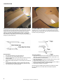
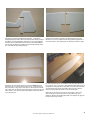
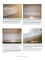
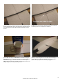
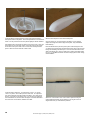
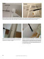
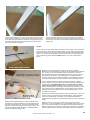
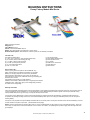
BUILDING INSTRUCTIONS
Foamy Factory Models Mini Series
Class: Indoor/Light Outdoor
Wingspan: 33"
Flying Weight: 6.5-8oz.
Servos: 3 x Pico's/hs55's/BMS 306, etc.
Battery: 2s1p 360-720mah Lipoly (depends on motor choice)
Brushless Motor Options: Little Screamers, Cemech Python 60, Axi 2208/34, Axi 2204/54
Included in Kit 3mm Depron airframe parts
(2) .121”x .034” x 36”(3mm x .8mm) flat carbon fiber strips.
(2) 8.75”x.080” (2mm) carbon landing gear legs
(2) 11”x.060” (1.5mm) carbon pushrods
(2) 4”x.060” (1.5mm) carbon pushrods
(2) ¼” x 18” balsa triangle stock
(6) .039” x 2” music wire
(1) 1/8” lite-ply firewall
(3) 3mm Depron firewall spacers
(4) 2/56 cap head screws
(2) 1.5” wheels
(4) DuBro micro control horns
(4) Dubro EZ Links
(3) Decal sheets
Not Included in Kit Servos: (3) 6-9 gram servos (HS-55, HS-50, BMS 306, etc.)
Motor: CD Rom Motor, Axi 2208/34, Axi 2204/54, or equivalent
Battery: 2-3 cell lipoy (depends on motor choice) 340-830ma
Speed controller: Appropriate for motor choice (CC Phoenix 10)
Prop: depends on motor choice, GWS 8x4.3SF is a good starting point.
Receiver: Micro receiver
Glue: Medium foam friendly Ca or UHU Creative
SHARP X-Acto knife (#11 blade works best) or single edge razor blades
Cellophane Tape: Clear glossy type (not the disappearing dull finish)
36” metal ruler or straight edge
Warranty Information
Foamy Factory Models guarantees this kit to be free from defects in both material and workmanship at the date of purchase. This warranty does not
cover any damage by use or modification. In no case shall Foamy Factory Models’ liability exceed the original cost of the purchased kit. Foamy
Factory Models reserves the right to change or modify this warranty without notice.
In that Foamy Factory Models has no control over the final assembly or material used for the final assembly, no liability shall be assumed nor
accepted for any damage resulting from the use of the final assembled product. By the act of using the assembled product, the user accepts all
resulting liability.
If the buyer is not prepared to accept the liability associated with the use of this product, the buyer is advised to return this kit immediately in new and
unused condition to the place of purchase. (See Guarantee on last page)
NOTE: All Foamy Factory kits are precision CNC router cut. Some cut flashing/fuzz may be present on some of the foam/wood parts. This is due
to the rotary cut action of the router and the direction of the cut and is not a defect. If any flashing/fuzz is present, lightly sand the edges with 1200
grit sandpaper.
All Contents Copyright © Foamy Factory Models, 2005
1
CONSTRUCTION
Take all of the foam pieces and set them aside except for the horizontal
fuselage/stabilizer piece and the elevator. Use a straight edge and a very
sharp single edge razor blade and bevel the trailing edge of the horizontal
stabilizer at about a 60 degree angle (see drawing below for beveling
method). Use regular clear cellophane tape for hinging. Use the clear
high gloss tape, not the dull finish “disappearing” tape. See diagram
below for specific hinging technique. You can use your favorite method for
hinging if you prefer another way.
**ALTERNATE METHOD** – If you would like to add a bit of strength to
the horizontal stabilizer, you can bevel the leading edge of the elevator,
and add a scrap .121”x .034” (3mm x .8mm) flat carbon fiber strip to the
trailing edge of the horizontal stab. This mod. adds tremendous strength to
the stab. with very little weight gain.
Beveling Method 1. This method will result in a nice clean, straight cut.
2. For best results, use 2 metal straight edge rulers.
3. Tape one straight-edge to your work surface with about 1/8” hanging
off edge of table.
4. Line up control surface to be cut along the edge of the ruler.
5. Place another straight-edge about ¼” from the edge of the surface to
be cut.
6. Hold the straight edge steady and draw a single edge razor along
the straight edges. Be careful to not let anything shift while cutting.
7. You now have a nice, clean beveled edge.
Tape Hinging Method 1. Apply a piece of tape to the entire leading edge of the control surface.
Apply only one half of the width of the tape to the control surface. The
other half will attach to the other surface
2. Place the control surface up against the trailing edge of the wing, at full
down control deflection.
3. Smooth down the tape making sure you get a good seal.
4. Fold the control surface forward as shown, and apply a piece of tape to
the exposed surface as shown. Smooth down tape.
5. Check hinge for freedom of movement.
Once the hinging is complete, add the decals to the elevator and rudder.
It’s much easier to do it now rather than wait until after the plane is
assembled.
2
All Contents Copyright © Foamy Factory Models, 2005
Set aside the horizontal fuselage/elevator assembly. Locate the top
fuselage half and the rudder. Bevel the rudder as shown above and hinge
the rudder to the vertical stabilizer. Make sure you leave a gap between
the bottom of the rudder balance tab and the top of the vertical stabilizer.
You can apply the decals to the rudder and top fuselage assembly at this
time. Set aside the top fuselage assembly.
Remember, the wing half with the servo cutout is the RIGHT wing half.
First thing to do is cut off the ailerons from the wing. Cut off the ailerons
along line drawn on wing using a sharp Xacto or razor blade and a metal
ruler. Make sure you mark the left and right ailerons somehow so they will
match up later. Then, glue both wing halves together using foam safe Ca
or your favorite glue.
Locate the left and right wing panels. The RIGHT wing panel has the
aileron servo cut-out in it. Make sure both wing panels fit together with a
nice clean butt joint. Sand edges lightly as necessary to achieve no gaps.
Lay both wing halves flat on your workbench with the trailing edge facing
you. Take one .121”x .034” (3mm x .8mm) flat carbon fiber strips and lay it
up against the trailing edge of the wing. Mark and cut the carbon fiber strip
so it extends the entire length of the trailing edge of the wing. Glue the
strip to the trailing edge with medium Ca or your favorite glue.
Make sure you don’t induce any warps as you are gluing. Use a long
piece of wax paper under the wing so as not to glue the wing to the
workbench. Because of the trailing edge taper, it is helpful to only glue one
half of the carbon strip at a time.
All Contents Copyright © Foamy Factory Models, 2005
3
When the glue has completely dried on the trailing edge carbon strip, glue
a .121”x .034” (3mm x .8mm) flat carbon fiber strip to the leading edge of
the wing. The carbon strip does not wrap around the curved wing tips. The
carbon strip begins where the curved tip ends and transitions to the
straight leading edge (see photo above). Again, it is helpful to only glue
one half of the strip at a time. (The carbon strip extends from tip to tip on
wings with non-curved tips.) Save the scrap carbon strips.
While you are waiting for the wing carbon strips to dry, bevel the ailerons.
Make sure you match the left and right ailerons to their appropriate sides
of the wing. Take the right aileron and flip it over (noting which edge is the
leading edge). Bevel the bottom of the leading edge at about a 60 degree
angle. Now, do the left aileron as described above. Be VERY careful
during this step. Pay attention to the left and right sides and the top and
bottom of the ailerons. There is nothing as frustrating as beveling both
ailerons identically, only to realize you now have 2 right or left ailerons.
Once the carbon is dry on the wing, and the ailerons are beveled, use tape
to hinge the ailerons. Use regular clear cellophane tape for hinging. Use
the clear high gloss tape, not the dull finish “disappearing” tape.
Fit the bottom fuselage half onto the horizontal fuselage piece making sure
to line up all of the slots and tabs. If there are any alignment issues, now is
the time to correct them. I use the nose as a reference point. Make sure all
of the slots and tabs fit and line up well. If any adjustment is needed, use
a sharp Exacto knife to trim the tabs.
Once the ailerons are hinged, you can apply the decals to the wing. It is a
bit easier to apply all of the decals before you begin final assembly.
Place the horizontal fuselage upside down on your workbench. (NOTE:
The servo cut-out will be on the LEFT side of the fuselage when upsidedown on workbench.) Draw a centerline between the forward fuselage slot
and the second fuselage slot. This line will be the wing centerline
alignment reference.
4
Once the alignment is satisfactory, insert the bottom fuselage half into the
horizontal piece. Make 2 marks with a pen where the wing cutout meets
the horizontal piece. These 2 marks will be your wing alignment marks.
All Contents Copyright © Foamy Factory Models, 2005
Next, line up the wing centerline with centerline of the horizontal fuselage,
and the alignment marks made in the previous step. Lightly trace around
the LE and TE of the wing. Be VERY careful that everything is lined up
and true.
Be VERY careful during this step! Make sure wing is lined up square to
the fuselage piece and no misalignment is introduced.
Once you are happy with the alignment, and the guidelines are correct,
glue the TOP of the wing to the BOTTOM of the horizontal fuselage piece
with the TOP of the wing facing the workbench. (You will be looking at the
BOTTOM of the wing). I used foam safe medium Ca for this step. Be
VERY careful when gluing the wing. Make sure everything is lined up and
straight. Weight down the wing while the glue dries.
Trial fit the bottom fuselage piece onto the horizontal fuselage/wing
assembly. Trim the wing cutouts on the bottom horizontal fuselage piece if
needed. Make sure all of the slots and tabs line up and everything is
square. Make any adjustments now before gluing together.
All Contents Copyright © Foamy Factory Models, 2005
5
Next, glue the bottom fuselage piece to the bottom of the horizontal
fuselage. You will have to leave the front third of the fuselage hanging off
the edge of your workbench. Make sure that everything is squared up
while the glue is drying. Block the fuselage square while glue is drying.
Locate the 1/8” light ply motor mount. Test fit the mount on the airframe
(do not glue at this time). If any adjustments are needed, carefully trim to
fit. The motor mount needs to be at a 0,0 incidence. That is no up or
down thrust and no left or right thrust.
Once the bottom fuselage is dry, test fit the top fuselage to the airframe.
Make sure everything lines up well (trim the elevator cutout if necessary
for free movement). Once you are happy with the alignment, glue the top
fuselage piece to the airframe assembly. At this point DON'T glue on the
1/4" tri stock. Save that for later.
Use the pre-drilled holes to draw 2 guidelines in an “X” connecting the
holes. Line up your motor mount using the guidelines; mark the center of
the motor mount holes, then, drill mounting holes with a 1/16” drill bit. If
you are using an Axi 2208 series motor and the Axi firewall mount, drill a
3/16” hole in the center of the firewall to allow drive shaft clearance.
Use the supplied 2/56 cap head screws to temporarily mount the motor to
the firewall. Once motor is mounted satisfactorily, remove the motor from
the firewall. You can then apply a tiny drop of thin Ca to the holes, let the
glue dry, and then re-thread the screws into the holes. This step adds a
bit of “strip resistance” to the mounting holes.
6
If you are using the Axi 2204 series (or similar) motors, the firewall must
be moved forward a bit so the prop will clear the front of the airframe.
Depron firewall spacers are included to accommodate this. BEFORE
gluing firewall to the airframe, slip 2-3 depron spacers onto the nose of the
airframe, (the firewall spacer slots may need to be trimmed slightly for a
good fit). Temporarily mount the motor to the firewall, then slide the firewall
onto the airframe and check prop clearance from the nose. You should
have at least 1/8” clearance between the prop and the nose of the
airframe. Once you determine how many spacers are needed, glue the
spacers to the rear of the firewall. Be careful to keep everything square
while gluing.
All Contents Copyright © Foamy Factory Models, 2005
Glue the motor mount to the airframe using 5 min. epoxy or medium foam
safe CA. If you use epoxy, make sure you use only a tiny bit. Epoxy is
heavy, and you don’t want to add any unnecessary weight. As the glue is
drying, check to make sure motor mount is square to the airframe and no
warps or incidence changes are introduced.
Once the motor mount is dry, glue on the nose doublers as shown. Glue
the larger one on first, then butt up the smaller one to the first one and
glue it on. These doublers add a lot of "bounce resistance" to the nose
area.
Locate the 2 strips of ¼” x ¼” balsa triangle stock. Make a mark on the
top of the horizontal fuselage 1 ½” forward of the aileron hinge line.
Measure the distance between the mark and the aft end of the horizontal
stabilizer. Cut both pieces of tri-stock to match the measured distance.
Glue the tri-stock to the fuselage joint along the top of the horizontal
fuselage and the vertical fuselage. Make sure to take care during this step
to keep everything square and not induce any warps or twists.
All Contents Copyright © Foamy Factory Models, 2005
7
Locate the 2 pieces of 2mm carbon rod and 2 pieces of 2” .039 wire.
These will be the landing gear struts and wheel axles. Bend the 2 pieces
of .039 wire at about a 45 degree angle. Tack-glue the axles to the struts
with thin Ca.
Then, wrap the wire and strut with the thread provided. Once the axle is
wrapped, soak the thread with thin Ca. (Make 2)
Locate the small piece of silicone fuel tubing. Slip the tubing onto one of
the gear legs. Now, slip the other gear leg through the tubing (make sure
you have the wheel axles on opposite sides from one another).
Slip the gear legs and tubing into the hole in the fuselage. DO NOT glue
tubing to fuselage at this time.
8
All Contents Copyright © Foamy Factory Models, 2005
On the Mini 3DX, make a small hole in the leading edge of the wing
(approx. 2 3/8" from wing centerline) Make the hole right at the carbon
leading edge wing spar. We want the gear loads to tie into the spar. For
all other airplanes, make the hole right where the fuselage meets the wing.
Now, bend the top of one of the gear legs down and push it through the
hole. The end of the carbon rod should stick out of the top of the wing
about 1/8”. Adjust the gear leg as necessary, making sure the wheel
axle is perpendicular with the fuselage. Tack glue with a small drop of
glue to the joint between the wing and the gear leg.
Turn over the airframe and place it on a flat surface so that it rests on the
gear. Check to make sure that the landing gear is adjusted so that the
airframe is level. Adjust gear legs as necessary so the wings are level
with one another, and the axle wires are perpendicular to the fuselage.
Once you are satisfied with the gear leg alignment, apply a small fillet of
glue at the gear leg/wing joint on the top of the wing and also to the
underside. You can use a tiny bit of 5 min. epoxy for this step to add more
strength to this joint.
Bend the axle wire so that it’s parallel to your work surface.
All Contents Copyright © Foamy Factory Models, 2005
9
Locate the Depron wheel pant pieces. Each wheel pant consists of 2
outer pieces, and 2 inner pieces. The 2 inner pieces have a cut-out for the
wheel. You may need to trim the inner pieces slightly for wheel clearance.
Glue together the 2 pieces with the wheel cut-out in the center. Now, glue
those pieces to one of the outer pieces. Place the wheel on the pant as
shown and center up the wheel. Punch a hole in the wheel pant with a
piece of .039” wire for the axle hole. Make 2 sets.
Locate the carbon pushrods. You will need (2) 1.5mm x 11” and (2)
1.5mm x 4” pieces. Also locate 8 pieces of .039” wire. On 4 pieces of
wire, bend a small “Z” bend with needle nose pliers. On 4 other pieces,
bend ¼” of the wire at a 90 degree angle. The “Z” bend end will be the
servo attachment end, and the other “90 degree” end will be attached to
the control horn on the ailerons, elevator and rudder.
10
Glue the last outer piece to each of the wheel pants.
Once the glue is dry, round the edges of the pant to a nice, pleasing
shape. Don't forget to round the edges of the pants. They look MUCH
better that way...
Place the wheel into the pant and push a piece of wire through the hole
you made in the previous step and through the wheel. Now, push the wire
through the remaining side of the pant. You now have axle holes on both
sides of the wheel pant. Do this to both pants. Set the wheel pants aside
for now. You will attach them later to avoid “bumping them around” during
radio installation.
Attach the “Z” bend wire to each of the 4 carbon pushrods using the
method outlined previously for the gear legs. Do not glue on the 90
degree bend wires yet. Set aside the pushrods.
All Contents Copyright © Foamy Factory Models, 2005
Radio Setup and Installation – Hook up 3 servos to the receiver you will
be using. Using the radio setup for your particular radio brand, center the
servos making sure the trims are neutral. Attach the longest servo arms
you have for your particular brand of servo. You want the most travel you
can get at the servo end of the setup. The aileron servo will use a double
ended servo arm, and the rudder and elevator servos will use a single
ended arm.
Insert one of the servos into the forward servo cutout in the fuselage.
Noting that the servo arm needs to point away from the horizontal fuselage
section. You can secure the servo with a bit of hot glue, or just a few
drops of medium foam safe Ca glue. Depending on the length of the
servo wires, you may want to orient the servo so that the wire exits the
servo case facing the front of the airplane. Do the same thing for the other
servo, however, make sure the servo faces the opposite direction so you
have control arms on either side of the fuselage.
Insert the aileron servo into the cutout on the right side of the fuselage.
You may need to trim the servo arm cutout in the vertical fuselage section
to allow full servo throw. It is easier to install the servo without the servo
arm attached. Secure the servo using the method outlined previously.
Attach one of the 4” carbon pushrods to each side of the aileron servo
control arm.
All Contents Copyright © Foamy Factory Models, 2005
11
With the servo centered, make a mark on the aileron that extends straight
out from the control rod. Do the same for the other side. Cut a 1/4” slot in
the aileron right on the mark on both ailerons. The slot should begin about
1/8” aft of the aileron hinge line. This step assures that the aileron control
horns will be lined up with the pushrods.
Locate the 4 control horns. Cut off the barb on all 4 of the horns. 2 of the
horns are for the ailerons, and one each for the rudder and elevator. The
horns will be installed by pushing them up through the slot cut in the
control surface, so these barbs are not needed. By doing this, the moment
arm of the horn is shortened, allowing more throw at the control surface for
3D flight.
Push the control horns up through the slots cut in the ailerons. (Note,
above pic. is shown on a scrap piece of depron for clarity). Securely glue
the horns into the slots. Apply a small fillet of glue around the area of the
horn where it exits the foam for extra security.
Insert one of the 90 degree bend pieces of wire through one of the holes in
the control horn. (Note, using the closest hole on the servo arm to the
control surface will allow the most control surface throw).
Make sure the aileron servo is centered, and assure the aileron is
centered also. Hold the assembly together carefully, and tack glue the
wire to the control rod with a small drop of thin Ca glue.
Remove the control rod from the horn and the aileron servo. Wrap the joint
with thread and soak the thread with thin Ca glue. Repeat for the other
aileron.
12
All Contents Copyright © Foamy Factory Models, 2005
Reattach the aileron control rods to the servo arm and the control horn and
secure the 90 degree bend with end with the EZ links provided. (Needle
nose pliers help with the EZ link installation).
**Alternate Method – You may choose to install micro EZ connectors (not
included) at the aileron, elevator and rudder servo arms. This method
allows easy adjustment of the control surfaces. If you choose to use this
method, leave the “Z” bend off of the wire at the servo horn end of the
pushrod.
Rudder/Elevator Control Rod Setup –
The rudder and elevator control rod setup is exactly the same as outlined above for the ailerons. However, use the 11” pieces of 1.5mm carbon rods.
Follow the above setup steps for the rudder and elevator. (Note, it does not matter which side the elevator and rudder control rods are set up on as long
as the AFT servo is used for rudder, and FORWARD servo is for Elevator).
All Contents Copyright © Foamy Factory Models, 2005
13
Elevator and rudder horns are attached the same way the aileron servos are. Cut a ¼” slot in the control surface as shown, push the control horn
through the slot, and securely glue in place. Make sure that when cutting the slot for the rudder horn, you allow enough room for the elevator to move
freely (locate slot about 5/8” from the bottom of the rudder). The rudder control rod should not interfere with the movement of the elevator.
Insert one of the wheel pants onto the axle as shown. Slip the wheel into
the pant and push the axle through the wheel hub. Push the axle through
the outer hole on the wheel pant. Repeat for the other side. Now, turn
the plane over so it is resting on the wheels.
14
Tack-glue the wheel pants to the carbon gear leg. When doing this, the aft
lower edge of the pant should be parallel with your work surface for proper
orientation. Once satisfactory alignment is achieved, make a glue fillet at
the gear leg as shown. Also, add a small drop of glue on the outer side of
the wheel pant where the wire axle exits the pant. (Note, this joint doesn’t
need to be “bullet proof”. It is designed to have a little bit of “give” in case
of an unexpected rough landing) If the wheel pants get knocked off, it’s
just a matter of re-gluing the joint.
All Contents Copyright © Foamy Factory Models, 2005
Locate 2 depron gear leg covers. Use a piece of tape “wrap” around the
gear leg and secure the foam. Attach a piece of tape to the front of the
cover, leaving half of the width free. Place the cover against the gear leg,
then wrap the remaining tape around the leg and secure to the cover.
Trim to fit as required for a good fit.
Tack-glue the bottom end of the cover to the wheel pant. Hard landings
may knock the wheel pant off. If that happens, just tack-glue it back on.
You can use a bit of silicone glue to attach the pants, but the silicone takes
a while to dry.
Tail Skid Locate a piece of the scrap carbon strip from the wing. Cut a slot about 1” long at the tail as
shown in the picture. Glue in the carbon strip as shown. Cut the carbon strip so that when
the airplane is resting on the gear, the tail skid is just long enough to keep the rudder off the
ground. You can leave off the landing gear and the tail skid if you plan on flying mostly off
grass. The landing gear and tail skid are VERY helpful if you fly from a hard surface or
indoors
Make sure you mount your speed controller as far forward as possible.
Depending on servo lead length, your receiver may need to be attached aft of the
CG. An easy way to mount the speed controller and receiver is to stick a 2”
piece of masking tape to the back of the ESC and receiver, then use a bit of hot
glue to attach to the airframe. For aesthetic reasons, the ESC and receiver
should be mounted under the horizontal fuselage. For lateral balance, it helps to
mount the speed controller on one side, and the receiver on the opposite side.
Once you have determined the location of the radio components, a balance
check is required. Place your fingers under the wing at the recommended center
of gravity (CG). Initial CG should be at 3 to 3 1/4” aft of where the leading
edge of the wing meets the fuselage. Determine weather the plane is nose
heavy (nose pointing down), or tail heavy (nose pointing up). Most likely, you will
end up tail heavy with no battery attached. Place the battery on the horizontal
fuselage near the CG and slide it forward or aft till the plane balances. This is
your battery cutout location.
Cut a slot in the fuselage just tall enough to slide in the battery pack. You can cut
the slot on the top or the bottom of the horizontal fuselage. Putting the battery
under the wing looks better, but putting it on top creates a better balanced
airplane (However, the battery may interfere with the aileron control rods if placed
on top).
BATTERY PLACEMENT AND INSTALLATION –
Battery placement depends largely on radio component choice.
Heavier servos require the battery to be mounted further forward
than when using lighter servos. The Foamy Factory Mini series
airplanes do not have the battery slot pre cut for this reason. The
best way to determine battery location is to completely build the
airplane and install the radio gear first.
Make sure when you cut the slot, you allow a bit of room for fore and aft
adjustment. As you fly the airplane more, you will probably want to move the CG
aft. You can do this by making the cutout longer toward the tail and sliding the
battery aft. We don’t use any Velcro or strap to secure the battery. We just use a
piece of cellophane tape on both sides of the battery to secure it to the airframe.
All Contents Copyright © Foamy Factory Models, 2005
15
SET UP AND FLYING By carefully choosing lightweight equipment, you can end up with a very light and extremely aerobatic airplane. Every extra gram makes a difference on
these small planes. A good target weight is 6.5 to 7oz. Choosing proper equipment will give you an absolutely fabulous flying airplane! Heavy servos,
receiver, etc. will take a toll on performance.
When installing the radio, make sure all of the surfaces move freely with no binding. Double check the servo and control surface attachments for
security.
Initial center of gravity (CG) should be at 3” to 3 ¼” aft of where the wing leading edge meets the fuselage. As you become more comfortable
with the airplane, you can move the CG back to suit your own preference. Flat plate wings have a fairly large CG range tolerance. An aft CG will be
easier to hover, will snap faster, and loop tighter. However, the airplane will be more pitch sensitive and may “hunt” a bit in pitch. You can help alleviate
For 3D flying, aileron throw should be 45-60 degrees, elevator throw should be 45-60 degrees, and rudder throw about 45 degrees. You can tone down
the center by using the exponential function on your radio if it is capable of it (consult your radio user manual for specific set up procedures). 30 percent
Expo is a good starting point and adjust to your own preference.
If you are new to 3D, or want to tone down the throws for a more docile flyer, set all the control surface throws at about 30 degrees. You can also use
dual rates if your radio is so equipped.
THANK YOU!
Thank you for choosing a Foamy Factory Models airplane! We know you have many choices, and it is very important to us that we deliver a quality
product that meets or exceeds your expectations. We are constantly trying to improve our models, and if you have any comments or suggestions that
you think would make this kit better, please feel free to email us at [email protected]
We have big plans for future models, so visit www.foamyfactory.com often for updates and new offerings. Also, most of the newest Foamy Factory
news, information and product support is constantly being discussed on R/C Groups. Just log onto www.ezonemag.com, then click on “Discussion”,
then click on the the “3D Flying” forum link. For a quick answer to any question you may have, Ezone is often the fastest way to get an answer. There
are always many friendly people “hanging out” and questions are often answered in just a few minutes. Of course, feel free to email us with any
questions too.
FOAMY FACTORY GUARENTEE
We strive to produce the best product that we possibly can. However, we are human, and occasionally something slips by. If for any reason you are
unsatisfied with any Foamy Factory model, we will replace it, or provide you with an immediate refund of your purchase price (not including shipping). If
you would like to receive a refund or replacement, please email [email protected] prior to returning the item. First of all, we’d like to know
what the problem is and how we can correct it, and second, you need to be provided a return authorization. For a replacement or refund, the kit must be
shipped back in its original packaging and construction on the model may not have been started. (Shipping costs incurred for the return of merchandise
is the responsibility of the sender). For replacement of damaged or defective parts, email us, and we’ll send you a replacement part right away. (No
need to send in the whole kit).
16
All Contents Copyright © Foamy Factory Models, 2005