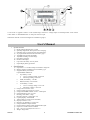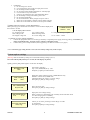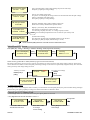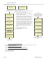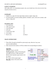
1
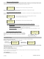
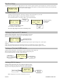
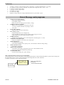
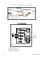
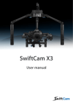
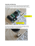
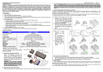
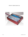
TP610C USER'S MANUAL TP610C 1 THUNDER POWER RC 1: LCD screen 2: Upgrade connector 3: BL-2 (balance tap) connector 4: Charge Output 5: Enter/Stop button 6: INC button 7: DEC button 8: SEL/MODE button 9: Data port 10: Power input Note:Please refer BL-2 connection diagram for TP batteries (page 9). User's Manual 1. System Features a) b) c) d) e) f) g) h) i) j) 2. Highly efficient Digital power system Specially designed for safe Lipo and A123 charging. Individual cell over charge protect (when balancing). 25 programmable memories for each battery type. Adjustable charge mode algorithms. Adjustable discharge cut-off voltage. Fast balance charging. Backlit LCD display. Lipo and A123 battery recovery mode Input/Output polarity protection. Specifications a) b) c) Input Power: 11-16V DC/10Amp at maximum charge rate Memory profile: 25 Memories for each battery type Supported battery chemistries: Lipo/NiMH/Nicd/PB/A123 Charge voltage and cells: battery:1-6cell Lipo CC to CV charge voltage: 4.18V/cell Full Charge Voltage 4.2V/Cell NiMh, Nicd battery: 1-14cells PB(SLA) battery: 6V/12V/24V A123 Battery: 1-6cells CC to CV change voltage: 3.6V /Cell Full charge voltage: 3.65V/Cell e) Charge Current: 0.25A---10A f) Charge control type Lipo/A123: CC/CV g) Charge Nicd/NiMH: constant current –V delta peak h) Charge/discharge cycles: 9 cycles i) Discharge rate: 50mA- 1Amp j) Discharge capacity: 7 Watt (Max 1A) k) Capacity display: 0-9999mAH l) Timeout limit: 2-10 hour (User selectable) m) Display Tolerance: 0.5% n) Display Type: Backlit 2 x 16 dot LCD o) Charge maximum output: 80 Watt p) Output Charge Terminal: 4mm standard banana jack q) Input wire: 16 AWG silicon insulated. r) Size: 118 x 85 x 28 (mm)/4.65”x3.4”x1.1” s) Weight: 265g/9.4OZ TP610C 2 THUNDER POWER RC Cautions!!! 3. a) b) c) d) e) f) g) h) i) j) k) Do not charge in a vehicle Use a high quality power supply for input power source Do not charge in direct sun light Do not charge when ambient temperature is extremely high Use and store in a dry environment Charge in an isolated area away from flammable objects Do not attempt to charge when battery pack is hot Do not charge unattended Do not use automotive battery chargers for power source Make sure to check battery chemistry settings before charging. Make sure to check that cell count is correct (Lipo/A123/PB). **Model name and software version identification. While powering up, the model name and software version should be displayed on the LCD for 2 seconds. **LCD display abbreviations: CC: Constant current CHG: Charge mode CH : Higher voltage cell CV: Constant voltage DCH: Discharge mode CL: Lower voltage cell THUNDER POWER TP610C V5.0 F-: Charge or discharge complete C1-C6: Cell#1—Cell#6 Connection to power supply and battery 1. Connect the input power leads to a 12V deep cycle battery or regulated power supply (observing polarity) Note:When you charge at maximum rating , the input current required is a minimum of 10A. Connect battery pack to output terminal (observing polarity) and balancer connector (see page 9). 2. **Note: The battery type setting must be correct (incorrect battery settings may result in a fire). System option settings (Warning:**Be sure the battery settings are correct before starting a charge cycle .**) Press and hold the [SEL] button for 2 seconds, the LCD displays as follows; Quickly press the [SEL] button again to scroll down the display. BATTERY TYPE NiCd Delta-V Setting NiCd 15mV Delta peak voltage settings for Nicd or NiMH batteries only Default is: NiCD=15mV, NiMH=5mV Adjustment allows for “hotter” or “cooler” charge. Press [INC] or [DEC] to change settings. KEY TONE OPTION KeyTone ON Key Tone ON or OFF Press [INC] or [DEC] to change settings. INPUT PWR OPTION LV C: 11.0V Input power error voltage setting. Keeps you from over discharging your car battery while at the field. Set at 11V when charging from a car battery. Press [INC] or [DEC] to change settings. LiPo/A 123 CHG Option 100% Chg TP610C Select battery chemistry Lipo , Nicd, NiMH, PB (SLA), A123 Press[INC] or [DEC] to make selection Allows you to set the percenta ge of full charge of a LiPo or A123 battery. Press [INC] or [DEC] to change settings. 3 THUNDER POWER RC LiPo /A123 Discharge cutoff voltage settings (Lipo/A123 mode only) Press[INC] or [DEC] to change settings. LiPo/A 123 Dchg Option CUT OFF: 3.45V LiPo or A123 initial charge timer: If a pack is over discharged, the charge current will be minimized until the pack voltage achieves a minimum safe starting level. Press [INC] or [DEC] to change settings. LiPo/A 123 Init Charge TimeOut: 10 MIN PB Charge TOPOFF 2.45V /CELL PB (SLA) TOPOFF voltage setting (default 2.45V/Cell) Please refer to battery manufacturers product manual. Display cycle memory data.(Nicd/NiMH mode only) This function can display the stored cycle data. “D”: Discharge capacity in mAH , “C”: Charge capacity in mAH mAHr Press and hold [ENT] button for 2sec to clear all cycle memory slots Cycle Data Cy:#1 D:00000 C:00000 System timeout setting: The maximum operating time is adjustable between 2 and 10 hours. Press [INC] or [DEC] to adjust (default setting is 5 hour). SYSTEM TIME OUT MA X TIME: xxHour **Press and hold [SEL] button for 2 seconds return to main menu screen. MainMenuLCD Screen Press [SEL] key : Charge > discharge > balancer checking mode (Lipo/A123 mode only) LiPo CHA RGE [Mxx] 5s PA CK 10.0A [SEL] LiPo Discharge 5s PA CK 10.0A [SEL] Checking Balancer >>>>> Select memory profile M1 to M10 (all battery types used in same manner) The charge mode settings can be set in any memory (25 memories) or left in previously used charge settings. Memory setting mode can be stored at M1 to M25. The most frequently used charge settings can be stored to a specifically assigned memory slot. In normal mode, previously used charge settings are used. *Memory slot select Previously used settings PRESS [ENT] LiPo/123 Charge [Sel] 3s PA CK 10.0A PRESS [INC] or [DEC]] Memory mode Normal Mode LiPo/A 123 Charge 3s PA CK 10.0A LiPo/123 Charge [M:20] 3s PA CK 10.0A To modify charge settings: The charge current can be changed to either a memory or normal mode. Press the [ENT] button, the present variable setting will begin to flash. Then, press [INC] or [DEC] to change to a desired value while it continues to flash. ChargeLipo/A123 BatteryPack To start Charge: Select cell count and current. Then press [ENT] button for 2seconds. **Very Important: Be sure the cell count is correct **. Charge start LiPo CHA RGE 3s PA CK 10.0A Press INC or DEC to select The desired cell count TP610C [ENT] LiPo Charge 3s PACK 10.0A [ENT] LiPo Charge 3s PA CK 10.0A Press [ENT] f or 2 seconds to start charge Press INC or DEC to change current setting 4 THUNDER POWER RC Cell count reconfirm message The following display is informing you that the pack is at an unsafe voltage level. Double check the pack cell count again. If the cell count is correct, press [INC] to continue charge. Cell count Error May Cause Fire XX Cell selected Charge If Correct Lipoly/A123 battery pack charge sequences( see Fig-2) Fig-2 Start charge Lipoly charging sequence is shown below. Each step is specially designed for the safe lipoy charge algorithm. 1. Checking 20.00V Pack V oltage Checking >>>>> Balancer... Balancer Connected IntBal 1M:0.010 Charge 20.000V Initial charge 05 Li 25.000V 3.0cc 00000mA h 0:00:00 Checking Pack voltage: The charger scans the pack voltage. It requires 3.2V/cell Lipo and 2.6V/cell A123 as a minimum voltage to start charge. 2. Checking balancer: The charger reads the balancer data for 30 seconds. If the balancer connector is not attached, simply press [INC] to skip the balancer checking mode. 3. If a balancer is connected to the data port, you can find the balancer model name, imbalance and pack voltage. It takes at least 10-30 seconds to get the balancer data. 4. Initial charge: If the pack voltage is too low, the charge current will be reduced until the pack voltage reaches a safe voltage. Wait for the initial charge to finish. If a timeout error occurs, please charge again or check the pack conditions. This timeout error is caused by an over discharged pack (see option settings for adjustment of this timer). 5. CC Charge (constant current charge): 6. CV Charge (Constant voltage charge): 7. Charge is completed. Fig-3 Balancer data display Press [SEL] for 2seconds to display the balancer data (C)CELL#.1 2 3 4 5 6 B.STATUS o o o o o o CH: 4.100V 6sPak CL: 4.110V 0.010 C1: 4.100V IntBal C2: 4.110V 0.010 C3: 4.100V IntBal C4 4.110V 0.010 Li 25.000V 3.0cv 00000mA h 0:00:00 C5: 4.100V IntBal C6: 4.110V 0.010 F- 25.000V 3.0A 00200mA h 0:20:00 Press[SEL] for 2 seconds to Exit. Charge complete Charge current adjustment during C/C charge The charge current setting can be adjusted from 0.25A to 125% of original charge setting while in CC charge. Press [INC] or [DEC] to change current. Check balancer data during CC/CV charge: Press [SEL] key for 2 seconds, the LCD should display as shown in fig-3. Press INC or DEC to scroll up and down to see each cell and imbalance voltage. Check charge options and input power voltage during charge: Quickly press [SEL] key, the LCD will display the charge options and input voltage. **CC (Constant current) charge: **CV (Constant voltage charge TP610C 5 THUNDER POWER RC Battery recovery mode for Lipo and A123 When a battery pack is extremely over discharged, the charger will refuse to initiate. At this time, you can increase the voltage to normal by using recovery mode. We strongly recommend this mode for experienced users only. When the LCD screen displays as below and the charge begins, press the [INC] key to activate a recovery charge mode. It is timed for 1 minute. Li 20.000V 0.00A Voltage Low Recover [+] Press [INC] key to recover low pack voltage. (Timed 1minute) Note 1: Carefully investigate the battery pack for physical damage and individual ce ll voltages before using this function. Note 2: Double check that the cell count is correct. How to check the balancer data while in idle mode Press the [SEL] key until the LCD screen displays as shown below. If a balancer is connected, the screen will display the battery cell and imbalance voltages. Checking >>>> Balancer Data Connect your battery’ balance connector to the charger’ balancer connector or use the included BL-2 PCB (see page 9). ENT INPUT:12.000V OUTPUT:22.000V Press the [ENT] key to retrieve the input and output voltages. Other important safety functions activated during charge for Lipo and A123 battery with balancer 1. Over charge protect: If any cell reaches 4.28V, the charging process will be interrupted with an error message. 2. Imbalance over 0.2V charge interruption: If any imbalance in the pack reaches greater than 0.2 v olt, an error message will be displayed along with an interruption of the charging process. 3. Incorrect cell count setting: If the cell count setting does not match the voltage of the connected battery, an error message occurs. The charge will be interrupted. How to know the balancer is linked with charger If the balancer successfully links to the charger , the “ ^ “ symbol will appear on the LCD screen as shown to the right. This will flash every second to update the pack voltage. This symbol will not display during “INITIAL CHARGING” mode. Li 21.000V 3.0cc 00000mA h ^ 0:00:00 “^” :Balancer Sign Nicd/NiMH Charge Press the [Sel] key for 2 seconds, then select the battery type, either Nicd or NiMH. (see OPTION settings) Memory or previously used charge mode: Press [INC] or [DEC] to select memory number while [Sel] flashes. NiCd Battery NiCd Charge[Sel] V =A uto C=5.0A NiMH Battery NiMH Charge[Sel] A =A uto C=5.0A Quickly press the [ENT] key, then the value will flash. Select a desired charge current by pressing [INC] or [DEC] from 0.25 to 10A (We recommend setting to a 1C charge current for best results).Then press the [ENT] key for 2 seconds to begin charging. To check the option settings and input voltage while charging, quickly press the [Sel] key. **Delta peak voltage setting: NiCd: 5-25mV adjustable (Default value 15mV). NiMH 3-15mV adjustable (Default value 5mV). If you have experienced an unexpected undercharge or overcharge, simply increase or decrease the -delta peak voltage. (the default settings are widely used for most of batteries) **For NiMH Battery: Do not charge higher than 1C for best results. TP-610C 6 THUNDER POWER RC PB (SLA) Charge As [Sel] flashes, press the [INC] or [DEC] buttons to select a memory position. Quickly press the [ENT] key, the memory slot position will flash. Select a desi red current and voltage by pressing the [INC] or [DEC]. Press the [ENT] key for 2 seconds to initiate charging. PB Charge [Sel] 12V Pack C= 5.0A Nicd/NiMH cycler Quickly press the [ENT] button. The charge, discharge current and number of cycles will flash. Press [INC] or [DEC] to change values while the screen flashes. Press the [ENT] button for 2 seconds to begin a cycle (charge/discharge). NiMh Cycle [CL #5] C=1.0A D=1A Number of cycles Cycle Data [CL #5] D:0000 C:0000 To check cycle data during a cycle: Press the [INC] or [DEC] button. Note: The cutoff voltage is the same as in discharge mode. Press [inc] or [dec] to check each cycle’ data. D: discharge C: charge mAh Discharge (Lipoly and A123 batteries) Quickly press the [Ent] button. The cell count and discharge current will flash. Press [INC] or [DEC] to change values while flashing. Press the [ENT] key for 2 seconds to start discharge. Lipo/A 123 Discharge 3sPACK D=1.0A Discharge Current Note 1: The discharge cutoff voltage can be adjusted through the system option settings (See “system option settings”) Note 2: We recommend Lipo and A123 discharge mode only for checking the capacity of those packs. Note3: Discharge will be refused if the pack voltage is lower than 50% of rated capacity (approx. 3.6v/cell). Discharge of Nicd and NiMH batteries Quickly press the [Ent] button. The discharge current and discharge cutoff voltage will flash. Press [INC] or [DEC] to change values while the flashing takes place. Press the [ENT] button for 2 seconds to initiate discharge. Discharge cutoff voltage Nicd Discharge 6.0V D=1.0A Discharge Current Discharge PB/SLA battery Quickly press the [Ent] button. The pack voltage and discharge current will flash. Press [INC] or [DEC] to change values while the flashing takes place. Press the [ENT] button for 2 seconds to initiate discharge. Pack V oltage PB Discharge 12V Pack D=1.0A Discharge Current Note: Voltage limit: 6V/12V/24. Current limit: 0.25A-1A TP610C 7 THUNDER POWER RC Definitions 1. 2. 3. 4. 5. 6. 7. 1C charge : Current of 1 times the rated capacity of the battery. Example: 4000mAh Pack = 4A charge 2s: 2 CELLS in series connection. Example: a 2s pack has the voltage of 2 cells (3.7 X 2 = 7.4V). CC Charge: Constant current charge. CV charge: Constant voltage charge. CH: Higher cell voltage. CL: Lower cell voltage Imbalance voltage: Maximum voltage differential between any cells within a pack. Error Message and symptoms 1. “Voltage error or Wrong Polarity” Check Output battery connection. Check Battery polarity Battery may be over discharged (check battery voltage) 2. “TIMEOUT INITIAL CHARGE” Battery is over discharged or wrong cell count. Run a recovery sequence (See Recovery charge). Check cell counts. 3. “Wrong CELL COUNT” Check the series cell count of the battery. 4. “Over Charge to 4.3V” Charge interrupted by an over charged cell. Check individual cell voltages and run a balance charge using 0.5A current setting. Monitor each cells voltage during this charge. 5. “UNDER VOLTGE” Voltage too low, the battery was o ver discharged (any cell under approx. 3.6 volts) . 6. “CHARGING INCOMPLETED” Charge not completed, check battery then charge again. 7. “Failure Input power” Low INPUT Power voltage Check INPUT POWER source capacity (10A, 12V minimum at maximum charge rating) 8. “Failure OUTPUT circuit” Check battery connections. 9. “IMBALANCE OVER 0.2V” Check battery pack voltage. The pack may have one or more unbalanced cells. Charge at 0.5 amp while simultaneously balancing. 10. “SYSTEM TIME OUT” Increase timeout setting (See “option settings”) How to check the data previous to an e rror interruption: All the data previous to an error interruption (current/voltage/capacity/timer) is kept until the [Ent] button is pressed. Press simply press the [Sel] button to retrieve. Note: A power interruption to the charger will cause a loss of this data. to check it out what the progress was before interrupt. ED: 21.000V 1.0A 01500mA h 0:00:00 EC: charge ED: discharge TP610C **Press the [Sel] button to retrieve. the last interruped data 8 THUNDER POWER RC Example: TP 4 / 5 cell lipo pack connection diagram BL-2 PCB BL-2 connector PCB Use both connectors for 6s TP pack NOTE: 2-3-4-5-6s CONNECTORS ARE FOR SOME CHINESE MADE PACKS ** TP Pack connections ** 2/3s Pack: use 2-3s connector 4/5s Pack: use 4-5s connector 6s pack: use 2-3s and 6s connectors TP610C 9 THUNDER POWER RC Thunder Power RC 4880 W University Ave. Unit B1 Las Vegas, NV 89103 USA TP610C 10 THUNDER POWER RC