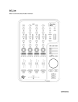
1
SCS.1m
Mixer Control Surface/Audio Interface
User Manual
Important Safety Instructions
• Read and follow the provided instructions before operating this unit.
• Adhere to all warnings and security advices, and retain this document for future reference.
Installation: Install the unit in accordance with the provided instructions
Power Supply:
• The unit should be connected to a power supply outlet only of the voltage and frequency marked on its rear panel.
• The power supply cord should be routed so that it is not likely to be walked on or pinched.
• The power supply cord of the unit should be unplugged from the wall outlet when it is to be unused for a long period of time,
or during electrical storms.
Placement and Environment:
• Locate the unit away from direct sunlight and any equipment that produces heat such as power supplies, amplifiers, and heaters.
• Place your mixer on stable surfaces, away from vibration and from sources that generate hum or noise, such as transformers,
or electric motors.
• The location and position of the unit should not interfere with its proper ventilation.
• Do not use this unit near water. For example, near a bathtub, washbowl, kitchen sink, laundry tub, in a wet basement, or near a
swimming pool.
• To reduce the risk of fire or electric shock do not expose the equipment to rain or moisture or use it in damp or wet conditions.
• Protect the unit from excessive dirt and dust.
• Avoid drinks spillage, tobacco ash, and smoke (especially that associated with smoke machines).
• Do not place heavy objects on the unit surface.
Cleaning: Unplug the unit from the wall outlet before cleaning. Never use benzine, thinner, or other solvents for cleaning. Use only a
soft damp cloth.
Service:
• The unit contains no user-serviceable parts.
• The manufacturer is not responsible for any damage or personal injury resulting from unauthorized user servicing or modifications.
Please read the warranty.
• The warranty will be void if any unauthorized service by the user is detected.
• If service is required, please contact Stanton Tech at +1 954.316.1500 (Option 3)
WARNINg
To reduce the risk of electric shock, do not expose this apparatus to rain or moisture. Ensure that the apparatus is not exposed to splashing and that no objects
filled with liquids, such as vases, are placed on the apparatus.
CAUTION
DO NOT OPEN
RISK OF ELECTRIC SHOCK
CAUTION: To reduce the risk of electric shock, do not remove any cover.
No user serviceable parts inside. Refer servicing to qualified personnel only.
The lighting flash with arrowhead symbol within the equilateral triangle is intended to alert the user to the presence of un-insulated
“dangerous voltage” within the product enclosure that may be significant enough to constitute a risk of electric shock.
The exclamation point within the equilateral triangle is intended to alert the user to the presence of important operation and maintance
(servicing) instructions in the literature accompanying this appliance.
CAUTION
To prevent electric shock, do not use this polarized plug with an extension cord, receptacle or other outlet unless the blades can be fully inserted to prevent blade
exposure.
ii
Contents
Contents
1. Introduction ……………………………………………………………………………………………………………………………………................. 1
1.1 Welcome to the SCS.1m ………………………………………………………………….…......…................................................. 1
1.2 Overview ……………………………………………………………………………………………………………………………….……............... 2
1.3 Unpacking …………………………………………………………………………………………………………………................................. 2
2. Connecting the SCS.1m ……………………………………………………………………………………………………………………................ 3
2.1 Connecting to Your Computer ……………………………………………………………………………………………….……........…….. 3
2.2 Connecting to Audio Components ……………………………………………………………………………………………........…….... 4
2.3 Connecting to the SCS.1d …………………………………………………………………………………………………………........…….... 5
2.4 SCS.1m Setups ……………………………………………………………………………………………………………………………............... 5
3 SCS.1m Description …………………………………………………………………………………………………………………….…..........…….. 6
3.1 Top Panel Functional Groups ………………………………………………………………………………....................................... 6
3.1.1 Channel Strip …………………………………………………………………………………………………….……………….........…... 8
3.1.2 Encoder Section ………………………………………………………………………………………………………...……........……... 8
3.1.3 Crossfader Section ……………………………………………………………………………………………………………........……... 9
3.1.4 Master Section ……………………………………………………………………………………………..….…........…................... 9
3.1.5 Browser Section …………………………………………………………………………………………………………..…................ 10
3.2 Front Panel …………………………………………………………………………………………………………………............................. 11
3.3 Rear Panel ……………………………………………………………………………………………………………......……......................... 12
4 SCS.1m Software Installation …………………………………………………………………………………………………………............... 13
4.1 Windows XP ……………………………………………………………………………………………………………………………................. 14
4.2 Mac OS X …………………………………………………………………………………………………………………………….….................. 22
5 DaRouter ………………………………………………………………………………………………………………………………………..............… 27
5.1 About DaRouter ………………………………………………………………………………………………………………….………..........… 27
5.2 Anatomy of DaRouter ……………………………………………………………………………………………………….…………............ 27
5.2.1 Section A ………………………………………………………………………………………………………………….…………........... 28
5.2.2 Section B ……………………………………………………………………………………………………………….………..........……. 28
5.2.3 Section C …………………………………………………………………………………………………………………….……..........…. 30
5.3 Using DaRouter …………………………………………………………………………………………………………………..…….….........… 31
5.4 Loading a Preset ………………………………………………………………………………………………………………….………............ 31
5.5 Using a Preset for the First Time ………………………………………………………………………………………………….........….. 31
6 Troubleshooting ………………………………………………………………………………………………………………….………...............… 32
7 Specifications ……………………………………………………………………………………………………………………..………..............….. 33
Appendix
Optimizing Computers for 1394 (FireWire) ………………………………………………………………………………….………..........…..
- DPC (Windows XP-Vista) ..................................................................................................................................
- Windows 1394a Bandwidth Limiting Issue (Windows XP-Vista) ......................................................................
- FireWire Chipsets .............................................................................................................................................
iii
34
34
39
49
Introduction
1.
Introduction
1.1
Welcome to the SCS.1m!
Thank you for purchasing SCS.1m! The SCS.1m (Stanton Control System 1 mixer) is the premier mixer control surface/audio
interface for laptop DJs, remixers, VJs, and producers.
Before we begin, there are a few important issues we would like to bring to your attention.
There is a software component to this hardware. It is called DaRouter. DaRouter is a kind of “MIDI processor” that allows
the use of presets. These presets can be application specific mappings, or generic maps that can be applied to a number of
different software packages. In fact, you may already be familiar with the DaRouter software because it is also used with
our SCS.3 line of controllers. Well, DaRouter is even more important for the SCS.1 controllers than it is for the
SCS.3 controllers. This is because the DaRouter software for the SCS.1 controllers also contains the driver for them. So it is
important for you to go to http://www.enterthesystem.com/scs1 to download and install the latest DaRouter software.
This single software package gives you the latest presets and the latest version of your driver. Be sure to keep your DaRouter
software updated so you can take advantage of new presets and features as they become available!
This brings us to the next important issue. Please do not connect the SCS.1 hardware to your computer before you go
through the driver install. Most audio interface installers, FireWire or USB, carry the same warning. We know that when
you buy new gear, most people are excited to hook it all up and see what it can do, but in this case, it is better to wait until
you are prompted. The process will go like this…
• You should connect the power to your SCS.1m and locate the FireWire connector, but do not connect it to the
computer yet.
• Download and run the DaRouter installer for the SCS.1m. This installer is located at
www.enterthesystem.com/scs1
• A dialog box will open telling you to connect and power up your SCS.1m. At this point, connect the FireWire cable
to your computer, then turn the unit ON.
The driver will then detect the SCS.1 devices connected to your computer and load the drivers for them. Allow the installer
to continue normally. Following these steps is a good idea for any hardware installation you have, and might save you from
possibly having to troubleshoot a problem later.
Finally, we would like to point out that the descriptions of specific functionality of the SCS.1m are generic.
The SCS.1m is a MIDI controller combined with an audio interface. Although it looks like an audio mixer, it in fact is not.
The functionality of a given control on the surface of the SCS.1m (like the crossfader for example) is dependent on what it
is assigned to. Likewise, the audio inputs and outputs may change depending on how you’re using the SCS.1m
(the Booth output could be the booth output in one program, and a recording output in another). We had to start
somewhere, so we thought it would be best to describe the functionality of the generic preset. When you are using other
presets, you can click on the Preset Documentation button in DaRouter (it’s the “?” button) to learn all about how that
specific preset works with your new SCS.1m.
1
Overview
1.2
Overview
Designed in an intuitive DJ mixer, the SCS.1m features four channel strips with faders, assignable encoder section,
EQ controls, high-precision metering, a responsive crossfader, a straightforward Cue/Monitoring section, a unique footswitch
input, and much more…
The SCS.1m and the SCS.1d (deck) are the main components of the SC System 1; the first truly professional DJ control
system. You can use the SCS.1m as standalone or in conjunction with the SCS.1d, not only to expand your configuration
options but also to control your DJ application’s main parameters. Let’s take a look of the main SCS.1m features:
•
•
•
•
•
•
•
•
•
•
Familiar 4-channel design with intuitive high-precision metering
Assignable Encoder section with 360° of LED feedback
LCD “scribble strips” for two-way communication with selected DJ software
Easy controller mapping into popular DJ and VJ software (e.g., Traktor DJ Studio™, Traktor Scratch™, Ableton Live™,
or any other MIDI compatible software)
Navigation section for remote browsing through playlists
Mic and Phono/Line input for sampling, archiving vinyl, and remixing
Built-in FireWire connections with full Mac and Windows compatibility
Perfect as a standalone mix controller, or in combination with SCS.1d
Balanced, studio-quality TRS output for mains; RCA booth output, and 1/4˝ headphones output
Unique footswitch input enabling hands-free control of software parameter
Before you start hooking up your new unit, let’s check what is in the box!
1.3
Unpacking
Please check that you have received the following items:
•
•
•
•
•
•
(1) SCS.1m unit
(1) FireWire cable
(1) 4 to 6 pin FireWire adapter
(1) Power cable and adapter (12V)
(1) Headphone extension cable
(1) SCS.1m User Manual
In addition to the above items, remember that to take advantage of the SCS.1m full potential you will need the SCS.1d or
a traditional turntable, a Mac or PC computer, a DJ application, and to install DaRouter software. So let’s get started!
2
Connecting the SCS.1m
2.
Connecting the SCS.1m
2.1
Connecting to Your Computer
Step 1:
Locate the included power cable and adapter (12V) and connect it to the SCS.1m and
to your power source. (Figure 2.1)
Note If you own both the SCS.1m and the SCS.1d, the power adapters look very similar.
Looking at the output voltage will tell you which is for which component, (e.g., 12V for
the SCS.1m, and 24V for the SCS.1d). There is also a label on each of the power cords
to specify which product they are to be used with.
Figure 2.1
Step 2:
Attach the included FireWire cable to the SCS.1m. The FireWire ports are clearly labeled
on the back panel of the SCS.1m. (Figure 2.2)
Figure 2.2
Step 3:
Download and run the DaRouter installer for the SCS.1m.
A dialog box will open telling you to connect and power up your SCS.1m. At this point,
connect the FireWire cable to your computer’s FireWire port (Figure 2.3), and then turn
the SCS.1m ON. Do not connect the SCS.1m until prompted.
Figure 2.3
On laptops, there are two different types of FireWire ports: 6 and 4 pin. Typically, you will find “full sized” 6 pin ports on
Apple laptops. If your computer has a full sized (6 pin) FireWire port, use the included FireWire cable to connect directly
from the SCS.1m to your computer.
Most PCs will have a 4 pin FireWire port. So if you have a 4 pin port on your computer, connect the FireWire cable to the
provided 4 to 6 pin adapter, and then just plug it to your computer’s 4 pin FireWire port. Now that power and FireWire are
connected, we can hook up audio in and out.
3
Connecting to Audio Components
2.2
Connecting to Audio Components
Figure 2.4
4
Connecting to the SCS.1d
2.3
Connecting to the SCS.1d
All of the SCS.1 controllers have two FireWire ports on them, so devices can be chained together if needed.
So when connecting a single SCS.1d to the SCS.1m, you would go from the unused FireWire port on the SCS.1m
(Figure 2.5), (the other port is connected to your computer) to an open port on the SCS.1d. (Figure 2.6)
Figure 2.6
Figure 2.5
Likewise, if you’re connecting two SCS.1ds to a SCS.1m, then you would go from the free FireWire port on the first SCS.1d
to a port on the second. Any other FireWire devices should go at the end of the chain and not before any of the SCS.1
controllers. Let’s take a look of the SCS.1m Setups.
2.4
SCS.1m Setups
SCS.1m
This mixer-only setup allows for basic mixing and transport control of software decks. Thanks to the SCS.1m
built-in audio interface capabilities, it is perfect for DJs wanting an all-in-one solution to play from their
software into a PA system. (Figure 2.7)
Figure 2.7
SCS.1m + SCS.1d
This mixer-and-deck configuration can be used to emulate a dual-deck setup by using virtual
decks for controlling transport, loop, and effects, while using the mixer to blend and EQ songs
and sounds. This system is the perfect entry into the world of professional SC System laptop
mixing. (Figure 2.8)
Figure 2.8
SCS.1m + Traditional Turntable
The SCS.1m mixer can be incorporated into Digital Vinyl Systems (DVS) that support MIDI
control by running the time code into a sound card and using the SCS.1m’s built-in MIDI
functionality to control the user’s preferred DJ software. (Figure 2.9)
T. 9 2 U S B
Dual SCS.1d + SCS.1m
This setup recreates the “traditional” DJ system, allowing users to have two
physical decks, each representing an on-screen deck (which can easily be toggled
to four decks by using virtual decks). The mixer is used for blending, channel EQ,
etc, in a traditional manner. This setup is tailored towards professional DJs wanting
to replace their existing setup with an SC System controller-based solution.
(Figure 2.10)
5
Figure 2.9
Figure 2.10
SCS.1m Description
3.
SCS.1m Description
In this chapter, we will briefly describe the Top, Front, and Back SCS.1m panels.
It’s important to understand that the SCS.1m is a traditional DJ mixer “analogy” in a control surface. This means that while
the SCS.1m looks like a DJ mixer, at its core, it is really a control surface. As a control surface, the SCS.1m’s functionality is
completely derived from the host application (software) that it is controlling.
The SCS.1m also utilizes presets in DaRouter to define functionality, which can drastically change its functionality depending
on how the preset is configured. So as we discuss the panel and layout it is important to remember that when running a
specific preset its best to read the documentation associated with that preset as it will explain how the SCS.1m is tailored
towards the application it is being used with. So in the below explanations we describe the controls and how they
traditionally may be mapped into an application.
3.1
Top Panel Functional groups
To easily understand the main SCS.1m Top Panel, we have divided it in five functional groups:
-
Channel Strips
Encoder Section
Crossfader Section
Master Section
Browser Section
On the next page, let’s take a look of the Figure 3.1:
6
Top Panel Functional groups
Top Panel Functional groups (continuation)
Figure 3.1
Now, let’s take a closer look of each of the functional groups.
7
Channel Strip
3.1.1
Channel Strip
The button at the top of the strip might be mapped to functionalities like deck or channel
focus, a shift modifier, etc.
Five rotary encoders in the top section of the channel strip can be mapped to traditional
mixer functions like gain, EQ, and panning. (Figure 3.2)
The A and B buttons in the lower section of the strip can be used to toggle modifiers, assign
the strip to the crossfader, etc.
The CHANNEL FADER would usually be mapped to deck or channel volume.
The buttons at the bottom of the strip can be mapped to deck focus, cue, play/pause,
record, etc.
Figure 3.2
Each strip also has a LED peak meter that responds to MIDI feedback and can be used to indicate channel Pre-Fade Listen
(PFL) if your application supports it.
3.1.2
Encoder Section
This section consists of four rotary push encoders, each with an LED encoder ring to
indicate the value of the encoder, and an LCD “scribble strip” that can be used to indicate
the functionality of each encoder. (Figure 3.3)
There are also four buttons to the right of the channel strips that can be used to change
the functionality of the encoders.
Encoders can be programmed so that the entire group of four can be used to operate a
single device or channel. For instance, four different effects parameters for a single channel.
Also, they can be set so they work as part of each channel strip so each encoder might
control a single functionality on all four channel strips - like deck key, or Aux send.
Figure 3.3
8
Crossfader Section
3.1.3
Crossfader Section
The CROSSFADER is traditionally used to fade between songs playing in different channels.
(Figure 3.4)
You might also consider mapping the CROSSFADER to non-traditional functionalities, like
effects parameters, filters, or setting selections (like scrolling through effects).
Figure 3.4
3.1.4
Master Section
The Master Section controls various SCS.1m outputs. (Figure 3.5)
The ZONE knob is meant to be mapped to an Aux out, like a booth monitor or effects send.
This is a MIDI control and does not affect the Aux output on the rear panel of the mixer.
This MIDI control would need to be assigned to the volume control in the host application
for that output.
The MASTER out can be mapped to control master output.
The HEADPHONES knob should be mapped to control the output level for the attached
headphones.
CUE MIX can be mapped to control the cue/program ratio in your headphones.
Figure 3.5
There is also an L/R peak meter that responds to MIDI feedback and can be set to indicate output levels if your software
supports it.
9
Browser Section
3.1.5
Browser Section
This area of the SCS.1m would typically be mapped to browser-type functionality, whether
that is scrolling through your library in Traktor, or selecting scenes in Ableton Live.
(Figure 3.6)
The three buttons at the top of the section can be used to select and activate banks or
directory trees.
The large push encoder can be used to scroll through and select songs, scenes, or directory
trees. It would also allow the user to scrub through songs and/or cue them.
The ENTER and CANCEL buttons can be used to answer program prompts.
Figure 3.6
The SETUP, CONTROL, and BROWSE buttons at the bottom might be used to switch the overall operation of the browser
section (for instance, change it from library navigation to song scrubbing).
10
Front Panel
3.2
Front Panel
In this panel, you will be able to connect your headphones. Stanton has included a headphone extender cable as the
headphone jack is recessed into the panel to prevent accidentally damaging the headphone jack. Stanton has designed the
headphone output to be extremely powerful and loud; it is important to remember that you must control the level of this
output in your host application or assign it to the headphone knob on the front panel for volume control. ALWAYS have the
headphone output turned down in your host application before using the headphones and slowly bring the volume up to
a comfortable level. (Figure 3.7)
WARNINg: Never put your headphones on until you are 100% sure you have control over the output level. This is good
safe practice and something which should become second nature to you.
Figure 3.7
11
Rear Panel
3.3
Rear Panel
In 2.2 “Connecting to audio components,” we gave you an iconic representation of what could be connected to the SCS.1m.
Here, we will briefly describe the Rear panel. (Figure 3.8)
Figure 3.8
1. Power Switch: Turns the SCS.1m ON or OFF.
2. DC IN: Input connection for the included power supply. While the power is switched OFF, plug the power supply into
the mixer first, and then plug it into the outlet.
3. FireWire Jacks: Sends audio and MIDI to and from the SCS.1m. Multiple MIDI devices can be strung together to
create a chain of SCS components. Check Chapter 2.3.
4. Master Output: The main outputs are ¼” Balanced TRS jacks. Ideally, you will be going to a balanced input from the
main outputs. Used for sending balanced master audio bus to PA, the master outputs are extremely loud so it is
suggested to first bring the volume of the master outputs completely down in your host application before playback.
5. Zone Output: This is an unbalanced RCA and probably where you are going to hook up your booth monitor, or it can
be used as a Record Out or as an Aux Out for external FX.
6. Phono/Line Input: This is an RCA input where you would connect a CD player, a turntable, (for example to record
real-time samples or playback of non digital audio medium) or other external devices. Note that there is a LINE/PHONO
switch attached to this input that you should set according to what you have connected. When connecting a turntable,
this should be set to PHONO. If your turntable has a ground cable, attach it to the grounding post (GND) located directly
above the LINE/PHONO switch.
7. Trim: the Trim knobs and clip indicators for both inputs will let you adjust the incoming audio signal.
8. Mic Input: Connect a microphone for sampling your voice or getting the crowd hyped up!
9. Footswitch Input: A footswitch may be connected for toggling of virtual decks or any other MIDI control in software.
Important The SCS.1m is not an analog mixer, even though it looks like one. It is a MIDI Controller and an Audio Interface
(soundcard). Because of this, the operation of the inputs and outputs is largely determined by the software it is running
with. For instance, if you are using a program that will accept an audio source as an input, then you will be able to use the
input jacks. However, if your software does not support incoming audio, then you will not hear from devices connected to
the SCS.1m inputs no matter how they are connected.
Now that everything is connected and you have a better idea about the SCS.1m panels, let’s install the SCS.1m Software.
12
SCS.1m Software Installation
4.
SCS.1m Software Installation
To fully maximize SCS.1m capabilities and take advantage of its great features, some software needs to be installed with it.
In fact, the SCS.1m Software Installation process differs greatly between Mac and PC computers.
- On a Mac, the SCS.1m is Core Audio compliant, which means that the OS will recognize the SCS.1m without needing
to install a driver. However, on a Mac you will need to install DaRouter for proper MIDI functionality.
- In Windows, an ASIO driver needs to be installed. An ASIO driver allows your audio software to communicate directly
with your SCS.1m without going through the normal operating system processing, which lowers latency, and can give
you higher audio quality (Core Audio acts in the same way as an ASIO driver but without the need for extra software).
To make installation easier for Windows users, we have included the driver installation in the SCS.1 DaRouter
installation, meaning there is still only one installer to run.
In either case, (Mac or PC) the DaRouter software needs to be installed. This software acts as an intermediary between
your SCS.1 controllers and your performance software, intercepting and processing MIDI messages before sending them
out to your application of choice. This process takes less than a millisecond, and gives you some amazing power. Not only
does it allow you to quickly change the MIDI output of the SCS.1 controllers (by switching presets), it also allows for
logic-based programming that your performance software may or may not be capable of performing. This means that it is
actually possible to add or change some functionality in your software of choice. This can be as simple as adding MIDI data
to an application that does not normally support it, to totally changing the behavior of a given control.
In short, if you are a PC user, you will run one installer that will install the SCS.1m driver and DaRouter. If you are a Mac
user, you do not need to install any driver. You just need to make a few easy settings in the Audio MIDI Setup applet and
install DaRouter.
Before walking through specific installation procedures for Mac and PC, you will need to download the latest version of
DaRouter from the Stanton website:
www.enterthesystem.com/scs1
So, let’s follow the specific instructions for each platform.
13
DaRouter Installation - Windows XP
4.1
Windows XP
1. Double click the executable file (.exe). If the following Open File- Security Warning appears, click Run. (Figure 4.1)
Figure 4.1
2. The Stanton SCS.1 DaRouter Setup Wizard will guide you through the installation process. Click Next. (Figure 4.2)
Figure 4.2
14
DaRouter Installation - Windows XP
3. To install the software for the first time, choose the Standard option. To update your previously installed version,
choose Custom. In this example, let’s choose Standard. (Figure 4.3)
Figure 4.3
4. Read the License Agreement, select the “I accept the agreement” option, and then click Next. (Figure 4.4)
Figure 4.4
15
Stanton 1394 ASIO Driver Installation - Windows XP
5. The installation of the ASIO driver will begin. Make sure that your SCS.1 controller(s) are properly connected but
do not turn them ON yet. When you are ready, click Next. (Figure 4.5)
Figure 4.5
6. Please wait while Stanton 1394 ASIO Driver is being installed, and then turn your SCS.1 controllers ON and click OK.
(Figure 4.6)
Figure 4.6
16
Stanton 1394 ASIO Driver Installation - Windows XP
7. We are almost ready to complete the Stanton 1394 ASIO Driver Setup installation. Click Next. (Figure 4.7)
Figure 4.7
8. Stanton 1394 ASIO Driver has been installed. Click Finish to close this wizard. (Figure 4.8)
Figure 4.8
17
Bome’s Virtual MIDI Ports Installation - Windows XP
9. Now let’s install Bome’s Virtual MIDI ports. Read carefully the following instructions and click OK. (Figure 4.9)
Figure 4.9
10. Select No, not this time and click Next. (Figure 4.10)
Figure 4.10
18
Bome’s Virtual MIDI Ports Installation - Windows XP
11. Select Install the software automatically and click Next. (Figure 4.11)
Figure 4.11
12. Click Continue Anyway. (Figure 4.12)
Figure 4.12
19
Bome’s Virtual MIDI Ports Installation
13. Click Finish to complete the Bome’s Virtual MIDI Port device. (Figure 4.13)
Figure 4.13
20
Installation Verification - Windows XP
To check that your drivers and software are properly installed, open Device Manager. On your desktop, right click
My Computer icon and click Properties. In the System Properties window, click the Hardware tab, and then the Device
Manager button. (Figure 4.14)
Figure 4.14
You will see a new section called Stanton 1394 Audio Devices that includes the Stanton 1394 Virtual Device and a hardware
specific driver for each controller you have connected. Check that the SCS.1m and SCS.1d devices are attached to your
computer.
You can also click the Start button and verify that all associated applications appear there. (Figure 4.15)
Figure 4.15
You will see a driver program group, along with an SCS.1 DaRouter icon. That is it. You are done!
21
DaRouter Installation - Mac OS X
4.2
Mac OS X
Before you install DaRouter, please follow these easy steps:
1. Connect SCS.1 controllers to the computer's FireWire port but have them powered OFF.
Turn ON your SCS.1m controller. Open the Audio MIDI Setup applet to make sure it is recognized.
The Audio MIDI Setup applet is located in Applications\Utilities. You should see the SCS.1m located in the Audio tab.
(Figure 4.16)
Figure 4.16
22
DaRouter Installation - Mac OS X
To install DaRouter, please follow the next instructions
1. Double click the .dmg file to expand it. (Figure 4.17)
Figure 4.17
2. Double click the DaRouter.pkg file to start the installer. (Figure 4.18)
Figure 4.18
23
DaRouter Installation - Mac OS X
3. Once the installer has started, click Continue. (Figure 4.19)
Figure 4.19
4. Read the license agreement and click Continue. In the next dialog, click Agree. (Figure 4.20)
Figure 4.20
24
DaRouter Installation - Mac OS X
5. Next, you can set the default path of the program. Click Install unless you want to install DaRouter to a specific
destination. (Figure 4.21)
Figure 4.21
6. DaRouter will be installed. Once done, click Close. (Figure 4.22)
Figure 4.22
25
DaRouter Installation - Mac OS X
7. DaRouter will be installed into your Applications folder and the presets will be placed in your home directory.
Plug in your SCS.1m, start DaRouter, and read the rest of this documentation. (Figure 4.23)
Figure 4.23
Now that you have installed DaRouter, let’s learn about it.
26
DaRouter
5.
DaRouter
5.1
About DaRouter
DaRouter is an application developed between Stanton and Bome’s Software, which allows SCS.1m to specifically integrate
and interact with audio applications. DaRouter takes incoming messages coming from SCS.1m using a proprietary high
speed messaging protocol and translates them to the host target audio application through the form of presets.
This translation process allows the unit to change its functionality depending on which mode the unit is in and the desired
host application functionality. Every single action on SCS.1m is processed through DaRouter, which means that as
applications evolve, so do presets… More importantly, presets can be created and edited freely with virtually no limit to
what SCS.1m can do, thus opening up a whole element in control surface DJing. It is important to constantly check the
Stanton website and forums for new presets.
5.2
Anatomy of DaRouter
DaRouter is the brains behind interaction between SCS.1m and the application it is being used with. DaRouter is designed
to sit in the background and just translate MIDI but does have some functionality to load presets and configure your SCS.1m
with DaRouter/Active preset. Before we load a preset, let’s take a quick tour of what everything inside of DaRouter does.
To easily describe DaRouter, we divided its interface in three sections: A, B, and C respectively. (Figure 5.1)
Figure 5.1
27
DaRouter - Section A
5.2.1
Section A
Active Preset Dropdown
The Active Preset is the currently used preset. In this drop down menu,
all pre-installed presets will be listed as well as any presets dragged or
manually loaded into DaRouter. To load a preset into DaRouter, just
select one from the list.
At the bottom of the drop down list is a Browse listing that can be used
to manually browse a preset using a file explorer dialog.
Restart Preset Button
The Restart button will start the currently running preset. This should
not need to be used, but gives you the option to restart a preset in case
of any problems.
Figure 5.2
Preset Documentation Button
The Preset Documentation button (shown as “?”) will load the HTML documentation associated with the selected preset.
The preset documentation includes all the setup instructions for using the preset with the application it was designed for.
To fully take advantage of the SCS.1m capabilities it is strongly recommended to click the Preset Documentation button and
read its content every time that you load a new preset. (Figure 5.2)
5.2.2
Section B
Device Configuration
This section indicates if a device is required for use with a preset, and if
that device is connected. For “Single” presets, only one device is
required. For “Dual” presets, two devices are required. When a device
is not used in a preset, the image will be ghosted. When a device is used,
the image will be gray, and when the device is detected (plugged in), it
will glow blue to indicate connectivity.
Device Dropdown
The device dropdown menu will list any detected devices by their serial
number. Selecting a device will assign it to the deck used in the preset.
Once this assignment is made, DaRouter will remember the assignment
for future use so you do not need to assign the device each time.
(Figure 5.3)
Figure 5.3
28
DaRouter - SCS.1m Options
Options
Below each Device Dropdown menu there is a button called Options. Clicking on it will allow you to change several
important settings.
For example, if you click the SCS.1m Options button the
SCS.1m Audio Control Panel will open so you will be able to Start and Stop
the streaming process, access the Deferred Procedure Calls (DPC) Latency
Checker (for more information please read the Appendix), and select the
Sampling Rate, FireWire Latency, and ASIO Buffering settings. (Figure 5.4)
Start / Stop Streaming – Use this to start or stop the audio stream
between the driver and hardware. If streaming has been stopped then no
audio will be passed to the hardware.
DPC Latency Tool – Stanton includes a troubleshooting tool for detecting
high DPC latency. When there is high DPC latency apparent on a machine
it can affect the performance of audio and MIDI streaming. You must have
low DPC latency to achieve consistent performance and low latencies.
Sampling Rate – Sampling rate will set the resolution of the audio coming
from the outputs of SCS.1m. Higher sampling rates mean more audio
fidelity but also more processing on the computer and should only be
used on newer machines. Another consideration is the material being
played. For instance, 96 kHz should only be used if your source audio is
high resolution whereas 44.1 kHz or 48 kHz should be used for MP3’s and
CD quality content.
FireWire Latency – This sets the latency or speed in which audio is sent
to the hardware. Low latency will make the controls feel “snappier.”
However, your computer must be able to support these low speeds. If the
computer cannot support low latency, then audio hiccups or “drop outs”
might be observed. If low latency is not achieved with a high-end
machine, it is suggested to use the DPC tool and follow the instructions
in Appendix for system optimization.
Figure 5.4
ASIO Buffering – This controls the buffers used between the driver and
host application. Low buffering will mean higher speed / lower latency
but requires a high-end computer.
29
DaRouter - SCS.1d Options
Now, if you click the SCS.1d Options button the SCS.1d Control Panel will
open, so you will be able to change the Scratch Engage, the Scratch
Release, and Pitch Bend Sensitivity values. (Figure 5.5)
Scratch Engage Sensitivity – The SCS.1d uses an algorithm to detect
scratching to accommodate MIDI scratching implementation in host
applications such as Traktor. The Scratch Engage slider will set how quickly
the scratch algorithm will detect that you are trying to perform a scratch.
Higher settings will make the algorithm more snappy. However, if you set
this value too high you run the risk of mistriggering a scratch message
with the slightest variance in record speed.
Scratch Release Sensitivity – This slider controls how quickly the SCS.1d
will detect the record being released and catching up to speed with the
platter thus entering regular playback mode and disabling scratching in
the host application.
Pitch Bend Sensitivity – The SCS.1d also has the ability to detect when
the platter is being rubbed manually by hand to slow or speed the track
up. This is detected when the platter and record change speed at the same
time (whereas with scratching the platter keeps spinning at its set speed).
Setting this value will change the sensitivity and once again, making it too
sensitive might cause mistriggers of the pitch bend message going to the
host application.
Figure 5.5
5.2.3
Section C
Activity Monitor
The activity monitor indicates messages flowing in and out of DaRouter.
The first arrow indicates an incoming message. The DaRouter icon
indicates a translation occurring, and the last arrow indicates an
outgoing message. The images will glow blue to indicate they are
processing an action.
Logos
Just for bling... actually, they do link to websites.
Version
This displays the current version of DaRouter. (Figure 5.6)
Figure 5.6
30
Using DaRouter
5.3
Using DaRouter
When using DaRouter, there are two basic types of presets that you may utilize; generic and application specific.
The generic preset allows you to configure the application to SCS.1m through conventional MIDI Learn. However, the
application specific presets are designed to work specifically with certain applications and provide logic in SCS.1m that is
focused towards that application.
5.4
Loading a Preset
Confirm that no preset is loaded and your SCS.1m is connected. At this point, you may select the preset you wish to use
and then read its included documentation by clicking the “?” button. Also, remember to check the Stanton website for the
latest presets as they are constantly being updated to support new functionality and applications!
5.5
Using a Preset for the First Time
1)Select the desired preset you would like to use depending on which application you are using DaRouter with.
2)Move any SCS.1m faders or knobs, to confirm feedback is making its way into DaRouter and the unit should load
the preset and stop flashing.
3)Now you are ready to use the preset.
Important Click the “?” button next to the preset (Figure 5.7) to read its included HTML documentation which explains
setting up the host application and the functionality of the SCS.1m with that particular preset.
Figure 5.7
For more information about SCS.1m, please visit http://www.enterthesystem.com/system/scs1m_mixer/ and check its
related links.
31
Troubleshooting
6.
Troubleshooting
1. I have both the SCS.1m and SCS.1d, and when I try to power them up nothing happens. What is wrong?
You probably have the power supplies for each controller swapped. If you plug the wrong power cord into a unit,
it won’t power up. The power cable for the SCS.1m supplies 12V, and the one for the SCS.1d supplies 24V. You can
also tell which is which by the color-coding. For example, gray for the SCS.1m and blue for the SCS.1d.
2. Can I use the FireWire cable alone to power the SCS.1 controllers?
No, the SCS.1 controllers require external power. We intentionally wanted power to be supplied to guarantee
that consistent performance is achievable as not all bus power on the FireWire port is stable across machines.
3. I cannot find the driver for my controller.
In Windows, the driver installer is combined into the SCS.1 DaRouter software. In OS X, the SCS.1m is
Core Audio compliant and doesn’t need a driver. As stated in the installation procedure, make sure you download the
latest driver from the Stanton website.
4. My computer does not have a 6 pin FireWire port on it.
Use the 6 to 4 pin adapter included in the SCS.1m package.
5. My computer doesn’t have a FireWire adapter at all.
In most cases, a FireWire interface can be easily added to a computer. For laptops, you need to look for either a
PCMCIA or ExpressCard based adapter (which one to use depends on the card slot your computer is equipped with).
For desktops, you should use an add-in PCI FireWire card. Please do not use a USB-to-FireWire adapter cable because
it will severely degrade performance.
6. I am getting click and pops in my audio.
This can be many things. Do you hear noise even when there’s no software playback? If so, then the cause is likely a
ground loop (especially if it goes away when running the computer on battery power). If not, does increasing the
buffering in the driver make the problem go away? If so, then it could be an issue with your system performance.
For OS tweaks, please read the Appendix DPC Optimization Guide. If neither of the previous options seems to fix the
issue, let’s try a couple of more alternatives.
Do you have multiple FireWire devices connected? If so, try using just the SCS.1m. If that addresses your issue,
then try re-ordering the devices in the FireWire chain. You should always have the SCS.1 controllers “closest” to the
computer and plug other devices (drives, etc) into them (or run your drives on a separate port altogether). If you’re
running Windows XP, you might need the SidSpeed fix. Please see these Microsoft articles to determine if this is a fix
for your issue…
For XP SP2, go to http://support.microsoft.com/kb/885222
For XP SP3, go to http://support.microsoft.com/kb/955408/en-us
To contact Tech Support, please call us at +1 954.316.1500 and select the SCS.1 option.
32
Specifications
7.
Specifications
Output Level Balanced
+23 dBu into 100K
Equalization (20 Hz-20 kHz)
Less than +/- 0.4 dB
Balanced THD+N (1 kHz)
Less than 0.005%
Balanced Output SNR (A-weighted)
Greater than 108 dB
Balanced Output crosstalk
Less than -100 dB
RCA Output level
+17 dBu into 100K
RCA THD+N (1 kHz)
Less than 0.003 %
RCA SNR (A-weighted)
Greater than 108 dB
RCA crosstalk
Less than -100 dB
+13 dBu into 600R
+13 dBu into 150R
Less than 0.009% into 600R
Less than 0.04% into 150R
Headphone Output
Headphone THD+N
Headphone SNR (A-weighted)
Greater than 95.5 dB
Headphone crosstalk
Less than -80 dB into 600R
Input full-scale (Mic)
+12 dBu (min gain)
+40 dBu (max gain)
Input SNR (Mic) (600R) (A-weighted)
Input THD+N (Mic)
Greater than 100 dB at min gain.
Greater than 83 dB at max gain.
Less than 0.004% @ -12.5 dB min gain.
Less than 0.015% @ -41 dB max gain.
Input full-scale (RCA Line)
2.45 dBu (Max Gain)
Input SNR (RCA Line)
Greater than 102 dB
Input THD+N (RCA Line)
Less than 0.005%
Line crosstalk
Less than -60 dB
Input full-scale (RCA Phono)
-33.8 dBu @ 1 kHz
Input SNR (RCA Phono)
Greater than 85.3 dB (system I)
Greater than 90 dB (33R gnd plug)
Input THD+N (RCA Phono)
Less than 0.009% @ -35 dBu input
Phono crosstalk
Less than -86 dB
33
Appendix - Optimizing Computers for 1394
Appendix
Optimizing Computers for 1394 (FireWire)
When using any computer for live audio applications it is always suggested to perform certain optimizations to ensure
consistent performance. For the most part live audio is not always the highest consideration for both hardware designers
and software programmers. With that being said, Stanton has put together this guide and included one of the most widely
used troubleshooting tools (DPC Latency Checker) with the SCS1 to help optimize your computer by performing certain
tweaks, which we have found increases performance and stability substantially.
If you are having issues getting your computer to recognize the SCS.1m then it is suggested to start with the SidSpeed fix.
If you are having issues with audio performance (drop outs) then it is first suggested to perform the following steps:
•
•
•
•
•
•
Disable wireless internet devices
If running Windows on a Mac (Boot Camp), kill the process “KbdMgr.exe”
Disable ACPI
Perform DPC checks (below)
Perform the SidSpeed fix (below)
Check the brand of 1394 host controller you are using.
Please read the next page about the (DPC) Latency Checker.
DPC (Windows XP-Vista)
During the SCS.1m driver installation process, we are also installing the Deferred Procedure Calls (DPC) Latency Checker.
This useful Windows application not only analyzes how your computer is handling real-time data streams but also helps
you to find the potential cause for drop-outs (interruptions in real-time audio and video stream). In fact, the DPC Latency
Checker will allow you to find out the driver that causes the excessive DPC latencies so then you are able to disable it
through the Windows Device Manager. In other words, using this application will help you to optimize your system so
everything runs smoothly while using the SCS.1m.
Let’s take a look of its main window. (Figure A.1)
34
Appendix - DPC (Windows XP-Vista)
Figure A.1
The green Bar Graph shows the current latency value over time. Each bar represents the maximum DPC latency occurred
within one second. Every second, bars are scrolled from right to left and a new bar is added at the right-hand side,
(representing the most recent value).
DPC Latency Checker updates its internal statistical data at an interval displayed as Test Interval.
The Current Latency value indicates the maximum DPC latency measured within the last second.
The Absolute Maximum value represents the maximum latency measured since the tool was started.
Click Reset to clear this value.
To stop the Latency click Stop, and to exit the application click Exit.
35
Appendix - DPC (Windows XP-Vista)
For example, a typical problem is shown in the next figure. Red bars indicate excessive DPC latency. (Figure A.2)
Figure A.2
So let’s open Device Manager to find out the driver that causes the excessive DPC latencies. On your desktop, right click
My Computer icon and click Properties. In the System Properties window, click the Hardware tab, and then click the
Device Manager button. In the next page, please check Figure A.3.
36
Appendix - DPC (Windows XP-Vista)
Figure A.3
Now, before you start finding out which device could be the cause of the excessive DPC latency, please follow these
suggestions:
You should not disable:
•
•
•
•
•
•
•
any device listed in Device Manager under System devices or Computer
the hard disk that contains the system partition
the IDE/ATAPI or SATA controller this hard disk is connected to
the system keyboard
the mouse, track point or touch pad device
the USB controller external keyboard and/or mouse devices are connected to
the display controller listed under Display adapters
Try to disable the following devices first:
•
•
•
•
•
Network adapters for Ethernet and Wireless LAN (W-LAN)
ACPI Power Management
Internal modems
Internal sound devices (on-board sound systems)
Any PCI or PCI Express add-on card, any PCCard or ExpressCard, e.g., TV tuner cards, ISDN or DSL adapters,
modems, etc.
37
Appendix - DPC (Windows XP-Vista)
To disable a device, right-click on it (e.g. on the Ethernet adapter) and choose Disable. The disabled device will be marked
with a red cross. (Figure A.4)
Figure A.4
Now, check the DPC Latency Checker to see if the excessive latency values (red bars) disappeared.
If yes, we have found the problem, if not, try the next device. To enable a device again, choose Enable from the context
menu.
After you have identified the device driver which is responsible for the dropouts, visit the device vendor's Web site or
contact its Customer Support department to find an update for this driver. If there is no update available at the moment,
you may decide to disable that particular device while you are using streaming applications.
38
Appendix - Windows 1394a Bandwidth Limiting Issue (Windows XP-Vista)
Windows 1394a Bandwidth Limiting Issue (Windows XP-Vista)
First, let’s explain a little about what the SidSpeed Fix is. Basically, SidSpeed is a value in your windows registry that regulates
the speed of your FireWire bus. It can have a value from 0-3 (0=S100 speed, 1=S200 speed, 2=S400 speed, and 3=800
speed). If a SidSpeed value larger than 3 is used, then Windows will reject that and use a value of 0 instead, so it’s important
to use a value of 0-3.
Normally, the default value for SidSpeed is 2, which corresponds to a transfer rate of 400 mbps (FireWire 400).
This speed is standard for most audio interfaces, including ours. The problem is that there are situations where this value
can be lowered to “0” during an OS update and result in choppy and unusable performance for streaming audio. This issue
seems to have first been encountered in the SP2 update for Windows XP…
http://support.microsoft.com/kb/885222
…and came back again with the XP SP3 update.
http://support.microsoft.com/kb/955408/en-us
We’ve also seen incorrect (or no) SidSpeed value set in Windows Vista. So now that you have some background, let’s walk
through a fix that should work regardless of what version of Windows you’re using.
Log in as Administrator on your computer (or as a User that has Administrator rights). Click on Start, and then click Run.
(Figure A.5)
Figure A.5
This will open the Run command box. In the entry field, type the word regedit and click OK (Figure A.6)
Figure A.6
39
Appendix - Windows 1394a Bandwidth Limiting Issue (Windows XP-Vista)
This will open your Registry Editor, which will look like this…(Figure A.7)
Figure A.7
Now, before we go any further, we need to give you a warning and back some things up.
The registry is a dangerous place to be playing around. Using this tool makes it very easy to completely ruin your installation
of Windows. Please do not do anything that isn’t outlined in this guide. If you have any question at all about what you
should be doing, stop and contact Technical Support.
OK, now we’re ready to backup your registry (or at least the part of it that we’ll be modifying). Look in the left hand side of
the split pane in regedit and locate the branch called HKEY_LOCAL_MACHINE. Click it once to highlight it. (Figure A.8)
Figure A.8
40
Appendix - Windows 1394a Bandwidth Limiting Issue (Windows XP-Vista)
Now click File, and then click Export. A new window will pop up. (Figure A.9)
Figure A.9
At the bottom of the new window, there is an area called Export Range. Make sure that Selected Branch is marked, and
that the text in the field there says HKEY_LOCAL_MACHINE. Go to the top of the window and find the Save In drop down.
Select a location to save the backup that you will remember (like your desktop). Now go down to the File Name field and
type in a name for the backup. Press the Save button and wait until the hourglass disappears. You have now backed up a
registry branch. Although this is not necessary, at this point I would recommend also saving the registry backup you just
made to an external device like a USB flash drive. If you make a mistake and there are problems booting into Windows
later, this will make restoring the registry much easier. Now let’s look for the SidSpeed value.
Expand HKEY_LOCAL_MACHINE (Figure A.10)
Figure A.10
41
Appendix - Windows 1394a Bandwidth Limiting Issue (Windows XP-Vista)
Then expand the SYSTEM branch. (Figure A.11)
Figure A.11
Then expand CurrentControlSet. (Figure A.12)
Figure A.12
42
Appendix - Windows 1394a Bandwidth Limiting Issue (Windows XP-Vista)
Now expand Enum. (Figure A.13)
Figure A.13
43
Appendix - Windows 1394a Bandwidth Limiting Issue (Windows XP-Vista)
Then expand the PCI branch. (Figure A.14)
Figure A.14
Now we need to find the specific key for your FireWire controller. As you can see, all the devices are named in a way that
does not seem to make a whole lot of sense. It is not as hard as it may look.
44
Appendix - Windows 1394a Bandwidth Limiting Issue (Windows XP-Vista)
Leave the Regedit window open and go back to Start > Run. Type in devmgmt.msc and then press OK. (Figure A.15)
Figure A.15
This will open your Device Manager. Look for your FireWire controller (commonly called IEEE 1394). One example is
highlighted in Figure A.16.
Figure A.16
Right click on your FireWire device and click Properties.
45
Appendix - Windows 1394a Bandwidth Limiting Issue (Windows XP-Vista)
Now click on the Details tab. (Figure A.17)
Figure A.17
See this string of text? This is what we are going to look for in the PCI branch we have open in Regedit.
Going back to Regedit, we can see that I got a little lucky and have it as the first key. (Figure A.18)
Figure A.18
46
Appendix - Windows 1394a Bandwidth Limiting Issue (Windows XP-Vista)
If you expand out the device subkey, you’ll find another subkey called Device Parameters. Click it to select it and look in
the right pane. (Figure A.19)
Figure A.19
In the example above, the SidSpeed key actually exists, but it is set to the incorrect speed. Double click on the SidSpeed
value and a window will open. In that window will be a field called Value Data. If that value is a 0 or 1, CHANGE IT to a 3
and press OK. If you do not see the SidSpeed value at all, keep reading. (Figure A.20)
Figure A.20
47
Appendix - Windows 1394a Bandwidth Limiting Issue (Windows XP-Vista)
If you do not have the SidSpeed value, you will need to make one. Right click in the right pane and select New > DWORD
Value. (Figure A.21)
Figure A.21
Once you have created a new string, name it SidSpeed (Figure A.22)
Figure A.22
Finally, double click SidSpeed and change its value data to 3 as outlined above. Press OK and close the Registry Editor.
If you encounter an error during any step of this process (especially Vista users and errors about not having proper rights
to alter a registry value), please contact Stanton Technical support. If you made a mistake and need to restore your registry,
just double click on the backup you made right before we started and follow the prompts. Reboot afterwards.
48
Appendix - FireWire Chipsets
FireWire Chipsets
High definition audio flowing over FireWire requires a consistent stream between the chipset in the host computer and
the chipset in the SCS1 device. Unfortunately, some FireWire chipsets have known issues when it comes to the reliability
and synchronization required for streaming audio. It is suggested to use name brand PCI and PCMCIA cards such as Adaptec®
when your PC does not have FireWire capabilities, as some no-name or “OEM” FireWire cards will use chipsets of FireWire
that have subpar performance and can affect stability or at worst the device will not work at all. Stanton recommends the
Texas Instruments® FireWire chips for streaming audio. It is also suggested to stay away from Agere® chipsets as in testing
issues have been identified with these chipsets. Most Apple computers utilize Texas Instruments chipsets. However, it was
reported that in late 2007 Apple had switched to Agere chipsets for some production runs.
The easiest way to check if you have a Texas Instruments chipset is to run Device Manager and check the name of your
host controller. (Figure A.23)
Figure A.23
49
Registration Card
Thank you for choosing Stanton!
Your satisfaction is extremely important to us. We proudly stand behind the quality of our work and appreciate that you
put your trust in us. Registering your product will help us guarantee that you are kept up to date on our latest advances.
Warranty Service in the United States:
Please contact Stanton Tech Support BEFORE sending your product. In some cases, our Tech Support team can resolve your
problem immediately, avoiding down time due to shipping delays. However, if Tech Support determines that a repair is
needed; please call us at +1 954.316.1500 (Option 3) to obtain a Return Authorization Number (RA#) PRIOR to shipping
your product to us.
Warranty Service outside the United States:
To initiate a warranty repair, please contact the authorized Stanton dealer from whom you purchased your product, and
follow the dealer’s return policy.
Save your shipping boxes and all packaging materials!
For the fastest and safest product return to Stanton, please use the original shipping carton and packaging materials. Stanton
cannot be responsible for any damages incurred during the shipping process due to poor or inadequate packing.
Please remember to insure your shipment!
50
Stanton Warranty
Stanton Warranty
Through Stanton's authorized dealers around the World, Stanton, or one of Stanton's authorized distributors outside the U.S., will, without charge, repair
or replace, at the sole discretion of the entity responsible for making the repair or providing the replacement, any Stanton merchandise proved defective
in material or workmanship for a period of one (1) year following the date of original purchase. Exceptions to this warranty are as noted below:
The warranty for mechanical parts which are subject to wear and tear are limited to either the earlier of thirty (30) days following the date of original
purchase or for 10,000 cycles for switches.
Stanton will warrant all replacement parts and repairs for ninety (90) days from the date of original shipment. Repairs made necessary by reason of misuse,
alteration, normal wear, or accident are not covered under this warranty.
Returns
Authorized Stanton dealers are only authorized to sell and distribute merchandise within a specific country. All goods requiring warranty repair or
replacement must be returned (freight prepaid if not hand-delivered) to the authorized Stanton dealer from whom the merchandise was purchased and in
the same country where the merchandise was purchased. For purposes of purchases made via the Internet, the merchandise must be returned to the
authorized Stanton dealer in the country where the authorized Stanton dealer which sold the merchandise to purchaser is located and not the authorized
Stanton dealer in the country where the purchaser is located or the country in which the merchandise was received. Any returns to a non-authorized dealer
or to an authorized Stanton dealer not in the same country as the merchandise was intended to be sold or as set forth above will void this warranty.
To initiate a warranty repair, you must contact the authorized Stanton dealer from whom you purchased the merchandise, and follow such authorized
Stanton dealer's return policy.
Stanton assumes no risk and shall be subject to no liability for damages or loss resulting from the specific use or application made of the merchandise.
Stanton's liability for any claim, whether based on breach of contract, negligence, infringement of any rights of any party, or product liability, and relating
to the merchandise shall not exceed the price received by Stanton from your purchase of such merchandise. In no event will Stanton be liable for any
special, incidental or consequential damages (including loss of use, loss of profit and claims of third parties) however caused, whether by the negligence of
Stanton or otherwise. To the extent permitted by law and except as otherwise provided above, Stanton disclaims any express or implied warranties of
merchantability or fitness for a particular purpose.
The above warranty provides you with specific legal rights. You may also have additional rights, which are subject to variation from state to state and country
to country.
If there is a dispute regarding the warranty of merchandise that does not fall under the warranty conditions stated above, please include a written explanation
with the merchandise when returned pursuant to the terms and conditions set forth herein.
51
Notes
..................................................................................................................................................................................................
..................................................................................................................................................................................................
..................................................................................................................................................................................................
..................................................................................................................................................................................................
..................................................................................................................................................................................................
..................................................................................................................................................................................................
..................................................................................................................................................................................................
..................................................................................................................................................................................................
..................................................................................................................................................................................................
..................................................................................................................................................................................................
..................................................................................................................................................................................................
..................................................................................................................................................................................................
..................................................................................................................................................................................................
..................................................................................................................................................................................................
..................................................................................................................................................................................................
..................................................................................................................................................................................................
..................................................................................................................................................................................................
..................................................................................................................................................................................................
..................................................................................................................................................................................................
..................................................................................................................................................................................................
..................................................................................................................................................................................................
..................................................................................................................................................................................................
..................................................................................................................................................................................................
..................................................................................................................................................................................................
52
Copyright © 2008 Stanton Magnetics, Inc.
SC System, DaRouter, SCS.1m, and SCS.1d are trademarks of the Stanton Group.
All other trademarks are property of their respective owners, who are in no way affiliated with Stanton DJ or SC System products.
All information included in the User Manual is subject to change without notice.
(+1.877.578. 6866)
LITS00033 4/01/2009