1
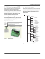
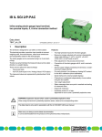
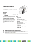
IL ETH BK DI8 DO4 2TX-XC-PAC
Modbus/TCP(UDP) bus coupler,
version for extreme conditions,
8 inputs, 24 V DC, 4 outputs, 24 V DC, 500 mA
Data sheet
8501_en_01
1
© PHOENIX CONTACT 2012-09-09
Description
The bus coupler is the link between an Ethernet network and
the Inline installation system.
–
Up to 61 Inline devices can be connected at any point to an
existing Ethernet network using the bus coupler. The bus
coupler and the Inline devices form one station with a
maximum of 63 local bus devices. Here, the inputs and
outputs of the bus coupler together form the first and second
local bus devices.
–
–
Up to 16 PCP devices can be operated on the bus coupler.
Thanks to special engineering measures and tests, the
terminal can be used under extreme ambient conditions.
Features
–
–
–
–
2 x Ethernet twisted pair according to 802.3 with auto
negation and auto crossover connected via an
integrated 3-port switch (2 external ports, 1 internal
port)
Transmission speeds of 10 Mbps and 100 Mbps
Ethernet connection via 8-pos. RJ45 female connector
Electrical isolation of Ethernet interface and logic
–
–
–
–
–
–
–
–
Software interface: Modbus/TCP, Modbus/UDP, or DDI
(Device Driver Interface)
Process data access via XML
Ethernet TCP/IP
– Management via SNMP
– Integrated web server
IP address setting via BootP (can be switched off)
Automatic baud rate detection on the local bus
(500 kbps or 2 Mbps)
Status and diagnostic LEDs
Eight digital inputs
Four digital outputs
Can be used under extreme ambient conditions
Painted PCBs
Extended temperature range T2 (-40°C … +55°C)
This data sheet is only valid in association with the IL SYS INST UM E user manual.
Make sure you always use the latest documentation.
It can be downloaded at www.phoenixcontact.net/catalog.
IL ETH BK DI8 DO4 2TX-XC-PAC
Table of contents
1
Description.................................................................................................................................. 1
2
Ordering data.............................................................................................................................. 3
3
Technical data ............................................................................................................................ 4
4
Tested successfully: Use under extreme ambient conditions ..................................................... 7
5
Basic circuit diagram................................................................................................................... 8
6
Local diagnostic and status indicators ........................................................................................ 9
7
Reset button ..............................................................................................................................10
8
Connecting Ethernet, supply, actuators, and sensors................................................................10
9
Startup .......................................................................................................................................12
10 Web-based management (WBM) ..............................................................................................13
11 Startup behavior of the bus coupler ...........................................................................................18
12 Monitoring functions ..................................................................................................................20
13 Modbus protocol........................................................................................................................23
14 Modbus/TCP PCP registers.......................................................................................................30
15 Device Driver Interface (DDI) .....................................................................................................31
16 Firmware services......................................................................................................................32
17 PCP communication ..................................................................................................................33
18 Simple Network Management Protocol (SNMP) ........................................................................34
8501_en_01
PHOENIX CONTACT
2
IL ETH BK DI8 DO4 2TX-XC-PAC
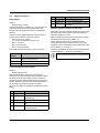
2
Ordering data
Product
Description
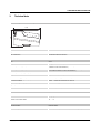
Modbus/TCP(UDP) bus coupler, version for extreme conditions, 8 inputs,
24 V DC, 4 outputs, 24 V DC, 500 mA, complete with I/O connectors
Accessories
Type
Order No.
Pcs. / Pkt.
IL ETH BK DI8 DO4 2TX-XC-PAC
2701388
1
Order No.
Pcs. / Pkt.
Snap-on end bracket, for 35 mm NS 35/7.5 or NS 35/15 DIN rail, can be fit- CLIPFIX 35
ted with Zack strip ZB 8 and ZB 8/27, terminal strip marker KLM 2 and KLM,
width: 9.5 mm, color: gray (Assembly)
3022218
50
Insert strip, Sheet, white, Unlabeled, Can be labeled with: Office-Drucksys- ESL 62X46
teme, Plotter: Laser printer, Mounting type: Insert, Lettering field: 62 x 46
mm (Marking)
0809502
5
Labeling field, width: 48.8 mm (Marking)
Type
IB IL FIELD 8
Insert strip, Sheet, white, Unlabeled, Can be labeled with: Office-Drucksys- ESL 62X10
teme, Plotter: Laser printer, Mounting type: Insert, Lettering field: 62 x 10
mm (Marking)
2727515
10
0809492
1
Labeling field, width: 12.2 mm (Marking)
IB IL FIELD 2
2727501
10
CD-ROM, with user documentation in PDF format, driver software and
sample programs, IO configurator (Literature)
CD FL IL 24 BK
2832069
1
RJ45 connector, shielded, with bend protection sleeve, 2 pieces, gray for
straight cables, for assembly on site. For connections that are not crossed,
it is recommended that you use the connector set with gray bend protection
sleeve. (Plug/Adapter)
FL PLUG RJ45 GR/2
2744856
1
RJ45 connector, shielded, with bend protection sleeve, 2 pieces, green for
crossed cables, for assembly on site. For connections that are crossed, it
is recommended that the connector set with green bend protection sleeves
is used. (Plug/Adapter)
FL PLUG RJ45 GN/2
2744571
1
CAT5-SF/UTP cable (J-02YS(ST)C HP 2 x 2 x 24 AWG), heavy-duty ins- FL CAT5 HEAVY
tallation cable, 2 x 2 x 0.22 mm², solid conductor, shielded, outer sheath:
7.8 mm diameter, inner sheath: 5.75 mm ± 0.15 mm diameter (Cable/conductor)
2744814
1
CAT5-SF/UTP cable (J-LI02YS(ST)C H 2 x 2 x 26 AWG), light-duty, flexible installation cable 2 x 2 x 0.14 mm², stranded, shielded, outer sheath:
5.75 mm ± 0.15 mm diameter (Cable/conductor)
FL CAT5 FLEX
2744830
1
Crimping pliers, for assembling the RJ45 connectors FL PLUG RJ45..., for
assembly on site (Tools)
FL CRIMPTOOL
2744869
1
End clamp, for assembly on NS 32 or NS 35/7.5 DIN rail (Assembly)
E/UK
1201442
50
Connector set, for Inline bus coupler with I/Os mounted in rows (Plug/Adapter)
IL BKDIO-PLSET
2878599
1
Documentation
Type
Order No.
Pcs. / Pkt.
User manual, English, Automation terminals of the Inline product range
IL SYS INST UM E
-
-
Application note, German/English, I/O modules at bus couplers
AH IL BK IO LIST
-
-
User manual, English, for drivers for G4-based controller boards, only
available as a download.
IBS PC SC SWD UM E
2745172
1
User manual, English, for firmware messages of Generation 4 controller
boards, only available as a download.
IBS SYS FW G4 UM E
2745185
1
User manual, English, for the Peripherals Communication Protocol (PCP),
only available as a download.
IBS SYS PCP G4 UM E
2745169
1
8501_en_01
PHOENIX CONTACT
3
IL ETH BK DI8 DO4 2TX-XC-PAC
3
Technical data
Dimensions (nominal sizes in mm)
71,5
119,8
Width
80 mm
Height
119.8 mm
Depth
71.5 mm
Note on dimensions
Specfications with male connectors
General data
Color
green
Weight
375 g (with male connectors)
Ambient temperature (operation)
-40 °C ... 55 °C (See also the "Tested successfully: Use under extreme ambient
conditions" section of the data sheet.)
Ambient temperature (operation)
-40 °C ... 60 °C (At US < 24.5 V; see also the "Tested successfully: Use under extreme ambient conditions" section of the data sheet.)
Ambient temperature (storage/transport)
-40 °C ... 85 °C
Temperature class
T2 (-40°C ... 55°C, EN 50155)
Permissible humidity (operation)
10 % ... 95 % (according to DIN EN 61131-2)
Permissible humidity (storage/transport)
10 % ... 95 % (according to DIN EN 61131-2)
Air pressure (operation)
70 kPa ... 106 kPa (up to 3000 m above sea level)
Air pressure (storage/transport)
70 kPa ... 106 kPa (up to 3000 m above sea level)
Degree of protection
IP20
Protection class
III, IEC 61140, EN 61140, VDE 0140-1
Connection data
Name
Inline connectors
Connection method
Spring-cage connection
Conductor cross section solid / stranded
0.08 mm² ... 1.5 mm²
Conductor cross section [AWG]
28 ... 16
Interface Inline local bus
Connection method
Inline data jumper
Transmission speed
500 kBit/s, 2 MBit/s (Automatic detection, no combined system)
8501_en_01
PHOENIX CONTACT
4
IL ETH BK DI8 DO4 2TX-XC-PAC
Interface Modbus/TCP(UDP)
Number
2
Connection method
RJ45 female connector, auto negotiation
Transmission speed
10/100 MBit/s
Transmission physics
Ethernet in RJ45 twisted pair
System limits of the bus coupler
Number of supported devices
max. 63 (per station)
Number of local bus devices that can be connected
max. 61 (On board I/Os are two devices)
Number of devices with parameter channel (PCP)
max. 16
Support of branch termials with remote bus branch
No
Observe the logic current consumption of each device when configuring an Inline station. It is specified in every terminal-specific data sheet.
The current consumption can differ depending on the individual terminal. The permissible number of devices that can be connected therefore
depends on the specific station structure.
Power supply for module electronics
Connection method
Spring-cage connection
Name
Bus coupler supply UBC; Communications power UL (7.5 V) and the analog supply UANA (24 V) are generated from the bus coupler supply.
Supply voltage
24 V DC (via Inline connector)
Supply voltage range
19.2 V DC ... 30 V DC (including all tolerances, including ripple)
Supply current
70 mA
Current consumption
max. 0.98 A (from UBK)
Power loss
Typ. 3 W (Entire device)
Power consumption
NOTE: Electronics may be damaged when overloaded
Provide external fuses for the 24 V areas UBK, UM, and US. The power supply unit must be able to supply four times the nominal current of the
external fuse, to ensure that it trips in the event of an error.
Main circuit supply UM
24 V DC
Supply voltage range UM
19.2 V DC ... 30 V DC (including all tolerances, including ripple)
Power supply at UM
max. 8 A DC (Sum of UM + US)
Current consumption from UM
max. 8 A DC
Segment supply voltage US
24 V DC
Supply voltage range US
19.2 V DC ... 30 V DC (including all tolerances, including ripple)
Power supply at US
max. 8 A DC (Sum of UM + US)
Current consumption from US
max. 8 A DC
Communications power UL
7.5 V DC ±5%
Power supply at UL
max. 0.8 A DC
I/O supply voltage UANA
24 V DC
Supply voltage range UANA
19.2 V DC ... 30 V DC (including all tolerances, including ripple)
Power supply at UANA
max. 0.5 A DC
Digital inputs
Number of inputs
8
Connection method
Inline connectors
Connection method
2, 3-wire
Description of the input
EN 61131-2 type 1
8501_en_01
PHOENIX CONTACT
5
IL ETH BK DI8 DO4 2TX-XC-PAC
Digital inputs
Nominal input voltage
24 V DC
Nominal input current
Typ. 3 mA
Current flow
Limited to 3 mA, maximum
Input voltage range "0" signal
-30 V DC ... 5 V DC
Input voltage range "1" signal
15 V DC ... 30 V DC
Delay at signal change from 0 to 1
1.2 ms
Delay at signal change from 1 to 0
1.2 ms
Permissible conductor length to the sensor
100 m
Protection against polarity reversal
Suppressor diode
Digital outputs
Number of outputs
4
Connection method
Inline connectors
Connection method
2, 3-wire
Nominal output voltage
24 V DC
Maximum output current per channel
500 mA
Maximum output current per device
2A
Nominal load, ohmic
12 W
Nominal load, inductive
12 VA (1.2 H; 48 Ω)
Nominal load, lamp
12 W
Signal delay
Typ. 1.2 ms
Maximum operating frequency with inductive nominal load
0.5 Hz (1.2 H; 48 Ω)
Behavior at voltage switch-off
The output follows the power supply without delay
Limitation of the voltage induced on circuit interruption
Approx. -30 V
Output current when switched off
max. 10 µA (When not loaded, a voltage can be measured even at an output that
is not set.)
Behavior with overload
Auto restart
Behavior with inductive overload
Output can be destroyed
Reverse voltage resistance to short pulses
Reverse voltage proof
Resistance to permanent reverse voltage
max. 2 A
Overcurrent shut-down
min. 0.7 A
Short-circuit and overload protection
Free running circuit In output driver
Error messages to the higher level control or computer system
Short-circuit / overload of the digital outputs
Yes
Sensor supply failure
Yes
Failure of the actuator supply
Yes
Mechanical tests
Vibration resistance in acc. with IEC 60068-2-6
5g
Shock test in acc. with IEC 60068-2-27
Operation: 25 g, 11 ms duration, semi-sinusoidal shock impulse
Conformance with EMC Directive 2004/108/EC
Noise immunity test in accordance with EN 61000-6-2
Electrostatic discharge (ESD) EN 61000-4-2/IEC 61000-4-2
Criterion B; 6 kV contact discharge, 8 kV air discharge
Electromagnetic fields EN 61000-4-3/IEC 61000-4-3
Criterion A; Field intensity: 10 V/m
Fast transients (burst) EN 61000-4-4/IEC 61000-4-4
Criterion A; all interfaces 1 kV
Criterion B; all interfaces 2 kV
8501_en_01
PHOENIX CONTACT
6
IL ETH BK DI8 DO4 2TX-XC-PAC
Conformance with EMC Directive 2004/108/EC
Transient surge voltage (surge) EN 61000-4-5/IEC 61000-4-5
Criterion B; supply lines DC: 0.5 kV/0.5 kV (symmetrical/asymmetrical); fieldbus
cable shield 1 kV
Conducted interference EN 61000-4-6/IEC 61000-4-6
Criterion A; Test voltage 10 V
Noise emission test as per EN 61000-6-4
EN 55011
Class A
Approvals
For the latest approvals, please visit www.phoenixcontact.net/catalog.
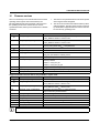
4
Tested successfully: Use under
extreme ambient conditions
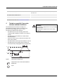
The terminal has been tested successfully over
250 temperature change cycles in accordance with
IEC 61131-2 in the range from -40°C to +70°C.
The following conditions were observed:
– The Inline devices for all connecting cables were
connected with a minimum conductor cross section of
0.5 mm²
– The Inline station was installed on a wall-mounted
horizontal DIN rail
– Fans were used to ensure continuous movement of air
in the control cabinet
– The Inline station was not exposed to vibration or shock
– The Inline station was operated with a maximum of
24.5 V (ensured by using regulated power supply units)
WARNING:
The terminal is not approved for use in potentially
explosive areas.
The terminal is not approved for use in safety
technology.
3 h + 30 min
t1
Tmax + 2 K
(3 + 0,6) K/min
Tmin + 3 K
3 h + 30 min
t1
1
Figure 1
Temperature change cycle
Temperature in the control cabinet/ambient
temperature
Cycle
8501_en_01
PHOENIX CONTACT
7
IL ETH BK DI8 DO4 2TX-XC-PAC
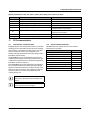
5
Basic circuit diagram
IB
µP
Local bus
B
DO1...4
DI1...8
U L+
UANA
U L-
8 x DI
7.5V
C
24V
24V
24V
4x
DO
US
UM
A
US
UBK
UM
2 TX ETH
PWR
7275A016
Figure 2
Basic circuit diagram of the Ethernet bus coupler
Key:
µ P
Microprocessor
The gray areas in the basic circuit diagram represent the electrically
isolated areas:
IB
Protocol chip
A: Ethernet interface
B: Logic
C: I/O
Optocoupler
Ethernet switch
PNP transistor
Transmitter with electrical isolation
8501_en_01
PHOENIX CONTACT
8
IL ETH BK DI8 DO4 2TX-XC-PAC
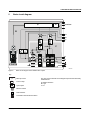
6
Local diagnostic and status
indicators
I2
PWR
I2
PWR
BO
DIA UL
US
UM
RY
PP
NF
CO PAC
BF
ETH
4 2T
DO
DI8 1
H BK 0398
IL ET-No.: 2700 .xx
/1 xx
er
Ord W: 00xx.xx.
/F
HW Addr.: ET
AC
N
M
R
ET
LNK1
BF
LED Color State
NF
Red
ON
ACT1
CO
Red
I2
X-
HE
OFF
5 6
7 8
I1
O1
PWR
RY
PP
UL
NF
US
CO
UM
BO
D
E
2
1
4
3
2
1
4
3
I1
7
5
8
6
ON
I1
DIA
ACT2
LNK2
RE
SE
LN
X1
LN
OFF
1
K1
AC
1 2
3 4
T
T
AC
O1
D E
T2
K2
1 2
3 4
X2
O1
PWR: Supply
UL
Green
ON
Figure 3
Indicators on the bus coupler
LED Color State
ETH/PWR: Ethernet
LNK Green
1/2
ON
OFF
ACT Yellow
1/2
ON
OFF
BO
Green
ON
Flashing
OFF
RY
Green
ON
Flashing
OFF
PP
Yellow
ON
OFF
8501_en_01
Meaning
Link port 1/2
Connection via Ethernet to a
module via port 1/2 has been
established.
No connection established via
port 1/2.
Port 1 activity
Sending or receiving Ethernet
telegrams at port 1/2
Not sending or receiving
Ethernet telegrams at port 1/2
Bootloader (Boot)
Boot loader active, firmware
started
Waiting for BootP reply
Firmware started successfully
Ready
Connection to a process data
client (Modbus/TCP (UDP) or
DDI) established
Firmware ready to operate
Firmware not active
Plug and play
Plug and play mode active
Plug and play mode not active
OFF
US
Green
ON
OFF
UM
Green
ON
OFF
Meaning
Network failure
A network error occurred. The
monitoring function detected an
error or the process data
watchdog was activated.
No network error, normal state
Configuration
The active station configuration
differs from the saved
configuration
The active station configuration
matches the saved
configuration.
ULogic
24 V bus coupler supply/
internal communications power
present
24 V bus coupler supply/
internal communications power
not present
USegment
24 V segment circuit supply/
internal communications power
present
24 V segment circuit supply/
internal communications power
not present
UMain
24 V main circuit supply/internal
communications power present
24 V I/O supply/internal
communications power not
present
PHOENIX CONTACT
9
IL ETH BK DI8 DO4 2TX-XC-PAC
LED Color State
Meaning
O1: Diagnostics of the Inline station/diagnostics and
status of the outputs
D
Green
Diagnostics
ON
Data transmission within the
station is active
Flashing Data transmission within the
station is not active
E
Red
Error
ON
Short circuit/overload at one of
the outputs
OFF
No short circuit/overload of
outputs
1-4 Yellow
O1 ... O4
ON
Output active
OFF
Output not active
I1: Status of the inputs
1-8 Yellow
I1 ... I8
ON
Input active
OFF
Input not active
7
Reset button
The reset button is located on the front of the bus coupler.
It has two functions:
– Restarting the bus coupler
– Restoring the default settings
To restore the default settings (see page 12), hold down the
reset button when applying the power supply.
8
Connecting Ethernet, supply,
actuators, and sensors
8.1
Connecting Ethernet
R J 4 5
Figure 5
P in 1
T D +
P in 2
T D -
P in 3
R D +
P in 4
re s .
P in 5
re s .
P in 6
R D -
P in 7
re s .
P in 8
re s .
Pin assignment of the 8-pos. RJ45
female connector
Connect Ethernet to the bus coupler via an 8-pos. RJ45
connector. For the pin assignment, please refer to the
following table:
Pin
1
2
3
4
5
6
7
8
Assignment
TxD + (transmit data +)
TxD - (transmit data -)
RxD+ (receive data +)
Reserved
Reserved
RxD - (receive data -)
Reserved
Reserved
Both Ethernet interfaces are equipped with the
auto crossover function.
IL ETH BK DI8 DO4 2TX-PAC
Order-No.: 2703981
HW/FW: 00/100
MAC Addr.: xx.xx.xx.xx
ETHERNET
RESET
PWR
O1
I1
BO RY
D E
UL PP
US NF
UM CO
1
3
2
4
I2
Shielding
1
3
2
4
5 7
6 8
The shielding ground of the connected twisted
pair cables is electrically connected with the
female connector. When connecting network
segments, avoid ground loops, potential transfers
and voltage equalization currents via the braided
shield.
RESET
LNK1
ACT1
X1
LNK2
ACT2
X2
7275A006
Figure 4
8501_en_01
Reset button
PHOENIX CONTACT
10
IL ETH BK DI8 DO4 2TX-XC-PAC
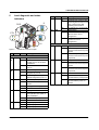
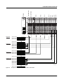
Terminal point assignment of the power connector (1)
Observe bending radii
The housing dimensions specified under
"Documentation" on page 3 refer to the bus
coupler with Inline connectors without Ethernet
connection. When installing the bus coupler in a
control box observe the bending radii of the
Ethernet cables and the connectors used (e.g.,
FL CAT5 FLEX: 30 mm for permanent installation
and FL CAT5 HEAVY: 30 mm without outer
sheath and 45 mm with outer sheath; see also
www.interbusclub.com/itc/eth/). If required, use
angled RJ45 connectors to maintain these
bending radii.
8.2
Connecting the supply, actuators, and sensors
PWR
1.1 2.1
1.1
1
1.2
2
1
1.2 2.2
2
1.3 2.3
1.3
3
3
1.4 2.4
1.4
4
4
O1
1.1
1
2.2
1.2
2
2.3
2.4
1.3
1.4
1
Figure 6
I1
1.1 2.1
2.1
1
1.1
1
2
2.2
1.2
2
1.2 2.2
1.3 2.3
2.3
3
3
1.4 2.4
2.4
4
4
1.3
1.4
1
3.1
1
2
2.2
3.2
2
1.3 2.3
3
1.4 2.4
4
4
2.3
2.4
3.3
3.4
3
2
3.1 4.1
2.1
1.2 2.2
3
1
4.1
2
4.2
3.2 4.2
3.3 4.3
4.3
3
3
3.4 4.4
4.4
4
4
4
7275B003
Terminal point assignment of the Inline
connectors
B
Assignment
Terminal
points
2.1
US
UBK
2.2
UBK GND
2.3
Functional earth 2.4
ground (FE)
Assignment
UM
UM
UM, US GND
Functional earth
ground (FE)
NOTE: Malfunction
The module is designed exclusively for operation
with safety extra-low voltage (SELV) according to
IEC 950/EN 60950/VDE 0805.
For information on the power supplies, please
refer to the IL SYS INST UM E user manual.
I2
1.1 2.1
2.1
Terminal
points
1.1
1.2
1.3
1.4
PWR DO4 DI4 DI4
2
1
3
4
Terminal points 1.3 and 2.3 on the connector can
be jumpered if the same reference potential is to
be used for the communications power and the
segment voltage.
Terminal point assignment of the output connector (2)
Terminal
points
1.1
1.2
1.3
1.4
Assignment
OUT1
GND
FE
OUT3
Terminal
points
2.1
2.2
2.3
2.4
Assignment
OUT2
GND
FE
OUT4
Terminal point assignment of the input connector (3)
US
IN6
+
-
+24 V
+
+24 V
UBK-
IN8
Terminal
points
1.1
1.2
1.3
1.4
Assignment
IN1
UM
GND
IN3
Terminal
points
2.1
2.2
2.3
2.4
Assignment
IN2
UM
GND
IN4
UM
Figure 7
OUT2
+
-
Ethernet
OUT3
Terminal point assignment of the input connector (4)
Connection example
B: Internal jumper
7275B004
Terminal
points
3.1
3.2
3.3
3.4
Assignment
IN5
UM
GND
IN7
Terminal
points
4.1
4.2
4.3
4.4
Assignment
IN6
UM
GND
IN8
Connect the bus coupler according to Figure 7.
8501_en_01
PHOENIX CONTACT
11
IL ETH BK DI8 DO4 2TX-XC-PAC
9
Startup
9.3
9.1
Delivery state/default settings
Initial startup:
By default upon delivery, the following functions and
features are available:
–
–
–
–
–
IP Configuration
IP Address:
Subnet Mask:
Default Gateway:
BootP Requests:
Software Update
Software Update on Next
Reboot:
TFTP-Server IP Address:
Downloadable File Name:
System Identification
Name of Device:
Description:
Physical Location:
Contact:
Process Data Monitoring
Process Data Watchdog
Timeout:
Fault Response Mode:
Plug and play mode
Expert mode
0.0.0.0
0.0.0.0
0.0.0.0
Enable
Disable
0.0.0.0
c2703981.fw
IL ETH BK DI8 DO4
2TX-PAC
Ethernet bus terminal
Unknown
Unknown
Sending BootP requests
During initial startup, the bus coupler transmits BootP
requests without interruption until it receives a valid IP
address. The requests are transmitted at varying intervals
(2 s, 4 s, 8 s, 2 s, 4 s, etc.) so that the network is not loaded
unnecessarily.
If valid IP parameters are received, they are saved as
configuration data by the bus coupler.
Further startups:
If the bus coupler already has valid configuration data and
BootP is not disabled, it only transmits three more BootP
requests on a restart. If it receives a BootP reply, the new
parameters are saved. If the bus coupler does not receive a
reply, it starts with the previous configuration. If BootP is
disabled and a valid configuration is available, the bus
coupler starts immediately.
For the definition of the IP address via BootP, you
can use any BootP server available.
To check whether BootP is disabled, refer to the
"IP Configuration" menu in WBM, see page 14.
500 ms
Reset Fault Mode
(Default)
Enable
Disable
By default upon delivery, the bus coupler has no
valid IP parameters.
9.2
Starting the firmware
The firmware is started after you have supplied power to the
bus coupler. The following sequence appears on the LEDs:
Display
BO flashing
BO ON
BO OFF
RY flashing
8501_en_01
Meaning
Boot loader is started,
BootP requests are being sent
Extracting firmware
Starting the firmware
Firmware ready to operate
PHOENIX CONTACT
12
IL ETH BK DI8 DO4 2TX-XC-PAC
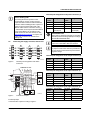
10
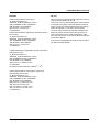
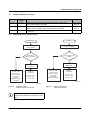
Web-based management (WBM)
The bus coupler has a web server, which generates the
required pages for web-based management and,
depending on the requirements of the user, sends them to
the "Factory Manager" or a standard web browser. Webbased management can be used to access static
information (e.g., technical data, MAC address) or dynamic
information (e.g., IP address, status information) or to
change the configuration (password-protected).
10.2
Structure of the web pages
The web pages for the Ethernet bus coupler are divided into
two sections. The left-hand side has the selection menu with
the relevant submenus. The right-hand side displays the
information related to the menu item. Static and dynamic
information about the bus coupler can be found in the
following menus.
< ip - a d d r e s s >
in d e x .h tm
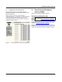
10.1
Calling web-based management
G e n e ra l
In s tr u c io n s
The IL ETH BK DI8 DO4 2TX-XC-PAC web server can be
addressed using the IP address if configured
correspondingly. The bus coupler homepage is accessed
by entering the URL "http://ip address".
In fo r m a tio n
g e n in s t.h tm
-
D e v ic e
In fo r m a tio n
G e n e ra l d e v in fo .h tm
Example: http://172.16.113.38
T e c h n ic a l D a ta te c h d a ta .h tm
H a r d w a r e In s ta lla tio n
h w in s ta l.h tm
If you cannot access the WBM pages, check the
connection settings in your browser and
deactivate the proxy, if set.
L o c a l D ia g n o s tic s
lo c d ia g .h tm
-
-
D e v ic e
C o n fig u r a tio n
IP C o n fig u r a tio n
ip c o n fig .h tm
-
ip c o n in f.h tm
S y s te m
Id e n tific a tio n
s y s c o n f.h tm
-
s y s in fo .h tm
S o ftw a re U p d a te
s w u p d a te .h tm
-
s w u p in fo .h tm
ftp in fo .h tm
C h a n g e P a s s w o rd
p a s s w o rd .h tm
-
p a s s in fo .h tm
In lin e
S ta tio n
S e r v ic e s s e r v ic e s .h tm
s v p p in fo .h tm
s v p fin fo .h tm
P r o c e s s D a ta M o n ito r in g
p d m o n it.h tm
-
p d m o n in f.h tm
p d n fin fo .h tm
Figure 8
R e m o te D ia g n o s tic s
r e m d ia g .h tm
WBM homepage
B u s C o n fig u r a tio n
b u s c o n f.h tm
P C P C o n fig u r a tio n
p c p c o n f.h tm
-
p c p in fo .h tm
Figure 9
8501_en_01
Structure of the web pages
PHOENIX CONTACT
13
IL ETH BK DI8 DO4 2TX-XC-PAC
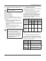
10.3
"IP Configuration" menu
Figure 9 illustrates the set IP parameters and addressing
mechanism. To change the IP parameters via WBM, "BootP
Requests" must be set to "Disable" or BootP requests to the
bus coupler must not be answered (no BootP server can be
active in the network).
Figure 10
10.4
10.5
Firmware update via WBM and TFTP
The following steps must be carried out when executing a
firmware update using WBM:
– In WBM, click on "Device Configuration" and then
"Software Update". Enter the IP address of the TFTP
server in the "TFTP Server IP Address" field. Then enter
the file name of the firmware and the path name, if
necessary, in the "Downloadable File Name" field. In
the "Software Update on Next Reboot" field, click
"Enable".
– Enter your password. To wait until later to apply the
update with a restart, click "Apply". To start the update
immediately, click "Apply and Reboot".
– Check the execution of the update by checking the
firmware version under "Device Information/General".
In the event of an error during the download, a restart
repeats the download. To abort the update, set
"Disable" in the "Software Update on Next Reboot"
field.
"IP Configuration" menu
Password protection
All status changes to the bus coupler require the entry of a
password. The password can be changed at any time. Your
unique password must be between four and twelve
characters long (note that the password is case-sensitive).
By default upon delivery, the password is "private".
If you forget the password, the only way to access
the bus coupler again is to reset the entire
configuration using the reset button.
Figure 11
8501_en_01
"Software Update" menu
PHOENIX CONTACT
14
IL ETH BK DI8 DO4 2TX-XC-PAC
MODULE_NUMBER
If BootP is set to "Enable" and a reply with values
for "TFTP Server IP Address" and "Downloadable
File Name" is received on a restart, these values
overwrite the entries made in WBM. After restart
the values accepted are displayed in WBM.
In the event of an error during Flash programming
(e.g., voltage interrupt), the bus coupler can only
be restarted by repeating the update. The bus
coupler starts the update automatically after a
restart. Access to WBM is no longer possible.
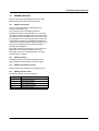
10.6
Process data access via XML
The integrated web server of the IL ETH BK DI8 DO4 2TXXC-PAC offers the option of accessing the process data of
the connected Inline terminals via a web page in XML
format.
You can access the web pages via a standard web browser.
For calling the XML pages with the process data enter the
address in the following format in the address line of the
browser:
Contains the number of connected Inline terminals,
including local I/Os. In the event of a bus error, the number
of the last known operable configuration is indicated.
DIAGNOSTIC_STATUS_REGISTER
Contains the INTERBUS status, represented by all bits of
the diagnostic status register. A detailed description can be
found in the diagnostic parameter register. Whenever an
error bit is set, the diagnostic parameter register is rewritten.
IL_BUS
Frame for the connected Inline terminals.
IL_MODULE
Frame for the data of an individual Inline terminal. The
terminals are numbered consecutively from one to a
maximum of 63.
MODULE_TYPE
Contains the terminal type. Possible types are DI, DO, DIO,
AI, AO, AIO, and PCP.
http:// <IP address>/procdata.xml
PD_CHANNELS
10.7
XML file structure
Frame for the entire XML file. The mandatory elements of
this frame are IL_BUS_TERMINAL and IL_BUS.
Number of process data channels in an Inline terminal. For
digital terminals the number of channels is equal to the
number of supported bits. For other terminals, the number of
process data words is indicated. Example: An IB IL AO 2
has two process data channels and an IB IL 24 DO 8 has
eight bits and eight process data channels.
IL_BUS_TERMINAL
PD_WORDS
This data area contains information on the entire Inline
station (bus coupler and all connected terminals). This data
area includes: TERMINAL_TYPE, the module name NAME,
the IP address IP_ADDRESS, the number of connected
terminals MODULE_NUMBER, the local bus diagnostic
status register DIAGNOSTIC_STATUS_REGISTER, and
the local bus diagnostic parameter register
DIAGNOSTIC_PARAMETER_REGISTER.
Number of process data words in an Inline terminal. Please
note that analog terminals always have the same number of
output and input words. An IB IL AO 2 therefore also has
two input channels and an IB IL AI 2 also has two output
channels.
The XML file contains different data areas:
IL_STATION
TERMINAL_TYPE
PD_IN
This area is used by all terminals that occupy input data. The
number of process data words depends on the terminal
type.
This area contains the designation of the bus coupler, which
is always IL ETH BK DI8 DO4.
NAME
Contains the user-specific station name. The station name
can be modified via WBM.
IP_ADDRESS
Contains the IP address of the station.
8501_en_01
PHOENIX CONTACT
15
IL ETH BK DI8 DO4 2TX-XC-PAC
Examples:
PD_OUT
a) Inline terminal with two active inputs
This area is used by all terminals with output data. The use
of bits is identical with that in "PD_IN".
<IL_MODULE number="1">
<MODULE_TYPE>DI</MODULE_TYPE>
<PD_CHANNELS>2</PD_CHANNELS>
<PD_WORDS>1</PD_WORDS>
<PD_IN word="1">3</PD_IN>
</IL_MODULE>
b) Inline terminal with two digital inputs and only the second
input is active
<IL_MODULE number="3">
<MODULE_TYPE>DI</MODULE_TYPE>
<PD_CHANNELS>2</PD_CHANNELS>
<PD_WORDS>1</PD_WORDS>
<PD_IN word="1">2</PD_IN>
</IL_MODULE>
In the event of an error in the Inline station, this is indicated
in the diagnostic registers. The D LED flashes on the bus
coupler. The process data is invalid because only internal
values are indicated, not the values on the local bus.
In order to make sure that only valid data is displayed, the
diagnostic register must also always be requested. The
same is true in the event of a faulty configuration. In this
case, the local bus does not run and only internal values can
be read in the XML file.
In the event of a peripheral fault, all data is valid, except for
the data of the faulty terminal.
c) Inline terminal with 16 digital inputs and the 13th and the
14th inputs are active
<IL_MODULE number="7">
<MODULE_TYPE>DI</MODULE_TYPE>
<PD_CHANNELS>16</PD_CHANNELS>
<PD_WORDS>1</PD_WORDS>
<PD_IN word="1">12288</PD_IN>
</IL_MODULE>
The input word returns the value 12288 (212 + 213).
d) Inline terminal with two analog inputs, only the first
channel being active (14970)
<IL_MODULE number="10">
<MODULE_TYPE>AI</MODULE_TYPE>
<PD_CHANNELS>2</PD_CHANNELS>
<PD_WORDS>2</PD_WORDS>
<PD_IN word="1">14970</PD_IN>
<PD_IN word="2">8</PD_IN>
<PD_OUT word="1">0</PD_OUT>
<PD_OUT word="2">0</PD_OUT>
</IL_MODULE>
8501_en_01
PHOENIX CONTACT
16
IL ETH BK DI8 DO4 2TX-XC-PAC
Figure 12
8501_en_01
Screen for XML data
PHOENIX CONTACT
17
IL ETH BK DI8 DO4 2TX-XC-PAC
11
Startup behavior of the bus coupler
11.2
Expert mode
The startup behavior of the bus coupler is specified via two
system parameters, plug and play mode (Var ID 2240hex)
and expert mode (Var ID 2275hex). By default upon delivery,
plug and play mode is activated and expert mode is
deactivated.
Expert mode inactive
11.1
If expert mode is active, the bus is not started automatically.
The user must set the station to the "RUN" state using the
appropriate firmware commands such as
CREATE_CONFIGURATION ,0710hex and
START_DATA_TRANSFER, 0701hex. The PP and CO
LEDs are not used.
Plug and play mode
Please note that the following description is valid
when expert mode is deactivated.
Plug and play mode active
If expert mode is deactivated (default upon delivery), the
bus coupler runs as described in 11.1.
Expert mode active
The IL ETH BK DI8 DO4 2TX-XC-PAC supports plug and
play mode (P&P). This mode enables Inline terminals
connected in the field to be started up using the bus coupler
without a higher-level computer. The P&P mode status
(active or inactive) is stored retentively on the bus coupler.
The current mode is displayed via the PP LED. In P&P
mode, the connected Inline terminals are detected and their
function checked. If this physical configuration is ready to
operate, it is started, however writing outputs is not enabled.
To enable writing outputs, P&P mode must be deactivated.
The deactivation of P&P mode is also the signal to save the
active configuration as the reference configuration.
Plug and play mode inactive
When P&P mode is deactivated, the reference configuration
is compared to the physical configuration. If they are the
same, the bus coupler is set to the "RUN" state.
If the reference configuration and the physical configuration
differ, the CO LED lights up and process data exchange is
not possible for safety reasons.
In order to operate the bus despite this, you have the
following two options:
1. Restore the original configuration so that the reference
configuration and the physical configuration are the
same again
2. Activate P&P mode and restart the bus coupler so that
the active physical configuration is accepted as the
reference configuration
8501_en_01
PHOENIX CONTACT
18
IL ETH BK DI8 DO4 2TX-XC-PAC
11.3
Possible combinations of modes
P&P mode
Inactive
Expert
mode
Inactive
Active
Inactive
Any
Active
11.4
Description/effect
Diagram
Normal case - the station sets valid configurations to the "RUN" state.
Process data exchange is possible.
The connected configuration is stored as the reference configuration and the
station is set to the "RUN" state. Process data cannot be written.
The bus is not started automatically, instead it waits for firmware commands
from the user.
Figure 13 on
page 19
Figure 14 on
page 19
Startup diagrams for the bus coupler
N o
P o w e r u p
P o w e r u p
L o a d a n d a c tiv a te
s a v e d c o n fig u r a tio n
R e a d in
c o n n e c te d c o n fig u r a tio n
C o n fig u r a tio n =
r e fe r e n c e c o n fig u r a tio n ?
N o
C a n c o n fig u r a tio n b e
o p e ra te d ?
Y e s
Y e s
S e P t o s w t a e tr i o U n p t o
"R U N " s ta te
S e P t o s w t a e tr i o U n p t o
"R U N " s ta te
S to
P P L E D
C O L E D
D L E D =
E rro r c a
lo c a l
d ia g n o s tic
o r in W
p
= O F F
= O N
fla s h in g
u s e in
b u s
r e g is te r s
B M
P P
C O
D L E
E
in
d ia g n
S ta tio n in
"R U N " s ta te
P P L E D = O F F
C O L E D = O F F
D L E D = O N
S to
L E D
L E D
D =
rro r c
lo c a
o s tic
p
= O N
= O N
fla s h in g
a u s e
l b u s
r e g is te r s
S ta tio n in
"R U N " s ta te
P P L E D = O N
C O L E D = O F F
D L E D = O N
7 2 7 5 A 0 1 1
7 2 7 5 A 0 1 0
Figure 13
"Standard" mode/
P&P and expert mode inactive
Figure 14
P&P mode active and
expert mode inactive
When expert mode is deactivated, the bus
coupler must be restarted for the change to take
effect.
8501_en_01
PHOENIX CONTACT
19
IL ETH BK DI8 DO4 2TX-XC-PAC
11.5
Changing and starting a configuration in P&P
mode
Ensure that plug and play mode is activated and
expert mode is deactivated.
The following steps must be carried out when changing an
existing configuration:
Switch off the supply voltage.
Change the configuration.
Switch on the supply voltage.
A configuration is started as shown in the flowchart (see
Figure 13 and Figure 14). During startup, please observe
the following:
– Once the bus coupler has been switched on, the
previously found configuration is read and started, as
long as no errors are present.
– All connected Inline devices are integrated in the active
configuration if the "DIAG" LEDs are continuously lit on
all terminals.
– To prevent the accidental use of the wrong
configuration, process data can only be accessed when
P&P mode has been deactivated.
When P&P mode is active, access to process
data is rejected with the error message 00A9hex
(ERR_PLUG_PLAY). The outputs of the entire
Inline station are reset in P&P mode.
P&P mode is activated either using WBM, the
Modbus command register or the "Set_Value"
command via Ethernet. Once P&P mode has
been switched off, the bus is only started if the
existing configuration and the reference
configuration are the same.
12
Monitoring functions
Monitoring functions with different features are available for
monitoring Ethernet communication.
– Process data watchdog (process data monitoring)
– Connection monitoring for Modbus (see "Modbus
connection timeout" on page 29) and DTI
The monitoring functions differ according to the features/
functions that need to be monitored. Depending on the
application requirements, the appropriate monitoring
function can be activated. By default upon delivery, the
process data watchdog is activated.
Monitoring
mechanism
Process data
watchdog
(process data
monitoring)
Connection
monitoring
for Modbus
and DTI
X
X
X
–
In the event of an error the system responds with a fault
response. The user determines the required fault response
mode.
12.1
Setting the required fault response mode
The required fault response mode can be set via web-based
management, by writing to Modbus register 2002 or using
the "Set_Value" service for variable 2277hex. The following
fault response modes are available:
Fault
response
mode
Standard
fault mode
Reset fault
mode
(default)
Hold last
state mode
8501_en_01
Monitoring...
... the
... the
... the
... proclient
indi- Ethernet cess data
applica- vidual connec- exchange
tion
chantion
nels
X
–
X
X
Value Function
0
All outputs are set to "0".
1
The digital outputs are set to "0".
The analog outputs are set to the
default value for the terminal.
All outputs keep their last value.
2
PHOENIX CONTACT
20
IL ETH BK DI8 DO4 2TX-XC-PAC
12.2
Process data watchdog/process data
monitoring
By default upon delivery, the process data
watchdog is activated with a 500 ms timeout.
NET FAIL
If there is no triggering during the timeout period, an error
occurred. Two responses follow:
– The selected fault response mode is executed.
– The Net Fail signal is set (the Net Fail LED is red).
The reason for setting the Net Fail signal is listed in the
reason code.
For safety reasons, the user cannot stop the watchdog once
it has been activated. If the user terminates the controlling
application, there is no watchdog triggering; when the
timeout period elapses, the Net Fail signal is set and the
selected fault response mode is executed. After the
watchdog has performed its task, the outputs are only
enabled again after acknowledgment.
By acknowledging the error, the watchdog is
restarted. This means that it must be triggered
during the timeout period, otherwise an error is
detected again.
Configuration of the process data watchdog
Figure 15
Process data monitoring configuration in WBM
Process data watchdog function
A process data watchdog is integrated into the
IL ETH BK DI8 DO4 2TX-XC-PAC bus coupler to avoid
uncontrolled setting/resetting of the I/O station outputs in the
event of an error.
If station outputs are set, the controlling process must be
able to access the station. In the event of an error, e.g.,
network line interrupted or function error in the controlling
process, the bus terminal can respond appropriately via the
process data watchdog. By default upon delivery, the
watchdog is activated with a 500 ms timeout. The first write
process activates the process data watchdog. The next
write process is expected during the timeout period (default:
500 ms). During error-free operation, the write process is
performed during the timeout period and the watchdog is
restarted (triggered).
Timeout periods can only be changed if the
watchdog is in the "INIT" state. The "INIT" state is
present:
– After power-up, as long as process data
exchange has not taken place
When a timeout has occurred and fault response
has been activated, and Net Fail has not yet been
acknowledged.
The process data watchdog timeout period can be
configured from 200 ms to 65000 ms. Timeout periods can
be set via web-based management, by writing to Modbus
register 2000 or using the "Set_Value" service for variable
2233hex.
Reading calls do not trigger the process data
watchdog.
8501_en_01
PHOENIX CONTACT
21
IL ETH BK DI8 DO4 2TX-XC-PAC
Deactivating the process data watchdog
The process data watchdog can only be deactivated if it is in
the "INIT" state. For deactivation, the timeout value is set to
"zero".
P o w e r u p
"IN IT " s ta te
W r ite _ O K /
C le a r N e tF a il
W a tc h d o g
T im e o u t > 0 ?
N o
Y e s
A C T IV E :
W r ite _ O K
Y e s
N o
W a tc h d o g tim e o u t e la p s e s
S e t N e t F a il
F a u lt r e s p o n s e
6 1 5 6 0 0 2 9
Figure 16
Status diagram of the process data watchdog
Possible reasons:
DDI_NF_TASK_CREAT_ERR
/* Error when starting a task */
DDI_NF_LISTENER_ERR
/* Listener task error */
DDI_NF_RECEIVER_ERR
/* Receiver task error */
DDI_NF_ACCEPT_ERR
/* Accept function error */
DDI_NF_ECHO_SERVER_ERR
/* Echo server task error */
DDI_NF_HOST_CONTROLLER_ERR
/* Host controller task error */
DDI_NF_DTI_TIMEOUT
/* DTI timeout occurred */
DDI_NF_HOST_TIMEOUT
/* Host timeout occurred */
DDI_NF_USER_TEST
/* NetFail set by user */
DDI_NF_CONN_ABORT
/* Connection aborted */
DDI_NF_INIT_ERR
/* Initialization error */
DDI_NF_DTI_WATCHDOG
/* Process data watchdog triggered */
DDI_NF_MBUS_TIMEOUT
/* Modbus timeout occurred */
0001hex
0002hex
0003hex
0004hex
0005hex
0006hex
0007hex
0008hex
0009hex
000Ahex
000Bhex
000Chex
000Dhex
Fault response acknowledgment
The Net Fail signal can be acknowledged via web-based
management via Modbus, by writing command 0002hex to
command register 2006 or using the "ETH_ClrNet
FailStatus" function.
Reasons for fault response
The reasons for a fault response and a set Net Fail signal
can be accessed via web-based management, Modbus
register 2004 or the "ETH_GetNet FailStatus" service.
8501_en_01
PHOENIX CONTACT
22
IL ETH BK DI8 DO4 2TX-XC-PAC
13
Modbus protocol
The bus coupler supports a Modbus/TCP server and a
Modbus/UDP server with the following features:
13.1
Modbus connections
The bus coupler supports up to eight Modbus/TCP
connections simultaneously.
The connection can access different addresses
simultaneously (static or dynamic tables). If a connection
over SDDI is used and simultaneously a connection to the
static table is opened, the SDDI connection is aborted with
the xxxx00AAhex error code. Only after a bus coupler reset
can the SDDI connection be reestablished. Simultaneous
connections over SDDI and Modbus dynamic tables are not
write-protected. Writing to static and dynamic tables is
protected with semaphores.
Since eight connections are supported, a connection can
quickly be restored. This means that the client can
successfully restore an interrupted Modbus connection.
The UDP server is wireless.
13.2
Modbus interface
The Modbus interface according to standard port 502
supports Modbus communication via the bus coupler.
13.3
Modbus conformance classes
The bus coupler supports Modbus conformance class 0.
13.4
Modbus function codes
The following function codes are supported:
Code no.
fc3
fc4
fc6
fc16
fc23
8501_en_01
Function code
Read multiple registers
Read input registers
Write single register
Write multiple registers
Read/write registers
PHOENIX CONTACT
23
IL ETH BK DI8 DO4 2TX-XC-PAC
13.5
Modbus tables
Special registers
Modbus register table Access
(16-bit word)
1280
Read/write
2000
Read/write
2002
Read/write
2004
Read/write
2006
Read/write
PCP
Modbus register table Access
(16-bit word)
6020 - 6173
Read/write
Diagnostics
Modbus register table Access
(16-bit word)
7996
Read only
7997
Read only
7998
Read only
7999
Read only
Process data (dynamic table)
Modbus register table Access
(16-bit word)
8000
Read only
8001-(8000+x)
Read only
(8001+x)
Read/write
(8002+x)-(8001+x+y)
Read/write
Function
Modbus connection monitoring timeout
Process data watchdog timeout
Fault response mode
Net Fail reason
Command register
Function
See Modbus PCP registers on page 30
Function
Status register
Local bus diagnostic status register
Local bus diagnostic parameter register 1
Local bus diagnostic parameter register 2
Function
Local digital inputs
Bus inputs (x words)
Local digital outputs
Bus outputs (y words)
Process data (static table)
Modbus register table Internal
(16-bit word)
IL ETH BK DI8 DO4 2
TX-XC-PAC tables
(16-bit word)
0 - 191
%I1 - 192
192 - 383
%AI1 - 192
384 - 575
%Q1 - 192
576 - 767
%AQ1 - 192
8501_en_01
Access
Read only
Read only
Read/write
Read/write
Function
Digital inputs
Analog inputs
Digital outputs
Analog outputs
PHOENIX CONTACT
24
IL ETH BK DI8 DO4 2TX-XC-PAC
AO2
AO1
AI2
AI2
DI2
DI8
DO2
DO8
DI8 ETH BK
DO4 ETH BK
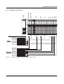
Assignment of process data
ETH BK
13.6
ETHERNET
RESET
LNK1
ACT1
X1
LNK2
ACT2
X2
Modbus register/location of process data
DATA IN
DATA OUT
Figure 17
8501_en_01
Address 8000
Address 8001
Address 8002
Address 8003
Address 8004
Address 8005
Address 8006
Address 8007
Address 8008
Address 8009
Address 8010
Address 8011
Address 8012
Address 8013
Address 8014
Address 8015
Address 8016
Address 8017
Address 8018
xxxxxxxx
xxxxxxxx
xx
Channel 1 value
Channel 2 value
Channel 1 value
Channel 2 value
Channel 1 status
Channel 2 status
xxxx
xxxxxxxx
xx
Channel 1 parameter
Channel 2 parameter
Channel 1 parameter
Channel 2 parameter
Channel 1 value
Channel 1 value
Channel 2 value
7275A014
Example for the location of process data in dynamic tables
PHOENIX CONTACT
25
AO2
AO1
AI2
AI2
DI2
DI8
DO2
DO8
DI8 ETH BK
ETH BK
DO4 ETH BK
IL ETH BK DI8 DO4 2TX-XC-PAC
ETHERNET
RESET
LNK1
ACT1
X1
LNK2
ACT2
X2
Digital IN
Address 0000
Address 0001
Address 0002
xxxxxxxx
xxxxxxxx
xx
Address 0191
Analog IN
Address 0192
Address 0193
Address 0194
Address 0195
Address 0196
Address 0197
Channel 1 value
Channel 2 value
Channel 1 value
Channel 2 value
Channel 1 status
Channel 2 status
Address 0383
Digital OUT Address 0384
x xxx
Address 0385
Address 0386
xxxxxxxx
xx
Address 0575
Analog OUT Address 0576
Address 0577
Address 0578
Address 0579
Address 0580
Address 0581
Address 0582
Channel 1 parameter
Channel 2 parameter
Channel 1 parameter
Channel 2 parameter
Channel 1 value
Channel 1 value
Channel 2 value
7275A015
Address 0767
Figure 18
8501_en_01
Example for the location of process data in static tables
PHOENIX CONTACT
26
IL ETH BK DI8 DO4 2TX-XC-PAC
13.7
Diagnostic registers
Status register
Address:
– Modbus: Register 7996
Using the Ethernet host controller, e.g., PLC, the user can
read current diagnostic information from the network
interface status word without the need for configuration
software.
Only the two least significant bits (bit 0 and bit 1) have a
function. The bits of bit 2 to bit 15 are reserved.
– Bit 0 = 0: An error occurred
(e.g., a bit in the diagnostic register is set).
– Bit 0 = 1: No error
– Bit 1 = 0: No Net Fail
– Bit 1 = 1: Net Fail present
This results in the following values for the status word:
Register
contents
0000hex
0001hex
0002hex
State
Bit
5
6
7
Constant
RUN_BIT
ACTIVE_BIT
READY_BIT
Meaning
Exchanging data cycles
Local bus master ACTIVE
Local bus master READY, selftest
completed
Operating indicators: READY, ACTIVE, RUN
The READY, ACTIVE, and RUN operating indicators show
the current state of the local bus system. The diagnostic
parameter register is not used.
After the selftest, the local bus master is ready for operation.
The READY indicator bit is set (READY = 1).
If the local bus master has been configured and the
configuration frame activated without errors, the system
indicates it is active. The READY and ACTIVE indicator bits
are set (READY = 1, ACTIVE = 1).
In addition, the RUN indicator bit is set when data exchange
is started (READY = 1, ACTIVE = 1 and RUN = 1).
Errors are indicated until they are acknowledged.
An error occurred (e.g., a bit in the
diagnostic register is set).
No errors have occurred.
A Net Fail occurred.
Local bus diagnostic status register
Address:
– Modbus: Register 7997
Each bit in the local bus diagnostic status register is
assigned a state of the local bus master on the bus coupler.
The states in the error bits (USER, PF, BUS, CTRL) are
described in greater detail using the diagnostic parameter
register. Whenever one of the error bits described above is
set, the diagnostic parameter register is rewritten.
Otherwise, the diagnostic parameter register has the value
0000hex.
Bit
0
1
2
3
4
Constant
USER_BIT
PF_BIT
Meaning
Application program error
Local bus device detected a
peripheral fault
BUS_BIT
Error on local bus
CTRL_BIT
Local bus master has an internal
error
DETECT_BIT Error localization
("LOOK FOR FAIL")
8501_en_01
PHOENIX CONTACT
27
IL ETH BK DI8 DO4 2TX-XC-PAC
Error indicators: DETECT, CTRL, BUS, PF, USER
Local bus diagnostic parameter register 1
The DETECT error bit shows that an error is preventing
further operation of the local bus (DETECT = 1). The
outputs return to the set state, see page 20. The diagnostic
routine searches for the error cause.
Address:
– Modbus: Register 7998
Once the error cause has been detected, the DETECT error
bit will be reset (DETECT = 0) and the error indicated in the
USER, PF, BUS and CTRL bits. The diagnostic parameter
register and the extended diagnostic parameter register
provide a detailed description of the error cause.
For detected local bus errors, the local bus diagnostic
parameter register contains the error location:
Device number of device, e.g., "0.3" for bus segment 0;
device 3,
Error location, e.g., device number 0.3
Error with local bus shutdown
Error bit/location
CTRL = 1
Probably local bus master/
hardware error.
BUS = 1
S e g m e n t n u m b e r
Contents of the
diagnostic
parameter register
Error code
0
0
7
3
n + 1
n
0
7
0
7 2 7 5 a 0 0 7
Figure 19
Contents of the local bus diagnostic parameter
register (example)
Error location
Local bus diagnostic parameter register 2
Error on a local bus segment.
Error without local bus shutdown
Error bit/location
0
P o s itio n in th e s e g m e n t
PF = 1
Contents of the
diagnostic
parameter register
Error location
Fault on the peripheral side of a
local bus device:
– Short circuit at the output
– Sensor/actuator supply not
present
USER = 1
Error code
Address:
– Modbus: Register 7999
Local bus diagnostic parameter register 2 contains
additional information about the error codes.
User error, e.g., due to incorrect
parameters
8501_en_01
PHOENIX CONTACT
28
IL ETH BK DI8 DO4 2TX-XC-PAC
13.8
Special registers
Modbus connection timeout
Modbus: Register 1280
A monitoring mechanism can be activated for every
Modbus/TCP connection in order for the bus coupler to
detect an error on the network (e.g., faulty cable) or in the
client (operating system crash or error in the TCP/IP
protocol stack) and respond accordingly. The monitoring
mechanism is activated via the relevant TCP connection
upon the first read or write procedure.
To change the timeout value for the relevant TCP
connection, write the new timeout value to the timeout table
to the special address 1280 using functions "fc 6" or "fc 16".
The value of this entry is the value of the timeout table. The
time is specified in milliseconds in the range from 200 ms to
65000 ms.
A timeout value of "0" deactivates the monitoring function.
Values between 1 ms and 199 ms, and values greater than
65000 ms generate exception response 3
(ILLEGAL DATA VALUE).
Net Fail reason
Address:
– Modbus: Register 2004
This register can be used to read the reason after setting the
Net Fail signal. If there is no Net Fail signal, the register is 0.
Command register
–
Modbus: Register 2006
The network interface command register can be used to
transmit commands with basic functions to the bus coupler
using the Ethernet host controller, e.g., PLC.
15 14 13 12 11 10 9 8 7 6 5 4 3 2 1 0
X X X
Reserved bits
Clear peripheral fault
Clear NetFail
Plug and play
Figure 20
61560030
Command word
Connection monitoring with the new timeout
values is only activated after a Modbus/TCP
function has been executed on the relevant TCP
connection.
After the first access by a Modbus/TCP function, all other
access must be carried out using the entered timeout value.
Otherwise, fault response mode is activated and the
Modbus/TCP connection is disabled.
Process data watchdog timeout
–
Modbus: Register 2000
Setting or reading the timeout value for the process data
watchdog. The time is specified in milliseconds in the range
from 200 ms to 65000 ms. A timeout value of "0" deactivates
the watchdog.
Fault response mode
–
Modbus: Register 2002
Setting or reading the fault response mode. For information
on fault response mode settings, please refer to Section
"Setting the required fault response mode" on page 20.
8501_en_01
PHOENIX CONTACT
29
IL ETH BK DI8 DO4 2TX-XC-PAC
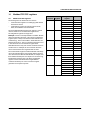
14
Modbus/TCP PCP registers
14.1
Modbus/TCP PCP registers
The PCP registers are divided into two classes:
– Communication registers for exchanging data with the
desired PCP device
– Configuration registers for selecting the invoke ID,
index, and subindex of the PCP device
The IL ETH BK DI8 DO4 2TX-XC-PAC supports 16 PCP
devices, therefore 16 communication registers and
24 configuration registers are supported.
Example: In order to read object 5FE0hex of an IB IL RS 232
with communication reference 4, first set the configuration
registers (6041 - 6043) to the desired values with the fc16
command (e.g., 6041 index: 5FE0hex, 6042 subindex: 0hex,
6043 invoke ID: 0hex). The fc3 command can then be used
to read 29 words via communication register 6040.
Communication
reference register
CR 2
6020
CR 3
CR 4
8501_en_01
6021
6022
6023
6024 - 6029
Index
Subindex
Invoke ID
Reserved
6031
6032
6033
6034 - 6039
Index
Subindex
Invoke ID
Reserved
6041
6042
6043
6044 - 6049
Index
Subindex
Invoke ID
Reserved
...
...
6161
6162
6163
6164 - 6169
Index
Subindex
Invoke ID
Reserved
6171
6172
6173
6174 - 6179
Index
Subindex
Invoke ID
Reserved
6040
...
...
CR 16
6160
CR 17
Note
6030
A Modbus function is only ever used for read/write access to
a PCP index. For example, the fc3 command cannot be
used to read 20 words from registers 6020 to 6039.
The communication register contains a different value range
due to the selected values of the register and the terminal
used. Therefore, the IB IL RS 232 terminal, for example, has
three different PCP objects: two objects are one word long,
but the third is 29 words long. The three configuration
registers can be read/written with a single Modbus
command. An attempt to access a reserved register
generates an exception response.
Configuration
register
6170
PHOENIX CONTACT
30
IL ETH BK DI8 DO4 2TX-XC-PAC
14.2
Transmitting an odd number of data bytes via
PCP (firmware version 1.30 or later)
The Modbus functions allow you to exchange data words
with PCP devices.
15
Device Driver Interface (DDI)
The IL ETH BK DI8 DO4 2TX-XC-PAC bus coupler
supports access via the Device Driver Interface (DDI).
A driver for Windows NT, Windows 2000, and
Windows XP can be downloaded at
www.phoenixcontact.de/catalog under the name
"Ethernet Driver 2.0. exe". Drivers for other
operating systems are available from
Phoenix Contact on request.
Using bus couplers with firmware version <1.30, it was not
possible to access odd-length communication objects.
Firmware version 1.30 includes the “Ignore last byte” option.
This option enables odd-length communication objects to
be transmitted.
To transmit an odd number of PCP bytes, set bit 0 in the high
byte of the “Invoke-ID” PCP configuration register. This
leads to the fact that the low byte of the last Modbus data
word written or to be read is excluded from PCP
transmission.
The PCP-Invoke-ID is an 8-bit date, thus allowing
the high byte of this Modbus register to be used
for this function.
This change is backward compatible, since older
firmware versions do not evaluate the bit.
Example 1: Writing 15 data bytes to the 5FE0hex object of
the PCP device with communication reference 2 (CR 2)
Initialize the configuration register of CR 2:
Modbus
address
6021
Register name
6022
CR 2 subindex
0
6023
CR 2 Invoke-ID
100
CR 2 index
Value
[hex]
5FE0
Eight data words will then be written to the CR 2 communication register (Modbus address 6020).
In this example, the low byte of the last data word written to
the Modbus address 6020 will not be transmitted to the PCP
device with CR 2.
Example 2: Reading 11 data bytes from the 5FE0(hex) object of the PCP device with communication reference 4
(CR 4)
Initialize the configuration register of CR 4:
The following services are supported:
15.1
–
–
–
–
–
–
–
–
15.2
–
–
–
–
–
–
–
Register name
Value
[hex]
5FE0
6042
CR 4 subindex
0
6043
CR 4 Invoke-ID
100
–
–
Services for remote access to the DDI
DDI_DevOpenNode ( )
DDI_DevCloseNode ( )
DDI_DTI_ReadData ( )
DDI_DTI_WriteData ( )
DDI_DTI_ReadWriteData ( )
DDI_MXI_SndMessage ( )
DDI_MXI_RcvMessage ( )
GetIBSDiagnostic ( )
Connection and error monitoring
ETH_SetDTITimeoutCtrl ( )
ETH_ClearDTITimeoutCtrl ( )
ETH_SetNet Fail ( )
ETH_GetNet FailStatus ( )
ETH_ClrNet FailStatus ( )
ETH_SetNet FailMode ( )
ETH_GetNet FailMode ( )
15.3
Modbus
address
6041
CR 4 index
Using this interface requires the appropriate driver to be
installed on the host. For a detailed description of the
services, please refer to the "Driver reference manual for
G4-based controller boards using PC bus and Ethernet",
see "Documentation" on page 3.
Services for process data monitoring
ETH_ActivatePDinMonitoring ( )
ETH_DeactivatePDinMonitoring ( )
Six data words will then be read from the CR 4 communication register (Modbus address 6040).
In this example, the last data byte read by the PCP device
will be transmitted in the high byte of the last Modbus data
word.
8501_en_01
PHOENIX CONTACT
31
IL ETH BK DI8 DO4 2TX-XC-PAC
16
Firmware services
As it is not necessary to use each firmware service in both
operating modes (expert mode active/inactive), the
following table indicates the assignment of the services to
the operating modes. If the services are not used as
specified in the table, this may cause the firmware to behave
as follows:
Code
0309hex
Services
Read_Configuration
030Bhex
Complete_Read_Configuration
0315hex
Read_Device_State
0316hex
032Ahex
032Bhex
Get_Error_Info
Get_Version_Info
Get_Diag_Info
0351hex
0714hex
Read_Value
Control_Device_Function
0750hex
0760hex
0956hex
Set_Value
Confirm_Diagnostics
Reset_Controller_Board
1.
2.
The service is not permitted in this mode and is rejected
with a negative acknowledgment
The service is executed and terminated with a positive
acknowledgment. The effect of this service is removed
by the firmware. Supported firmware services that can
be used in every operating mode:
Function
Reads various entries of the configuration directory
Used_Attributes: 0002hex = Device code
Reads all device data for a configuration
Used_Attributes: 0002hex = Device code
Reads status of local bus devices
Device_State_Mask: 0008hex = Peripheral fault
Requests additional error information
Reads version information
Reads local bus counters
Diag_Info_Attr: 0004hex = Global_Count
Reads system parameters
Sends control commands to local bus devices
Device_Function:
0003hex = Conf_Dev_Err
0004hex = Conf_Dev_Err_All
Assigns new values to system parameters
Updates the diagnostic display and registers
Resets the controller board
Supported firmware services that are only available in expert mode:
Code
0306hex
0307hex
Services
Initiate_Load_Configuration
Load_Configuration
030Ahex
Complete_Load_Configuration
0308hex
Terminate_Load_Configuration
030Chex
030Ehex
0701hex
0710hex
0711hex
1303hex
Delete_Configuration
Control_Parameterization
Start_Data_Transfer
Create_Configuration
Activate_Configuration
Alarm_Stop
Function
Loads a configuration frame (extension not supported)
Transmits the device data for a configuration
Used_Attributes: 0002hex = Device code
Transmits all device data for a configuration
Used_Attributes: 0002hex = Device code
Terminates the transmission of configuration data
only for automatic parameterization
Deletes a configuration
Starts or ends the parameterization phase
Starts data transmission
Reads in the connected configuration
Compares the saved and connected configuration
Resets the local bus
For additional information about firmware services, please refer to the IBS SYS FW G4 UM E user manual.
8501_en_01
PHOENIX CONTACT
32
IL ETH BK DI8 DO4 2TX-XC-PAC
System parameters for the "Set_Value" (750hex) and "Read_Value" (351hex) services
Variable_ID
0104hex
0105hex
010Dhex
2216hex
2240hex
System parameter
Diagnostic status register (16-bit word)
Diagnostic parameter register 1 (16-bit word)
Diagnostic parameter register 2 (16-bit word)
Current PD cycle time (32-bit word)
Plug and play mode (32-bit word)
2275hex
Expert mode (32-bit word)
2277hex
2293hex
Fault response mode (32-bit word)
Process data watchdog timeout (32-bit word)
17
PCP communication
17.1
Transmission of parameter data
Intelligent devices such as frequency inverters or controllers
exchange process data with each other and also exchange
larger volumes of data with the control system. Such data
can, for example, be used for the startup phase of a
machine. This type of parameter data rarely changes and is
transmitted when necessary.
The INTERBUS protocol can transmit process data and
complex data records (parameter data) simultaneously. The
comprehensive parameter data is divided into smaller units,
transmitted and then recombined.
In the INTERBUS system, the Peripherals Communication
Protocol (PCP) divides the parameter data into individual
segments. After transmission it recombines the data. PCP
refers to the protocol software. This software provides the
necessary services for connection establishment and
connection abort, etc.
Value/note
Read only
Read only
Read only
Read only
0: Plug and play mode deactivated
1: Plug and play mode activated
0: Expert mode deactivated
1: Expert mode activated
See page 20
See page 21
17.2
Supported PCP commands
The MXI interface of the DDI can be used to send the
following PCP commands.
Service
Initiate_Request
Abort_Request
Read_Request
Write_Request
Information_Report_Request
Status_Request
Identify_Request
Load_Kbl_Par_Loc_Request
Read_Kbl_Loc_Request
Service code
008Bhex
088Dhex
0081hex
0082hex
0885hex
0083hex
0087hex
0264hex
0203hex
For detailed information on PCP communication,
please refer to the IBS SYS PCP G4 UM E user
manual.
Please note that a maximum of 16 PCP terminals
can be connected to a bus coupler.
8501_en_01
PHOENIX CONTACT
33
IL ETH BK DI8 DO4 2TX-XC-PAC
17.3
Configuration of the PCP PDU size
The standard PDU size for communication with all
Phoenix Contact Inline devices is 64 bytes in the transmit
and receive direction.
System couplers such as the ILC 200 UNI have
configurable PDU sizes. If a different size will be configured
and an IL ETH BK DI8 DO4 2TX-XC-PAC is used to
communicate with the size, the bus coupler must also be
configured to the new values.
18
Simple Network Management
Protocol (SNMP)
The bus coupler supports SNMP v1 and v2c.
Management Information Base - MIB
The corresponding latest MIBs are available on
the Internet at www.phoenixcontact.de/catalog.
For the object descriptions, please refer to the ASN1
descriptions of this product. These can be found on the
Internet at www.phoenixcontact.net/catalog.
The password for read access is “public” and cannot be
changed. By default upon delivery, the password for read/
write access is “private” and can be modified at any time.
Figure 21
8501_en_01
PCP configuration in web-based management
PHOENIX CONTACT
34