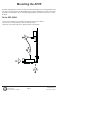
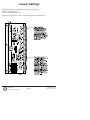
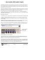
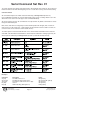
1
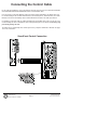
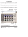
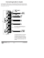
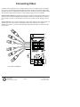
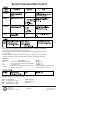
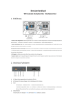
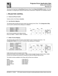
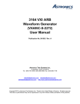
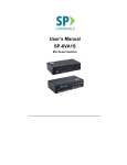
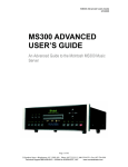
SP3-AFVP+
Audio Follow Video Preamp Switcher
Installation Guide
The Audio Follow Video Preamplifier (AFVP), for use with the SP Controls SmartPanel™ or independently, adds a stereo 5x1 audio switcher and pre-amplifier. It provides volume control through attenuation. Gain and EQ settings are set in
SmartPanel configuration.
Video inputs and outputs (female
BNC) - may be configured as a
4x1 video switch or a 2x1
S-Video switch
RS-485 control port for
standalone operation
RS-232 control port for
standalone operation
Audio Output connector
Can be balanced or unbalanced
Mix Input (mono)
Connect the output of wireless mic or
mic mixer here
Aux Audio Input (Input 5)
(for use with CD Players,
tape decks, etc.)
Audio Inputs 1 - 4
These inputs follow
input selection on the
SmartPanel
SP Controls Inc.
930 Linden Ave.
S. San Francisco, CA 94080
Page 1
email : [email protected]
web: spcontrols.com
phone: (877) 367-8444
Important Safety Instructions
1) Read these instructions.
2) Keep these instructions.
3) Heed all warnings.
4) Follow all instructions.
5) Do not use this apparatus near water.
6) Clean only with a dry cloth.
7) Do not block any ventilation openings. Install in accordance with the manufacturer's instructions.
8) Do not install near any heat sources such as radiators, heat registers, stoves, or other apparatus
(including amplifiers) that produce heat.
9) Do not defeat the safety purpose of the polarized or grounding type plug. A polarized plug has two
blades with one wider than the other. A grounding type plug has two blades and a third grounding
prong. The wide blade or the third prong is provided for your safety. When the provided plug does not fit
into your outlet, consult an electrician for replacement of the obsolete outlet.
10) Protect the power cord from being walked on or pinched particularly at plugs, convenience receptacles, and the point where they exit from the apparatus.
11) Only use attachments/accessories specified by the manufacturer.
12) Use only with a cart, stand, tripod, bracket, or table specified by the manufacturer, or sold with the
apparatus. When a cart is used, use caution when moving the cart/apparatus combination to avoid
injury from tip-over.
13) Unplug this apparatus during lightning storms or when unused for long periods of time.
14) Refer all servicing to qualified service personnel. Servicing is required when the apparatus has been
damaged in any way, such as power supply cord or plug is damaged, liquid has been spilled or objects
have fallen into the apparatus, the apparatus has been exposed to rain or moisture, does not operate
normally, or has been dropped.
WARNING - To Reduce the Risk of Fire Or Electric Shock, Do Not Expose This Apparatus
To Rain Or Moisture.
Apparatus shall not be exposed to dripping or splashing and no objects filled with liquids,
such as vases, shall be placed on the apparatus.
FCC Compliance
This equipment generates radio frequency energy and if not installed in accordance with the manufacturer's instructions may cause radio interference.
This equipment complies with part 15, Subpart J of the FCC rules for a Class A computing device. This
equipment also complies with the Class A limits for radio noise emission from digital apparatus set out in
the Radio Interference Regulation of the Canadian Department of Communications. These above rules
are designed to provide reasonable protection against such interference when operating the equipment
in a commercial environment. If operation of this equipment in a residential area causes radio frequency
interference, the user and not SP Controls, Inc., will be responsible.
Changes or modifications made to this equipment not expressly approved by SP Controls, Inc., could
void the user's authority to operate the equipment.
SP Controls Inc.
930 Linden Ave.
S. San Francisco, CA 94080
Page 2
email : [email protected]
web: spcontrols.com
phone: (877) 367-8444
Connecting the Control Cable
For use with the SmartPanel, connect the AFVP to the back of the Panel on the header labeled AUDIO
FOLLOW VIDEO SWITCHER EXPANSION with the included ribbon cable.
If it is necessary to extend the distance between the AFVP and the SmartPanel, the ribbon cable may
be extended using the SP Controls AFVP Extender (not included, part no. SP2-AFVP-EXT). The AFVP
Extender converts the intermediary cable to CAT5 and allows extension of the cable up to 50 feet.
It is possible to extend the cable by cutting and splicing an intermediate cable in-line. We do not recommend extending the cable in this fashion, as the cable provides power to the AFVP and miswiring may
permanently damage the unit.
The AFVP can be controlled by other control systems or by computer via RS-232 or RS-485. See page
12 for more information.
SmartPanel Control Connection
SP Controls Inc.
930 Linden Ave.
S. San Francisco, CA 94080
Page 3
email : [email protected]
web: spcontrols.com
phone: (877) 367-8444
Configuration
Each audio input may be seperately configured for bass, treble, and gain. If the AFVP is used with the
SmartPanel control system, configuration is made on the SmartPanel, and settings are stored on the
SmartPanel memory. To configure the AFVP with a SmartPanel, connect the AFVP to the SmartPanel
prior to connecting to the SmartPanel configuration port with the RS-232 serial configuration cable. For
general information on configuring the SmartPanel, see the SmartPanel Configuration and Installation
Guide.
Settings can also be made in stand-alone mode using serial commands through either the RS-232 or
RS-485 control ports. See pages 12 and following for more information.
To configure audio with the SmartPanel, connect the AFVP to the SmartPanel prior to configuring the
Panel with the SP Controls Product Configuration Utility. Configuration is made on the Configure Audio
configuration page.
0-10dB true Gain
per channel*
Enable Aux Audio 5th Input
Without Peripheral Switch
(see page 10 for more information)
0-12dB bass/treble
per channel
Defeat EQ Settings
(disables EQ settings)
*Note: Advanced users can achieve up to 10dB of additional gain if needed;
contact SP Controls Technical Support for more information
SP Controls Inc.
930 Linden Ave.
S. San Francisco, CA 94080
Set Startup Volume
(percentage of max.)
Page 4
Defeat Preamp
(disable AFVP volume
control and gain settings)
email : [email protected]
web: spcontrols.com
phone: (877) 367-8444
Connecting Audio to Inputs
Five audio inputs are unbalanced stereo. They will typically be attached to a source device such as a
VCR or DVD player, or to patch points on the wall. Each input generally takes two wires and a shield.
One wire with two conductors and a shield may be used as long as the ground is attached on both the
left and right at the source end.
The 5th balanced input is available for use
with Aux Audio configuration. See page 10
for more information.
The Mix input is ALWAYS on. It is mixed into
the output without any volume control. It is
intended for use with a room mic system.
The input takes a balanced line level output
from sources like wireless mic receivers and
mic mixers. You cannot wire a mic directly
to this input without going through a mic
preamp.
SP Controls Inc.
930 Linden Ave.
S. San Francisco, CA 94080
Page 5
email : [email protected]
web: spcontrols.com
phone: (877) 367-8444
Connecting Audio to Output
Most self-powered speakers and consumer level audio amplifiers have unbalanced inputs (usually RCA
or 1/8" mini jack connectors). Professional audio amplifiers generally accept balanced inputs (XLR connectors).
Unbalanced
Balanced
SP Controls Inc.
930 Linden Ave.
S. San Francisco, CA 94080
Page 6
email : [email protected]
web: spcontrols.com
phone: (877) 367-8444
Connecting Video
The AFVP can be configured as a 4x1 composite switcher or as a 2x1 S-Video switcher. The diagram
on the cover of the AFVP labels inputs and outputs for both the S-Video and Composite Video modes.
By default, the AFVP is configured for Composite Video mode. The AFVP may be set to S-Video switching mode with a simple jumper setting. See Jumper Settings on page 9 for more information.
Composite Video Switching: If the AFVP is configured for Composite Video switching (default), video
inputs 1-4 will be switched to VIDEO OUT following input selection on the SmartPanel. For example, if
the user presses selection 1 (left-most button on the Panel), then VID IN 1 will be switched to the output.
S-Video Switching: If the Preamp is configured to S-Video mode, SVID IN 1 will be switched to the output when input 1 or 3 is selected on the SmartPanel. SVID 2 will be switched to the output on
SmartPanel selections 2 or 4. Each S-Video input and output requires 2 BNCs, for a total of 4 conductors per signal.
Female BNC Inputs/Outputs
SP Controls Inc.
930 Linden Ave.
S. San Francisco, CA 94080
Page 7
email : [email protected]
web: spcontrols.com
phone: (877) 367-8444
Mounting the AFVP
The AFVP was designed to mount to the back of the SP2-CHAS with the three screws provided. There
is no way to mount the AFVP to the SP2-SMCHAS due to its size limitations. If the AFVP is not mounted directly to the SmartPanel, use the mounting wings provided on the bottom of the device to mount
the AFVP.
To the SP2-CHAS
1. Place the Preamp above the metal lip on the bottom rear side of the chassis.
2. Use the three screws provided to secure the Preamp in place.
3. Attach the 8-pin control cable to the chassis and then to the Preamp.
SP Controls Inc.
930 Linden Ave.
S. San Francisco, CA 94080
Page 8
email : [email protected]
web: spcontrols.com
phone: (877) 367-8444
Jumper Settings
Through hardware jumper configuration the AFVP can be configured to:
1) Stereo or Mono mode, and
2) Video or S-Video switching mode.
To configure the AFVP to these modes, simply install the jumpers as shown below.
SP Controls Inc.
930 Linden Ave.
S. San Francisco, CA 94080
Page 9
email : [email protected]
web: spcontrols.com
phone: (877) 367-8444
Aux Audio (5th Audio Input)
A SmartPanel using an AFVP may be configured to use Aux Audio mode, allowing switching audio to a
5th stereo audio channel on the preamp. The SmartPanel volume control may be used to control volume of an audio-only device without turning the projector on. This can be useful for audio control of an
audio-only device such as a CD player.
Tip: The audio output from a DVD player can be split to two audio inputs on the preamp - the input corresponding to the SmartPanel input and the 5th input on the AFVP. The DVD player can then be used
as an audio-only device to play audio CDs in addition to its use as a video device.
Aux Audio mode can be accessed with a Aux Audio peripheral (part no. SLB-MINI-AUXAUDIO) or
directly with the SmartPanel interface. SP Controls recommends use of the Aux Audio peripheral switch
as it provides a clearer interface
SmartPanel Configuration
The SmartPanel must be configured to use Aux Audio with the SP Controls Product Configuration Utility.
Installations using the Aux Audio peripheral switch: Go to the Configuration Utility page labeled
Configure Wiring. In the pull-down menu labeled Accessories select the AuxAudio option (see illustration on next page).
Installations not using the Aux Audio peripheral switch: Go to the Configuration Utility tab labeled
Configure Audio. Select the box labeled Enable Aux Audio (see illustration below).
When you have selected the correct configuration, download the settings to the SmartPanel. For more
information on configuring the SmartPanel, see the SmartPanel Installation and Configuration Guide.
SmartPanel Configuration
(Aux Audio without
Peripheral Switch)
Aux Audio Without the Peripheral Switch
Activating Aux Audio mode on a SmartPanel without a peripheral switch will activate the SmartPanel
volume control for an audio-only device without turning on the projector. Without the switch, it is not
possible to select the 5th input on the preamp while the projector is on.
To activate Aux Audio mode while the SmartPanel and projector are off, press the VOLUME UP button
on the SmartPanel. This will switch the AFVP preamp to the 5th input, activate the SmartPanel volume
control display, and allow volume control from the SmartPanel as normal. The projector will remain off.
To return the SmartPanel to its normal off state, press the POWER OFF button.
SP Controls Inc.
930 Linden Ave.
S. San Francisco, CA 94080
Page 10
email : [email protected]
web: spcontrols.com
phone: (877) 367-8444
Aux Audio Cont’d
Aux Audio With the
Peripheral Switch
Aux Audio mode is best
implemented with the Aux
Audio peripheral switch
(part no. SLB-MINI-AUXAUDIO). This modular
switch is designed to
mount into the frame of
the Large Chassis
SmartPanel (SP2-CHAS),
or in the mini-module
cutouts of the SmartBox+
(SLB-SBOX+),
SmartDrawer (SLB1050B), or Rack Mount
kit with Mini-Mod CutOuts (SP2-RACKSMMOD). The Aux Audio
peripheral switch should
be wired to the
SmartPanel as illustrated below.
The SmartPanel must be configured to use Aux Audio mode with the SP
Controls Product Configuration Utility (see SmartPanel Configuration
above).
SmartPanel Configuration
(Aux Audio with Peripheral
Switch)
Wiring Aux Audio
Peripheral Switch to
SmartPanel
Red
Black
White
Once the Aux Audio peripheral switch has been installed and the SmartPanel has been configured
for its use, press the switch to activate Aux Audio mode. The button on the Aux Audio switch will illuminate and the AFVP preamp will switch to the 5th stereo input. If the SmartPanel and projector are
off when the Aux Audio switch is pressed, the SmartPanel volume display will activate and you will
be able to control volume on the audio-only device normally without powering on the projector. If the
SmartPanel is on, the projector input will remain as selected, but audio will switch to the 5th audio
input.
Press the Aux Audio button again to return the SmartPanel to its normal state. If the projector is off,
the volume control will become inactive and the AFVP preamp output will mute. If the projector is
on, the SP3-AFVP+ preamp will return to the audio output corresponding to the selected input on
the SmartPanel.
SP Controls Inc.
930 Linden Ave.
S. San Francisco, CA 94080
Page 11
email : [email protected]
web: spcontrols.com
phone: (877) 367-8444
Serial Control Connection
The AFVP is fully controllable via RS-232 and RS-485 and can be integrated easily with a PC or any
control system. Connection is via Stereo 1/8" mini connector.
Command device control port settings should be configured as follows:
BAUD Rate: 9600 bps
Data: 8 bits
Parity Bit: None
Stop Bit: 1
Flow Control: None
Wire the control device to a stereo 1/8" mini connector as follows:
Female DB9
PIN 2
PIN 3
PIN 5
Signal Type
TX
RX
GND
1/8” Connector
TIP
RING
SLEEVE
RS-485 port
(from the perspective of
the control device)
Female DB9
to PC or Control Device
1/8” Stereo Mini to
RS-232 port on AFVP
RS-232 may be wired directly to a control device, or wired to
a female DB9 as shown for connection to a PC Com Port.
SP Controls Inc.
930 Linden Ave.
S. San Francisco, CA 94080
Page 12
email : [email protected]
web: spcontrols.com
phone: (877) 367-8444
Serial Command Set Rev. 01
The serial command set is simple and comprehensive. All functionality of the AFVP can be accessed via
RS-232 or RS-485. The AFVP LED will glow green for 1 second after receiving each well-formed string.
Command Format
All commands and queries are ASCII characters followed by a Carriage Return (decimal 13).
Up to 5 individual commands can entered, separated by a space, before a Carriage Return is sent. The
AFVP will execute each in turn and reply to each command individually.
All numerical values are base 10. Commands are not caps sensitive. By default, commands are echoed
through the RS-232/485 port.
Bass, Treble, and Gain are configured per channel and will persist until changed. (E.G., if Channel 2
Gain is set to 3, it will remain set to 3. This setting is not affected when Channel 3 Gain is set to 0, the
unit is turned off, or it is switched to another audio channel.)
The AFVP replies to most commands with "OK " if the command was understood and executed, and
with "ERR" if the AFVP did not understand the command (it was malformed or missing arguments). All
AFVP replies are followed by a Carriage Return (decimal 13) and Line Feed (decimal 10).
Examples
Command
a3 [CR]
A2,V2 [CR]
T4,6 [CR]
E1 [CR]
M2 [CR]
Description
sets audio channel to 3
set audio and video channels to 2
sets Treble in audio channel 4 to 6 (flat)
echo on
malformed string (bad argument)
SP Controls Inc.
930 Linden Ave.
S. San Francisco, CA 94080
Page 13
Reply
OK [CR,LF]
OK [CR,LF] OK [CR,LF]
OK [CR,LF]
OK [CR,LF]
ERR [CR,LF]
email : [email protected]
web: spcontrols.com
phone: (877) 367-8444
Serial Command Set Cont’d
Volume can be set directly.
Example: L22 sets volume to 22 instantly.
Volume can also be ramped using a push/release format.
Example: L22,10 ramps
volume from its current value to 22 at a rate of 10.
When ramping, sending any character will interrupt the ramp and stop the AFVP at its
current setting.
The AFVP will echo its volume status at each step when ramping. This can easily be
tied to a bar graph. It sends a Carriage Return and Line Feed after the last step.
Examples
Command
?B2
?L
L15
L31,20
Description
query current Bass level for Channel 2
query volume (does not reflect Gain setting)
set volume to 15
ramp volume from current value to 31 over
approx. 20 seconds
Reply
06 [CR, LF]
20 [CR, LF]
OK [CR, LF]
echoes each step, sends [CR, LF]
after final value reached
The AFVP ships with the following settings:
Volume
Bass
Treble
Gain
= 16 (midrange)
(all channels) = 6 (flat)
(all channels) = 6 (flat)
(all channels) = 3 (max)
SP Controls Inc.
930 Linden Ave.
S. San Francisco, CA 94080
Audio Channel 1
Video Channel 0
Echo On
Page 14
email : [email protected]
web: spcontrols.com
phone: (877) 367-8444
Troubleshooting
Audio from the AFVP is distorted, muted, or bleeding across channels.
The Pramplifier takes unbalanced stereo input (signal and ground) and provides balanced stereo output
(positive signal, negative signal, and ground). If your amplifier or amplified speakers take an unbalanced
input, be sure to put the necessary jumper across the Preamplifer output. The proper jumper configuration is silkscreened on the metalwork above the output landings.
When I apply power to the AFVP, there is a thumping noise through the speakers and the LED glows
red for a second or two.
This is normal behavior when the AFVP synchronizes to its data source.
The LED is off and the AFVP is not doing anything.
The Preamp is not receiving power. To receive power, the AFVP must be connected to the SmartPanel
and the SmartPanel must be connected to a power supply. If the Preamplifier is being operated independent of a SmartPanel, verify that 12V is applied to the port labeled SP BUS, and that the polarity is
not reversed.
There is no audio output from the Preamplifier.
Be sure that the AFVP is receiving power by checking the LED. If the AFVP is receiving good data
(indicated by a green LED), then check the wiring. Verify that the audio sources are wired for unbalanced stereo and the output is balanced stereo. Also be sure that all of your devices and landings correspond. For example, if the SmartPanel is configured with Input 1 mapped to VCR, the VCR audio output should be landed on AUDIO IN 1.
Composite Video Switching is not working.
If the AFVP is configured to S-Video switching by applying the hardware jumper across the S-VID header, composite video switching will not occur as you expect. Also, be sure that all of your devices and
landings correspond. For example, if the SmartPanel is configured with Input 1 mapped to Video 1
(VCR), the VCR video output should be landed on the AFVP video input labeled VID IN 1.
S-Video Switching is not working.
The AFVP must be configured to S-Video switching by applying the hardware jumper across the S-VID
header. Otherwise, video switching will not work. Also, be sure that all of your devices and landings correspond. For example, if the SmartPanel is configured with Input 1 mapped to Video 1 (DVD), the DVD
video output should be landed on AFVP video inputs labeled S-VID IN 1 (Y) and S-VID IN 1 (C). Make
sure that the correct lines are wired to Y and C - try swapping them.
Be sure that the S-Video inputs are mapped on the Panel to the designated pairs. The
2 S-Video sources should be mapped to Inputs 1 and 2, or Inputs 3 and 4. See Connecting Video (page
7) for more information.
If you are stil having trouble or have any further questions, then give us a call and we will be happy to
help!
SP Controls Inc.
930 Linden Ave.
S. San Francisco, CA 94080
Page 15
email : [email protected]
web: spcontrols.com
phone: (877) 367-8444
Technical Specifications
Audio Switching:
Mix Input:
Video Switching:
EQ (max) per channel:
Gain (max) per channel:
Freq. Response (-3dB):
Input Impedance:
Output Impedance:
5 (unbalanced) Stereo Inputs
x 1 (balanced) Stereo Output
1 (balanced) Mono Line Level
4 x 1 Composite Video (Female BNC)
or
2 x 1 S-Video (Y-C) (Female BNC)
+/- 12dB @ 100Hz, +/- 12dB @ 10kHz
+16dB (with jumper settings)
8Hz - 230kHz
50 kohm
50 ohm
THD+N @ 0dBu:
Max Level In (Inputs 1-5):
Max Level In (Mix Input):
Output Clip Level:
Output Noise:
Dynamic Range:
Sig. to Noise Ratio (min):
0.008%
+10 dBu
+12 dBu
+16 dBu
-90 dBu
106 dB
95 dB
Warranty
SP Controls warrants all SP3-AFVP+ products and accessories against defects in materials and workmanship for a period of three years from the date of purchase.
Although SP Controls thoroughly tested and reviewed this documentation, there is no warranty, express
or implied, with respect to quality, merchantability, or fitness for a particular purpose. Therefore, the
SP3-AFVP+ and accessories are provided "as-is" and the purchaser assumes the entire risk as to quality and performance.
There are no obligations or liabilities on the part of the SP Controls Corporation for consequential damages arising out of or in conjunction with the use or performance of these products or other indirect
damages with respect to loss of profit, revenue, or cost of removal and/or replacement. Some states do
not allow the exclusion or limitation of incidental or consequential damages, so the above limitation or
exclusion may not apply to you. This warranty gives you specific legal rights, and you may also have
other rights that vary from state to state. SP Controls' maximum liability shall not exceed the price paid
by the user.
All implied warranties, including warranties for merchantability and/or fitness, are limited in duration to
three (3) years from the date of purchase. Proof of purchase must be provided with any claim.
Copyright
SmartPanel™ and the SP Controls switch logo are trademarks of SP Controls, Inc. All other
trademarks mentioned in this manual are the properties of their respective owners. No part
of this document may be reproduced or transmitted in any form or by any means, electronic
or mechanical, for any purpose, without express written permission of SP Controls, Inc.
© 2002-2009 SP Controls, Inc. All rights reserved.
SP Controls, Inc. assumes no responsibility for any errors that appear in this document. Information in
this document is subject to change without notice.
SP Controls Inc.
930 Linden Ave.
S. San Francisco, CA 94080
Page 16
email : [email protected]
web: spcontrols.com
phone: (877) 367-8444