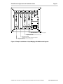
1
SmartPanel Configuration and Installation Guide
Page i
TABLE OF CONTENTS
PART I - INTRODUCTION
OVERVIEW.............................................................................................................................................1
A FIRST LOOK AT THE SMARTPANEL .......................................................................................................2
TWO FORM FACTORS TO FIT EVERY INSTALLATION ..................................................................................3
Full-Size SmartPanel .......................................................................................................................3
Mini “Control-Only” SmartPanel.......................................................................................................3
BEFORE INSTALLING THE SMARTPANEL...................................................................................................4
Using the Configuration Utility .........................................................................................................4
Outline of this Document .................................................................................................................4
PARTS LIST ...........................................................................................................................................5
INSTALLING THE CONFIGURATION SOFTWARE.............................................................................6
RUNNING THE INSTALLATION PROGRAM ..................................................................................................6
CONNECTING THE PANEL TO YOUR COMPUTER........................................................................................6
SPECIFYING A COM PORT .......................................................................................................................7
USING THE CONFIGURATION UTILITY .......................................................................................................8
CHANGES MUST BE DOWNLOADED ..........................................................................................................9
The status bar ..................................................................................................................................9
Panel settings are retrieved by the Configuration Utility..................................................................9
How to download settings..............................................................................................................10
DOWNLOAD-ONLY MODE .....................................................................................................................10
Manually placing the Panel in download-only mode .....................................................................11
Restoring normal operation after using download-only mode.......................................................11
PART II - CONFIGURING AND USING THE PANEL
PROJECTOR DRIVERS.......................................................................................................................13
SELECTING A PROJECTOR DRIVER ........................................................................................................13
PROJECTOR DRIVER APPLICATION NOTES ............................................................................................14
PROJECTOR DRIVERS AND APPLICATION NOTES ON THE WEBSITE .........................................................15
INPUT SOURCE SELECTION AND INPUT MAPPING ......................................................................16
USING THE PANEL TO SELECT INPUT SOURCES .....................................................................................16
What input source selection does from the installer’s perspective................................................17
MAPPING PROJECTOR INPUTS ..............................................................................................................17
Why inputs must be mapped .........................................................................................................17
How to map inputs .........................................................................................................................17
A note on using relays to control an external switcher ..................................................................18
COORDINATING INPUT MAPPING WITH MODULES AND LEGENDS .............................................................19
Module Placement for the Large Chassis......................................................................................19
Auxiliary Patch Point Placement for the Small Chassis ................................................................20
Making it All Work Together...........................................................................................................20
HIDDEN FUNCTIONS ..........................................................................................................................22
WHY FUNCTIONS ARE HIDDEN ...............................................................................................................22
MAPPING HIDDEN FUNCTIONS ..............................................................................................................23
Mapping No Hidden Function ........................................................................................................24
© 2002-8 SP Controls, Inc. 930 Linden Avenue South San Francisco CA 94080
www.spcontrols.com
Page ii
SmartPanel Configuration and Installation Guide
PANEL AND PROJECTOR POWER .................................................................................................. 25
POWER CONTROLS AND INDICATION ..................................................................................................... 25
POWER STATES .................................................................................................................................. 25
Projector power is more complex than on and off......................................................................... 25
Projector Power States.................................................................................................................. 25
Panel vs. Projector Power ............................................................................................................. 26
POWER STATUS INDICATORS ............................................................................................................... 26
THE WARM-UP TIMER ......................................................................................................................... 27
THE LOCKOUT TIMER ........................................................................................................................... 27
How the Lockout Timer affects users............................................................................................ 27
THE INACTIVITY SHUTDOWN TIMER ....................................................................................................... 28
Configuring the Inactivity Shutdown Timer.................................................................................... 29
How the Inactivity Shutdown Timer affects users ......................................................................... 29
PROJECTOR POWER STATUS FEEDBACK .................................................................................... 31
How Power Status Feedback affects users .................................................................................. 31
USING RS-232 POWER POLLING ......................................................................................................... 32
USING A POWER CURRENT SENSOR ..................................................................................................... 32
DOING WITHOUT POWER FEEDBACK ...................................................................................................... 32
VOLUME .............................................................................................................................................. 34
VOLUME CONTROLS AND INDICATION .................................................................................................... 34
Relative vs. absolute volume modes............................................................................................. 34
USING THE PROJECTOR’S SPEAKERS ................................................................................................... 35
USING THE AUDIO FOLLOW VIDEO PREAMPLIFIER ................................................................................. 35
When you need the Preamplifier................................................................................................... 36
What the Audio Follow Video Preamplifier does for you............................................................... 37
A functional description of the Audio Follow Video Preamplifier................................................... 37
CONFIGURING THE AUDIO FOLLOW VIDEO PREAMPLIFIER ...................................................................... 38
EQUALIZATION ..................................................................................................................................... 39
Defeating equalization................................................................................................................... 39
GAIN ................................................................................................................................................... 40
Defeating Gain (converting the Preamplifier into a switcher)........................................................ 41
VIDEO SWITCHING WITH THE AUDIO FOLLOW VIDEO PREAMPLIFIER........................................................ 41
CONTROL WIRING OPTIONS ............................................................................................................ 42
DECIDING BETWEEN WIRED REMOTE AND THE IR EMITTER.................................................................... 42
Using wired remote ....................................................................................................................... 42
Using the included IR Emitter........................................................................................................ 42
WHEN THE PANEL USES RS-232 AND WIRED REMOTE/IR ..................................................................... 43
Why the Panel uses both RS-232 and Wired Remote/IR ............................................................. 43
RELAYS ............................................................................................................................................... 44
POWER RELAYS .................................................................................................................................. 44
SELECTION RELAYS ............................................................................................................................. 47
MODULES AND LEGENDS ................................................................................................................ 49
LEGENDS ............................................................................................................................................ 49
SELECTING AND ARRANGING MODULES OR AUXILIARY PATCH POINTS ................................................... 49
AUXILIARY PATCH POINTS .............................................................................................................. 51
www.spcontrols.com
© 2002-8 SP Controls, Inc. 930 Linden Ave. So. San Francisco CA 94080
SmartPanel Configuration and Installation Guide
Page iii
PART III - ASSEMBLY AND INSTALLATION
SMARTPANEL ASSEMBLY ................................................................................................................53
INSERTING LEGENDS ............................................................................................................................53
INSERTING THE MODULES ....................................................................................................................54
ATTACHING THE AUDIO FOLLOW VIDEO PREAMPLIFIER (OPTIONAL) ........................................................55
SMARTPANEL INSTALLATION..........................................................................................................56
INSTALLING THE TERMINAL BLOCKS ......................................................................................................56
WIRING PANEL POWER ........................................................................................................................57
WIRING THE RELAYS ............................................................................................................................58
WIRING PROJECTOR CONTROL .............................................................................................................59
RS-232...........................................................................................................................................59
Wired Remote/IR ...........................................................................................................................59
Current Sensor (optional) ..............................................................................................................59
WIRING AUDIO TO THE AUDIO FOLLOW VIDEO PREAMPLIFIER (OPTIONAL) ..............................................60
INSTALLING THE SMARTPANEL IN A BACKBOX ........................................................................................61
PART IV - SUPPORTING DOCUMENTATION
TROUBLESHOOTING GUIDE .............................................................................................................62
SPECIFICATIONS ................................................................................................................................70
CONTACTING SP CONTROLS ...........................................................................................................71
WWW.SPCONTROLS.COM ......................................................................................................................71
CUSTOMER SUPPORT ...........................................................................................................................71
MAILING ADDRESS ...............................................................................................................................71
WARRANTY .........................................................................................................................................72
COPYRIGHT INFORMATION ..............................................................................................................72
© 2002-8 SP Controls, Inc. 930 Linden Avenue South San Francisco CA 94080
www.spcontrols.com
Page iv
SmartPanel Configuration and Installation Guide
INDEX OF TABLES, FIGURES AND EXAMPLES
TABLE 1: PARTS LIST ................................................................................................................................ 5
TABLE 2: PROJECTOR POWER STATES ..................................................................................................... 26
FIGURE 1: FULL-SIZE SMARTPANEL WITH MODULES INSTALLED ................................................................... 2
FIGURE 2: THE MINI SMARTPANEL............................................................................................................. 2
FIGURE 3: CONNECTING THE SMARTPANEL TO YOUR COMPUTER................................................................. 7
FIGURE 4: SELECTING THE COM PORT ....................................................................................................... 7
FIGURE 5: THE CONFIGURATION UTILITY .................................................................................................... 8
FIGURE 6: PROJECTOR DRIVER SELECTION DIALOG .................................................................................. 13
FIGURE 7: DRIVERS ON THE SP CONTROLS, INC. WEBSITE. ...................................................................... 16
FIGURE 8: INPUT MAPPING AND CHANGING THE PROJECTOR DRIVER ......................................................... 16
FIGURE 9: EXAMPLE COORDINATION OF INPUT MAPPING WITH MODULES AND LEGENDS ............................. 21
FIGURE 10: HIDDEN FUNCTIONS .............................................................................................................. 23
FIGURE 11: POWER CONTROLS AND INDICATION ....................................................................................... 25
FIGURE 12: THE LOCKOUT AND INACTIVITY SHUTDOWN TIMERS ................................................................ 28
FIGURE 13: POWER STATUS FEEDBACK AND CONTROL WIRING ................................................................. 31
FIGURE 14: VOLUME CONTROL AND INDICATION ........................................................................................ 34
FIGURE 15: THE SP3-AFVP+ AUDIO FOLLOW VIDEO PREAMPLIFIER. ....................................................... 35
FIGURE 16: FUNCTIONAL BLOCK DIAGRAM OF THE SP3-AFVP+ AUDIO FOLLOW VIDEO PREAMPLIFIER ....... 36
FIGURE 17: CONFIGURING THE AUDIO FOLLOW VIDEO PREAMPLIFIER ....................................................... 38
FIGURE 18: POWER RELAYS .................................................................................................................... 44
FIGURE 19: CONFIGURING RELAYS .......................................................................................................... 46
FIGURE 20: SELECTION RELAYS ............................................................................................................... 47
FIGURE 21: SOME OF THE MODULES AVAILABLE ....................................................................................... 50
FIGURE 22: AUXILIARY PATCH POINTS ON A FULL-SIZE PANEL ................................................................... 51
FIGURE 23: INSERTING LEGENDS ............................................................................................................. 53
FIGURE 24: ATTACHING THE MODULES. ................................................................................................... 54
FIGURE 25: ATTACHING THE AUDIO FOLLOW VIDEO PREAMPLIFIER ........................................................... 55
FIGURE 26: INSTALLING THE PHOENIX CONNECTOR TERMINAL BLOCKS ....................................................... 56
FIGURE 27: WIRING PANEL POWER .......................................................................................................... 57
FIGURE 28: WIRING RELAYS .................................................................................................................... 58
FIGURE 29: WIRING PROJECTOR CONTROL ............................................................................................... 59
FIGURE 30: WIRING RCA AUDIO TO THE PREAMPLIFIER ............................................................................ 60
FIGURE 31: WIRING 1/8” AUDIO TO THE PREAMPLIFIER ............................................................................. 60
FIGURE 32: INSTALLING THE SMARTPANEL IN A BACKBOX ......................................................................... 61
EXAMPLE 1: SELECTING A PROJECTOR DRIVER ........................................................................................ 14
EXAMPLE 2: MAPPING INPUTS ................................................................................................................. 19
EXAMPLE 3: MAPPING HIDDEN FUNCTIONS .............................................................................................. 24
EXAMPLE 4: CONFIGURING THE LOCKOUT TIMER ...................................................................................... 28
EXAMPLE 5: CONFIGURING THE INACTIVITY SHUTDOWN TIMER .................................................................. 30
EXAMPLE 6: ADJUSTING EQUALIZATION SETTINGS .................................................................................... 40
EXAMPLE 7: ADJUSTING GAIN SETTINGS .................................................................................................. 41
EXAMPLE 8: USING A POWER RELAY FOR SCREEN CONTROL .................................................................... 45
EXAMPLE 9: USING THE SELECTION RELAYS WITH AN EXTERNAL SWITCHER .............................................. 48
www.spcontrols.com
© 2002-8 SP Controls, Inc. 930 Linden Ave. So. San Francisco CA 94080
SmartPanel Configuration and Installation Guide
Page 1
PART I - INTRODUCTION
Overview
Welcome to the world of the SmartPanel, the perfect control system for small projector
installations.
The SmartPanel is the right choice for permanent single projector installations because it is costeffective and easy to configure.
The Panel provides users with a simple, reliable way to control a projector.
x Unlike a remote control, the Panel is never lost, pointed the wrong way, or in need of
batteries. The Panel replaces cryptic feature names and menus of rarely used functions
with simple, point-of-connection controls.
x Users are always provided with feedback about the status of the projector.
x The control system behavior is simple and uniform, regardless of projector model. Once
familiar with the Panel, users can control different projector models at the same site with no
additional training.
The Panel provides installers with a pre-programmed and easily configured solution to simple
control tasks.
x Modules provide high quality patch points for common projector sources.
x The Panel’s modular design and two form factors allows it to be custom tailored for every
installation.
x Configurable relays are provided to control common external devices such as switchers
and powered screens.
x No programming is necessary, only configuration with an easy-to-use Windows™ utility. All
the software needed to configure the Panel is included, and updates and additional utilities
are provided on the SP Controls website.
This guide gives you everything you need to successfully install and configure the SmartPanel.
All we assume is that you are familiar with the projector you’ve chosen, and that you have done
small projector installations before.
From all of us at SP Controls, thanks for your interest and business. We hope that the
SmartPanel makes your job easier by simplifying installations, while satisfying your end users on
all fronts – cost, ease of use, and reliability.
Note: The SmartPanel is not a switcher; it is strictly a control system. Your design should rely on
switching built into your projector or external switchers.
© 2002-8 SP Controls, Inc. 930 Linden Avenue South San Francisco CA 94080
www.spcontrols.com
Page 2
SmartPanel Configuration and Installation Guide
A First Look at the SmartPanel
Selection Buttons
Selection buttons are removable
if you have less than four inputs
Power Control
IR Learning Window
(for future use)
Backlit Legends
Legends indicate current
selection with installerchosen labels
Volume Control
Projector
Volume
ON
COMPUTER 1
DOCUMENT
CAMERA
COMPUTER 2
AUXILIARY
VIDEO
Ready
Warm-up
OFF
Auxiliary Patch Points
R
VGA
Macintosh
Video
H
G
V
B
Audio
Patch Modules
(example configuration shown)
Audio
Audio
Audio
L
R
L
R
L
R
L
R
6
6
6
6
6
6
6
6
Lucent Tech. M100
series Escutcheon
Figure 1: Full-size SmartPanel (SP2-CHAS) with Modules installed
Selection Buttons
Selection buttons are removable if
you have less than four inputs
Backlit Legends
Legends indicate current selection with
installer-chosen labels
Power Control
IR Learning Window
(for future use)
Volume
Control
Projector
COMPUTER 1
DOCUMENT
CAMERA
Volume
ON
COMPUTER 2
Ready
AUXILIARY VIDEO
Warm-up
OFF
Figure 2: The Mini SmartPanel (SP2-SMCHAS)
The assembled SmartPanels shown in Figure 1 and Figure 2 demonstrate the following
features:
x Four selection buttons control projector input switching.
x Power buttons control projector power. The user is given feedback of the projector’s
status by a pair of LEDs. The Panel uses RS-232 or current sensors to remain in sync with
projectors.
x Volume buttons control volume, which is indicated on an LED bar graph. An optional
Audio Follow Video Preamplifier is available for use with external audio solutions, such
as self-powered speakers.
x Back-lit Legends are readable in any light. Legends appropriate for each installation are
chosen and inserted by the installer. Custom Legends can be prepared.
www.spcontrols.com
© 2002-8 SP Controls, Inc. 930 Linden Ave. So. San Francisco CA 94080
SmartPanel Configuration and Installation Guide
Page 3
Our goal was elegant and straightforward design. We hope that we succeeded and that you find
the Panel intuitive to use.
Two Form Factors to Fit Every Installation
The SmartPanel comes in two form factors to fit every installation and budget.
Full-Size SmartPanel
The assembled SmartPanel in Figure 1 is configurable with four Modules and three Auxiliary
Modules. The Modules provide point-of-control connection for portable projector sources, such
as laptops, so users can patch in and control the system at the same location.
Modules are chosen, ordered and attached by the installer. Selection-only Modules (with no
patch points) are available for permanently installed devices, and blanks are available for
installations that have fewer than four input devices.
Note: Facing the front of the Panel, the leftmost Module is “input one,” and the rightmost “input
four”.
Mini “Control-Only” SmartPanel
The Mini SmartPanel is an elegant, small-footprint alternative for installations where space or
aesthetics are at a premium. The Mini SmartPanel provides the same comprehensive control
over projectors as the full-size Panel, without integrated patch points. Auxiliary Patch Points can
be integrated when the Panel is mounted in a drawer (SBL-1050B) or rack (SP2-RACKSMMOD).
The Mini SmartPanel is available in several finishes to match any décor.
Note: Unless otherwise noted, instructions and directions apply to both form factors. The full-size
SmartPanel and control-only SmartPanel are identical from a configuration and wiring
perspective. Only the facia differs.
© 2002-8 SP Controls, Inc. 930 Linden Avenue South San Francisco CA 94080
www.spcontrols.com
Page 4
SmartPanel Configuration and Installation Guide
Before Installing the SmartPanel
Before you assemble, configure and install the SmartPanel, review this documentation. Informed
configuration decisions make your installation go smoothly and ensure that the Panel is easy for
clients to use.
Using the Configuration Utility
The SmartPanel is configured using the included Configuration Utility (for Windows™). The
Utility lets you tailor the Panel’s control of your projector for your installation.
Outline of this Document
Part I - Introduction continues with a review of the packing list of the Panel and a guide to
installing and using the Configuration Utility.
Part II - Configuring and Using the Panel discusses the features of the Panel. Controls and
features are defined. Examples demonstrate common configuration changes with the
Configuration Utility.
Assembly and wiring of the Panel are described in Part III - Assembly and Installation.
Part IV - Supporting Documentation provides a troubleshooting guide and standard disclaimers
and contact information.
www.spcontrols.com
© 2002-8 SP Controls, Inc. 930 Linden Ave. So. San Francisco CA 94080
SmartPanel Configuration and Installation Guide
Page 5
PARTS LIST
Before reading further, you should review the following packing list to familiarize yourself with the
SmartPanel and its component parts. Verify that the complete Panel package and any optional
accessories you ordered were shipped.
SmartPanel
Chassis
Power supply
Legends
IR emitter
8 Self-tapping 6-32
screws
Configuration and
Installation Guide
SmartPanel
Configuration
Utility
The control unit and Module frame itself. Includes one projector control RS-232
port, one RS-232 configuration port, one Wired Remote/Infrared port, one
power sensor input, and seven low voltage relays.
12V 600mA DC regulated
Pre-printed Legends to be inserted beneath each Module, each describing an
input (e.g., COMPUTER 1, DOCUMENT CAMERA, etc.). Blanks are included.
The matching font is TrueType™ Impact.
Dual blink type emitter to be affixed to the projector’s IR window. The emitter
glows red while emitting IR to aid troubleshooting.
Note: When the Panel is configured for Wired Remote, the emitter is not used.
For mounting the SmartPanel into a backbox (not included). Only four screws
are needed but extras are provided.
This document.
CD-ROM containing Windows™ Configuration Utility software and a suite of
Drivers for popular projector models. The Utility allows you to configure how
the Panel controls the projector.
Note: To use this software you need an RS-232 cable (standard male 9-pin to
female). This cable is not included.
OPTIONAL COMPONENTS – included only if ordered.
The exact Modules accompanying your Panel are specified at the time of
Modules (4)
order. Arrangement on the chassis is determined by the installer at the
time of assembly.
(SP2-CHAS)
Note: Modules are only needed with the full-size SmartPanel.
Accessory provides switching and preamplification for all Panel inputs. A
Audio Follow Video
video switching section provides additional video inputs for installations
Preamplifier
requiring more video inputs than the projector supplies. The Preamplifier
can be configured to set gain and/or bass and treble equalization for each
channel.
Rack mount kit
Auxiliary Patch Points
(SP2-SMCHAS with
SP2-RACKSM-MOD or
SLB-1050B)
Note: The Preamplifier is not needed if the projector’s internal speakers
and internal volume control are used.
Accessory kits allow the Panel to be mounted in a standard 19” rack. The
SP2-CHAS rack mount occupies five rack units. The SP2-SMCHAS rack
mount occupies two rack units.
The exact Auxiliary Patch Points accompanying your Panel are specified
at the time of order. Arrangement on the chassis is determined by the
installer at the time of assembly.
Note: Auxiliary Patch Points are needed with the control-only SmartPanel
only when it is mounted in Modular Rack Mount (SP2-RACKSM-MOD) or
Slide Out Drawer (SLB-1050B).
Table 1: Parts list
© 2002-8 SP Controls, Inc. 930 Linden Avenue South San Francisco CA 94080
www.spcontrols.com
Page 6
SmartPanel Configuration and Installation Guide
INSTALLING THE CONFIGURATION SOFTWARE
After unpacking the SmartPanel, you should install the included Configuration Utility software
and verify that you can communicate with the Panel.
The Configuration Utility requires Windows 95™ or later. Make sure you have an 9-pin male to
9-pin female RS-232 cable (wired straight through), which is not included. This cable connects
your computer to the Panel’s Configuration Port (upper left, Panel rear).
Running the Installation Program
To install the Configuration Utility software, insert the Utility CD-ROM into your floppy drive and
run the Setup program found on that disk. This program installs the Utility on your computer. By
default, the Utility and its accompanying files (e.g., projector drivers and their application note)
are placed in the
\Program Files\SPC\
directory on your main hard disk (usually C:). A shortcut to the Utility is placed in your Windows
Start button menu as Start: Programs: SmartPanel Utilities: SmartPanel Configuration
Utility.
Connecting the Panel to your Computer
To configure the Panel, you must supply it with power and connect it to your PC (a laptop is
convenient), as shown in Figure 3.
Power should be supplied to the Panel with the included 12VDC regulated power supply. When
powered, all of the lights on the Panel rapidly flash in sequence as it runs through a power-on
self-test. If this self-test does not occur, make sure you have correctly powered the unit (see
Wiring Panel Power or the Troubleshooting Guide if necessary).
Connect the Panel to your computer by attaching the male 9-pin end of your RS-232 cable (not
included) to the Panel’s Configuration Port. Attach the female end of the cable to any free Com
Port on your computer.
Note: It is your responsibility to make sure that the Com Port you are using is enabled and
configured correctly. You don’t need to worry about communications settings (e.g., baud
rate), but you do need to make sure that the communication port you wish to connect
through has not been disabled at the hardware level (if you have used the Com Port before
for other applications, you should have no problems).
Note: It is not necessary to disconnect the Panel from the projector to run the Configuration
Utility.
www.spcontrols.com
© 2002-8 SP Controls, Inc. 930 Linden Ave. So. San Francisco CA 94080
SmartPanel Configuration and Installation Guide
GND
+12V DC
1
7B
7A
6B
6A
5B
5A
3A
POWER
500mA MAX. CURRENT
SELECTION
(EXT. SWITCHER CTRL)
3
2
4B
2A
4
4A
PWR
OFF
MOM.
3B
PWR
ON
MOM.
2B
PWR
ON
MAINT.
1B
12VDC Regulated Power Supply
included
CAUTION
"INDOOR USE
ONLY"
SENSE
IR/SER
GND
+12V
CTS
RTS
RS-232 Cable
(DB9 Male to Female - straight through)
not included
To Com Port
on PC
RELAYS
IR/SERIAL
GND
TX
ACCESSORY
BUS
RX
AUDIO FOLLOW VIDEO
SWITCHER EXPANSION
RS232
1A
PROJECTOR CONTROL
CONFIGURATION
PORT
Page 7
Figure 3: Connecting the SmartPanel to your computer
Specifying a Com Port
Before configuring the SmartPanel you must specify the Com Port
you are using to connect to it.
When you run the Configuration Utility for the first time the dialog
shown in Figure 4 will appear. Select the Com Port you are using and
press OK.
Note: The dialog does not allow you to select a Com Port that is
disabled or being used by another program.
The Utility remembers the port selected and uses it in subsequent
sessions. If you later attach to the Panel through a different port,
change the active port with the Configuration Utility’s
Communications pulldown.
Figure 4: Selecting
the Com Port
After a Com Port is selected, the Utility should appear as shown in
Figure 5.
© 2002-8 SP Controls, Inc. 930 Linden Avenue South San Francisco CA 94080
www.spcontrols.com
Page 8
SmartPanel Configuration and Installation Guide
Tabs switch between sets of settings
Changes Projector
Drivers to support
your projector
Name of loaded
Projector Driver
Input mapping section
Downloads settings
changes to the Panel
Download
progress indicator
Status of Panel connection
Panel firmware revision
information
Active Com port
Figure 5: The Configuration Utility
Using the Configuration Utility
The Configuration Utility configures your SmartPanel to work with your projector and lets you
tailor its behavior for your installation. Panel configuration consists of:
x selecting a Projector Driver,
x setting configuration options, and
x downloading changes to the Panel.
www.spcontrols.com
© 2002-8 SP Controls, Inc. 930 Linden Ave. So. San Francisco CA 94080
SmartPanel Configuration and Installation Guide
Page 9
Changes must be downloaded
Changes made with the Utility are not sent to the Panel until you hit the Download Settings
button. Do not expect to see any changes in Panel behavior until changed settings are
downloaded to the Panel.
The status bar
The status bar at the bottom of the Utility window provides feedback on the current state of the
Utility (and Panel, if it is connected and detected).
The first field, farthest to the left, identifies which Com Port the Utility is using to connect to the
Panel.
The second field from the left indicates the Panel’s connection status, as follows:
x Panel Present indicates that the RS-232 cable is correctly connected to the Panel.
x Connected indicates that the RS-232 cable is connected to a device, but that it does not
appear to be a SmartPanel (this can happen if the Panel is connected but not powered).
x Not Connected indicates that the RS-232 cable does not appear to be connected to any
device.
Note: When the Configuration Utility does not detect any Panel on the active Com Port the
Download Settings button is disabled.
The rightmost field provides feedback on any download in progress. The remaining fields display
version information about the attached Panel. These fields are discussed in the sections that
follow.
Panel settings are retrieved by the Configuration Utility
The Utility retrieves the current settings of any Panel connected to the computer.
When the connected Panel’s current settings are retrieved, the third and fourth fields in the status
bar display the firmware and memory format revision numbers of the Panel for customer support
use.
After Panel settings are retrieved, the Utility opens the Projector Driver file last downloaded to
the Panel. If this Driver is not in the directory into which the Utility was installed, a dialog labeled
Open Proj File will appear and prompt you to find the Driver (.prj) file.
If you know where this file is, identify it. If it is not available (for example, because the Panel was
originally configured with a different computer), press Cancel.
Once Panel settings are retrieved you can examine and modify them as described in Part II Configuring and Using the Panel.
Note: Do not change configuration settings when no Panel is connected, or before Panel settings
are retrieved. Changes made before connecting the Panel (or before the Panel is
recognized by the Utility) will be overwritten if existing settings are retrieved.
© 2002-8 SP Controls, Inc. 930 Linden Avenue South San Francisco CA 94080
www.spcontrols.com
Page 10
SmartPanel Configuration and Installation Guide
How to download settings
Configuration changes are saved to the Panel with the Download Settings button, found in the
lower right corner of the Configuration Utility. Downloading is only possible after the Panel is
correctly connected and its existing settings have been retrieved.
While downloading the cursor becomes an hourglass, and a bar graph indicator (at the lower
right of the Utility) flushes to indicate progress. Downloading should take no more than thirty
seconds.
After a successful download, the Panel resets itself. Changes are effective as soon as a
download finishes and the Panel resets. If for some reason the Panel does not reset, you should
download again.
Occasionally, communications may fail during downloading. If any errors occur during download,
try downloading again. If you are unable to successfully download, make sure the Panel has
been detected.
If you never successfully download, put the Panel in download-only mode as described below.
Note: Future revisions of the Configuration Utility software will allow users to save copies of
Panel configuration settings on the PC, but this is not supported in the initial release. Check
the SP Controls website for new versions.
Note: The AFVP tab of the Utility is active only when an Audio Follow Video Preamplifier is
connected to the Panel. The Panel automatically detects whether a Preamplifier is present.
Download-Only Mode
The SmartPanel has a download-only mode to ensure it can always be configured or updated.
In this mode, the Panel does not communicate with the projector1. The only communication
allowed while the Panel is in download-only mode is the downloading of configuration or driver
changes.
Download-only mode allows reconfiguration of the Panel should configuration memory become
corrupted. Reconfiguration is essential in these cases, as corrupt memory disrupts control of the
projector and may in rare cases cause serious Panel behavior problems such as “freezing.”
When in download-only mode the Panel the red Warm-Up indicator LED blinks continuously
while the Panel is on2.
The Panel automatically places itself in download-only mode if it detects any of a variety of
special conditions, such as corrupted configuration memory, or firmware compatibility problems.
1
RS-232 power polling is suspended while the Panel is in download only mode.
Blinking of the Warm-Up indicator when the Panel is off indicates that the projector is cooling;
see The Lockout Timer.
2
www.spcontrols.com
© 2002-8 SP Controls, Inc. 930 Linden Ave. So. San Francisco CA 94080
SmartPanel Configuration and Installation Guide
Page 11
Manually placing the Panel in download-only mode
The Panel is manually placed in download-only mode by pressing and holding the On, Off and
Selection Four buttons while applying power. This combination of keys was chosen because it is
unlikely to occur by accident.
Manual activation of download-only mode facilitates reconfiguration should serious corruption of
configuration memory occur.
Restoring normal operation after using download-only mode
Download-only mode is exited by removing and restoring power to the Panel.
If download-only mode was entered automatically because a problem was detected by Panel
firmware self checks, that problem must be remedied before the Panel will function normally. In
most cases, re-downloading the appropriate Driver and configuration restores normal operation.
If the Panel is unable to complete a download session in download-only mode, or persists in
automatically entering the mode whenever powered on, it may have developed hardware
problems and require service.
© 2002-8 SP Controls, Inc. 930 Linden Avenue South San Francisco CA 94080
www.spcontrols.com
Page 12
www.spcontrols.com
SmartPanel Configuration and Installation Guide
© 2002-8 SP Controls, Inc. 930 Linden Ave. So. San Francisco CA 94080
SmartPanel Configuration and Installation Guide
Page 13
PART II - CONFIGURING AND USING THE PANEL
PROJECTOR DRIVERS
Selecting a Projector Driver
Projector Drivers contain information on the behavior, control requirements, and features of
each projector the SmartPanel can control. The Panel uses Drivers to control different projectors
and other display devices.
Drivers are distributed as .prj files. Drivers for several popular projectors are installed with the
Configuration Utility during setup. New and updated Drivers are available at the SP Controls
website (see Contacting SP Controls). The Panel is configured with a Driver at the factory3.
Note: We assume you verified that a Driver was available for your projector before designing for
and purchasing a SmartPanel. However, new Drivers do become available as projectors
enter the market.
To configure the Panel to work with your projector, change Drivers as follows:
x Connect your PC to the Panel and install the Configuration Utility as described above.
x Run the Utility and wait for the Panel to be detected and its settings retrieved.
x Press the Change Projector Driver button in Projector Selection (as shown in Figure 8).
An Open Proj File dialog will appear as shown in Figure 6.
Figure 6: Projector Driver selection dialog
3
When this manual was written, the Panel was shipped configured for the Sharp XG-E3000U.
© 2002-8 SP Controls, Inc. 930 Linden Avenue South San Francisco CA 94080
www.spcontrols.com
Page 14
SmartPanel Configuration and Installation Guide
The dialog opens on the directory into which the Utility was installed (by default, \Program
Files\SPC\). This directory is where Drivers are installed during Utility setup. When you
download new drivers from the website, you should place them in this directory.
Select a Driver from the list and press Open. The new Driver is loaded into the Utility, which
should then display the Driver’s default settings. The new Driver and settings are not sent to the
Panel until you download.
Press Cancel if you decide not to load a Driver. Current settings will remain unchanged.
Note: Changing the Projector Driver does not affect settings for relays or the Audio Follow
Video Preamplifier.
Example 1: Selecting a Projector Driver
In this example, you configure your Panel with the Sharp XG-E1200U Driver.
To configure the Panel in this manner:
x connect the Panel to your computer and run the Configuration Utility;
x wait for current Panel settings to be retrieved;
x make sure the Projector Selection tab is showing;
x click the Change Projector Driver button;
x in the dialog that appears, select the Driver named Sharp XG-E1200U, as shown in
Figure 64;
x press the Open button;
x wait for the Driver file to load into the Utility, as shown in Figure 8;
x optionally, adjust configuration settings as necessary;
x download the new settings by clicking Download Settings.
The Panel will now send control commands and use timers appropriate to the Sharp
XG-E1200U.
Projector Driver Application Notes
Every Projector Driver has a Projector Driver Application Note. This document describes:
x the default configuration settings specified by the Driver,
x requirements for wiring to and controlling the projector (e.g., RS-232 cable pinouts), and
x any known problems with the projector, or side effects of using specific features.
Always read the Application Note for tips and advice on using the Panel with the supported
projector. We put our time into the Application Notes so you don’t waste yours learning every
detail of every projector.
Note: When you select a Driver and open it, the Driver’s default configuration is loaded, even if
the Panel is already configured for that Driver. This allows you to restore a Driver’s default
settings.
4
The Drivers listed in the dialog vary depending on which Drivers you have installed.
www.spcontrols.com
© 2002-8 SP Controls, Inc. 930 Linden Ave. So. San Francisco CA 94080
SmartPanel Configuration and Installation Guide
Page 15
Projector Drivers and Application Notes on the Website
SP Controls, Inc. is continually creating and updating Drivers. New projector models are
released, the Panel is installed to control legacy projectors, and existing Drivers are improved as
we receive feedback from installations in the field.
To get the latest Drivers and their Application Notes, visit the SP Controls, Inc. website at:
http://www.spcontrols.com
At the site, visit the Downloads and Support section, and select Projector Drivers. Instructions for
downloading and installing Drivers and Application Notes are available on the site itself.
You can also download the Configuration Utility, this Guide, and other useful documents.
Note: Always check the website for new and updated Drivers before doing an installation!
© 2002-8 SP Controls, Inc. 930 Linden Avenue South San Francisco CA 94080
www.spcontrols.com
Page 16
SmartPanel Configuration and Installation Guide
Figure 7: The latest Drivers are always available on the SP Controls, Inc. website
INPUT SOURCE SELECTION AND INPUT MAPPING
Change Projector Driver
Loads Drivers to control
different projectors
Input Mapping Section
Configures commands sent
to the projector when
selection buttons are
pressed
Figure 8: Input Mapping and changing the Projector Driver
Using the Panel to Select Input Sources
The SmartPanel makes changing the projected input source easy and intuitive.
To change the projector source, press one of the Panel’s four selection buttons.
Note: The SmartPanel is not a switcher; it is a control system. The Panel controls input source
selection by directing the projector to switch between the projector’s inputs, or by
controlling external switchers with its selection relays.
www.spcontrols.com
© 2002-8 SP Controls, Inc. 930 Linden Ave. So. San Francisco CA 94080
SmartPanel Configuration and Installation Guide
Page 17
What input source selection does from the installer’s perspective
The projector (and any external switcher) is controlled with the four selection buttons.
When a selection button is pressed, the Panel:
x sends a command to the projector, telling it to switch inputs;
x opens and closes selection relays on the Panel to control third-party switchers5; and
x brightens the appropriate Legend to show the new selection.
This section explains how these behaviors are configured.
Mapping Projector Inputs
Input mapping is the process of configuring the Panel to send the projector particular input
source selection commands when selection buttons are pressed.
For a discussion of coordinating input mapping with selection relays controlling external
switchers, see the end of this section (a complete treatment is found in Selection Relays).
Why inputs must be mapped
The command sent when a selection button is pushed must be configured because there is no
fixed relationship between the Panel’s selection buttons and the projector’s inputs.
We could have made selection button one always switch the projector Video, and selection
button two correspond to RGB, but this was a bad idea.
This is true because:
x different projectors have different numbers and different types of inputs, not to mention
different conventions on how sources are labeled and selected;
x the large SmartPanel Modules are designed to be arranged in any order, while the
selection buttons occupy fixed locations on the Panel;
x every installation has different input source devices to switch between; and
x several selectable sources may use the same input at the projector, and be switched by a
third-party switcher.
How to map inputs
The Configuration Utility allows you to specify which of a projector’s inputs is switched to when
each selection button is pressed.
As shown in Figure 6, each selection button is graphically associated with a projector input. The
input associated with, or mapped to, a particular selection button is shown in the box called out
for that button. The input displayed for each selection button is the one the projector is instructed
to switch to when that button is pressed.
5
The Audio Follow Video Preamplifier provides is configurable to provide 4x1 composite video or
2x1 S-Video switching . See Video Switching with the Audio Follow Video Preamplifier.
© 2002-8 SP Controls, Inc. 930 Linden Avenue South San Francisco CA 94080
www.spcontrols.com
Page 18
SmartPanel Configuration and Installation Guide
To change a button’s input mapping, click the input box associated with it. A list of the projector’s
built-in inputs appears in the form of a pulldown list box. Inputs vary by projector model; for a list
of the inputs available on a specific model of projector, see the Projector Driver Application
Note that accompanies the projector’s Driver.
The input list is identical for each of the four buttons. Any button can be mapped to any projector
input.
Note: A button can be mapped to any input regardless of how the other buttons are mapped.
When more than one button is mapped to the same projector input, an external switcher
must be used to switch between source devices; the Panel’s selection relays can control
this switcher.
Note: The Modules shown on the Configuration Utility panel graphic do not change during
input mapping. There is no fixed correspondence between projector inputs and Modules.
A note on using relays to control an external switcher
External switchers are commonly used when multiple input sources are mapped to a single
projector input. We assume you are familiar with using switchers in this fashion.
The SmartPanel can control external switchers (such as those manufactured by Altinex™) with
its configurable, low-voltage selection relays. These relays close according to the active
selection and can be configured for either momentary or maintained closure.
See Selection Relays below for specifics on how to use selection relays to control an external
switcher.
Note: An external switcher may be unnecessary when using the Audio Follow Video
Preamplifier, as it provides 4x1 composite video or 2x1 S-Video switching. See Video
Switching with the Audio Follow Video Preamplifier.
www.spcontrols.com
© 2002-8 SP Controls, Inc. 930 Linden Ave. So. San Francisco CA 94080
SmartPanel Configuration and Installation Guide
Page 19
Example 2: Mapping Inputs
In this example, you configure your Panel input mappings for an installation using a Sharp XGE1200U. You map input one to RGB 1, input three to RGB 2, and inputs two and four to VIDEO
as shown in Figure 8.
Since this installation uses two video sources and the Sharp has only one video input, we’ll
assume you’re using an external switcher or the Audio Follow Video Preamplifier to switch
video before it reaches the projector’s VIDEO in. We also assume that the Panel has been
configured with the Sharp XG-E1200U.prj Driver as shown in Example 1.
To configure the Panel in this manner:
x connect the Panel to your computer and run the Configuration Utility;
x wait for current Panel settings to be retrieved;
x select the Projector Selection tab;
x click in the Input One list box; from the list that appears, select RGB 1;
x click in the Input Two list box; from the list that appears, select VIDEO;
x click in the Input Three list box; from the list that appears, select RGB 2;
x click in the Input Four list box; from the list that appears, select VIDEO;
x download the new settings by clicking Download Settings.
The Panel’s selection buttons one and three will now make the Sharp switch to its RGB 1 and
RBG 2 inputs respectively. Selection buttons two and four will now both make the Sharp switch to
the input wired to VIDEO.
Figure 9 shows how a Panel with inputs mapped in this fashion might be assembled.
Coordinating Input Mapping with Modules and Legends
The following elements must be kept consistent while configuring and assembling your Panel:
x the projector input mapped to each button,
x the Modules installed – their type and order,
x the Legend inserted for each Panel button, and
x the selection relays settings that control any external switcher.
Module Placement for the Large Chassis
We assume that if you are using the full-size SmartPanel (SP2-CHAS), you already have the
Modules for your installation. A discussion of Modules is included in Modules and Legends,
below.
Module arrangement is a decision you and your client make together. We strongly recommend
discussing the arrangement of Modules with your clients – especially those that will actually use
the Panel – before installation.
There is no “default” or “standard” order for Modules, since every installation has different users,
devices, and Modules.
© 2002-8 SP Controls, Inc. 930 Linden Avenue South San Francisco CA 94080
www.spcontrols.com
Page 20
SmartPanel Configuration and Installation Guide
Auxiliary Patch Point Placement for the Small Chassis with Rack Mount Kit or Drawer
We assume that if you are using the control-only SmartPanel (SP2-SMCHAS) with the
SP2-RACKSM-MOD Modular Rack Mount Kit or SLB-1050B Slide Out Drawer, you already have
the Auxiliary Patch Points for your installation. A discussion of Patch Points is included in
Auxiliary Patch Points below.
Auxiliary Patch Point arrangement on a rack mount or drawer is a decision you and your client
make together. We recommend discussing the arrangement of Patch Points with your clients –
especially those that will actually use the Panel – before installation.
There is no standard order for Auxiliary Patch Points, since every installation has different users,
devices, and Patch Points.
Making it All Work Together
The Legends inserted during assembly should identify the source associated with each
permanently installed device (such as “VCR” or “DVD”), and the type of input for any Module
(such “Aux Video” or “Laptop”). See Inserting Legends for instructions on inserting the Legends.
If an external switcher is used, the Panel must be configured to control it. See Relays below for
details on how to configure the Panel to control an external switcher.
Finally, your wiring (e.g., of patch points and permanent source devices to the projector) must be
consistent with your configuration choices.
Be sure to document all the choices you make for your future reference. It’s a good idea to
provide the client with a copy of the Panel’s configuration details, in case someone else updates
or troubleshoots the room in the future.
Note: In our experience, mistakes are minimized if the person who assembles and installs the
Panel also configures it!
www.spcontrols.com
© 2002-8 SP Controls, Inc. 930 Linden Ave. So. San Francisco CA 94080
SmartPanel Configuration and Installation Guide
Projector
Page 21
Volume
ON
COMPUTER 1
VCR
COMPUTER 2
AUXILIARY
VIDEO
Ready
Warm-up
OFF
VGA
Macintosh
Audio
Video
Audio
Audio
L
R
L
R
L
R
6
6
6
6
6
6
INPUT SELECTION #4
mapped to send the VIDEO command to the projector
INPUT SELECTION #3
mapped to send the RGB2 command to the projector
INPUT SELECTION #2
mapped to send the VIDEO command to the projector
INPUT SELECTION #1
mapped to send the RGB1 command to the projector
Figure 9: Example coordination of Input Mapping with Modules and Legends
© 2002-8 SP Controls, Inc. 930 Linden Avenue South San Francisco CA 94080
www.spcontrols.com
Page 22
SmartPanel Configuration and Installation Guide
HIDDEN FUNCTIONS
The SmartPanel can control more than volume, input selection, and power. Up to seven
additional commands can be mapped to the buttons on the Panel. These commands, called
hidden functions, let users access advanced projector features.
Typical hidden functions in today’s installations include on-screen menus, Picture-in-Picture,
digital zoom, image adjustment and lens controls.
Hidden functions are used by pressing and holding down the On button, then pressing another
Panel button. The On button is used as a “shift” key.
Hidden functions are mapped using the Configuration Utility and are provided on a projectorby-projector basis. The Application Note for each Projector Driver lists the functions available for
that projector, and specifies the Driver’s default hidden function configuration.
Hidden functions are one of the most powerful features of the Panel.
Note: When a button is pressed while the On button is held down, it does not perform its normal
function; i.e., pressing [On]-Volume Up does not raise volume, it sends the hidden function
(possibly none) configured for Volume Up.
Why functions are hidden
Power, volume, and input selection are appropriate controls for everyday users.
However, there is occasional need to access advanced projector functions. Installers, for
example, need access to lens controls (to focus and adjust the projector), and power users
sometimes want to use digital zoom, or adjust how the projector syncs to their laptop.
Hidden functions provide for this sort of advanced control without compromising the simplicity of
the Panel’s interface. Remember, one of the main goals of the Panel is to make controlling a
projector simple and easy for the everyday user.
We strive to provide a rich enough set of hidden functions for each projector that remote controls
needn’t be used alongside the Panel.
www.spcontrols.com
© 2002-8 SP Controls, Inc. 930 Linden Ave. So. San Francisco CA 94080
SmartPanel Configuration and Installation Guide
Page 23
Figure 10: Hidden Functions
Mapping Hidden Functions
The configuration process for hidden functions is identical to input selection mapping (see
Mapping Projector Inputs).
As shown in Figure 10, each Panel button except On can be associated with a projector
command on the Hidden Functions tab of the Configuration Utility. The command mapped to
a particular button is shown in the box called out for that button. The command displayed in each
box is the one sent to the projector when the button is pressed while On is held down.
To change a button’s hidden function mapping, click the input box associated it. A list of the
projector’s available hidden functions appears in the form of a pull-down list box. This list is
identical for each button; any button can be mapped to any command regardless of the other
mappings.
Note: It often makes sense to use one set of hidden functions during installation (e.g., which
access projector lens controls such as focus, zoom, and orientation), and another set after
installation for power-users (e.g., on-screen menu functions to let power users adjust scan
rates or horizontal and vertical correction for their laptop).
© 2002-8 SP Controls, Inc. 930 Linden Avenue South San Francisco CA 94080
www.spcontrols.com
Page 24
SmartPanel Configuration and Installation Guide
Note: The hidden functions provided vary from projector to projector. See a projector Driver’s
Application Note for a list of hidden functions available for that projector.
Mapping No Hidden Function
To specify that no hidden function is to be associated with a particular button, click in the button’s
input box and press Backspace. A blank box indicates that no hidden function command is to be
sent.
Note: Removing all the hidden function mappings is useful when you want to ensure users don’t
inadvertently adjust projector settings such as focus and zoom.
Example 3: Mapping Hidden Functions
In this example, you configure your Panel’s hidden functions mapping for an installation using a
Sharp XG-E1200U. You map hidden functions to allow use of the Sharp’s built-in on-screen
menus, as shown in Figure 10.
We assume that the Panel has been configured with the Sharp XG-E1200U.prj Driver as
shown in Example 1.
To configure the Panel in this manner:
x connect the Panel to your computer and run the Configuration Utility;
x wait for current Panel settings to be retrieved;
x select the Hidden Functions tab;
x click in the Volume Up list box; from the list that appears, select ADJ UP;
x click in the Volume Down list box; from the list that appears, select ADJ DOWN;
x click in the Power Off list box; from the list that appears, select MENU;
x click in the Input One list box; from the list that appears, select LENS SELECT;
x click in the Input Two list box; from the list that appears, select ENTER;
x click in the Input Three list box; from the list that appears, select ADJ LEFT;
x click in the Input Four list box; from the list that appears, select ADJ RIGHT;
x download the new settings by clicking Download Settings.
The Panel can now access features normally provided only through the remote control!
While holding On down, press Off. The Sharp’s on-screen menu should appear. While the menu
is visible, the four ADJ functions (On plus the Volume and two leftmost selection buttons) let you
navigate through the menu. ENTER (On plus selection button two) selects menu options.
LENS SELECT (On plus selection button one) allows adjustment of lens effects such as Focus
and Zoom, again with the ADJ functions.
Note: The hidden functions available vary by projector model. We can only provide hidden
functions to access the features built-in to each projector.
www.spcontrols.com
© 2002-8 SP Controls, Inc. 930 Linden Ave. So. San Francisco CA 94080
SmartPanel Configuration and Installation Guide
Page 25
PANEL AND PROJECTOR POWER
On Button
Projector
ON
Ready
Warm-up
OFF
Ready Indicator
(green LED)
Warm-Up Indicator
(red LED)
Off Button
Figure 11: Power controls
and indication
Power Controls and Indication
The Panel’s power buttons are easy to use:
x To turn the projector on, press the On button.
x To turn the projector off, press the Off button.
The Panel powers itself on and off to match projector
power. Projector power is verified using RS-232 polling or
via third party power current sensors.
Power States
Projector power is more complex than on and off
It would be nice if on and off were all there was to projector power. However, contemporary
projectors have power cycling complexities that can confuse users accustomed to the
straightforward behavior of consumer audio-visual devices. The most awkward of these
complexities are projector warm-up time, and the minimum prudent time between bulb-off and
bulb-on cycles.
In our experience, user confusion about power states arises as a result of:
x not knowing the power states a projector can be in,
x not knowing the control possible in each power state, and
x uncertainty as to which power state a projector is actually in.
Additional complications arise because every projector handles power states in a slightly different
way.
The sections that follows explain how the Panel manages projector power states.
Projector Power States
Table 2 lists the power states we have identified, and upon which we based Panel behavior. This
list should clarify our treatment of Panel and projector power in the sections that follow.
Note: Download-only mode is a special Panel mode with no relationship to projector functioning;
it is included for comparison of Panel display. See Download-Only Mode for more
information.
© 2002-8 SP Controls, Inc. 930 Linden Avenue South San Francisco CA 94080
www.spcontrols.com
Page 26
Power
State
Off
Waiting for
strike
Warm-Up
SmartPanel Configuration and Installation Guide
Description
Configurable
Delay?
Delay between
power-on request
and bulb striking.
Delay before the
image reaches full
brightness.
No
No
On
Lockout
Delay after poweroff, before projector
may be turned on
again.
Download
Only
Yes
Panel Display
None.
Warm-Up indicator lit.
Input selection Legends back-lit.
Panel
Buttons
Active
On
None
Warm-Up and Ready indicators lit.
Input selection Legends back-lit.
All
Ready indicator lit.
Input selection Legends back-lit.
None. Warm-Up indicator blinks if
On is queued.
All
Warm-Up indicator blinks while
Panel is powered on.
On6
Off
All7
Table 2: Projector power states
Panel vs. Projector Power
The Panel attempts to remain in sync with the Projector it controls at all times. When the projector
is on, the Panel should be on, and vice versa. Therefore, “Panel power” and “projector power” are
used somewhat interchangeably.
Power Status Indicators
Projector power states are generally communicated to the user with indicators on the projector
itself. However, these indicators (usually LEDs) are invisible to anyone holding a remote twenty
feet away.
To alleviate user confusion about power states, there are two power status indicators on the
SmartPanel that communicate the projector’s power state:
x a red LED acts as a Warm-Up indicator, and
x a green LED acts as Ready indicator.
The Ready indicator comes on when the Panel believes the projector is on and controllable. It
stays on as long as this is believed to be the case.
Note: When the Panel is waiting for the projector bulb to strike the Ready light remains dark and
the projector cannot be controlled. Most projectors do not accept control during this time.
6
During lockout, the power-on command is queued; it is not sent until delay expires. Pressing Off
cancels queued power-on requests.
7
In download-only mode, no communication takes place with the projector; therefore, buttons
perform only cosmetic functions (e.g., selecting an input changes the input displayed on the Panel,
but not command the projector to switch inputs). Relays, however, function normally.
www.spcontrols.com
© 2002-8 SP Controls, Inc. 930 Linden Ave. So. San Francisco CA 94080
SmartPanel Configuration and Installation Guide
Page 27
The Warm-Up Timer
The Warm-Up indicator lights up while the projector is warming up. The indicator is intended to
reassure users that the projector is coming on and all is well, even if the projected image is not
yet visible or at full brightness.
Warm-up time varies by projector model and is not configurable. Each projector is timed; we
include this information in the Projector Driver.
When the projector has been on long enough for the image to be visible and at or near full
brightness, the Warm-Up indicator goes off.
Note: The Panel receives no feedback from the projector as far as image brightness goes, so the
accuracy of warm-up timing may vary depending on your projector and bulb age, etc..
The Lockout Timer
The Panel has a configurable lockout timer that protects the projector during its cooling cycle.
The timer prevents users from re-powering the projector after it has been turned off for a
specified amount of time. The “lockout time” is the number of seconds that the projector is
allowed to cool after being powered off, before the lamp can be re-struck.
How the Lockout Timer affects users
When necessary, the Warm-Up indicator blinks to warn users they are prevented from
requesting power-on.
If a user presses On while the lockout timer is active, the Warm-Up indicator begins blinking and
the power-on command is buffered, instead of being sent. Once a power-on request is buffered,
the Warm-Up indicator continues blinking until:
x the lockout timer expires and the power-on request is sent to the projector, or
x the user presses Off to cancel the request.
We strongly discourage changing the factory default for lockout time, which is determined on a
projector by projector basis.
However, lockout time is configurable. Setting the lockout time to one second (the shortest
allowable delay) effectively disables the lockout feature.
Note: Lockout time is particularly important for projectors that use metal-halide bulbs. Re-striking
a hot metal-halide bulb significantly decreases its life span.
Note: Some projectors have internal lockout timers to prevent rapid power cycling. Disabling the
Panel’s lockout timer may allow situations to occur in which the Panel believes and acts as
if the projector is on, when it is really off. We strongly discourage configuring the Panel in
any manner that allows the projector and Panel to get out of sync.
© 2002-8 SP Controls, Inc. 930 Linden Avenue South San Francisco CA 94080
www.spcontrols.com
Page 28
SmartPanel Configuration and Installation Guide
Example 4: Configuring the Lockout Timer
In this example, you adjust the lockout timer to sixty-five seconds, as shown in Figure 12.
To configure the Panel in this manner:
x connect the Panel to your computer and run the Configuration Utility;
x wait for current Panel settings to be retrieved;
x select the Timers tab;
x click in the Lockout Timer value box, and type 65;
x download the new settings by clicking Download Settings.
The Panel will now prevent users from turning the projector on within sixty-five seconds of turning
it off. Trying to turn the Panel on during this time will queue the power-on command, but not send
it until the timer expires.
Configures
Lockout Time
Enables the Inactivity
Shutdown Timer
Configures Inactivity
Shutdown Time
Figure 12: The Lockout and Inactivity Shutdown Timers
The Inactivity Shutdown Timer
The Inactivity Shutdown Timer lets the Panel shut itself and the projector off automatically, if a
specified time passes during which no Panel button is pressed. This is useful in situations in
which the projector might be accidentally left on.
www.spcontrols.com
© 2002-8 SP Controls, Inc. 930 Linden Ave. So. San Francisco CA 94080
SmartPanel Configuration and Installation Guide
Page 29
By default this feature is disabled. When enabled, feature works as follows:
x While the Panel is on, a timer keeps track of the elapsed time between button presses.
x Whenever a Panel button is pressed, the timer is reset to zero.
x If the timer ever reaches the time specified by the installer, the Panel turns itself and the
projector off, exactly as if the Panel Off button were pressed.
Like the lockout timer, inactivity shutdown is a bulb saving feature.
Configuring the Inactivity Shutdown Timer
The Inactivity Shutdown Timer is configured with the Configuration Utility as shown in Figure
12. By default the timer is disabled.
The delay before automatic shutdown is configurable in minute increments. The timer can be
configured to shut off the projector as long as 500 minutes (eight hours and twenty minutes) after
the last Panel button is pressed.
As a rule of thumb, the timer should be configured with a delay at least half an hour longer than
any anticipated projector use. For example, if the projector will be used during ninety minute
classes, the timer should be set for at least two hours.
How the Inactivity Shutdown Timer affects users
It is important to discuss the Inactivity Shutdown Timer with your client before enabling it, since
when it is enabled the Panel shuts off the projector when the timer expires even if a source is
being projected.
We recommend letting your client decide how this feature should configured. Making sure the
client knows how this feature works minimizes the chance of unpleasant surprises and support
calls. It is particularly important to discuss whether situations will arise when projectors will be
used for long periods without control being necessary (for example, to project a campus network
feed).
Note: Shutdown cannot be configured to occur based on time of day.
© 2002-8 SP Controls, Inc. 930 Linden Avenue South San Francisco CA 94080
www.spcontrols.com
Page 30
SmartPanel Configuration and Installation Guide
Example 5: Configuring the Inactivity Shutdown Timer
In this example, your client asks to use the Inactivity Shutdown Feature. You discuss the matter
and decides that the projector should shut off after three hours without a button press, as shown
in Figure 12.
To configure the Panel in this manner:
x connect the Panel to your computer and run the Configuration Utility;
x wait for current Panel settings to be retrieved;
x select the Timers tab;
x enable the timer by clicking to check the Inactivity Shutdown Timer checkbox;
x click in the Inactivity Shutdown Timer value box, and type 180;
x download the new settings by clicking Download Settings.
The Panel will now automatically shut itself and the projector off, if the projector is turned on and
180 minutes goes by without any Panel button being pressed.
To test this, turn the projector on and wait. If no buttons are pressed for an hour, the Panel will
automatically turn itself and the projector off.
www.spcontrols.com
© 2002-8 SP Controls, Inc. 930 Linden Ave. So. San Francisco CA 94080
SmartPanel Configuration and Installation Guide
Page 31
PROJECTOR POWER STATUS FEEDBACK
Configures Panel to
use no power status
feedback
Configures Panel to
use a Current Sensor
(must be wired) for
feedback
Configures Panel to
use RS-232 (must be
wired) for feedback
Configures Panel to
send Wired Remote
signals
Configures Panel to
send IR signals (use
included IR Emitter)
Graphical indication
of required control
wiring for your
configuration
Figure 13: Power Status Feedback and Control Wiring
You have probably encountered control systems that show devices as on when they are off or
vice versa. This usually happens when control systems receive no feedback from the devices
they control. Users dislike such systems, which they perceive as “lying” to them.
Therefore, we strongly recommend that you configure the SmartPanel to use power status
feedback. As shown in Figure 13, you can configure whether and how the Panel uses feedback
to determine if a projector is on.
How Power Status Feedback affects users
When configured for power status feedback, the Panel attempts to remain in sync with the
projector. If the Panel is on, and it receives feedback suggesting that the projector is off, it turns
itself off, and vice versa.
Remaining in sync is useful in the rare cases when a projector fails, a power command fails to
reach the projector, or a remote control is used to switch the projector on or off instead of the
Panel.
© 2002-8 SP Controls, Inc. 930 Linden Avenue South San Francisco CA 94080
www.spcontrols.com
Page 32
SmartPanel Configuration and Installation Guide
Note: Depending on your projector and configured method of power feedback, it may take up to
thirty seconds for the Panel to detect a change in the projector’s state and shut itself on or
off. See the Projector Driver Application Note for your projector for any notes about this
issue.
Using RS-232 Power Polling
When RS-232 Polling is selected, the Panel receives power feedback from the projector by
periodically sending it commands via RS-232 and analyzing the responses it receives.
We have found this type of feedback to be highly reliable. Polling has the additional advantage
that no custom hardware or extra wiring is required.
Note: Fortunately it is becoming common for projectors to provide feedback about their power
status via RS-232. However, RS-232 polling is not yet available for all projectors. Check
the Projector Driver Application Note for your projector to determine if power polling is
possible with your make and model.
Using a Power Current Sensor
If you cannot or do not want to use RS-232 polling, a second option is to use a power Current
Sensor. Such sensors are widely available from other manufacturers at nominal cost.
Power current sensors work by monitoring the current being drawn by a projector to infer when
the projector is on and off. When the projector is on and therefore drawing a lot of power, the
current sensor closes a low voltage relay. When this output is wired to the Panel, the Panel can
tell when the Projector is on and off.
There are downsides to the use of power current sensors, in addition to the expense they add to
an installation. First, they must be calibrated at the installation under field conditions, which can
require experimentation. Second, as projector bulbs age or other factors at the installation
change, the “sweet spot” can drift and the sensor may need adjustment. Finally, the sensor must
be located at the projector, but its output must be wired back to the Panel, resulting in an
additional wire run.
See Control Wiring for more information on how to connect a third-party sensor to the Panel.
Doing without power feedback
A final option is to use no feedback at all. This option is chosen by selecting None.
Doing without power status feedback is strongly discouraged. We believe it is always a good idea
to provide the Panel with feedback.
Consider the following examples of the situations that can arise when the Panel is unable to
determine the power state of the projector:
x A projector automatically turns itself off after not receiving a valid video input for ten
minutes (some models do this). The Panel continues to indicate that the projector is on.
x A user turns the projector on with a remote control. The Panel remains off and cannot
control the projector.
www.spcontrols.com
© 2002-8 SP Controls, Inc. 930 Linden Ave. So. San Francisco CA 94080
SmartPanel Configuration and Installation Guide
Page 33
These and similar cases should be avoided, since they undermine user trust in the Panel and
installation as a whole.
Note: Some projectors use the same command for on and off. If you are using one of these
projectors, the Configuration Utility forces you to select a feedback mechanism by
disabling the None option. The side effects of getting out of sync with these projectors
would be disastrous from a control point of view; the projector and Panel could remain
indefinitely out of sync.
© 2002-8 SP Controls, Inc. 930 Linden Avenue South San Francisco CA 94080
www.spcontrols.com
Page 34
SmartPanel Configuration and Installation Guide
VOLUME
Volume Up Button
Volume
Volume indicator
Volume Down Button
Volume Controls and Indication
The SmartPanel volume controls are easy
to use:
x to increase volume, press the
Volume Up button;
x to decrease volume, press the
Volume Down button.
Figure 14: Volume control and
indication
Volume is indicated by the LED bar graph to the
right of the volume buttons. Volume display can
be relative or absolute.
The SmartPanel can control volume either through the projector’s internal speakers or with an
external audio solution. The former has the advantage of low cost; the latter provides
considerably higher audio quality.
External audio solutions require the purchase, installation, and configuration of our optional
Audio Follow Video Preamplifier. We believe the Preamplifier is extremely cost competitive,
especially given the features it provides.
Relative vs. absolute volume modes
The volume indicator (LED bar graph) displays volume relatively or absolutely according to the
mode the Panel is in:
x In absolute volume mode, projector volume is always set to an exact level. The bar graph
indicates volume like many other consumer devices (with the number of LEDs lit
proportional to volume).
x In relative volume mode, the projector is simply told to raise or lower its current volume.
The bar graph animates a “roll” to show that volume is being raised or lowered. When the
up or down volume buttons are not being pressed, the bar graph does not show anything at
all.
When using a projector’s internal speakers, these modes depend entirely on the projector and
are not configurable.
We provide absolute volume control wherever possible. However, some projector models and
communication protocols do not support absolute level volume commands. In these cases, the
Panel sends relative volume commands.
When using the Audio Follow Video Preamplifier, the Panel provides absolute volume control,
unless it is configured for use as a switcher only8.
8
When the Audio Follow Video Preamplifier is used as a switcher, and the projector is used for
volume control, the Panel’s volume mode depends on the projector.
www.spcontrols.com
© 2002-8 SP Controls, Inc. 930 Linden Ave. So. San Francisco CA 94080
SmartPanel Configuration and Installation Guide
Page 35
Note: The Projector Driver Application Note for your projector indicates whether your projector
supports absolute volume mode. Again, volume mode depends on the manufacture’s
control interface to the projector; we have no control over this interface.
Note: If your particular projector does not provide absolute control, but you require absolute
volume feedback, you have the following options:
• rely on the on-screen display provided by the projector, if any;
• install an independent audio control system; or
• use our optional Audio Follow Video Preamplifier.
Using the Projector’s Speakers
The simplest audio solution is to use your projector’s internal speaker(s). By default, the Panel
assumes that you wired audio to the projector, and sends volume commands to the projector.
We do not recommend using projector speakers for most installations, as their sound
reproduction is generally mediocre. However, this is clearly the most cost-effective solution for
clients who don’t place a premium on sound quality.
Experience has proven that it’s a good idea to demonstrate the sound quality of internal projector
speakers before permanent installation.
Using the Audio Follow Video Preamplifier
In many cases, sound quality superior to that of a projector’s built-in speakers is desired. We
designed the SmartPanel to accommodate such cases by offering a fully integrated accessory,
the SP3-AFVP+ Audio Follow Video Preamplifier9.
J11
SP3-AFVP+
S-VIDEO
COMPOSITE *
(JUMPER ON J11) (JUMPER ON J10)
N/A
SVID OUT (C)
VIDEO OUT
SVID OUT (Y)
VID IN 4
SVID IN 2 (C)
GREEN = NORMAL OPERATION
VID IN 3
SVID IN 1 (C)
AMBER = NO COMMUNICATIONS
VID IN 2
SVID IN 2 (Y)
VID IN 1
SVID IN 1 (Y)
TONE GAIN
COMMUNICATION STATUS
J20
1
RED = COMMUNICATIONS ERROR
MONO
(JUMPER ON J20)
2
STEREO
INPUTS 3
(UNBAL)
4
AUXILIARY
CONTROL PORT
J10
RS232
BUS -
BUS +
MIX
INPUT
(BAL)
(BAL. LINE LEVEL)
LEFT/
MONO
SP BUS
+12V
AUDIO OUTPUTS
RIGHT
FOR UNBAL. OUTPUT
CONNECT (-) TO GROUND
-
+
-
+
-
BLOCK DIAGRAM
STEREO INPUTS
MIX INPUT
(UNBAL. LINE LEVEL)
(BAL. LINE LEVEL)
MIX IN
+
+
INPUT 5 (AUX)
-
+ AUDIO
- OUTPUTS
(BAL)
MASTER
VOLUME
5
* DEFAULT MODE
(JUMPERS LOCATED
UNDER COVER)
L
R
INPUT 4
L
INPUT 3
R
L
R
INPUT 2
L
R
INPUT 1
L
R
Figure 15: The SP3-AFVP+ Audio Follow Video Preamplifier (top view)
9
Model SP3-AFVP+ replaces the discontinued SP2-AFVP. Configuration for both units is identical
when used with the SmartPanel, except that the SP2-AFVP provided only composite video
switching.
© 2002-8 SP Controls, Inc. 930 Linden Avenue South San Francisco CA 94080
www.spcontrols.com
Page 36
SmartPanel Configuration and Installation Guide
When you need the Preamplifier
You must purchase and install the Preamplifier if your installation calls for an external audio
solution. Two external audio solutions with which the Preamplifier can be used are:
x self-powered speakers, and
x an external amplifier paired with speakers.
Note: The Panel chassis has no means of controlling volume itself; the Preamplifier is offered as
an option to give you more installation choices. This is appropriate as many installations do
not need anything but the projector’s audio system.
INPUT 3
UNBALANCED LINE
LEVEL
INPUT 4
UNBALANCED LINE
LEVEL
INPUT 5 (AUX)
UNBALANCED LINE
LEVEL
LEFT
RIGHT
GAIN
BASS
TREBLE
TREBLE
GAIN
BASS
TREBLE
LEFT
RIGHT
LEFT
RIGHT
GAIN
BASS
TREBLE
LEFT
RIGHT
GAIN
BASS
LEFT
SUM
INPUT 2
UNBALANCED LINE
LEVEL
(MIX INPUT is not attenuated, switched or equalized)
5 x 1 STEREO AUDIO SWITCHER
INPUT 1
UNBALANCED LINE
LEVEL
BALANCED
BALANCED or
UNBALANCED LINE
LEVEL
RIGHT
VOLUME
CONTROL
TREBLE
LEFT
RIGHT
VIDEO 1
COMPOSITE or S-VIDEO
VIDEO 2
COMPOSITE or S-VIDEO
VIDEO 3
(composite only)
COMPOSITE VIDEO
VIDEO 4
(composite only)
COMPOSITE VIDEO
4 x 1 COMPOSITE or
2 x 1 S-VIDEO
SWITCHER
MIX INPUT
BALANCED LINE
LEVEL
VIDEO OUT
CONTROL
Figure 16: Functional block diagram of the SP3-AFVP+ Audio Follow Video Preamplifier
www.spcontrols.com
© 2002-8 SP Controls, Inc. 930 Linden Ave. So. San Francisco CA 94080
SmartPanel Configuration and Installation Guide
Page 37
What the Audio Follow Video Preamplifier does for you
The SP3-AFVP+ Audio Follow Video Preamplifier is a 5x1 stereo audio switcher and true
preamplifier. It provides audio switching, and volume control through attenuation.
The AFVP+ has a fifth input to support audio-only fifth inputs via SmartPanel peripherals. Check
the SP Controls, Inc. website for the latest information.
The AFVP+ also allows a sixth line-level input to mixed into the switched output, regardless of
which input is active. This feature is primarily for use with speech reinforcement applications10.
The Preamplifier can normalize each of the switched audio channels (one per input) individually,
by providing up to 10dB of gain and plus or minus 12dB of bass and treble equalization. These
settings are configured with the Configuration Utility.
Though it is a true preamplifier, the Preamplifier can be configured for use as a simple switcher
(volume attenuation is disabled). Equalization is provided even when the unit is configured as a
switcher.
The Preamplifier also provides video switching, with no configuration necessary for 4x1
composite video. The SP3-AFVP+ can alternately provide 2x1 S-Video switching, if desired. The
unit is configured for S-Video mode via a jumper setting. See the Preamplifier’s Installation Guide
for more information.
Note: When used as a Preamplifier as opposed to a switcher, the Panel provides absolute
volume control (and indication) regardless of projector model.
Note: When the Panel is off, audio and switched video are muted by the Preamplifier.
Note: When the Preamplifier is connected to the SmartPanel, the Panel automatically detects it
and (unless otherwise configured) uses it to control volume.
A functional description of the Audio Follow Video Preamplifier
Familiarize yourself with the audio section of the Preamplifier, shown in Figure 16.
On the left of the illustration, four stereo inputs are shown. Each input corresponds to one of the
four Panel selection buttons. If you select input one (the leftmost selection when facing the front
of the Panel), the Preamplifier automatically switches out AUDIO INPUT 1; if you select input two,
the Preamplifier switches out AUDIO INPUT 2; and so on.
Note: The Preamplifier is intended to do all of your audio switching. If the Preamplifier’s audio
output is wired to an external audio system, there is no need to also run audio to the
projector. In our experience, this is a real installation advantage as it keeps your line-level
wiring short.
10
Note that the SP3-AFVP+ does not include a microphone level preamplifier. When used with
microphone-level inputs, a third-party microphone preamplifier must be inserted before the signal
reaches the Preamplifier.
© 2002-8 SP Controls, Inc. 930 Linden Avenue South San Francisco CA 94080
www.spcontrols.com
Page 38
SmartPanel Configuration and Installation Guide
Configuring the Audio Follow Video Preamplifier
When the Preamplifier is installed and connected to the Panel chassis, the Configuration Utility
tab for the Preamplifier (labeled AFVP) becomes active, as shown in Figure 17. The sections
that follow describe each of the Preamplifier’s configuration options in detail.
Note: You can connect the SmartPanel to the Preamplifier without removing power from the
chassis. For details see Attaching the Audio Follow Video Preamplifier (optional)
Note: The audio output stage of the Preamplifier is buffered with an op-amp that should be
capable of driving a line up to 100 feet. If you exceed that distance, you may have to use
additional line amplification.
Defeating the Pre-Amp
When enabled the AFVP
behaves like a switcher
Configures Gain
(per channel)
Configures Treble
(per channel)
Configures Bass
(per channel)
Defeating EQ
When enabled the
AFVP does no
equalization
Figure 17: Configuring the Audio Follow Video Preamplifier
www.spcontrols.com
© 2002-8 SP Controls, Inc. 930 Linden Ave. So. San Francisco CA 94080
SmartPanel Configuration and Installation Guide
Page 39
Equalization
Bass and treble settings are configurable on a per channel basis. Knob order matches that of
input mapping on the Projector Selection tab; input one is leftmost.
Each step cuts or boosts the signal by 2dB. At either extreme, equalization settings boost or cut a
channel’s signal by 12dB.
Defeating equalization
The Defeat EQ Settings check box disables all channel-wise equalization settings. This feature
is useful for “A-B” comparisons of clean and equalized versions of the same signal. Checking this
box accomplishes the same thing as setting all EQ settings to flat, but preserves your settings.
By default this box is not checked.
Note: Equalization settings are preserved in the Panel’s configuration, and are restored when the
box is unchecked.
© 2002-8 SP Controls, Inc. 930 Linden Avenue South San Francisco CA 94080
www.spcontrols.com
Page 40
SmartPanel Configuration and Installation Guide
Example 6: Adjusting Equalization Settings
In this example, you configure the Preamplifier to boost the bass for input one and to cut the
treble for input three.
This example assumes you have purchased, installed and connected an Audio Follow Video
Preamplifier to the Panel.
To configure the Panel and Preamplifier in this manner:
x connect the Panel to the Preamplifier and your computer and run the Configuration Utility;
x wait for current Panel settings to be retrieved;
x select the AFVP tab. It should appear as in Figure 17.
x Make sure the Defeat EQ Settings box is not checked, and the equalization knobs are not
grayed out;
x click the right arrow beneath the leftmost knob in the BASS row until the knob rotates all the
way clockwise;
x click the left arrow beneath the third knob in the TREBLE row until the knob rotates all the
way counterclockwise;
x download the new settings by clicking Download Settings.
The Preamplifier will now equalize inputs one and three in a clearly audible manner. Equalization
can be verified by performing an “A-B” test as follows:
x provide consistent audio sources for inputs one and three,
x select input one or three,
x check the Defeat EQ Settings checkbox, and
x re-download the settings to the Panel.
As soon as the Panel successfully downloads and resets, you should hear the difference.
Uncheck the box and repeat to hear the equalized versions again.
Gain
Gain settings are configurable on a per channel basis. Knob order matches that of the input
mapping on the Projector Selection tab; input one leftmost.
Gain settings provide up to 10dB of boost for input devices that are (relatively) too soft.
Gain is primarily for use when mixing consumer and professional gear on the source side, or
consumer gear on the input side with professional gear on the output (amplifier) side. Gain is
useful in these cases since reference line level for professional and consumer equipment is
different.
The default gain setting of 0dB prevents the Preamplifier from boosting the signal at all (i.e., if the
input is a 1V sine wave, the output is a 1V sine wave).
Note: Increasing gain also increases the noise floor. Gain should only be used when absolutely
necessary.
www.spcontrols.com
© 2002-8 SP Controls, Inc. 930 Linden Ave. So. San Francisco CA 94080
SmartPanel Configuration and Installation Guide
Page 41
Defeating Gain (converting the Preamplifier into a switcher)
The Defeat Preamplifier check box converts the Preamplifier into a switcher.
When preamplification is defeated, the SmartPanel does not use the Preamplifier for volume
control. Instead, it uses the Preamplifier only for switching, and sends volume commands to the
projector. In this case the Panel’s volume indication behaves exactly as if the Preamplifier were
not present. Therefore, If the projector only supports relative volume mode, volume display
reverts to relative.
You might want to use the Preamplifier as a switcher:
x for installations that use the projector’s speakers as the only audio output device, but use
the Preamplifier for switching (to minimize the wiring that must be run to the projector); or
x when another device is used to independently control volume.
Example 7: Adjusting Gain Settings
In this example, you configure your Preamplifier to boost the gain for input two.
This example assumes you have purchased, installed and connected an Audio Follow Video
Preamplifier to the Panel.
To configure the Panel and Preamplifier in this manner:
x connect the Panel to the Preamplifier and your computer and run the Configuration Utility;
x wait for current Panel settings to be retrieved;
x select the AFVP tab. It should appear as in Figure 17;
x make sure the Defeat Preamplifier box is not checked, and the gain knobs are not grayed
out;
x click the right arrow beneath the second knob in the GAIN row until the knob rotates all the
way clockwise;
x download the new settings by clicking Download Settings.
As soon as the Panel successfully downloads and resets, you should hear the difference.
Uncheck the box and repeat to hear the boosted versions again.
Video Switching with the Audio Follow Video Preamplifier
The video switching portion of the Audio Follow Video Preamplifier provides four 4x1
composite video switching or 2x1 S-Video switching, as shown in the bottom of Figure 16. Video
switching is provided for your convenience when working with projectors that have a limited
number of video inputs.
Video switching on the Preamplifier is automatic and is tied to input selection. Video switching is
not defeatable; however, you are free to leave all or part of this section unwired.
By default, the SP3-AFVP+ is configured as a 4x1 composite video switcher. For information on
configuring the Preamplifier as a 2x1 S-Video switcher, see the SP3-AFVP+ Installation Guide.
Note: Be sure to map your projector’s version of VIDEO for all the composite video inputs
switched through the Preamplifier, or S-VIDEO for all the S-Video inputs switched through
the Preamplifier.
© 2002-8 SP Controls, Inc. 930 Linden Avenue South San Francisco CA 94080
www.spcontrols.com
Page 42
SmartPanel Configuration and Installation Guide
CONTROL WIRING OPTIONS
This section describes the control wiring between the Panel and your projector.
RS-232 is almost always wired between the Panel and the projector11. Depending on the
projector and your choice of projector commands, you may also have to wire either infrared (IR)
or wired remote control lines from the Panel to the projector.
As shown in Figure 13, the Configuration Utility’s Wiring Options tab:
x lets you configure the Panel for IR or wired remote control, and
x shows which wiring options you need to run between the projector and Panel.
Deciding between Wired Remote and the IR Emitter
With many projectors, the choice of wired remote or IR emitter is up to you. However, some
projectors do not have wired remote ports. In these cases, one of the options in the Utility is
grayed out, and you do not have a choice.
There are differences between IR signals and wired remote signals (e.g., carrier and polarity), but
we do the work of determining them for each projector. You merely need to configure the Panel
for the connection you wish to wire.
Using wired remote
In general, wired remote control is more reliable than IR control, even for identical control
signals.
Unfortunately, using wired remote with many projectors prevents the use of the handheld remote.
This can be annoying if someone has to pull the wired remote wire before using the remote, but
remember that we address this problem with Hidden Functions.
Using the included IR Emitter
On the other hand, use of the included IR Emitter presents problems as well. IR reception is
affected by ambient light conditions; emitters come unstuck from the projector’s IR window; and
users can control projectors with remotes. The latter is a problem when users change the
projector status in ways that the Panel cannot sense and adjust to; for example, changing the
input selection with a remote leaves the Panel indicating the projector’s input incorrectly.
Note: We recommend reading our discussion of Hidden Functions before deciding how to wire,
as hidden functions may give you enough control that you don’t need the remote for
installation adjustments. In this case, using Wired Remote is usually the most reliable
option.
11
RS-232 cabling requirements for each projector are found in its Projector Driver Application
Note.
www.spcontrols.com
© 2002-8 SP Controls, Inc. 930 Linden Ave. So. San Francisco CA 94080
SmartPanel Configuration and Installation Guide
Page 43
When the Panel uses RS-232 and Wired Remote/IR
The Configuration Utility uses pictures to indicate the control wires you need to run based on
your projector and configuration decisions. The three possibilities are RS-232, Wired Remote and
IR (the latter two being mutually exclusive).
The Application Note for your projector’s Driver provides specific instructions for the control
wiring you need to run, such as RS-232 pin outs and port names.
Note: Pin outs for RS-232 can vary considerably from projector to projector. Always read the
Projector Driver Application Note for details on how to wire to your projector before
attempting control.
Note: Though you only need to wire the control wires shown, it makes sense to always wire RS232 and Wired Remote/IR, in case you reconfigure your Panel later.
Why the Panel uses both RS-232 and Wired Remote/IR
To completely or best control a projector, we often require you to wire both RS-232 and Wired
Remote/IR12.
RS-232 projector commands are used whenever sensible, as the communication is
comparatively reliable. However, RS-232 is not always feasible, as the projector command set
varies by manufacturer and often by model. While some manufacturers do a good job designing
their command set and protocols, many do not. Finally, some codes, especially dynamic ones
(such as remote mouse controls or checksums), are not easily generated “on the fly.”
Also, IR commands work best in certain cases. They are usually the best choice for commands
which repeat rapidly (e.g., zoom and focus).
Finally, in many cases the commands available via IR/Wired Remote are not available via RS232, and vice versa.
Note: In some cases control wiring requirements depend on your input and hidden function
mapping. In these cases, you should be aware (when selecting Hidden Functions and
performing input mapping) that commands that will be sent via Wired Remote/IR are
indicated by a small icon before their names.
12
Certain projectors and configurations send all commands via RS-232, or all via Wired Remote/IR.
© 2002-8 SP Controls, Inc. 930 Linden Avenue South San Francisco CA 94080
www.spcontrols.com
Page 44
SmartPanel Configuration and Installation Guide
RELAYS
500mA MAX. CURRENT
Figure 18: Power relays (Panel rearview)
7A
6B
6A
5B
5A
SELECTION
(EXT. SWITCHER CTRL)
3
2
4B
4
4A
3B
PWR
OFF
MOM.
3A
2B
2A
1B
1A
PWR
ON
MOM.
1
7B
RELAYS
PWR
ON
MAINT.
In addition to controlling the
projector, the SmartPanel provides
configurable relays that can be used
to control other devices common to
small projector installations, such as
switchers, screens, and lights.
There are two sets of relays on the
back of the Panel, as shown in
Figure 18:
x power relays, which open and
close according to the power
state of the Panel; and
x selection relays, which open
and close according to the
current input selection.
Note: The SmartPanel relays are low voltage only. This applies for all settings and situations. All
of the relays on the board are rated at 500mA max current. Under no circumstances is high
voltage to come into any conduit or backbox that the Panel uses.
Note: No relay terminals are tied to any others. If you use multiple relays to control the same
device, you must wire the commons yourself.
Note: Factory relay settings are silk-screened onto the back of the Panel. If you change any of
the relay options, ignore this silk-screening.
Power Relays
The leftmost three relays (labeled 1 to 3) are power relays, which open or close according to
whether the Panel and projector are on.
The power relays are intended to automate equipment that can accept contract closure for
control. Examples of such devices are power controllers (for rack power), screens, lifts, and
lighting dimmers.
As shown in Figure 19, power relay settings can be configured with the Configuration Utility.
There are two configurable options for each power relay:
x whether it closes when the system goes on or off, and
x whether this closure is momentary or maintained.
The mutually exclusive ON or OFF checkboxes determine which power state a relay is
associated with. A power relay closes only when the Panel power changes to become the state it
is associated with.
www.spcontrols.com
© 2002-8 SP Controls, Inc. 930 Linden Ave. So. San Francisco CA 94080
SmartPanel Configuration and Installation Guide
Page 45
The Momentary checkbox associated with each power relay determines whether its closure is
momentary or maintained. In the momentary case, the relay only closes for a few hundred
milliseconds when power changes to its associated state.
When the relay is maintained (the Momentary checkbox is unchecked), the power relay closes
and remains closed as long as the Panel is the power state it is associated with.
Note: The order of the power relays as shown in the Configuration Utility is the same as the
order of the relays when the Panel is viewed from the rear. That is, the leftmost check
boxes apply to the leftmost relay (labeled 1A-1B).
Example 8: Using a Power Relay for Screen Control
In this example, you use a power relay to control an electric screen that has two low-voltage
control terminals, up and down. You want the screen to automatically come down whenever the
projector is on, so you configure the relays according to the silk-screening on the rear of the
Panel, as shown in Figure 19.
To configure and wire the Panel in this manner:
x connect the Panel to your computer and run the Configuration Utility;
x wait for current Panel settings to be retrieved;
x select the Relays tab;
x check the ON checkbox for the relay labeled PWR ON MAINT (1);
x check the ON checkbox for the relay labeled PWR ON MOM (2);
x check the OFF checkbox for the relay labeled PWR OFF MOM (3);
x make sure the Momentary checkbox for the relay labeled PWR ON MAINT (1) is clear;
x check the Momentary checkbox for the relay labeled PWR ON MOM (2);
x check the Momentary checkbox for the relay labeled PWR OFF MOM (3);
x download the new settings by clicking Download Settings;
x wire the relays to the screen controls as indicated – i.e., wire the relay labeled PWR OFF
MOM (3) and the relay labeled PWR ON MOM (2) to the screen’s Up and Down controls
respectively.
Now, whenever the Panel powers on, the screen will go down, since the PWR ON MOM relays
closes momentarily (simulating a button press). Likewise, when the projector turns off, the PWR
OFF MOM relay closes momentarily, causing the screen to rise.
The first power relay (PWR ON MAINT) remains unwired. Since it is configured to stay closed as
long as the system is powered, a possible use for it would be to connect it to a power controller to
switch power to an external audio amplifier.
© 2002-8 SP Controls, Inc. 930 Linden Avenue South San Francisco CA 94080
www.spcontrols.com
Page 46
SmartPanel Configuration and Installation Guide
Figure 19: Configuring relays
www.spcontrols.com
© 2002-8 SP Controls, Inc. 930 Linden Ave. So. San Francisco CA 94080
SmartPanel Configuration and Installation Guide
Page 47
Selection Relays
500mA MAX. CURRENT
Figure 20: Selection relays (Panel rearview)
1
7B
7A
6B
6A
5B
5A
SELECTION
(EXT. SWITCHER CTRL)
3
2
4B
4
4A
3A
3B
2A
2B
PWR
OFF
MOM.
1B
PWR
ON
MOM.
1A
RELAYS
PWR
ON
MAINT.
The rightmost four relays (numbered 4 to
7) are selection relays, which open and
close according to the current selection
of the Panel.
When the Panel is powered off, all of the
selection relays open.
Most small switchers (e.g., those made
by Altinex™) accept contact closure
control of their switching. The selection
relays are intended to be used to control
such switchers.
There are two configuration options for the selection relays, which control their behavior as a
group:
x whether selection relay closure is momentary or maintained, and
x whether the relays indicate selection directly (only one closed at a time, per selection), or
encoded in binary as a group.
As shown in Figure 19, selection relay settings are configured using the Configuration Utility.
The Momentary checkbox (under Selection Relays) determines whether the selection relays as a
group close momentarily or are maintained. In the former case, relays only close on selection
change for a few hundred milliseconds. When Maintained, they remain closed as long as the
Panel selection (and power) remain constant.
The Binary Selection checkbox determines whether selection relays as a group close on a oneto-one basis with selections, or encode the current selection as a binary number. There are a few
switchers (NEC’s in particular) that expect binary encoding; check your switcher manual for
specifications on how it expects to see the closure. Be careful – different models from the same
manufacturer can vary.
© 2002-8 SP Controls, Inc. 930 Linden Avenue South San Francisco CA 94080
www.spcontrols.com
Page 48
SmartPanel Configuration and Installation Guide
Example 9: Using the Selection Relays with an External Switcher
In this example, you use selection relays to control an external switcher. We assume that you
have previously configured your Panel so that inputs two and four both map to the VIDEO input
on a Sharp XG-1200U, as in Example 2. You want to use an external switcher to switch the
sources wired to inputs two and four. You configure the relays for use with an Altinex™ switcher
that needs momentary closure but not binary encoding, as shown in Figure 19.
To configure and wire the Panel in this manner:
x connect the Panel to your computer and run the Configuration Utility;
x wait for current Panel settings to be retrieved;
x select the Relays tab;
x check the Momentary checkbox under Selection Relays;
x make sure the Binary Selection checkbox is clear;
x download the new settings by clicking Download Settings;
x wire the relays to the external control input on the switcher so that the relay labeled
[Selection] 2 appropriately selects one input into the switcher, and the relay labeled
[Selection] 3 appropriately selects the other;
x wire the output of the switcher to the VIDEO input of the Sharp.
Now, whenever the Panel selection changes to either two or four, the switcher will switch the
appropriate video signal to the Projector VIDEO input. Assuming you have correctly mapped
inputs two and four to switch the projector to its VIDEO input (as in Example 2), the correct video
signal will be displayed.
www.spcontrols.com
© 2002-8 SP Controls, Inc. 930 Linden Ave. So. San Francisco CA 94080
SmartPanel Configuration and Installation Guide
Page 49
MODULES AND LEGENDS
The SmartPanel patch points and their identifying labels are chosen and inserted by the installer.
Since Legends and Modules are installer-specified, a wide variety of installations are
accommodated without the need for any custom ordering13.
Legends
Legends identify the input devices (or types) associated with a Panel input.
A preprinted set of Legends is included with the Panel for a wide variety of common inputs.
Custom Legends can also be printed on transparency film (see Inserting Legends for details).
Blank Legends are provided should you need to make custom Legends.
Selecting and Arranging Modules or Auxiliary Patch Points
Four Modules are chosen and attached to the full-size Panel chassis during installation. These
pre-made metal plates provide connector hardware such as BNC’s and RCA audio connectors.
Numerous Modules are available for the full-size SmartPanel (SP2-CHAS), each with a different
set of connectors. These connectors provided patch points at the place of projector control.
Figure 21 shows some of the Modules currently available. If your installation uses custom or
unusual connectors, order SP2-SWITCH Modules and have them drilled.
Similarly, Auxiliary Patch Points may be chosen and attached to either the SBL-1050B Slide
Out Drawer or SP2-RACKSM-MOD for use with the control-only Panel (SP2-SMCHAS). See the
next section for more information on Auxiliary Patch Points.
Modules are named according to the connectors they provide. Except for the SP2-BLANK blank
Module, each Module also has:
x a window that allows a back-lit Legend to be displayed, and
x a port that allows a selection button to protrude.
Module and Auxiliary Patch Point choice is straightforward once you identify the projector’s
inputs. The SP2-SWTCH Module is appropriate for permanently installed devices; if you need to
switch between less than four source devices, the SP2-BLANK blank Module is appropriate to fill
out the Panel14.
The placement of Modules on the chassis must be coordinated with the input mapping configured
and Legends inserted. Figure 9 shows a Panel with Modules that have been coordinated with
Legends and input mapping.
Placement of Auxiliary Patch Points is generally more flexible, since (a) there are often only two
Auxiliary Patch Points with connectors, reducing ambiguity, and (b) Auxiliary Patch Points do not
need to be tied to specific input buttons.
13
You will need to arrange patch points for removable devices when using the Mini Panel.
Presumably your choice of Modules was made during installation design. The Modules you need
should have been specified in your Panel order and shipped with the chassis.
14
© 2002-8 SP Controls, Inc. 930 Linden Avenue South San Francisco CA 94080
www.spcontrols.com
Page 50
SmartPanel Configuration and Installation Guide
Remember that the connectors on the Modules and Auxiliary Patch Points are points to land
input wiring; they don’t imply anything about how the to wire to the projector.
We assume that you know the projector you are using and have designed your installation with
its limitations in mind – e.g., the number and type of inputs it accepts, its wiring and pin-out
idiosyncrasies, etc..
Note: Remember that the Modules provide patch points only – the SmartPanel is not a switcher;
it is a control system.
Note: We use only the highest quality insulated industry-standard connectors for the Modules.
R
VGA
Macintosh
Video
S-Video
H
G
V
B
Audio
Audio
Audio
Audio
Audio
L
R
L
R
L
R
L
R
L
R
6
6
6
6
6
6
6
6
6
6
SP2-VGA
SP2-RGBHV
SP2-MAC
SP2-VID
SP2-SVID
SP2-SWTCH
for permanently
installed sources
SP2-BLANK
filler if less
than four
sources
Figure 21: Some of the Modules available for use with the full-size Panel. Versions with
1/8” mini stereo audio connectors, no-solder S-Video connectors, etc. are also available.
www.spcontrols.com
© 2002-8 SP Controls, Inc. 930 Linden Ave. So. San Francisco CA 94080
SmartPanel Configuration and Installation Guide
Page 51
AUXILIARY PATCH POINTS
On the right-hand side of the full-size SmartPanel are three Auxiliary
Patch Points, as shown in Figure 22.
Unless otherwise specified when ordered, the full-size Panel comes
with one blank Patch Point, one Patch Point with an SP Controls logo,
and one Patch Point with a square plastic piece in the center.
Auxilary Patch Points may also be used with the control-only
SmartPanel, when it is mounted in one of the accessories that
accommodates them. Unless otherwise specified when ordered,
however, no Auxiliary Patch Points come with the control-only Panel.
Figure 22: Auxiliary
Patch Points on a
full-size Panel
At the time of writing, Auxiliary Patch Points are used with the SP2RACKSM-MOD Rack Mount Kit and SBL-1050B Slide Out Drawer.
Auxiliary Patch Points are available with VGA and video connectors for
this application. See the Product List (available on the SP Controls
website) for details.
Patch Points also allow you to use custom connectors for your installation. For example, you can
add an XLR connector for use with a speech reinforcement system15) alongside the standard
Panel controls and connectors.
The Patch Point with the plastic square in the center houses a Lucent Technologies™
escutcheon for use with the Lucent M100 series jacks. Lucent carries an ethernet jack for
network connection fiber, video, and F-connector models. You can order the CAT5 ethernet jack
from SP Controls, the part number is SP2-ETH-M100.
Note: If you want to put a logo on the Panel, an Auxiliary Patch Point is an ideal place to do so.
This is especially true because the Patch Points can be sent out for silk-screening without
the Panel having to go with them.
Note: For custom Patch Points, it is up to you to have the metal punched.
15
As additional peripherals for the Panel become available, they will often be provided with a form
factor that allows them to be installed in the auxiliary patch points bays
© 2002-8 SP Controls, Inc. 930 Linden Avenue South San Francisco CA 94080
www.spcontrols.com
Page 52
www.spcontrols.com
SmartPanel Configuration and Installation Guide
© 2002-8 SP Controls, Inc. 930 Linden Ave. So. San Francisco CA 94080
SmartPanel Configuration and Installation Guide
Page 53
PART III - ASSEMBLY AND INSTALLATION
This section details the assembly and installation of the SmartPanel.
SMARTPANEL ASSEMBLY
Inserting Legends
Clear legend window
Legends identify the source
devices selected by the
Panel selection buttons. A
bag of Legends identifying
common source devices was
included with your Panel
(see Table 1).
1
2
Blank Legends are included
so you can make your own,
should you find not a
preprinted Legend for one of
your source devices.
The font used on the
included labels was 14 pt
TrueType™ Impact.
Figure 23: Inserting Legends. Do not bend sharply!
Note: The Panel should not
be powered during this
step!
It is easiest to insert Legends with the Panel lying flat on a table. Before beginning, remove the
protective film from each Legend to be inserted.
1. Taking care not to bend it too sharply, lift the clear plastic window. If you bend the plastic too
far, it may develop a crease.
2. Slide each Legend into its slot. Make sure it is correctly oriented!
3. If you are using any blank Modules, remove the rubber button where the blank is to go;
otherwise, you will not be able to screw it down properly.
Note: You may find it easiest to remove the four selection buttons while inserting the Legends.
© 2002-8 SP Controls, Inc. 930 Linden Avenue South San Francisco CA 94080
www.spcontrols.com
Page 54
SmartPanel Configuration and Installation Guide
Inserting the Modules
(SM2-CHAS ONLY)
Screw each of your four
Modules into place with the
three screws provided.
longer
screw
See Coordinating Input
Mapping with Modules and
Legends for a discussion of
Module placement.
Note: As shown, the long
screw goes in the top
hole.
Figure 24: Attaching the Modules. Note position of the long
screw.
www.spcontrols.com
© 2002-8 SP Controls, Inc. 930 Linden Ave. So. San Francisco CA 94080
SmartPanel Configuration and Installation Guide
Page 55
Attaching the Audio Follow Video
Preamplifier (optional)
3
If you are using the optional Audio Follow Video
Preamplifier, you may wish to attach it as follows.
1. Place the Preamplifier above the metal lip on the
bottom rear side of the chassis.
3
2. Use the three screws provided to secure the
Preamplifier in place.
3. Attach the 8-pin control cable to the chassis (at the
port labeled Audio Follow Video Switcher
Expansion) and then to the Preamplifier (at the port
labeled Auxiliary Control Port).
1
2
Figure 25: Attaching the Audio
Follow Video Preamplifier
Note: Never plug the 8-pin control cable into the port labeled Accessory Bus! Doing so may
damage your AFVP or Panel!
Note: Though recommended, the Preamplifier does not have to be physically secured to the
Panel chassis. You may find you cannot attach the Preamplifier if you are using a shallower
than recommended backbox, or are installing the SmartPanel in an environment where
space is limited. In this case you may skip steps one and two.
Note: Be sure to correctly position the keying pin on the cable.
Note: Be sure to correctly position the keying pin on the cable.
© 2002-8 SP Controls, Inc. 930 Linden Avenue South San Francisco CA 94080
www.spcontrols.com
Page 56
SmartPanel Configuration and Installation Guide
SMARTPANEL INSTALLATION
Installing the Terminal Blocks
CORRECTGOOD FOR FINAL
INSTALLATION
CORRECTGOOD FOR
TESTING
INCORRECTPOLARITY COULD
BE REVERSED
Figure 26: Installing the phoenix connector terminal blocks
The included phoenix connector terminal blocks can be inserted onto their headers in three
different ways, two correct and one incorrect, as shown in Figure 26.
Note: We recommend using only the two leftmost methods shown in Figure 26. The rightmost
method allows terminal blocks to be inserted backwards, which can cause communications
failure and power to be inserted with the wrong polarity.
Note: Never pry under a terminal block with a screwdriver when removing it, as this may damage
the printed circuit board underneath.
www.spcontrols.com
© 2002-8 SP Controls, Inc. 930 Linden Ave. So. San Francisco CA 94080
SmartPanel Configuration and Installation Guide
Page 57
Wiring Panel Power
GND
7B
7A
6B
6A
5B
5A
1
+12V DC
POWER
500mA MAX. CURRENT
SELECTION
(EXT. SWITCHER CTRL)
3
2
4B
4
4A
3B
PWR
OFF
MOM.
3A
2B
PWR
ON
MOM.
1B
SENSE
GND
IR/SER
+12V
CTS
PWR
ON
MAINT.
2A
RELAYS
IR/SERIAL
GND
RTS
TX
ACCESSORY
BUS
RX
AUDIO FOLLOW VIDEO
SWITCHER EXPANSION
RS232
1A
PROJECTOR CONTROL
CONFIGURATION
PORT
- OR -
CAUTION
"INDOOR USE
ONLY"
CAUTION
"INDOOR USE
ONLY"
This configuration can be used
when the power supply is
plugged in near the projector.
Figure 27: Wiring Panel power
Power can be applied to the Panel in two places as shown in Figure 27.
Note: Plugging the SmartPanel power supply in at the projector’s power receptacle (as shown
on the left in Figure 27) simplifies wire pulls, especially when using multi-conductor cable
for control. In the latter cases, Panel power and projector control are handled in a single
cable.
Note: The Panel requires power all the time. The Panel must be powered even when it appears
“off” to the user.
© 2002-8 SP Controls, Inc. 930 Linden Avenue South San Francisco CA 94080
www.spcontrols.com
Page 58
SmartPanel Configuration and Installation Guide
Wiring the Relays
500mA MAX. CURRENT
1
7B
7A
6B
6A
5B
5A
SELECTION
(EXT. SWITCHER CTRL)
3
2
4B
4
4A
3A
3B
2A
2B
PWR
OFF
MOM.
1B
PWR
ON
MOM.
1A
RELAYS
PWR
ON
MAINT.
Note: All SmartPanel relays are low
voltage only rated at 500mA max
current. Under no circumstances is
high voltage to be connected to
the panel or come into any conduit
or backbox that the Panel uses.
The exact wiring of the relays depends
on your needs and the switching
configuration. Relay configuration using
the Configuration Utility is discussed in
Relays.
To devices
controlled by
power relays
Figure 28: Wiring relays
Common
Closures
To switcher
controlled by
selection relays
Note: Commons may have to be
combined when many relays
communicate with the same
device. Remember that commons
are not true ground (as relay
closures are electrically isolated
from ground and from one
another).
Note: Never combine the commons of two separate controlled devices. This may cause an
electrical short within one or both devices!
www.spcontrols.com
© 2002-8 SP Controls, Inc. 930 Linden Ave. So. San Francisco CA 94080
SmartPanel Configuration and Installation Guide
Page 59
Wiring Projector Control
Note: The projector control that must be wired
for your installation depends on the
projector and your configuration, as
discussed in Control Wiring.
PROJECTOR CONTROL
SENSE
GND
IR/SER
+12V
CTS
IR/SERIAL
GND
RTS
TX
RX
RS232
RS-232
The actual wiring of RS-232 varies based on
projector. Figure 29 shows one example RS232 connection.
The Projector Driver Application Note for
each projector specifies its RS-232 pinouts.
Aspects that can vary are connector type and
gender, RX and TX swapping, RTS-CTS use
or looping, and DSR-DTR looping.
OR
Wired Remote/IR
To projector control port
(RS-232 pinouts vary)
1/8" mini male
(usu. to Wired
Remote port)
1/8" mini
female (usu.
for IR Emitter)
To current
sensor (if
used)
Note: The ring of each IR/Wired Remote plug
or jack must be connected to the GND
terminal on the Panel.
Figure 29: Wiring projector control
When using the included IR emitter instead of
wired remote, attach a female 1/8” mini-jack
(not included) to the cable at the projector end, rather than splicing the emitter cable.
Using an intermediate female 1/8” mini-jack:
x makes reversing the polarity going to the IR emitter difficult, and
x allows the projector to be for removed without the emitter having to be pulled off the IR
window.
Current Sensor (optional)
If you are using a third-party current sensor, ensure that it provides simple closure to indicate
projector power status. Wire this closure output to the Panel pin labeled SENSE and ground to
the pin labeled GND.
Note: Most third-party current sensors require calibration to correctly identify the on and off states
of your projector. Refer to the documentation for your sensor for details.
© 2002-8 SP Controls, Inc. 930 Linden Avenue South San Francisco CA 94080
www.spcontrols.com
Page 60
SmartPanel Configuration and Installation Guide
Wiring Audio to the Audio Follow Video Preamplifier (Optional)
Stereo audio from Module or Auxiliary Patch
Point RCA connectors is brought onto the
Audio Follow Video Preamplifier as follows.
Solder
Audio Cable
1. Cut several short pieces of wire. You should
use wire manufactured for high-quality
audio installation.
2. Solder to the ground tab and center
conductor tab of the RCA connector.
3. Strip the wires and install them in the
appropriate input terminal blocks on the
Preamplifier.
Figure 30: Wiring RCA audio to the
Preamplifier
1
2
1=L
2=R
3=GND
Audio Cable
Solder
Stereo audio from Module or Auxiliary Patch
Point 1/8” stereo mini connectors is brought
onto the optional Audio Follow Video
Preamplifier as follows.
3
1. Cut several short pieces of wire. You should
use wire manufactured for high-quality
audio installation.
2. Solder to the ground tab (longer tab, shown
as 3 in the callout and on the connector)
and right and left tabs of the RCA connector
(labeled 1 and 2 in the callout and on the
connector, respectively).
Figure 31: Wiring 1/8” audio to the
Preamplifier
www.spcontrols.com
3. Strip the wires and install them in the
appropriate input terminal blocks on the
Preamplifier.
© 2002-8 SP Controls, Inc. 930 Linden Ave. So. San Francisco CA 94080
SmartPanel Configuration and Installation Guide
Page 61
Installing the SmartPanel in a Backbox
The SmartPanel was
designed to fit in an
8x10 NEMA enclosure
(we recommend the
Hoffman A-E10X8X4).
Eight 6-32 self-tapping
screws are included to
secure the Panel to the
box. Only four are
needed; four extra are
provided in case any
are stripped during
installation.
For other installation
options, such as rack
mount kits, drawers,
podiums and desktop
boxes, see the current
6-32 SELF TAPPING
SCREWS
Figure 32: Installing the SmartPanel in a backbox
Product List, available on the
SP Controls, Inc. website.
Note: When installing the Panel directly into a wall, it is strongly recommend that you use a
backbox. Doing so makes the installation more secure and provides extra electromagnetic
shielding.
Note: Take care when cutting the hole in the wall that will accommodate the Panel and backbox,
as the Panel only slightly exceeds the outer dimensions of the specified backbox.
Note: Drilling pilot holes into the metal of the backbox is your responsibility.
Note: If you are using the Audio Follow Video Preamplifier you may not want to have any
conduit enter the backbox from the bottom. The AFVP will block clear access to these
conduits.
© 2002-8 SP Controls, Inc. 930 Linden Avenue South San Francisco CA 94080
www.spcontrols.com
Page 62
SmartPanel Configuration and Installation Guide
PART IV - SUPPORTING DOCUMENTATION
This section provides supporting documentation for using your SmartPanel.
TROUBLESHOOTING GUIDE
This section provides basic troubleshooting for the SmartPanel. If you cannot solve a problem
with this guide, see Customer support in Contacting SP Controls.
PROBLEM:
I unpacked the Panel and plugged it in. It ran through a self-test and came up when I hit On, but it
soon turned itself off. It does this every time I turn it on.
DIAGNOSIS:
The Panel is configured at the factory for projector power feedback via RS-232 polling. If the
Panel is powered on without a connection to the projector, it automatically shuts itself off when it
receives no response from the projector.
SOLUTION:
Configure the Panel for your projector and installation, or connect the Panel to the projector.
PROBLEM:
The Panel does not appear to power up.
DIAGNOSIS:
The Panel always runs through a hardware self-test when power is applied. If the Panel LEDs
and back-lit Legends never illuminate, the Panel is not receiving power.
If the Panel visibly runs through a hardware self check when powered on, power is not the
problem.
SOLUTION:
Ensure power from the provided 12V DC Power Supply is correctly connected to the Panel
through either the main or optional 12V+ power inputs as shown in Figure 27: Wiring Panel
power.
Check the polarity of the power inputs. If you are using the supplied Terminal Blocks, make sure
they are connected as shown in Figure 26: Installing the phoenix connector terminal blocks.
The Panel is diode protected from incorrect polarity.
PROBLEM:
When I power-on the Panel, all of its indicators slowly and continuously cycle.
DIAGNOSIS:
The Panel is repeatedly resetting and running through its hardware self-test.
www.spcontrols.com
© 2002-8 SP Controls, Inc. 930 Linden Ave. So. San Francisco CA 94080
SmartPanel Configuration and Installation Guide
Page 63
SOLUTION:
This behavior has sometimes been observed when power to the Panel is removed and restored,
and may occur when power is not correctly wired. Alternately, the phoenix connector terminal
block bringing power onto the Panel may not be firmly seated.
Ensure that the provided 12V DC Power Supply is correctly connected to the Panel through
either the main or optional 12V+ power inputs as shown in Figure 27: Wiring Panel power. You
may wish to remove and restore power to the Panel.
If power appears to be correctly wired and removing and restoring power does not remedy this
behavior, the Panel may be damaged.
PROBLEM:
The Panel turns itself off every time I turn it on, within a few seconds.
DIAGNOSIS:
If this happens after a short delay (e.g., 30 seconds), the Panel may be expecting and not
receiving power feedback from the projector.
SOLUTION:
Check the configuration of the Panel. Depending on your projector and installation, the Panel
may be configured for either current sensing (via a third-party current sensor) or for power polling
via RS-232.
If you configured the Panel to is use the current sensor option, make sure the sensor is correctly
installed, calibrated, and connected to the Panel.
If you configured the Panel to poll for power via RS-232 (also the factory default setting), make
sure the RS-232 to the projector is correctly installed and has not come loose.
Note: Power feedback can be disabled with the Configuration Utility. However, we strongly
recommend that the Panel be configured to verify projector power state.
PROBLEM:
The Panel shuts itself and the projector off after a long delay, at least several minutes.
DIAGNOSIS 1:
The projector may be configured for an Inactivity Shutdown, and be shutting down when its timer
expires and no key has been pressed for the configured delay.
SOLUTION for Inactivity Shutdown Timer configuration:
Check your Panel’s configuration settings. The Inactivity Shutdown Timer delay may have been
set for too short a time. You may wish to disable this feature entirely. See The Inactivity
Shutdown Timer for more information.
Note: It is recommended that this feature be used to preserve the projector lamp bulb; for this
reason, in most cases, a very long delay (240 or more minutes) is a better choice than
disabling the feature entirely.
© 2002-8 SP Controls, Inc. 930 Linden Avenue South San Francisco CA 94080
www.spcontrols.com
Page 64
SmartPanel Configuration and Installation Guide
DIAGNOSIS 2:
Some projectors power themselves off after a delay if they receive no valid input signal. If the
Panel is configured for power verification, it shuts itself off when the projector powers off.
SOLUTION for projector automated shutdown:
Disable this feature on the projector (to do so see the projector manufacturer’s instruction
manual; this is not a Panel issue).
PROBLEM:
After I turn the Panel off, the red Warm-Up indicator blinks when I try to turn it back on.
DIAGNOSIS:
The Panel is configured for a lockout delay; the blinking LED alerts users that the projector is
cooling.
SOLUTION:
The Panel can be configured to protect the lamp bulb of most projectors by not allowing you to
turn the projector back on for sixty or so seconds. The delay between power cycling is
configurable with the Configuration Utility as discussed in The Lockout Timer. Setting the
delay to one second effectively eliminates this behavior.
Note: It is strongly recommended that the Panel be configured to provide at least a twenty to
thirty second lockout time to prevent rapid power cycling.
See the Projector Driver Application Note for the default lockout setting for your projector and
any projector-specific lockout issues.
PROBLEM:
After I turn the Panel on, I can’t press any buttons until the green Ready indicator comes on.
DIAGNOSIS:
Most projectors require a minimum power cycle time before they are ready receive user requests.
SOLUTION:
None. This is not a Panel issue.
Each projector Driver is configured to reflect the minimum safe delay before attempting
communicating with a given model of projector.
PROBLEM:
I can turn the projector on, but input selection and/or volume keys aren’t working, or vice versa.
DIAGNOSIS 1:
Cabling problem. The Panel is not connected to the projector or configured for the wiring used.
SOLUTION for cabling problems:
Make sure the Panel is correctly configured, and verify that all required cabling is correctly
installed. As discussed in Control Wiring Options, the Configuration Utility indicates the
necessary communications cabling.
www.spcontrols.com
© 2002-8 SP Controls, Inc. 930 Linden Ave. So. San Francisco CA 94080
SmartPanel Configuration and Installation Guide
Page 65
Remember that as an aid to troubleshooting communication, we chose an IR emitter that lights
up in the visible spectrum whenever it is emitting IR. If your IR squirt is always lit, or never lights,
even when you are sending a command that the Utility indicates is an IR command, this is a sure
sign that there is a problem with the Wired Remote/IR configuration or cabling.
Some other common problems:
1. RS-232 cabling: Most projectors have specific cabling requirements for control via RS-232.
Issues specific to your projector (pinouts and gender, looping of RTS/CTS or DTR/DSR lines,
etc.) are detailed in the Projector Driver Application Note that accompanies each Driver.
Use of the wrong RS-232 cable is the most frequent cause of communications failure
between the Panel and a projector. Also, make sure no wires have been crossed – RX with
TX in particular.
2. Wired Remote vs. IR: Make sure that the Panel is correctly configured for the wiring option
you have chosen. A sure sign the Panel is incorrectly configured is an IR squirt that is
continuously lit – this usually indicates that the Panel is incorrectly configured for Wired
Remote control (for which the line level is often inverted, hence the continuous output in the
absence of any signal).
3. IR squirt not attached: Make sure that the IR squirt (if used) is affixed to the IR reception
window of your projector.
4. Wired Remote polarity reversed: Make sure the tip and sleeve are correctly wired.
5. Projector power: Verify that the projector is receiving power. Most projectors have a
“standby” LED to indicate that they are off but receiving power.
DIAGNOSIS 2:
The Panel is not correctly configured.
SOLUTION for configuration problems:
Use of the wrong projector driver – even drivers for a different projector made by the same
manufacturer – or failure to configure a Panel prior to use guarantee that the Panel will not
control the projector in the desired manner, if at all.
Also make sure that you have
x correctly mapped inputs as installed, and
x connected each patch point/source to the projector.
PROBLEM:
Some keys and commands seem to work, while others do not (especially, some selections work
while others do not).
DIAGNOSIS 1:
Incomplete cabling.
If this problem affects some types of control but not others (i.e., power controls work but selection
controls do not), the most likely explanation is that one control wire is correctly installed while the
other is not.
SOLUTION for incomplete cabling problems:
As above, verify that all control cables are correctly constructed and installed.
© 2002-8 SP Controls, Inc. 930 Linden Avenue South San Francisco CA 94080
www.spcontrols.com
Page 66
SmartPanel Configuration and Installation Guide
Alternately, you may wish to do an “A-B” test removal of each type of command wiring, to
determine which wire has failed.
Note: The Configuration Utility indicates which selection and hidden function commands are
sent via Wired Remote/IR by pre-pending an iconic symbol to the name of the command;
this may help isolate the nature of the problem.
DIAGNOSIS 2:
The Audio Follow Video Preamplifier or external switcher is not working.
Confusing situations arise when (a) the projector is incorrectly controlled, but an external switcher
or the Preamplifier is functioning properly; or (b) the projector is properly controlled, but an
external switcher or the Preamplifier is incorrectly controlled, configured or wired.
SOLUTION for Audio Follow Video Preamplifier or external switcher:
When using an external switcher or the Preamplifier, it is possible to see partial selection control
as follows:
The Panel (by controlling an external switcher, or through the 4x1 composite video switching
section of the Preamplifier) may correctly switch video to the video input of the projector, while
the projector is not receiving the switching commands because of a control cabling problem. In
this case, video switching works, but other commands (to switch to RGB, for example) do not16.
In this case, diagnose and correct the control wiring problem as above.
The contrary case is also possible, i.e., an external switcher may be incorrectly configured or
wired, or the Preamplifier may be incorrectly connected or its video section improperly wired,
while control wiring to the projector is correct. In this case, the projector correctly switches
between inputs (e.g., from RGB to VIDEO), but multiple sources switched through the external
switcher or Preamplifier are not correctly switched.
Proper functioning of the Preamplifier in the absence of correct projector wiring can also produce
confusing behavior where audio is correctly switched and controlled, but projector control fails.
PROBLEM:
I can’t use the projector’s remote control (or unit-mounted controls); and/or the projector’s onscreen menu keep disappearing.
DIAGNOSIS 1:
Wired remote is disabling the remote control.
This can only be the case if you have wired control via the wired remote port on your projector.
The manual for your projector should specify whether use of the wired remote port disable use of
the remote control (or even the unit-mounted controls).
SOLUTION for wired remote disabling:
Many functions you would commonly use a remote control for are provided as Hidden Functions.
See Hidden Functions for details and the Projector Driver Application Note for your projector
for a list of available functions.
If you cannot use Hidden Functions, the only solution in this case is to physically remove the
wired remote cable.
16
Of course, if you are using an RGB switcher, the same problem could be seen with RGB switching.
www.spcontrols.com
© 2002-8 SP Controls, Inc. 930 Linden Ave. So. San Francisco CA 94080
SmartPanel Configuration and Installation Guide
Page 67
DIAGNOSIS 2:
The Panel has been configured to use RS-232 polling to verify projector power. This is not itself
an error condition, but many projectors turn off on-screen menus or other on-screen adjustment
controls when they receive commands from their control ports.
SOLUTION for RS-232 polling interference:
Polling can be temporarily suspended by depressing the Panel On button; no power polling
commands are sent while button is held down. This allows use of hidden functions (which are
often on-screen menu commands) or remote controls without interference from polling.
PROBLEM:
The Volume bar graph lights when I press a Volume key, but then goes blank. Why don’t I see a
volume level?
DIAGNOSIS:
The projector is sending relative volume commands to the projector (up and down only). This is
not itself indicative of an error condition.
SOLUTION:
Relative volume behavior and animation is the expected behavior whenever the Panel is sending
volume to a projector that does not provide Volume feedback (e.g., because volume commands
are being sent by Wired Remote/IR). This is not configurable but a property of each projector
model. The volume mode supported for each projector is specified in its Projector Driver
Application Note.
If absolute volume is necessary in a given installation or for a particular client, the best solution is
usually to purchase the optional Audio Follow Video Preamplifier. See Relative vs. absolute
volume modes.
PROBLEM:
I have attached the Audio Follow Video Preamplifier, but the Configuration Utility won’t let
me select the AFVP tab.
DIAGNOSIS:
Cabling problem. The cable connecting the Panel and Preamplifier is not firmly seated, etc.
SOLUTION:
The Panel automatically detects the presence of the Preamplifier. If the Utility recognizes that the
Panel is present but not that the Preamplifier is attached, make sure that the cable connecting
the Panel to the Preamplifier is correctly installed and well seated. If the cable is well attached,
the Preamplifier or Panel may be damaged.
If the Utility doesn’t even recognize that the Panel is connected, see below.
PROBLEM:
When I run the Configuration Utility, the Panel is not recognized.
DIAGNOSIS:
The Utility is not detecting the Panel through the configured Com Port.
SOLUTION:
© 2002-8 SP Controls, Inc. 930 Linden Avenue South San Francisco CA 94080
www.spcontrols.com
Page 68
SmartPanel Configuration and Installation Guide
1. Ensure that the Panel is receiving power. The Configuration Utility cannot configure the
Panel unless it is receiving power (it does not have to be “on” however).
2. Make sure the correct RS-232 cable is connecting your PC with the Panel. Use of the wrong
cable prevents the Utility from recognizing the Panel.
3. Make sure the Com Port you are using is not disabled by Windows, or being used by any
other program.
4. Make sure the Utility is trying to use the correct Com Port (identified on the far left of the
Utility status bar). If you are using a different Com Port than you specified during installation
(you must choose a port the first time the Utility is run), use the Communications pulldown in
the Utility to select the new port.
5. If the Panel exhibits other problems (e.g., it does not respond to button presses), there may
be a problem with the Driver loaded or hardware. See below for the former case; otherwise,
you may need to contact SP Controls or your vendor for support.
PROBLEM:
The Panel no longer accepts downloads, the Configuration Utility no longer recognizes the
Panel, or the Panel now freezes whenever it is powered on.
DIAGNOSIS:
The Panel’s EEPROM memory may have been corrupted. In certain very rare cases failure
during download may corrupt this memory.
SOLUTION:
Reconfigure the Panel in download-only mode as described in Download-Only Mode.
PROBLEM:
When I run the Configuration Utility while connected to the Panel, I get an error message telling
me that the Driver for the currently configured projector cannot be found.
DIAGNOSIS:
The Utility cannot find the projector Driver that was last downloaded to the Panel on your PC.
SOLUTION:
The Utility looks in the directory the Utility was installed into (by default \Program Files\SPC\)
for the projector Driver last downloaded to the Panel.
If you using a different PC from the one originally used to configure the Panel, if you have
reinstalled the Configuration Utility, or if you have moved or deleted any projector files, this
message alerts you that the projector Driver cannot be found.
When the Utility cannot find the projector file you last downloaded, it lets you change timer, relay,
wiring and similar settings but not change selection mappings or hidden functions (which require
information from the projector Driver), until you place the appropriate projector Driver file into the
Utility’s directory.
Projector Drivers are available on the SP Controls website.
www.spcontrols.com
© 2002-8 SP Controls, Inc. 930 Linden Ave. So. San Francisco CA 94080
SmartPanel Configuration and Installation Guide
Page 69
PROBLEM:
When I run the Configuration Utility while connected to the Panel, I get an error message telling
me that the firmware of the Panel does not match that expected by the Utility.
DIAGNOSIS 1:
You are trying to use updated firmware with an old version of the Utility, or an updated version of
the Utility with old firmware.
SOLUTION for firmware version difference:
The Utility verifies version information before attempting to download to the Panel. A mismatch
should only be detected if you have replaced the firmware on your Panel, or are using a software
update of the Configuration Utility on your Panel.
Check the SP Controls website for information on firmware and software updates, and the
appropriateness of their use in your installation and situation.
DIAGNOSIS 2:
If you have not updated your firmware or software but are getting this error, the most likely cause
is hardware failure.
SOLUTION for hardware failure:
The Panel’s microprocessor has somehow been damaged or corrupted. Contact your vendor, as
your Panel most likely needs to be repaired.
PROBLEM:
The red Warm-Up indicator blinks when the Panel is on.
DIAGNOSIS:
The Panel is awaiting configuration. The Panel is in download-only mode (as described in
Download-Only Mode), either because this mode was selected accidentally, or because its
configuration has been corrupted or does not match a newly installed firmware upgrade.
Note: If the Warm-Up indicator blinks when the Panel is off (when trying to turn the projector on),
the Panel is in lockout mode and the configurable Lockout delay is timing out. See The
Lockout Timer for more information.
SOLUTION:
1. If this problem occurs only once, the Panel may have been accidentally placed into Download
Only Mode (see Download-Only Mode). In rare instances, this mode may be entered if the
Panel unexpected resets while certain keys are being depressed. Removing and then
restoring power to the Panel, or downloading to it from the Configuration Utility, should
return the Panel to normal operation.
2. If you have upgraded the Panel firmware this behavior is to be expected. Details on how to
reconfigure your Panel should have come with your upgrade. If in doubt, check the SP
Controls website for more information.
3. If you have not upgraded your Panel firmware, the onboard memory may have become
corrupted. You will not be able to retrieve to restore the configuration of your Panel, but may
be able to return the Panel to use by re-downloading to it using the Configuration Utility.
4. If reconfiguration efforts fail, your memory may have been damaged. Contact your vendor or
SP Controls customer support.
© 2002-8 SP Controls, Inc. 930 Linden Avenue South San Francisco CA 94080
www.spcontrols.com
Page 70
SmartPanel Configuration and Installation Guide
SPECIFICATIONS
Panel dimensions
Wall cutout size with backbox
Without backbox
Recommended backbox
Shipping weight
Finish
Power supply specifications
Relay specifications
www.spcontrols.com
10.25”(w) x 8.25”(h) x 1.00”(d)
10.00”(w) x 8.00”(h)
9.00”(w) x 7.00”(h)
Hoffman A-SE10X8X4.
Up to 7 lbs, depending on the options
Finely brushed black anodized aluminum
600mA, 12VDC regulated, CSA and UL approved
500mA, 50V
© 2002-8 SP Controls, Inc. 930 Linden Ave. So. San Francisco CA 94080
SmartPanel Configuration and Installation Guide
Page 71
CONTACTING SP CONTROLS
www.spcontrols.com
The SP Controls website at www.spcontrols.com provides:
x Up-to-date information about SP Controls product offerings and the SmartPanel.
x Software updates, including updates and fixes for the Configuration Utility.
x The latest Projector Drivers and Projector Driver Application Notes.
x Updates to this documentation.
x A complete Product List and information on forthcoming products and peripherals.
Customer support
If you are having problems with the installation or have questions about the product, please call
the SP Controls technical support line at (877) 367-8444, extension 7.
Customer support is also provided through the SP Controls website. Specific questions or help
requests should be directed via e-mail to [email protected].
Mailing address
SP Controls, Inc.
930 Linden Avenue
So. San Francisco, CA
94080
USA
© 2002-8 SP Controls, Inc. 930 Linden Avenue South San Francisco CA 94080
www.spcontrols.com
Page 72
SmartPanel Configuration and Installation Guide
WARRANTY
SP Controls warrants all SmartPanels and accessories against defects in materials and
workmanship for a period of three years from the date of purchase from our distributor.
Although SP Controls thoroughly tested and reviewed this Documentation, there is no warranty,
express or implied, with respect to quality, merchantability, or fitness for a particular purpose.
Therefore, the SmartPanel and accessories are provided “as-is” and the purchaser assumes the
entire risk as to quality and performance.
There are no obligations or liabilities on the part of the SP Controls Corporation for consequential
damages arising out of or in conjunction with the use or performance of these products or other
indirect damages with respect to loss of profit, revenue, or cost of removal and/or replacement.
Some states do not allow the exclusion or limitation of incidental or consequential damages, so
the above limitation or exclusion may not apply to you. This warranty gives you specific legal
rights, and you may also have other rights that vary from state to state. SP Controls’ maximum
liability shall not exceed the price paid by the user.
All implied warranties, including warranties for merchantability and/or fitness, are limited in
duration to three (3) years from the date of purchase. Proof of purchase must be provided with
any claim.
This SP Controls Corporation warranty is in lieu of all other warranties, express or implied.
COPYRIGHT INFORMATION
SmartPanel™ and the SP Controls switch logo are the property of SP Controls, Inc.
TrueType™. Windows™, Windows 95™, Windows 98™, Windows 2000™, and Windows NT™
are trademarks of the Microsoft Corporation.
Altinex™ is a trademark of ALTINEX, Inc.
Lucent Technologies™ and M100™ are trademarks of Lucent Technologies.
www.spcontrols.com
© 2002-8 SP Controls, Inc. 930 Linden Ave. So. San Francisco CA 94080