1
Street Navigation Aid
For Visually Impaired
Salman Abdul Ghaffar
MSc.Information Systems
2004/2005
The candidate confirms that the work submitted is their own and the appropriate credit has been
given where reference has been made to the work of others.
I understand that failure to attribute material which is obtained from another source may be
considered as plagiarism.
(Signature of student)____________________
I
Summary
Visually Impaired people must overcome two major challenges to move around:
(1) Mobility and Orientation: being able to move safely around
(2) Navigation: Being able to determine location, surrounding features, direction and routing.
Mobility and Orientation:
The first challenge for a person to be able to move around is to be aware of the obstacles in his way
so that he can move safely; this assumes that the person has an idea of the location where he
actually is. This facility is provided by primary mobility aids such as the White Cane and the Guide
Dog, and more recently enhanced products such as the UltraCane (see : www.soundforesight.co.uk )
Navigation:
Although there are various definitions of navigation but one appropriate for this problem is mentioned
above. That is Being able to determine location and surrounding features, direction and routing.
What if person wants to go from one place to another and he doesn’t know the way. He doesn’t know
the direction in which he needs to move, he might want to know about surrounding features (possibly
a restaurant).
This project aims to investigate a system that addresses the issue of navigation for a visually impaired
person, to allow them to increase their independence. The project is carried out with a company
named Graticule.
II
Acknowledgement
I am thankful to Prof.Brian Hoyle of Department of Electrical Engineering and Electronics for his kind
supervision and bright ideas.
Also I am grateful to Prof. Ken Brodlie for his supervision, moral support and sparing time for me
whenever I needed.
People at Graticule were also very supportive, especially; I would like to thank Terry Rogers, who
provided me continuous support while using Map Class Lib and learning .Net and C#, and to Jim Hogg
who provided me software and equipments needed.
Also, thanks to Maureen Bryan of Department of Health U.K. for providing statistics of blind and
partially sighted people in U.K.
III
Table of Contents
Contents
Chapter No. 1. Introduction
1.1 Introduction to Chapter
1
1.2 What Technology assumes
1
1.3 An A id for Visually Impaired person
1
1.3.1 Mobility and Orientation Problem
1.3.2 Navigation Problem
2
2
1.4 Possible Solution
4
1.5 Limitations of Project
5
1.6 Product Market in U.K
6
1.7 Conclusion
7
Chapter No. 2. Literature Review
2.1 Introduction
8
2.2 GPS and GPS receiver
8
2.2.1 Latitude
2.2.2 Longitude
2.2.3 Interface provided by GPS Receiver
2.2.4 Accuracy of GPS
2.2.5 Map and GPS mapping
2.2.6 Is there any alternative to GPS
2.3 The Electronic Map
9
10
10
10
11
12
12
2.3.1 Types of Map Data
2.3.2 Structure of Map Data
12
13
2.4 Speech Synthesis and Recognition
IV
14
2.4.1 Speech Synthesis
2.4.1.1 Concept to speech systems
2.4.1.2 Text to Speech Systems
2.4.2 Speech Recognition
2.4.3 Can we use any alternative
2.5 Choice of programming Paradigm
2.5.1 Why Object Oriented Design
15
15
15
16
17
17
18
2.6 Microsoft .Net Environment for programming in C#
18
2.6.1 Can we use any alternative
19
2.7 The Electronic Compass
19
20
2.7.1 Challenges in using compass:
2.7.1.1. Information regarding Direction from Map 20
2.7.1.2 Calibration of Compass
2.8 Conclusion
22
22
Chapter No. 3. System design
3.1 Introduction
23
3.2 What is UML and Why use UML
23
3.3 Why UML
23
3.4 System Requirements (from user perspective)
24
3.4.1 Scenario Description for Use cases
3.5 System Architecture
25
31
3.5.1 Component Diagram
3.5.2 Components
3.5.3 Dependencies
31
33
34
3.6 Conclusion
35
V
Chapter No. 4. Software Components and System Implementation
4.1 Introduction
36
4.2 Learning the Tools
36
4.2.1 Learning Microsoft .Net and C# .Net
4.2.2 Learning MapClassLib
4.2.2.1 What is MapClassLib
4.2.2.2 What can we do by using MapClassLib
36
36
37
37
4.2.3 Learning GPSClassLib
4.2.4 Learning how to Integrate
MapClassLib and GPSClassLib
38
4.3 Developing a simple map application
39
4.4 Developing first prototype, Use case 1
40
39
4.4.1 Converter
40
4.4.1.1 Why Convert from Latitude/Longitude
to Easting/Northing
4.4.1.2 Easting/Northing and
Traverse Mercator projection
4.4.1.3 Reference to calculate Easting and Northing
4.4.1.4 Conversion Equations
4.4.1.5 Some interfaces of Converter Class
4.4.2 Speech Synthesiser
4.4.3 Speaker
4.4.4 Use Case 1
40
40
40
41
41
43
43
43
4.5 Adding more functionality; Use case 2 and 3
4.5.1 Gazetteer
4.5.2 GazetteerLib
4.5.3 Route Finding Engine
45
45
45
46
4.5.3.1 Dijkstra’s Algorithm
4.5.3.2 Distance Calculation between nodes
4.5.3.3 Source Code
VI
46
47
48
4.5.4 Router
48
4.5.4.1 Closed Loop System Explanation
4.5.5 Use Case 2 sequence
4.5.6 Use Case 3 sequence
49
50
51
4.6 User Interface
53
4.7 Conclusion
54
Chapter No. 5. System Evaluation and Testing
5.1 Introduction
55
5.2 User interface Evaluation
5.2.1 Another Approach for user interface
5.2.2 Comparison
55
55
57
5.3 System Evaluation
57
5.3.1 Evaluation in terms of using the system
5.3.1.1 Navigation
5.3.1.2 Voice Output
5.3.1.3 Speech recognition
5.3.1.4 Mobility and orientation problem
5.3.2 Evaluation in terms of system development
58
58
58
59
59
59
59
60
5.3.2.1 Graph extractor
5.3.2.2 Extensibility
5.4 System Testing
61
Appendix A
63
Appendix B
67
Appendix C
70
Appendix D
72
References
74
VII
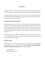
Introduction
1.1 Introduction to Chapter:
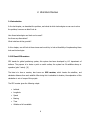
This chapter serves as introduction; it discusses the navigation problem for visually impaired persons
and proposes a solution.
1.2 What Technology assumes:
The technology promises solutions to problems we face in our daily life, as the target of the solution
are mostly people who are not disabled, there seemed to be a gap in the facilities provided to
disabled people by technology. Having said that it does not mean that technology doesn’t provide
solutions to disabled at all, but the problem is most of the research carried out while developing a
product assumes that user is not disabled.
This fact cannot be changed, however equivalent solutions can be developed to fulfil the needs of
disabled people.
There are so many aids that can be developed to help disabled people, e.g. special computers, mobile
phones, special cars etc.
1.3 An Aid for Visually Impaired person:
The focus of this project is to look at the problem which is faced by visually impaired people. Before
going any further, it is worth mentioning here, what do we mean by visually impaired. The term refers
to the person who has difficulty in vision. [1]
The problem faced by visually impaired people is being able to move safely from one place to
another. This includes two things: 1. Mobility and orientation 2. Navigation.
1
In the following discussion when we use term person, we assume that we are talking about visually
impaired person.
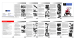
1.3.1 Mobility and Orientation Problem
The first challenge is to move with safety e.g. if a person wants to move 10 yards, he needs to make
sure that the way is clear and he can move safely from one end to the other.
This also assumes that the person has an idea of the
location where he actually is.
Available Solution:
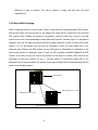
Mobility and Orientation facility is provided by primary
mobility aids such as the White Cane and the Guide
Dog, and more recently enhanced products such as the
UltraCane (see : www.soundforesight.co.uk )
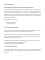
The ultra cane sends out ultra sonic beams, if these
bounce from objects in vicinity, it signals person
Fig 1.1, Ultra Cane [2]
through vibrating buttons in the handle, the different buttons tell where obstacle is, the strength of
vibration tells how far away. [2]
1.3.2 Navigation Problem
Although there are various definitions of navigation, one appropriate for this problem is to be able to
determine location and surrounding features, direction and routing.
We would like to investigate each of these aspects to understand problem of navigation and to
suggest a possible solution.
2
Being able to determine the location means the person knows his exact location, this can be a
name of a place or a distance from any reference.
The surrounding features include names of places around, e.g. a person walking might be
interested in eating something, so he might want to know about any restaurant around.
Direction refers to “the way something or someone moves, faces, or is aimed.” [1]
Routing refers being able to determine the route from one place to another for e.g. if a person is
standing in street A, and he wants to go to street B, what is the route he should follow to get there.
This equally applies to a person who is not visually impaired.
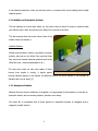
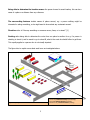
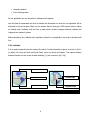
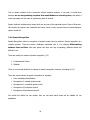
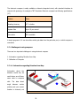
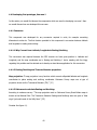
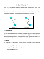
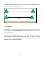
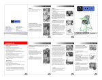
The figure tries to explain more about each term we investigated above.
Am I near my home or ASDA ? (Location)
Is there any restaurant nearby? (Surroundings)
Am I facing Autumn Avenue ? (Direction)
What’s the way to Merrion Center? (Routing)
Fig.1.2 Navigating in a street
3
1.4 Possible Solution:
To achieve a solution, we must look at what information is needed to accomplish the task, and how
we can get that particular information. For navigating correctly, we must have information about all
four points mentioned in the previous section.
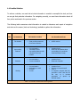
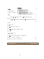
The following table summarizes what information is needed to determine each aspect of navigation
and what are the means (tools and technology) available to gather that information.
S.No.
To Determine
1.
The location
2.
Surrounding
Features
3.
4.
Information needed
Can be gathered from
§
Exact position measured
from some reference
§
A GPS receiver
§
§
Current location
Information about
surrounding features with
reference to current
location
§
§
Location from 1.
Electronic information about
surroundings of a particular
location(electronic map)
Direction
§
§
Current location
Current orientation
§
§
Location from 1.
Electronic Compass.
Routing
§
§
§
§
Current location
Destination to reach
Direction
A route
§
§
§
§
Location from 1.
Decision of person himself
From 3.
A computer program that can
generate a route and can tell
the user, so it includes
generation
of
speech
by
artificial means.
Table 1.1 Information needed and means to gather it.
4
To produce a solution we need
1. All information listed in table 1.1.
2. A device that can store and process that information.
A suitable device can be a pocket PC, which is readily available in markets. A unique user interface will
be required as the person is visually impaired. The interface must offer speech cues to the user
informing him about location, nearby features and routing to other requested locations or features.
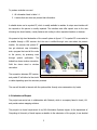
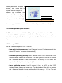
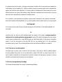
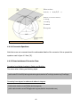
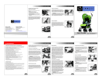
We present a high level abstraction of the overall system in figure 1.3. T he pocket PC is connected to
a satellite through a GPS receiver. And the user is notified through voice cues about his present
location. We assume that pocket PC
has got electronic map information,
and a program that can tell the route
to the person, by producing voice
through
speech
synthesiser.
The
dotted line shows wireless connection.
Solid line shows wired or wireless
connection.
Pocket
The connection between GPS receiver
GPS receiver
Fig 1.3 High Level Abstraction of the system
and pocket PC will either be blue tooth
or cable depending upon the resources provided.
The user will be able to interact with the system either through voice commands or by hands.
1.5 Limitations of Project
The project was carried out in collaboration with Graticule, which is a company based in Leeds, U.K.
and provide custom mapping solutions.
This project is a formal requirement of my MSc.Information Systems degree. As the department of
Computing at University of Leeds imposes a deadline to the submission of the project, it was decided
5
in initial meetings with Graticule that we are going to produce just a prototype which can serve prove
the basic concept.
1.6 Product Market in U.K.
Before doing research for the project it is worth to see whether there is a market for the product or
not. As mentioned in previous section that the project is being carried out with Graticule, and the
company is interested in producing a complete solution, it is necessary for Graticule to have data of
the Blind people because. This data will help them in doing market analysis before producing a
complete solution. Although complete analysis of Market was out of scope of this project, however
some initial pointers have been mentioned, which would be helpful to start the analy sis in future.
I’ve contacted several people to find out about the statistics. The companies contacted through
email/telephone are:
1. Office of the National Statistics.
2. Department of Health U.K.
3. Royal National Institute of the Blind.
Among all the response of the Office of the National Statistics was encouraging, although the
information was not available with them but they provided me help on how to get that information.
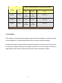
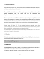
The following table summarizes the information.
It’s impossible to provide complete statis tics here, for details, please refer to. [3, 4, 5]
6
Number of Registered Blind or Partially sighted people
Country
Year
Male
Female
Total
England
2003
Not
Available
Not
Available
156,675 [ 3]
Scotland
2003
8,741
14,816
23,557 [4]
Wales
2001
Not
Available
Not
Available
19,807 [5]
Table 1.2 Blind people statistics
1.7 Conclusion:
In this chapter, we introduced street navigation problem, looked at information we needed to produce
a street navigation aid. We also discussed which devices can provide required information.
We haven’t discussed any specific details of the devices mentioned, we also have not mentioned how
we are going to integrate all devices, what interface would be etc. In the next chapter we will look at
specific details of each device and other tools which will be used in developing a solution.
7
2. Literature Review
2.1 Introduction
In the last chapter, we described the problem, we looked at which technologies we can use to solve
the problem, however we didn’t look at
How these technologies and tools can be used?
Are there any alternatives?
What interface do they provide?
In this chapter, we will look at these issues and would try to look at feasibility of implementing these
tools and technologies.
2.2 GPS and GPS receiver:
GPS stands for global positioning system; this system has been developed by U.S. department of
defence. The purpose is to locate a point on earth surface; the system has 24 satellites always in
operation (plus 3 extra). [6]
The idea is to have a receiver, also known as GPS receiver, which locates the satellites, and
calculates distance from each satellite. After doing this it calculates its location, the explanation of this
calculation is out of scope of this project.
The GPS receiver gives the following output
§
Latitude
§
Longitude
§
Speed
§
Bearing
§
Time
§
Whether a fix Is available
8
§
Magnetic variation
§
Error checking codes
For our application we are interested in Latitude and Longitude.
How this data is represented and how we extract the information we need for our application will be
discussed in the next chapter. Right now we assume that we have got a GPS receiver which is telling
us Latitude and Longitude, and we have a paper which contains mapping between Latitude and
Longitude and names of places.
Before describing, why Latitude and Longitude is useful for our application, we need to describe both
first.
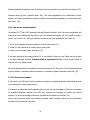
2.2.1 Latitude:
It is an angle measured from the centre of the earth. Consider the earth as sphere as shown in fig 2.1
(a) below. We have got North and South Poles, and a line known as Equator. The angular distance
between Equator line and a pole is called Latitude, [7] and is shown in fig 2.1(b)
North Pole
Equator
Latitude angle
South Pole
Longitude angle
Fig 2.1 (a) [7]
Fig 2.1 (b) [7]
9
The line perpendicular to Equator is
meridians,
also
called
lines
of
longitude. As shown in figure 2.2.
Longitude
angle
is
distance
from
prime meridian (Greenwich England)
to
to the east and west of the Earth
Meridian
surface, as shown in figure 2.1(b) [7]
Fig 2.2 [7]
Now we can appreciate that to locate a point on an earth surface, we use latitude and longitude.
2.2.3 Interface provided by GPS Receiver:
The GPS receiver can be connected to the COM port, through standard interface. The GPS receiver
provides data in NMEA format, this data needs to be interpreted and parsed to use in our application.
Graticule has developed a .Net DLL to accomplish this task. This will further be discussed in next
chapter.
2.2.4 Accuracy of GPS:
There are 3 basic accuracy levels of GPS. These are.
1. Single point positioning accuracy: Level of accuracy is around 10 meters, measured using
a single GPS receiver. The receiver is inexpensive.[8]
2. Differential positioning accuracy: Level of accuracy is from 0.5 to 5 meters. Uses 2 GPS
receivers. One as reference and one as rover. The data is gathered from both the receivers
and a differential calculation is made which results in the accuracy of 0.5-5 meters. More
expensive than Single point positioning system.[8]
3. Carrier positioning accuracy: Level of accuracy is from 1 cm to 30 cm. Uses 2 GPS
receivers. One as reference and one as rover. The data is gathered from both the receivers
and a differential calculation is made which results in the accuracy of 1-30 cm. The main
10
difference is type of receiver. The size of receiver is larger and also they are more
expensive.[8]
2.2.5 Map and GPS mapping:
While considering accuracy we also need to bear in mind about the mapping between GPS receiver
and the map which we have got with us. By mapping we mean that if we have got a very accurate
GPS receiver which provides us accuracy in centimetres, while the map which we got is not that
precise, there won’t be any advantage of using that kind of receiver. Consider figure 2.2. We place an
imaginary grid over the map and assume that each square represents a place on map; area of each
square is 10 m2. We assume that we have got information of each 10 meter square box in our
electronic map. However the GPS receiver we are using gives us information in centimetres. If we
start moving around in a particular square in grid, we will be getting coordinate updates from GPS
receiver on a move of every cm. but as the precision of the map is in meters, there won’t be any
advantage of using such receiver. For e.g. if a person moves 10 centimetres forward and 10 cm
backward from his current position, the position in the map would still be the same(assuming that the
person is on the same square ).
Electronic Map
GPS precision 1 box = 1 cm2
2
Map precision 1 box = 10 m
Fig 2.2 Map and GPS receiver precision.
11
As this project is in initial stages, and we just need to develop a prototype for proof of concept, so we
will be using GPS receiver which provides us single point positioning accuracy. Also the maps which
are provided by Graticule for initial testing are compliant with standard GPS receiver.
2.2.6 Is there any alternative to GPS?
Yes, there is, a Russian system known as Glonass, however it is not fully functional as U.S. GPS
system. Also as we have got all tools to use GPS system we would not indulge our self in looking at
feasibility of implementing Glonass.
There are some receivers available which use both Glonass and GPS system so that required satellites
are always available. Also there is an upcoming European system known as Galileo, so we can say
that in future it would be worth seeing such receivers which integrate all systems and provide more
reliable solution than currently available GPS only receivers.
2.3 The Electronic Map:
Maps are used to represent real world objects which exist in the world [9]. Traditional maps were
paper maps, these days GIS software allow us to create electronic maps. An electronic map is a digital
version of paper map.
We will be using electronic maps to solve our problem, as they provide not just image of the map
but query-able objects, e.g. a street name or intersection or a shop or bus station
entrance.
At this point it is worth elaborating types of map data.
2.3.1 Types of Map Data:
There are mainly two types of map data,[10]
1. Spatial data
2. Attribute data
12
Spatial data describes the location of features and their relationships with each other, while attribute
data describes attribute information about the features. Features are represented by four main
symbols:
§
Point: represents location of feature.
§
Line: represents location of linear features such as rivers, road etc.
§
Polygon: represents a boundary of a region, for example, a territory, a province.
§
Annotation text: They are descriptions of the places, for e.g. name of a territory, length of the
road, Name of a point, location of a point etc. [10]
Having looked at types of map data, we will look how this data is represented in computer.
2.3.2 Structure of Map Data:
The two different ways to store map are:
1. Raster format
2. Vector format
Raster format refers to an image of the map,
this image can be a scanned or computer
generated. The image usually consists of picture
elements, each having a certain grey or colour
value. These can be windows JPEG or Bitmap
files. Figure 2.4 represents a raster map. [10]
Vector format are lines, points and text strings,
they are held in the form of description, and with
Fig 2.4 A Raster map [10]
ordered set of Cartesian coordinates. [10]
13
For example consider a simple map in figure 2.5, which is created by vector information in
corresponding table
Point
Line
Polygon
X
Y
X
Y
X
Y
2
3
3
1
8
4
5
6
9
6
12
4
10
2
11
0
6
3
Fig. 2.5 vector map created from corresponding information [10]
Maps will be used in our project to query the locations (and associated information) the coordinates of
which will be received by GPS.
The Maps will be handled by Map class Lib, which will be discussed in next chapter. After getting the
information of interest, it will be processed if required and transferred to the user through speech.
2.4 Speech Synthesis and Recognition:
In this section, we will discuss speech synthesis and recognition, and in chapter 4, we will discuss how
we implemented the same in our prototype.
We will look at what speech synthesis and recognition is, however we will not discuss the algorithms
used in implementation of a speech synthesiser/recognizer.
14
2.4.1 Speech Synthesis
Why do Speech synthesis and not store just the names of the locations?
This can be understood by simple example, suppose we have 1000 locations in a map, we want to
store all the names in different audio files, in our case we would have 1000 audio files. Although the
file size can be optimized by sampling rate, bits resolution and bandwidth selection, but still
performing I/O for such number of files would require considerable processing power, which we are
unable to provide in a Pocket Pc. However, we can have some audio files for our user interface (this
will be discussed in chapter 4).
Speech synthesis is of two types [11]
§
Concept to speech systems.
§
Text to speech systems.
2.4.1.1 Concept to speech systems
“Concept to speech systems synthesise speech departing from semantic/pragmatic concepts and have
full knowledge of the purpose and meaning of utterances to be synthesised.”[11]
Suppose we have a human robot pet, which has a capability to speak English, of course to make feel
some one that the robot speaks like human, it has to understand when to speak louder and when to
speak soft. Which words to stress and which not.
These systems are under development and lot of research is going on to produce such systems, for
e.g. SPURCE speech synthesis for dialogue systems ( http://
www.essex.ac.uk/speech/pubs/journals/maratea.html)
2.4.1.2 Text to Speech Systems
Text to speech synthesis refers to a system which has a text string as an input and a voice reading
the same text as output. The output is an apparatus that produces a voice that sounds like a human
speech. [11]
15
Text to speech systems do the conversion without semantic analysis, in our case, it would serve
because we are not producing a system that would debate on a burning issue, and rather it
would just speak out the name of a particular place of interest.
Speech synthesis includes many issues which are not part of this particular report. Some of them are:
How closely the output voice resembles the human voice, is there correct interval of pause between
spoken words etc.
2.4.2 Speech Recognition
Speech Recognition refers to recognition of spoken human voice by machine. Speech recognition is a
complex process. There are certain challenges associated with it. For example differentiating
between than and then. Also each person has their own way of speaking, different accent and
different tone.
There are mainly two modes of speech recognition. [12]
1. Command and Control
2. Dictation
There is no universal definition for classes of speech recognition, however, according to [11]
There are several classes of speech recognition for example:
§
Voice verification/Identification
§
Recognition of isolated spoken words
§
Recognition of connected spoken words
§
Recognition of Continuous speech
§
Recognition of Spontaneous speech
We would first define the two modes, then we will state which mode will be suitable for our
application.
16
In command and control mode, a developer has created a certain set of words which are compared to
words spoken by the speaker [12] . While in dictation mode, the speech engine has to compare the
spoken word with the whole dictionary. It is obvious that the command and control mode will be more
efficient and less error prone than dictation mode. Because in command and control mode, we would
have very few comparisons as compared to dictation mode.
In our problem, as we would like our speaker to give certain commands to the system the com mand
and control mode would be applicable, for e.g. when speaker wants to select option one he can speak
“OPTION ONE”
Or he might want to select names of streets starting from the fist letter of the English alphabet, he
can speak
“A”
until this point we have not said anything about the names of the places, as these would be
unknown to us as the application programmer, but an API could be developed that can extract
out the name of places from a map DBF file and can feed those names to the speech recognition
engine. If you are not aware of the map DBF file, you can assume that it is a file containing
information about a map. This will become clearer when we will discuss DBF files in chapter 4.
2.4.3 Can we use any alternative?
We need to give a person cues so that he can move easily, if the person is blind or partially sighted
the next possible thing which he can be aided with is speech. But what if a person cannot hear as
well. It would be difficult but not impossible to propose a solution for that person. However in current
condition we assume that the person can hear properly.
2.5 Choice of programming Paradigm
This section discusses about the chosen Programming paradigm
17
2.5.1 Why Object Oriented Design?
Object Oriented design provides certain advantages over other approaches, first of all it lets
programmer think in the solution domain rather than problem domain.[13] e.g. if in real world we
have an object called speaker, we can have the same object in our object oriented design, which
provides certain functions to us and hides the implementation details. There is so many text written
on object oriented programming which we would not like to repeat here, rather we would give an
example so that reader can appreciate the advantage of object oriented design.
Suppose we have a speech synthesiser class named as
speaker, shown in figure 2.6. Note that we just need to
take care of the interface. We have got functions like
speak, stop, pause. The implemenation of these functions
is hidden and can be changed as long as interface remains
the same. Note the advantage, the user of the class
Speaker
- Volume
- Pitch
- Echo
- Base
Speaker, has just to call the function Speak( ) to
accomplish his task and he don’t have to worry about how
class Speaker is going to do this for him.
Speak ( string to speak)
Stop ( )
Pause ( )
In a nut shell we can say that it eases the modeling,
provides a certain level of abstraction and produces a re-
Fig 2.6 Speaker class
usable code.
2.6 Microsoft .Net Environment for programming in C#.
Software components often require integration with each other, suppose we have a software
component developed in C++ which for some reasons wants to talk with a software component
developed in Java. Providing interface in-between is not a trivial task as both are different paradigms
and have their own architecture and interface.
Also the users are not restricted to desktop only applications, as in our case, after complete
development, we would like our software to be deployed on pocket pc.
18
Software developers realized a need of software which is accessible to any one from any device [14].
Microsoft came up with a solution called .Net. That allows applications to be distributed to small
devices, and allows applications created in different programming languages to communicate with
each other. [14]
2.6.1 Can we use any alternative?
In meeting of 25th May 2005 I advised Jim Hogg (Director Graticule), that I am more comfortable with
using Java, but he advised me that they’ve got some classes developed in C# so it would be better if
you do your work in C#. Although solutions exist to convert Java applications to C# such as
1. JLCA, Java language conversion assistant, converts Java code to C#
2. Visual J# .Net, extension for writing code in java syntax
3. Jbimp, use for migrating java .class files. [15]
It has been decided in the meeting that as C# is very similar to Java so it won’t take me long to learn
it. Another advantage was that Graticule staff is experienced in C#, so they would be able to
help me out in my whole project.
Note that although tools are available to convert java code to C#, they are not 100 percent applicable
at every instance, sometimes manual conversion is required to support automatic conversion.[15]
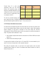
2.7 The Electronic Compass:
In this section we will give a brief introduction to electronic compass, and state what challenge need
to be addressed in future developments.
In chapter 1 we talked about the navigation and we point out that knowledge of direction is necessary
for complete navigation solution. Since GPS only provides the knowledge of position and not the
direction, to get the knowledge of direction, the electronic compass can be used. [16]
We are not concerned about how electronic compass works internally; rather we are interested in
knowing only the interface it provides.
19
The electronic compass is easily available as discrete integrated circuit, with standard interfaces to
connect with pocket pc, for example a TNT Revolution Electronic compass has following specifications:
[17]
Feature
Value
Heading Accuracy
0.5o or better
Update Rate
Up to 20 per second
Connection
RJ12, available
A simple program in C# can be written which gets data from the particular port, on which compass is
connected.
2.7.1 Challenges in using compass:
There are two important challenges in using electronic compass.
1. Information regarding Direction from Map
2. Calibration of Compass
2.7.1.1. Information regarding Direction from Map
Information
about
the
direction would only be
useful when we will have
some data to compare
with.
angle
The
data
between
about
certain
position and your current
location is obviously not
Figure 2.7 Angle calculation
20
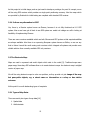
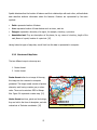
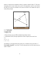
present in a map but can be calculated at runtime, for example, consider the figure 2.7. Blue star is
representing person’s current location and we want to find angle between person’s current direction
and ASDA. As we know the coordinates of the person and ASDA we can calculate this angle by
making following triangle.
X2, Y2
C
A
X1, Y2
X1, Y1
Figure 2.7 (b) Angle calculations
X1 , Y1: Persons location
X2 , Y2: Asda’s location
B: imaginary X-Axis
C: imaginary Y -Axis
A: Distance between person and ASDA, calculated through distance formula
θ : Angle between A and B, this angle represents the number of degrees person need to turn.
Since,
Sin ( θ ) = C/A
θ = Sin -1 (C/A)
The calculated θ, is the angle that the person needs to turn. But what if person moves theta + 2o
Do we need to stop him? Yes, but how? This will be discussed when we will be discuss close loop
system in chapter 4.
21
2.7.1.2 Calibration of Compass
The compass need to be calibrated correctly with the person, it cannot be attached with PDA, as the
user cannot fix PDA’s position with respect to his body. The Challenge is to attach the compass to a
person in a way which is not annoying to him. We will leave this issue for future development of the
project.
2.8 Conclusion
In this chapter we looked at, related technologies, and their interfaces. Now we have idea how we
can use these tools and technologies to solve street navigation problem. Having this knowledge in
next chapter we will design our system.
22
3. System design.
3.1 Introduction:
In the last chapter, we looked at different tools and technologies available, we looked at interfaces
they provide, based on that knowledge in this chapter we will design our system. Also we will identify
main user requirements. We would use standard UML notations where appropriate.
3.2 What is UML and why use UML:
[18] States: “The Unified Modeling Language (UML) is a graphical language for visualizing,
specifying, constructing, and documenting the artifacts of a software-intensive system. The UML
offers a standard way to write a system's blueprints, including conceptual things such as business
processes and system functions as well as concrete things such as programming language
statements, database schemas, and reusable software components”
3.3 Why UML?
UML is the preferred way of doing modeling as it is the world wide standard language for modeling
which is compatible across platforms. Before UML was invented there were so many different
modeling languages. After its invention it became world wide standard.
Also there are many UML modeling tools available by Software Market Leaders like Microsoft, IBM,
Rational etc and they support the standard UML modeling. So this makes UML the preferred way of
modeling against any other modeling language
23
3.4 System Requirements (from user perspective)
In chapter 1, we discussed what the essential constituents of navigation are. Now we present
corresponding use cases. Use cases provide overview of the usage requirements [19]
“A use case describes a sequence of actions that provide a measurable value to an actor.” [20]
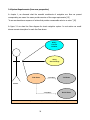
In figure 3.1 we draw Use Case diagram for street navigation system. In next section we would
discuss scenario description for each Use Case drawn.
Query
Current
Location
Query
Surroundings
Find Route
<<include>>
Tell Route
Person
<<include>>
Figure 3.1 Street Navigation Aid Use Case Diagram
24
Guide Route
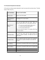
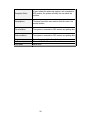
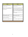
3.4.1 Scenario Description for Use cases
In this section we discuss scenario description for each use cases which are drawn above. The table
format is taken from [21].
Use Case Name:
Query Current Location
Primary Actor:
Person, user of the system
Value Proposal to
Actor(s)
Knowledge of his current location.
This use case begins when user select “Query your
current location option from 3 initial options which are :
Basic Course of
Events:
1. To query your current location please press 1
2. To query surroundings please press 2
3. To find a route please press 3.
When user selects the option 1, the system will tell user
its current location.
Alternative Paths:
If a user start moving with this option selected, the
system on update of position, will notify the user of its
new position.
Exception Paths:
If users select this option and system is not connected to
GPS receiver, the system will notify the user about the
problem.
Pre-conditions:
The system is connected to GPS receiver and getting data
Post-conditions:
The system is connected to GPS receiver and getting data
Project:
Author:
Print Date:
Street Navigation Aid for Visually Impaired
Salman Abdul Ghaffar
08/09/2005
25
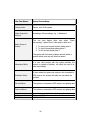
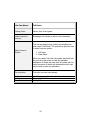
Use Case Name:
Query Surroundings
Primary Actor:
Person, user of the system
Value Proposal to
Actor(s)
Knowledge of Surroundings, e.g. a Restaurant
Basic Course of
Events:
This use case begins when user select “Query
Surrounding” option from 3 initial options which are :
1. To query your current location please press 1
2. To query surroundings please press 2
3. To find a route please press 3.
The system will find names of places around (within a
specific radius) and user will hear the names.
Alternative Paths:
If a user start moving with this option selected, the
system on update of position, will notify the user of its
new surroundings.
Exception Paths:
If users select this option and system is not connected to
GPS receiver, the system will notify the user about the
problem.
Pre-conditions:
The system is connected to GPS receiver and getting data
Post-conditions:
The system is connected to GPS receiver and getting data
Project:
Author:
Print Date:
Street Navigation Aid for Visually Impaired
Salman Abdul Ghaffar
08/09/05 20:37
26
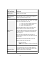
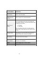
Use Case Name:
Find Route
Primary Actor:
Person, user of the system
Value Proposal to
Actor(s)
The system will give user an option either to hear the
route or to guide him through the way.
This use case begins when user select “Find Route”
option from 3 initial options which are :
1. To query your current location please press 1
2. To query surroundings please press 2
3. To find a route please press 3.
The system will then ask the user to enter letter from
which he wants to hear the names of the places.
Basic Course of
Events:
The system will find names of places and will give option
to hear the names in a sequence by moving back and
forth through list.
Once user selects a particular name of a place, the
system will echo the name of the place selected. And will
find the route.
After finding the route the system will give user two
options, through which user can either
1. Just hear the route.
2. Allow system to guide him all the way through the
route.
Alternative Paths:
If user presses a letter from which system cannot find
any names of the places, the system will notify the user
and will ask him to enter the letter again.
27
Exception Paths:
If users select this option and system is not connected to
GPS receiver, the system will notify the user about the
problem.
Assumptions:
The place from which user wants to find the route is his
current location.
Pre-conditions:
The system is connected to GPS receiver and getting data
Post-conditions:
The system is connected to GPS receiver and getting data
Project:
Author:
Print Date:
Street Navigation Aid for Visually Impaired
Salman Abdul Ghaffar
08/09/2005
28
Use Case Name:
Tell Route
Primary Actor:
Person, user of the system
Value Proposal to
Actor(s)
Knowledge of the Route to take to reach destination.
Basic Course of
Events:
This use case begins when system has completed use
case named “Find Route” The system than gives the user
to select from two options.
1. Tell Route
2. Guide Route
When user selects Tell route, the system just briefly tells
the user the route to take to reach the particular
destination. By briefly we mean that the system will only
notify the names of streets and intersections which user
need to take to reach the destination.
Pre-conditions:
The route has been found already
Project:
Author:
Print Date:
Street Navigation Aid for Visually Impaired
Salman Abdul Ghaffar
08/09/2005
29
Use Case Name:
Guide Route
Primary Actor:
Person, user of the system
Value Proposal to
Actor(s)
Able to navigate to the selected destination.
This use case begins when system has completed use
case named “Find Route” The system than gives the user
to select from two options.
Basic Course of
Events:
3. Tell Route
4. Guide Route
When user selects Guide route, the system goes into
state in which it starts guiding the user about the route
to take.
Exception Paths:
While telling the route if the GPS is disconnected the
system will notify the user about the problem.
Pre-conditions:
The route has been found already
Post-conditions:
The user is at his destination
Project:
Author:
Print Date:
Street Navigation Aid for Visually Impaired
Salman Abdul Ghaffar
08/09/2005
30
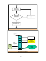
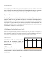
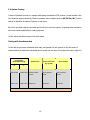
3.5 System Architecture
In this section, we present the overall architecture of the system by drawing a component diagram.
We’ll identify the components needed and also define boundaries of our system. In section 3.5.2 we
will state function of each component.
3.5.1 Component Diagram.
UML component diagram allows defining overall architecture of the system, the components present
and interfaces between them. [22]
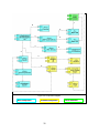
Figure 3.2 indicates:
§
The basic system, components in blue colour.
§
Further refinement of our system, Components in Light Yellow Colour
§
Components which can be added for future enhancements. Components in Green Colour
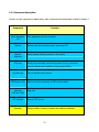
In the following table we state what each stereotype indicates in figure 3.2. [20]
Stereotype
Indicates
<< application >>
Front end of the system, collection of screens
and controller classes
<< library >>
An Object or Function Library
<< file >>
A data File
<< table >>
A data table
<< hardware >>
A hardware component in our system
Table 3.1 Stereotypes
31
J
B
D
C
D
C
E
A
F
G
H
I
Figure 3.2 Component Diagram
Basic Components
Extended Components
32
Future Extension
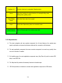
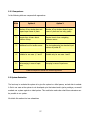
3.5.2 Component Description:
Function of each component is stated below; each component will be discussed in detail in chapter 4.
Component
Street Navigation
Aid
Speaker
Function
Main Application and User Interface
Speaker class that abstracts speech synthesiser API
Speaker
Hardware
Actual speaker hardware present in the system
Converter
Library to provide data conversion functions. For e.g. conversion
between latitude and longitude to Easting and Northing.
Map Class Lib
GPS Receiver .Net
Map files
(.DBF and .SHP)
GPS Receiver
Gazetteer
Class to handles map functions
Class to provide connectivity to GPS receiver device.
Map data
Physical GPS receiver.
Contains tables of names of places and relative coordinates.
33
Gazetteer Lib
Router
Route Finding
Engine
Graph
Graph Extractor
Provides functions to manipulate Gazetteer data.
Class that handles all routing functions, for example telling route,
finding route, guiding route.
Class that finds route from a graph
Graph data. Represents places as connected nodes.
Class to Extract graph from existing map data.
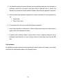
3.5.3 Dependencies:
A. The street navigation aid uses speaker component for all voice features, the speaker uses
speech synthesiser and speech synthesiser abstracts the connection with hardware.
B. The main application component also uses converter component to convert any quantity from
one unit to another if needed.
C. For handling maps, the main application component uses, Map Class Lib, and to receive GPS
data, it uses GPS .Net.
D. The Map class lib provides all necessary functions to handle maps
E.
GPS .Net provides an interface to connect main application component to GPS device.
34
F. The Gazetteer contains the names of places and corresponding coordinates; this information is
particularly useful when we need to find places within a particular area of interest. The
Gazetteer Lib provides an interface between Gazetteer table and main application component.
G. Router provides main application component all functions necessary for routing purposes, for
e.g.
§
Finding route.
§
Telling route to user.
H. To accomplish this it also uses services from Speaker component.
I. Route finding algorithm is implemented in Route finding engine component, which require a
graph to find a route between two places.
J. At present we’ve manually created in graph, while in future, a separate component can be
developed (Graph Extractor) as shown in figure, which can extract Graph from .Shp and .DBF
files.
3.6 Conclusion:
We identified the usage requirements and presented the system design in this chapter, next chapter
will discuss the implementation details of the designed system.
35
4. Software Components and
System Implementation.
4.1 Introduction:
In the last chapter we designed our system, we identified individual software components, and in this
chapter we would build or use those software components. We will discuss implementation details
and would draw class diagrams where appropriate.
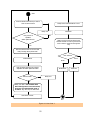
If necessary we would draw, Activity Diagrams (UML equivalent to flow charts).
We would start from discussing individual components and at the end we would discuss integration of
all these components into main application.
The implementation was divided into 4 phases:
1. Learning the tools.
2. Developing a simple map application to demonstrate the understanding of the tools learned.
3. Developing first prototype, which accommodates use case 1
4. Adding more functionality to accommodate use case 2 and 3.
4.2 Learning the Tools
In the meeting of 1st June, with Jim Hogg, Director Graticule, he advised me to learn the tools
necessary to develop the application.
4.2.1 Learning Microsoft .Net and C# .Net:
To learn Microsoft .Net, Graticule provided me Microsoft .Net IDE. It took some time to get familiar
with the IDE, writing object oriented code, using DLLS, etc. The people at Graticule help me a lot to
learn the Microsoft .Net and use of C# programming language.
4.2.2 Learning MapClassLib:
Map class Lib is a .Net DLL developed by Graticule. The use of Map Class Lib requires Licence which
was provided us by Graticule Ltd.
36
I learnt Map Class Lib with the help of a User Manual; MapClassLib .Net version 1.0, this is a thick
user manual and provided me chance to learn so many things. We won’t discuss all functionalities
present in MapClassLib, due to space limitation.
4.2.2.1 What is MapClassLib?
There are thousands of applications available in the market that deals with geography. The thing
common among all these application is electronic map. Handling map has some common functions,
for example, loading a map into application, zooming into map etc.
MapClassLib is a library, which provides many kind of map handling functions; it allows developers to
quickly build custom applications [10]. It can be used with any .Net compliant programming
language.
Map class lib also contains a caching system, which is particularly useful for using large maps within
custom applications.
4.2.2.2 What can we do by using MapClassLib?
§
Map class lib allows importing different format data into application for example it supports
both SHP/DBF and MIF/MID formats. (These formats will be discussed shortly)
§
Allows to Pan, Scroll, Zoom, Change scale with efficient caching system.
§
Allows easy access to map data.
§
Allows editing and revising vector map objects.
§
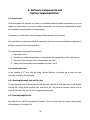
Can draw map objects with different styles of lines, polygons etc.[10]
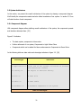
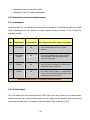
In our application, we’ve used map class lib to load the maps, update the map display at run-time,
getting attribute data of particular location of a map. The following is a piece of code from the
application.
37
1
2
3
4
5
6
7
8
9
10
11
12
13
14
15
Vertex v = new Vertex(latitude,longitude) ;
VectorObject2D[ ] vectorObjects =
myVectorSheet2.queryObjectsAtPoint(v, 10);
if ( vectorObjects.Length != 0)
{
String [ ] vals =
myVectorSheet2.AttributesDb.getAttributeValues(vectorObj
ects[ 0 ].GUID);
Speaker.speak(vals[5]);
}
In line 1 we are getting a vertex at particular latitude and longitude, on line 4 we are querying objects
at this particular vertex, the function return the information present in database file regarding that
vertex.
We than extract out the information which we need, for example in line 9 we are getting all that
information in an array of string. Now we can use that information, for example the name of the
place is on index 5, so we are saying to speaker to speak out the name of place for us on line 14.
4.2.3 Learning GPSClassLib:
GPSClassLib is also a .Net DLL developed by Graticule. The use of GPSClassLib requires Licence which
was provided us by Graticule Ltd. It provides an interface between the application and GPS receiver.
The GPSClassLib reads data from the COM port of the system. The data arrives in NMEA format,
which contains information of speed, latitude, longitude, time etc. [6]. This report does not discuss
NMEA format, for details please see, http://www.nmea.org
38
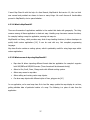
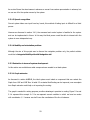
We can write code in event handlers, which can be created using GPSClassLib. For example, following
code displays event hander for position update event. On line 4, 5, 6 we are writing the new position
received on console for test purposes.
1
2
3
4
5
6
7
8
private void GPSTestApp_PositionReceived( double latitude , double longitude )
{
Console.Write ( "position update:\n" );
Console.Write ( "\t\tlatitude = {0}\n" , latitude ) ;
Console.Write ( "\t\tlongitude = {0}\n\n" , longitude ) ;
}
4.2.4 Learning how to Integrate MapClassLib and GPSClassLib:
The next step was to learn using MapClassLib and GPSClassLib together; this was a trivial task and
took me only few hours to learn.
4.3 Developing a simple map application
The task of developing simple application was
§
To learn handling maps. (loading, panning, zooming, getting map data)
§
Learn different formats of maps and their handling in MapClassLib
§
Integrating MapClassLib and GPSClassLib
Graticule provided test GPS data to test the application without actually connecting it to GPS. That
data was helpful and allowed me to develop application while sitting in office. Developing application
included experimenting with following files: .DBF files, .SHP files, and .MIF files, .MID files.
.SHP file, stands for shape file, it contains map information in vector format; it is in standard ESRI
format. The .DBF file is corresponding database file, which contains attribute information about .SHP
file [23]. Sim ilarly, the .MIF file stands for MapInfo Interchange Format, the vector information
reside in MIF file and corresponding attribute information is contained in .MID format. [24]
39
4.4 Developing first prototype, Use case 1
In this section, we would first discuss the components which are used in developing use case 1 than
we would discuss how we developed this use case.
4.4.1 Converter:
This component was developed for any conversion required in units, for example converting
kilometres to miles etc. The first function provided in this component is conversion between latitude
and longitude to easting and northing.
4.4.1.1 Why Convert from Latitude/Longitude to Easting/Northing
This conversion was required because the GPS receiver we have gives position in Latitude and
Longitude, and the map coordinates are in Easting and Northing. I had a meeting with Jim Hogg
regarding this problem and he advised me to develop a stand-alone application for this conversion.
4.4.1.2 Easting/Northing and Traverse Mercator projection:
Map projection: “A map projection is any function which converts ellipsoidal latitude and longitude
coordinates to plane easting and northing coordinates. Ordnance Survey maps use a type of
projection known as the Transverse Mercator (TM).” [25]
4.4.1.3 Reference to calculate Easting and Northing:
According to ordnance survey: “The map projection used on Ordnance Survey Great Britain maps is
known as the National Grid. The Transverse Mercator Eastings and Northings axes are given a ‘false
origin’ just south-west of the Scilly Isles”. [25]
Consider the figure 4.1,
40
Where we have ,
P ( X,Y )
=
F ( P(λ,θ
) )
Where F is conversion function,
X- Easting
Y-Northing
λ-Latitude
θ-Longitude
Figure 4.1 [26]
4.4.1.4 Conversion Equations:
Note that we are not concerned about the mathematical details of the conversion. But we present the
equations used in figure 4.2 from [25].
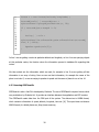
4.4.1.5 Some interfaces of Converter Class:
Converting from latitude longitude to Easting and Northing:
The return value is Easting and Northing object
public static EN LLtoEN(LatLong latitudeLongitude,double latTrueOrigin,double longTrueOrigin)
Converting from degrees to radians and radians to degrees:
Public static double convertToRad (double degrees)
public static double convertToDeg(double degrees,double mins,double secs)
41
Parameters:
a-b
n=
a+b
? = aF0 (1-e 2Sin 2φ ) -0.5
? = aF(1e )(1-e Sin φ )
0
2
?=
2
2
a - semi-major axis = 6 377 563.396
b - semi-minor axis = 6 356 256.910
N0 - northing of true origin = -100 000
E0 - easting of true origin = 400 000
F0 - scale factor on central meridian = 0.9996012717
φ0 - latitude of true origin = 49° N
λ0 - longitude of true origin and central meridian = 2° W
-1.5
?
-1
?
C1
C2
5 2 5 3
21 3
2
(1+n + 4 n + 4 n )(φ -φ0 )- (3n+3n + 8 n )sin( φ -φ 0 )cos(φ -φ0 )
M= bF0
+( 15 n 2 + 15 n 3 )sin(2( φ -φ ))cos(2(φ -φ ))- 35 n 3sin(3( φ -φ ))cos(3(φ -φ ))
0
0
0
0
8
8
24
C3
I = M + N0
?
sinφ cosφ
2
?
III =
sinφ cos 3φ (5 - tan 2φ + 9? 2 )
24
?
IIIA =
sinφ cos 5φ (61 -58 tan 2φ + tan 4φ )
720
IV= ? cosφ
II =
ν
ν
cos3φ ( − tan 2 φ )
6
ρ
ν
VI =
cos5 φ (5-18 tan 2φ +tan 4φ +14? 2 -58(tan 2φ )n 2 )
120
N=I+II( λ − λ0 ) 2 +III(λ − λ0 ) 4 +IIIA(λ − λ0 ) 6
C4
E= E 0 +IV(λ − λ0 ) +V( λ − λ 0) +VI(λ − λ 0 )
C5
V=
3
2
5
2
Figure
4.2 Traverse Mercator Equations
AB = x 2 - (x1 ) + y 2 -(y
1)
42
from [25]
4.4.2 Speech Synthesiser:
We’ve used Microsoft Speech SDK, which provides speech synthesiser as well as speech recogniser,
we’ll discuss speech synthesiser in this section.
The speech API provide interface between Text to speech engine and our application, which results in
reduced
development
time.
The
speech
SDK
can
be
downloaded
from
http://www.microsft.com/download
When we implemented Speech SDK for the first time we got some bugs in our application, one of
them was that in a sequence of operations, SDK sometimes skip the speaking operation and perform
code wh ich is written after that. That problem was solved by reading more documentation. That was
basically the facility provided by SDK and is known as Synchronous and Asynchronous Speaking.
Microsoft Speech SDK states [27] “The two speaking functions can generate speech either
synchronously (function does not return until text has completely spoken) or asynchronously (function
returns immediately but continues speaking as a background process”.
The Speech SDK also allows custom word pronunciation facility. This facility has not been used in this
version, but will be used in future versions.
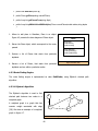
4.4.3 Speaker:
The Speaker class provides further abstraction over Microsoft Speech SDK. E.g. it provides a function
which takes a string as an argument and speaks it out.
Public void Speak ( String toSpeak )
4.4.4 Use Case 1:
We already described this use case in chapter 3; in this section we would mention the steps taken to
implement this use case. Figure 4.3 shows initial execution of application.
The application starts with giving user 3 options to select from. Which are 3 use cases.
43
Speak out the
available options
No
Has user selected
option within a
particular time
Notify
User
Yes
Start
Executing Use Case
Figure 4.3 Initial Execution Path of Application
Use case 1
Code
GPSClassLib
Convert to
Easting/Northing
Query
name from
map .dbf
files
Your current
location
Is XXX
Figure 4.4 Use case 1 sequence
44
HCI Consideration:
A user might forget or could not hear properly when application speaks out the first 3 option in first
place in that case If user doesn’t select anything within a particular time, the application reminds user
that it is waiting for user input and speaks out the options again. This is shown in figure 4.3.
Sequence of use case:
On selecting “Find your current location”, the system starts event handler that executes when user
change his location or if user has selected the option for the first time. The application gets the
latitude and longitude from GPS receiver, converts it into corresponding Easting and Northing, find
out the name of the nearest place from map .dbf files, this includes call to MapClassLib function. After
getting the name of the location, it calls speaker class’s Speak function, which speaks out the user’s
current location. The sequence is shown in figure 4.4.
4.5 Adding more functionality; Use case 2 and 3
Recall from Component Diagram presented in chapter3 (figure 3.2), we divided our components in
basic and extended components; the extended components are used in developing use case 2 and 3.
In this section we would discuss the extended components and also use case 2 and 3.
4.5.1 Gazetteer:
A Gazetteer is a table that contains names of
places
and
their
corresponding
Easting
ID
Name
Easting
Northing
and
Northing values in a map. Figure 4.5 illustrates a
particular Gazetteer.
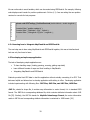
4.5.2 GazetteerLib :
Figure 4.5 Gazetteer
This class provides an interface between application and Gazetteer. It provides all
necessary functions to query the gazetteer data, the interfaces of the functions and brief explanation
are given below.
45
1. public void addPlace(Place pl)
2. public Place getPlace(string nameOfPlace)
3. public ArrayList getPlacesFrom(string Alph )
4.
public ArrayList plWithinXAndStWithAlpha( Place currentPlace,double radius,string alpha
)
1. Allows to add place in Gazetteer, Place is an object.
Figure 4.5 presents the class diagram of Place object.
Place
String name
Double Easting
Double northing
2. Return the Place object, which corresponds to the name
passed.
String getName()
Double getEasting()
Double getNorthing()
3. Returns a list of Places that starts from particular
alphabet.
Figure 4.6 Place class
4. Returns a list of Places, that starts from particular
alphabet and are within a particular radius.
4.5.3 Route Finding Engine:
The route finding engine is implemented as class PathFinder, using Dijkstra’s shortest path
algorithm.
4.5.3.1 Dijkstra’s Algorithm
The Dijkstra’s algorithm is used to find
A
shortest path between two nodes in a
weighted graph.
C
4
1
A weighted graph is a graph that has
B
numeric weight associated with edge
[28]. We show an example of a weighted
2
4
E
1
10
D
graph in figure 4.7.
Figure 4.7 A Weighted Graph
46
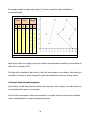
Consider Figure 4.7,
representing
nodes
in
which
circles
and
lines
drawn
Path
Cost
1
B -> C -> E
8
2
B -> D -> C -> E
7
3
B -> D -> E
12
S.no
between circle representing edges, each
edge has an associated weight with it. Let’s
consider that we want to go from node B to
node E, there are 3 possible Paths, which
we summarize in table 4.1
The total cost associated following each
Table 4.1
path is stated Cost column, The Dijkstra algorithm finds the shortest path, in this case the shortest
path which Dijkstra’s algorithm would find, is path 2. This has lowest cost of 7.
4.5.3.2 Distance Calculation between nodes:
As explained above that Dijkstra’s algorithm finds shortest path given two nodes, the question arises
how we have calculated distance between nodes and assign weight to edges. Before explaining
distance calculation we would state as assumption we took while working with .SHP files.
Unfortunately the .SHP and .DBF files which we used in our project do not contain any information of
Graph. This problem could be addressed in 2 ways.
1. Write a software component that extracts out Information from .SHP and .DBF files and create
graph for us.
2. Assume that we have already got a graph.
In meeting with Ken Brodlie and Brian Hoyle on 15th August 2005, it has been decided to go for
option 2 as we have not enough time to write a separate component.
After stating the assumption made, we come back to the original question, which was about
calculating distance between two nodes. We calculated actual distance between two nodes by
distance formula, which is:
47
[29]
Figure 4.8 (A) represents the distance we calculated through distance formula, figure; 4.8(b)
represents the actual distance between nodes.
The CalculateDistance method is present in class Gazetteer. In future if we build a component that
extracts out the actual graph, the implementation of this component can be changed.
A
A
A
Actual
Distance
Actual
Displacement
B
B
Figure 4.8 (A)
Figure 4.8 (b)
4.5.3.3 Source Code
The basic source code is taken from [30], and some modifications were done to suit the application.
The source code was in java, and is converted into C#, line by line.[10] provides useful information
for converting code from Java to C#. Some helper collection classes which were not present in C#,
were also taken from [31]. For example, Priority Queue class and HasedSet class
4.5.4 Router
The router class is an abstraction for all routing functions. The interface of some functions is
mentioned below.
1. public void guideRoute ( Route rt )
2. public Route findRoute ( Place source,Place dest )
3.
public void tellRoute ( Route rt )
48
1. Given a Route object, it guides user the route. This function assumes the system as closed
loop system. We discuss the concept of closed loop system in section 4.5.4.1.
2. Given a source and destination. This function returns the Route object.
3. This function speak outs the route briefly.
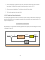
4.5.4.1 Closed Loop System Explanation:
The Route guiding algorithm is based on closed loop system concept, the GPS receiver measures the
person’s actual position, and a comparator compares the actual position and required position. The
output of comparator is E.
E = Actual position – required position
After calculation E is feed to Route calculating algorithm which guides person accordingly this concept
is illustrated in figure 4.9
E
+ 3
Route Telling
Algorithm
Person
GPS
Receiv
er
Figure 4.9 Close loop system
49
Person’s
position
Guidance
The Route object includes the Place source, Place destination and List of places through which the
user can get to the destination. Figure 4.10 represents the Route object.
Having discussed all components which are used in construction of use case 2 and 3, now we would
discuss execution sequence of Use case 2 and 3.
Route
Place Source
Place Destination
List Route;
Place getSource( )
Place getDestination( )
List getRoute( )
Figure 4.10 Route class
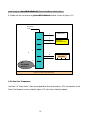
4.5.5 Use Case 2 sequence:
Recall that Use case 2 is “Query Surroundings”. Repeating from use case 1 that the application starts
with giving user 3 options to select from. Which are 3 use cases. Please refer to figure 4.3 to
understand the initial execution path of the application. Once the user has selected Use case 2 the
following sequence occurs. The sequence is similar with use case 1. Except at the end the application
gets the surroundings information from Gazetteer class.
1.
Get the Current Latitude and Longitude.
2,3. Convert to Corresponding Easting and Northing
4,5. Get the name of the current location of the user.
6,7. Get the names of the surrounding places within a particular radius by calling the following
Gazetteer function
50
public ArrayList placesWithinRadiusX( Place currentPlace, double radius )
8. Speaks out the List returned by placesWithinRadiusX method. (shown in figure 4.11 )
Use case 1
Code
1
2
3
GPSClassLib
Convert to
Easting/Northing
4
5
6
7
Gazetteer
8
The
surrounding
places are….
Figure 4.11 Use Case 2 Sequence
4.5.6 Use Case 3 sequence:
Use Case 3 is “find a Route”. After normal application flow as discussed in 4.5.5 and selection of Use
Case 3 the Sequence occurs is stated in figure 4.12 in the form of activity diagram.
51
Start
Press the button from which you wish to
hear the street names
Notify Source and Destination to user
Notify user
Find Route
No
User presses an
Alphabet
Within particular time
Notify user that route has been found
And ask whether he wish to just hear the
route or want to guide him through the
way
Yes
Echo the selected letter to the user and
notify “Finding names please wait”
User selection
Load Gazetteer
Guide
Find all names starting from selected
Alphabet and within particular radius
Names found?
Guide Route
Notify user
No
Yes
Notify user that “ List of names have
been found, press 1 to move forward,
press 2 to move backward, press 3
to select”. Any other key for main menu.
User selects a name
End
Figure 4.12 Use Case 3
52
Listen
Tell Route
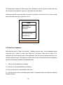
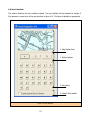
4.6 User Interface:
This section describes the user interface created. The user interface will be evaluated in chapter 5.
We represent a screen shot of the user interface in figure 4.13. The figure is labelled as appropriate.
1. Map Display Area
2. Option buttons
3. Key Board
4. Speech Clue enabler
Figure 4.13 User Interface
53
The user interface assumes that we have a tactile key board which can be pla ced above the pocket
PC screen these types of screen are already available in the market. An example is included in
Appendix D.
1. The map display area, person’s current position is always in the centre of the map.
2. Option selection buttons, initially these buttons represent selection of particular use case.
However the functionality of these buttons change according to menu. For example while
executing use case 3 when list of the names of the places is found, button 1 and 2 are used
for moving back and forth in list and button 3 is used to select a particular place. The user is
always notified of change of the function of these buttons.
3. Key board, used when information regarding street names etc is required.
4. This allows enabling speech clues, when user will move his finger over the screen he would be
able to listen the name of the key on which his finger is (if box is checked). This will help in
avoiding any unnecessary errors and fast learning of key locations over screen.
4.7 Conclusion:
In this chapter we discussed components used in each use case and their implementation details.
The next chapter will discuss system testing, evaluation and future extensions.
54
5. System Evaluation and Testing
5.1 Introduction:
This chapter discusses about user interface evaluation and evaluation of current system against the
ideal system. We would also discuss the enhancements that can be made to our system to make it an
ideal system. At the end we would present some functional testing of the system.
5.2 User interface Evaluation:
The user interface was presented in section 4.6. Where we briefly explained about particular features
of the interface as well. The user interface presented contains keys from A-Z. Although we provided
an option for speech clue, still this interface is difficult to use for a person who is visually impaired. So
we discuss another option in next section.
5.2.1 Another Approach for user interface:
To make user interface simpler we can have just 3 option button (please refer to figure 4.13)
available, with no key board.
But in this kind of interface, reaching to a particular option would take too long as compared to user
interface presented in section 4.6
We try to understand this concept with an example.
Suppose a person wants to find a route from his current location (Montrose Street) to Zooper Street.
We draw 2 columns below and state steps associated with each option. We represent the user
interface of section 4.6 as option 1, and the other interface as option 2.
55
Option 1
Option 2
Please select from the following options
Please select from the following options
User selects use case 3
User selects use case 3
System asks to input the alphabet from which
user wants to hear the names of the streets
System asks to input the alphabet from which
user wants to hear the names of the streets
User presses letter Z.
System notifies user that he can move back and
forth in a list of alphabet by pressing option 1
and 2 and can select an alphabet by pressing
option 3.
User presses option 2 button 26 times to go to
end of list to select Z.
System finds 5 names and gives option to user
to hear the names by moving back and forth in
list controlled by button 1 and 2.
System finds 5 names and gives option to user
to hear the names by moving back and forth in
list controlled by button 1 and 2.
User moves to second position in list and selects
a particular street by pressing 3.
User moves in list and selects a particular street
by pressing 3.
Total key strokes to complete use case: 5
Total key strokes to complete use case: 30
Table 5.1 steps involved in user interface option 1 and 2
56
5.2.2 Comparison:
In the following table we compare both approaches.
S.No
Option 1
Option 2
1
Number of key strokes does not
depend upon name of place.
Number of key strokes depends upon
name of place and can vary greatly
2
Require time to learn about
position of keys
Require time to learn navigating
between menus
3
Additional cost for tactile screen.
Can be implemented via standard input
buttons of pocket PC
4
Suitable for use case 1, 2 and 3
Suitable only for use case 1 and 2
5
Not annoying in case of input
error
Annoying in case of input error.
Table 5.2 Comparison of both user interface approaches
5.3 System Evaluation
The best way to evaluate the system is to give the system to a blind person, and ask him to evaluat
it. But in our case as the system is not developed up to that extent and is just a prototype, we would
evaluate our system against an ideal system. This would also make clear what future extension can
be possible in our system.
We divide this section into two subsections
57
§
Evaluation in terms of using the system.
§
Evaluation in terms of system development.
5.3.1 Evaluation in terms of using the system:
5.3.1.1 Navigation:
Recall form table 1.1, we identified four requirements of navigation. In the following table we re-state
these requirements and see whether we have provided solution for those, if not is there any
extension possible.
S.No.
Requirement
Solution Exists
What Extensions can be made in our system
1.
The location
Yes
Can use differential receiver to increase
accuracy
2.
Surrounding
Features
Yes
Can use more detailed map, which contains,
more information regarding places around
than current test map
3.
Direction
No
Use of Electronic Compass, the challenges are
already discussed in section 2.7
4.
Routing
Yes
The basic routing system is implemented,
however it needs further enhancements which
are discussed in section 5.3.2.1
Table 5.3 Evaluation in terms of current system and future extensions
5.3.1.2 Voice Output
The voice output from the system should be 100% clear to the user, however in our system some
spoken words are not so clear, and the solution to this problem can be solved by using custom word
pronunciation facility which is provided by Microsoft Speech SDK, for details see [27].
58
As we don’t know the street names in advance so we can’t use custom pronunciation in advance, but
we can use it for the spoken menus by the system.
5.3.1.3 Speech recognition.
Current system takes user input from key board; this method of taking input is difficult for a blind
person.
However as discussed in section 2.4.2, the command and control system is feasible for the system
and can be implemented in future. In this way the blind person would be able to interact with the
system in more independent way.
5.3.1.4 Mobility and orientation problem
Although the aim of this project was to discuss the navigation problem only, the perfect solution
would be to integrate Mobility aid with Navigation aid.
5.3.2 Evaluation in terms of system development
In this section we would discuss what components are needed in an ideal system.
5.3.2.1 Graph extractor
As discussed in section 4.5.3.2, the ideal system must include a component that can extract the
Graph from .SHP and .DBF files. In table 5.3 we stated that Routing can be improved; now we explain
how Graph extractor would help us in improving the routing.
The graph is needed for routing purposes, another advantage is precision in routing. Figure 5.1.a and
5.1.b represent this concept. In 5.1.a we represent current condition in which we have two nodes
with coordinates X, Y. however we don’t know the coordinates of the line in between.
59
If we extract out graph information from a .SHP file, we would also know the coordinates of the line
which is connecting both of these points. (figure 5.1.b)
X,Y
X,Y
Fig 5.1.a
X,Y
X,Y
X,Y
X,Y
Fig 5.1.b
Figure 5.1 Coordinates in between nodes
5.3.2.2 Extensibility
We can get a user who might want to travel to different cities in that case we would have more maps
than we have in current situation. MapClassLib take care of all of these things. It can handle large
amount of maps efficiently.
We will be having corresponding gazetteer with maps as well. At this moment the Gazetteer class
provides necessary functions for application programmer to interact with Gazetteer, however, it
assumes that I/O functions are performed automatically. In future it would be necessary to develop
classes that can provide efficient I/O functionality.
60
5.4 System Testing:
It was not possible to move in a campus with laptop connected to GPS receiver, to test the data. Also
the University maps provided by Graticule contains name of places such as HP, 82.3m, Wr T. which
cannot be identified as names of places, in real sense.
But we’ve provided extensive test data and functions to test the system. A separate class Simulation
has been created specifically for testing purposes.
In this section we discuss some of the tests made.
Testing with Coordinate data
In this test we got some coordinates from map, and passed it to our system, to find out name of
nearest place from particular coordinates and to speak out the same. We present this test in table 5.4
Coordinate s
(Easting/Northing)
Actual Place
Place found out
by system
Voice output.
X
Y
429169.942
434444.635
Mount preston
street.
Mount preston
street.
Mount preston
street.
429103.107
434817.961
Reservoir
Reservoir
Reservoir
Table 5.4
61
Testing of Latitude/Longitude Conversion:
Section 4.4.1 provided information regarding converting Latitude/Longitude to Easting and Northing
with relevant equation; here we would like to verify the results produced by our software with
Ordnance survey catalogue[25] results.
Test Values:
o
Latitude:
52 39’ 27.2531”
o
Longitude: 1 43’ 4.5177”
Ordnance survey results:
Easting: 313177.270 m
Northing: 651409.903 m
Our results:
Easting: 313178. 810 m
Northing :651409. 902 m
62
Appendix A
This section discusses my experience while working with project. Suggests what problems were
encountered, was there any solution to those problems and the correct way to deal with third parties.
The project was carried out with Graticule Ltd, an external company, which is directed by Prof.Brian
Hoyle of Electrical Engineering department and Prof.Jim Hogg. Of Geography department. The basic
idea of the project was from Prof. Brian Hoyle.
Managing meetings and Communication
Regarding project, most of the time I’ve been advised by Prof.Brian Hoyle, and sometimes by Ken
Brodlie and for problems related to Geography, I had to seek advice from Jim Hogg. Some meetings
were also arranged between me, Ken Brodlie and Brian Hoyle, so it was a good experience of
managing meetings and communication among more than 1 advisor. It happened some time that I’ve
been advised two approaches for something. So I had to persuade both of the advisors about the
approach I took.
Email communications were sometime sent as Carbon Copy and sometimes not to the other advisor,
but I realized that it was necessary that everyone gets the copy of the communication. So that
everyone is updated about the progress.
Equipment supply:
In initial meetings it was decided that Graticule is going to provide me all the necessary equipment
(software/hardware) which is needed for project development. However it was not decided that
when they would provide me all material. The software required was:
§
Microsoft .Net IDE
§
Map Class Lib, GPS Class Lib
63
§
Maps for experimentation
Hardware required was:
§
GPS with connecting cable
The required software was provided on day 1; however the maps which were provided initially were
in different format from the maps which we used in our project. This caused the delays in progress.
This problem could be avoided if we asked on day 1 to Graticule to provide those maps which will
practically be used in the system development.
The GPS receiver was provided 1 week later from the time when it was needed. This also caused
delays in project. The problem was that, a developer was working on the GPS device already. As we
discussed earlier that we agreed that Graticule will provide me hardware and software for project, but
we didn’t decided exact date.
So it is advisable when dealing with external company, if you are going to get any material from
them, you need to set a precise date and preferably time as well, so that you can manage the things
accordingly.
Learning from Scratch/Being Taught:
I’ve been advised by Graticule to learn MapClassLib and GPSClassLib before starting the actual
implementation. They promised that if I get any problem while learning these classes I can ask to
Mr.Terry Rogers. I started from manual and read each and everything. Some of the material was not
relevant to the project, but as I didn’t know in advance which material is relevant and which not, I
had to go through the whole manual.
I realized that the things which I learnt from my self could be taught to me by the persons in
Graticule in almost half of the time, since they already knew all about the map applications.
64
If an external company ask you to learn something by own, make sure that you ask them which bits
to learn and which to skip. Also ask them if there is any possibility that somebody could teach me the
things to save the time, as there is a strict deadline to project.
Holidays:
The person who was in contact with me most of the time was Terry Rogers, 4 weeks before the
project submission, when I went to Graticule to ask some important things from him; I’ve been
informed that he was on holidays. So I had to delay asking my questions until he arrived after 1
week. It didn’t harm the work so much but he could go on holidays for 1 month instead of a week. In
that case I could miss the school of computing deadline as well.
So you need to make sure you have got correct information regarding the holidays of the people
which are in direct contact with. So that you can plan accordingly.
Leavers:
The person working on RouteFinda( Windows DLL for finding route from maps) was a student and he
left as soon as his holidays ended. As he left, there was no one else who could guide about the use of
RouteFinda. Although a manual was available, it was for other programming languages and not for
the C#. And the person, who left, had experience of using RouteFinda with C#.
These kinds of problems are difficult to avoid. But you should kept in mind what would you do if
something like this happens.
Modes of Communication:
It should be agreed in the beginning that in what ways we are going to communicate with the
external company, for example, if you have to set a meeting, you are sending emails and not getting
reply, can you call the concerned person directly? Have you got the necessary contact information for
example a phone number? These all things should be agreed in initial meetings.
65
Working in practical environment
IT was very nice to work in a practical environment rather than sitting at home or library, I met
people who are committed to work, who have to meet certain deadlines, I also learnt about the
current and past projects at Graticule, it also developed my interest in the field of Geographical
Information Systems.
66
Appendix B
67
68
69
Appendix C
AIM AND REQUIREMENTS FORM COPIED TO SUPERVISOR AND STUDENT
---------------------------------------------------------Name of the student: Salman ABDUL GHAFFAR
Email address:
een4sag
Degree programme: MIS - MSc in Information Systems
Number of credits: 60
Supervisor:
kwb
The other supervisor is dch.
Company:
Graticule Ltd.
The aim is:
To develop a prototype street navigation aid for the visually
impaired, using GPS (or equivalent) technology integrated into a PDA
The project outline is:
Background reading:
Microsoft .NET support for Pocket PC, UML, Geographical Information
Systems
Methodology:
System Development
Product:
Report,Prototype
Evaluation of product:
Testing of prototype within a small geographical area
The minimum requirements are:
1. A report summarizing the feasibilty and key challanges of
developing the system
2. A prototype system able to guide a visually impaired person within
a small geographical area, using map data and positioning information
(e.g. GPS)
3. An outline design for further development.
4. none
5. none
70
The hardware and software resources are:
1. Microsoft .Net development environment for Pocket PC
2.
3.
The foundation modules are:
1. COMP5010M
2. COMP5050M
The project title is Street Navigation Aid for Visually impaired.
71
Appendix D: Tactile Keyboard
Click here to download PDF version of the Tactile Keyboard brochure
72
73
References
[1]
Longman Dictionary of Contemporary English, New ed: Longman, 2005.
[2]
“Ultra Cane” Internet:http://www.soundforesight.co.uk, 27 July 2005[30 Aug
2005]
[3]
“Department of Health, United Kingdom statistics for blind” Internet:
http://www.doh.gov.uk/public/, 2003[20 August 2005]
[4]
“Scottish Executive publications” Internet: http://www.scotland.gov.uk/stats , 30
August 2005, [1 September 2005]
[5]
“Statistical Directorate Welsh Assembly Government” Internet:
http://www.wales.gov.uk, 2001 [24 August 2005]
[6]
Graticule, GPSClassLib user manual 1.0, 2005.
[7]
National atlas Gov. “Latitude Longitude”
dfdfdffInternet:http://www.atlas.usgs.gov/articles/mapping/a_latlong.html , 7 July 2005 [12 August
2005]
[8]
Natural Resources Canada,geodetic survey division.”GPS.” Internet:
http://www.geod.nrcan.gc.ca/index_e/geodesy_e/gps-13_e.html, 20 June 2003 [30
August 2005]
[9]
P. Breslin, N. Frunzi, E. Napoleon, and T. Ormsby, Getting to Know ArcView GIS,
Hardcover ed: ESRI Press, 1999.
[10]
Graticule, Map Class Lib .Net User Manual 1.0, 2005.
74
[11]
E. Keller, Fundamentals of Speech Synthesis and Speech Recognition: Basic
Concepts, State-of-the-art and Future Challenges: John Wiley and Sons Ltd,
1994.
[12]
Suhil Srinivas, “Speech Recognition using C#.” Internet:http://www.csharpcorner.com/Code/2004/May/SpeechRecognition.asp, 2004
[20th July 2005]
[13]
B. Eckel, Thinking In Java: Prentice Hall PTR, 2003
[14]
Deitel, Deitel, Listfield, Nieto, Yaeger, and Zlatkina, C# How to Program:
Prentice Hall, 2001.
[15]
Microsoft, “Java to .NET Framework migration workshop: Free online
training” Internet:http://msdn.microsoft.com/vstudio/java/migrate/workshop/default.aspx,
2005 [12th July 2005]
[16]
Bill Travis, “Electromagnetic sensors put a spin on compasses”, Internet:
http://www.edn.com/archives/1996/031496/06df2.htm, 1996 [28th August
2005]
[17]
“Description of the TNT Revolution Electronic Compass” ,Internet:
http://www.tntc.com/Products/revolution.htm ,2005 [28th August 2005]
[18]
“Object Management Group: UML” ,Internet:www.omg.org, 2005 [15th August
2005]
[19]
C. Larman, Applying UML and Patterns: An Introduction to Object-Oriented
Analysis and Design and Iterative Development: Prentice Hall PTR, 2004
[20]
S. W. Ambler, The Elements of UML Style (SIGS Reference Library):
Cambridge University Press, 2002.
75
[21]
“Agile Modeling” Internet: http://www.agilemodeling.com,2005,[1st September
2005]
[22]
S. Bennett, J. Skelton, and K. Lunn, Schaum's Outline of UML (Schaum S.):
Schaum, 2005.
[23 ]
ESRI, “ESRI shape file, technical documentation”, Internet :http://www.esri.com
1998,[1st August 2005]
[24]
[25]
“MID file format”, Internet: http://www.mapinfo.com/, [1st August 2005]
Ordnance Survey, “A guide to Coordinate system in Great Britain, An Introduction to Mapping
System and the use of GPS datasets with ordnance survey mapping.” Internet:
xhttp://www.ordsvy.gov.uk [30th August 2005]
[26]
“Kartografie in Nederland, Map projections”
ccccccccInternet:http://kartoweb.itc.nl/geometrics/Map%20projections/body.htm, 2005 [30 July 2005]
[27]
“Microsoft Speech SDK help”, Internet: http://msdn.microsoft.com,2005 [1st September 2005]
[28]
F. Carrano and W. Savitch, Data Structures and Abstractions with Java:
Prentice Hall, 2002.
[29]
Purple,”The distance formula”, Internet:
http://www.purplemath.com/modules/distform.htm ,2005 [1st September 2005]
[30]
Garnierjm, “Dijkstra’s Algorithm in Java” Internet: http://rollerjm.free.fr ,
10/12/2002 , [25th August 2005]
[31]
Jason Smith,” Add Support for "Set" Collections to .NET” Internet:
http://www.codeproject.com/csharp/sets.asp#xx703510xx,[27th August 2005]
76