1
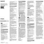
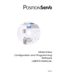
MCH Series Drives
Siemens P1 Communications Guide
About These Instructions
This documentation applies to the use of an MCH Series Variable Frequency Drive in a Siemens P1 Floor Level
Network (FLN) and should be used in conjunction with the MCH Series Installation and Operation Manual (Document
MH01) that shipped with the drive. These documents should be read in their entirety as they contain important
technical data and describe the installation and operation of the drive.
Siemens P1, System 600 and Apogee are trademarks of Siemens AG, Munich, Germany; http://w1.siemens.com.
In the United States: http://www.usa.siemens.com
© 2003 AC Technology Corporation
No part of this documentation may be copied or made available to third parties without the explicit written approval
of AC Technology Corporation. All information given in this documentation has been carefully selected and tested
for compliance with the hardware and software described. Nevertheless, discrepancies cannot be ruled out. AC
Tech does not accept any responsibility nor liability for damages that may occur. Any necessary corrections will be
implemented in subsequent editions.
Contents
1 Safety Information..............................................................................................................1
1.1
Warnings, Cautions and Notes...............................................................................1
1.1.1 General.....................................................................................................1
1.1.2 Application................................................................................................1
1.1.3 Installation................................................................................................1
1.1.4 Electrical Connection.................................................................................2
1.1.5 Operation..................................................................................................2
2 Introduction........................................................................................................................3
2.1
Floor Level Network Communications....................................................................3
2.2
Hardware Description............................................................................................3
2.3
Serial Communications Wiring...............................................................................3
3 Drive Setup and Programming............................................................................................4
3.1
Added Programming Parameters...........................................................................4
3.2
Omitted Parameters and Selections.......................................................................4
3.3
Modified Programming Parameters........................................................................5
3.4
Serial Communications Setup................................................................................5
4 MCH P1 Points...................................................................................................................7
4.1
MCH P1 Point Map.................................................................................................7
4.2
MCH P1 Point Descriptions....................................................................................8
4.3
Reference and Links..............................................................................................12
i
RG-MHSP1F
Safety Information
1
Safety Information
1.1
Warnings, Cautions and Notes
1.1.1 General
Some parts of Lenze controllers (frequency inverters, servo inverters, DC controllers) can be live, moving
and rotating. Some surfaces can be hot.
Non-authorized removal of the required cover, inappropriate use, and incorrect installation or operation
creates the risk of severe injury to personnel or damage to equipment.
All operations concerning transport, installation, and commissioning as well as maintenance must be
carried out by qualified, skilled personnel (IEC 364 and CENELEC HD 384 or DIN VDE 0100 and IEC report
664 or DIN VDE0110 and national regulations for the prevention of accidents must be observed).
According to this basic safety information, qualified skilled personnel are persons who are familiar with
the installation, assembly, commissioning, and operation of the product and who have the qualifications
necessary for their occupation.
1.1.2 Application
Drive controllers are components designed for installation in electrical systems or machinery. They are
not to be used as appliances. They are intended exclusively for professional and commercial purposes
according to EN 61000-3-2. The documentation includes information on compliance with EN 61000-3-2.
When installing the drive controllers in machines, commissioning (i.e. the starting of operation as directed)
is prohibited until it is proven that the machine complies with the regulations of the EC Directive 98/37/EC
(Machinery Directive); EN 60204 must be observed.
Commissioning (i.e. starting drive as directed) is only allowed when there is compliance to the EMC Directive
(89/336/EEC).
The drive controllers meet the requirements of the Low Voltage Directive 73/23/EEC. The harmonised
standards of the series EN 50178/DIN VDE 0160 apply to the controllers.
The availability of controllers is restricted according to EN 61800-3. These products can cause
radio interference in residential areas. In the case of radio interference, special measures may be
necessary for drive controllers.
1.1.3 Installation
Ensure proper handling and avoid excessive mechanical stress. Do not bend any components and do not
change any insulation distances during transport or handling. Do not touch any electronic components
and contacts. Controllers contain electrostatically sensitive components, which can easily be damaged by
inappropriate handling. Do not damage or destroy any electrical components since this might endanger
your health! When installing the drive ensure optimal airflow by observing all clearance distances in the
drive's user manual. Do not expose the drive to excessive: vibration, temperature, humidity, sunlight, dust,
pollutants, corrosive chemicals or other hazardous environments.
1
RG-MHSP1F
Safety Information
1.1.4 Electrical Connection
When working on live drive controllers, applicable national regulations for the prevention of accidents (e.g.
VBG 4) must be observed.
The electrical installation must be carried out in accordance with the appropriate regulations (e.g.
cable cross-sections, fuses, PE connection). Additional information can be obtained from the regulatory
documentation.
The regulatory documentation contains information about installation in compliance with EMC (shielding,
grounding, filters and cables). These notes must also be observed for CE-marked controllers.
The manufacturer of the system or machine is responsible for compliance with the required limit values
demanded by EMC legislation.
1.1.5 Operation
Systems including controllers must be equipped with additional monitoring and protection devices according
to the corresponding standards (e.g. technical equipment, regulations for prevention of accidents, etc.).
You are allowed to adapt the controller to your application as described in the documentation.
DANGER!
• After the controller has been disconnected from the supply voltage, do not touch the live
components and power connection until the capacitors have discharged. Please observe the
corresponding notes on the controller.
• Do not continuously cycle input power to the controller more than once every three minutes.
• Close all protective covers and doors during operation.
WARNING!
Network control permits automatic starting and stopping of the inverter drive. The system design
must incorporate adequate protection to prevent personnel from accessing moving equipment
while power is applied to the drive system.
Table 1: Pictographs used in these instructions
Pictograph
RG-MHSP1F
Signal word
Meaning
Consequences if ignored
DANGER!
Warning of Hazardous Electrical
Voltage.
Reference to an imminent danger that may
result in death or serious personal injury if the
corresponding measures are not taken.
WARNING!
Impending or possible danger
for persons
Death or injury
STOP!
Possible damage to equipment
Damage to drive system or its surroundings
NOTE
Useful tip: If observed, it will
make using the drive easier
2
Introduction
2
Introduction
This document will explain how to connect a Lenze-AC Tech MCH Variable Frequency Drive to a Siemens
P1 Floor Level Network (FLN). It is intended as a serial communications supplement only and will not
discuss normal drive operations. For more information regarding normal drive setup and functionality, refer
to the MCH Installation and Operation Manual (MH01).
2.1
Floor Level Network Communications
The Floor Level Network LAN is used to establish Direct Digital Control (DDC). A Field Cabinet directs all
activity on the FLN. The name Field Cabinet is a generic name for several products, including the Modular
Building Controller (MBC), Stand-alone Control Unit (SCU), LAN controller and the Apogee MBC.
The Field Cabinet maintains a Master & Slave relationship with the individual FLN devices. This means that
all communication on the FLN is initiated by the Field Cabinet (the Master) and a FLN device (a Slave) only
responds when it is issued a command.
The FLN utilizes the P1 Protocol, which is an asynchronous communication protocol. Communication is half
duplex, 8 data bits, no parity, 1 stop bit -- All data is transmitted LSB first. Handshaking is not implemented
for P1. The bit sequence is as follows:
DATA
START
1
2
3
4
5
6
7
8
STOP
CRC-16 Error Detection (transmitted MSB first) is used to ensure that messages are received correctly.
In the United States, Siemens currently uses two controller operating systems for Building Automation
Systems that use P1 for communication. One is Apogee. The other is System 600, also referred to as PreApogee. Lenze-AC Tech MCH Series P1 Drives have been tested and are compatible with both systems.
2.2
Hardware Description
The FLN Local Area Network port utilizes RS-485 compliant hardware. The FLN device is one of up to 32
nodes on the LAN. The communications rate is typically 4800 bps. However, on certain FLN devices, it may
also be 9600 bps.
2.3
Serial Communications Wiring
Figure 1 illustrates the MCH Series Terminal Strip and connections for a Siemens P1 FLN.
1
2
5A
5B
6
10A 10B
2
12A 13A 13B 13C 13D 14
15
2
RXA TXB 16
17
18
FLN +
FLN -
Earth
Ground
Figure 1: MCH Terminal Strip
Connect the FLN+ terminal to MCH terminal TXB.
Connect MCH terminal 2 to Earth Ground.
Connect the FLN- terminal to MCH terminal RXA.
Do NOT connect the FLN S (Shield) wire to the drive.
3
RG-MHSP1F
Drive Setup & Programming
3
Drive Setup and Programming
Most drive parameters (including those required for serial communications) are not accessible through the
FLN. They can only be accessed by entering the Programming Mode of the drive itself. Refer to the MCH
Installation and Operation Manual (MH01) for more information.
When in Programming Mode, the drive will not accept any write, memorize or characterize LAO commands
from the FLN. This is necessary to prevent conflicts between the two modes of parameter modification.
The parameter information in the MCH Installation and Operation Manual is based on Lenze-AC Tech’s
standard MCH Series ModbusTM Drive. There are some differences between the drive programming
parameters described in the manual and those that exist in the MCH Series P1 Drive.
3.1
3.2
Added Programming Parameters
59 SERIAL BAUDRATE
As stated previously the communications rate is typically 4800 bps but, on some
FLN devices, it may also be 9600 bps. This parameter, which has selections
of 4800 bps (default) and 9600 bps, has been added to accommodate both
possibilities.
60 SERIAL TIMEOUT
This parameter makes the serial watchdog timeout period selectable and is
described in detail in Section 3.4 Serial Communications Setup.
Omitted Parameters and Selections
36 SLEEP THRESHOLD
Sleep Mode functionality has not been added to the MCH Series P1 Drive so
these drive parameters do not exist.
37 SLEEP DELAY
38 SLEEP BANDWIDTH
41 ANALOG INPUT FILTER
52 TB14 OUT
53 TB15 OUT
54 RELAY
56 SERIAL LOSS
RG-MHSP1F
The following options have not been added to these parameters in the MCH
Series P1 drive:
INV MIN/MAX A
MIN ALARM
INV MIN ALARM
MAX ALARM
INV MAX ALARM
This parameter has not been added to the MCH Series P1 Drive. For a detailed
explanation of the action that is taken when serial communications with the
FLN are lost, refer to the description of Drive Parameter #60 (Serial Timeout)
in Section 3.4 Serial Communications Setup.
4
Drive Setup & Programming
3.3
3.4
Modified Programming Parameters
8 ACCEL and 9 DECEL
The largest value that can be transmitted using the P1 protocol is 32767. It
was therefore necessary to limit the maximum value for these parameters to
3000.0 seconds.
24 AUTO SOURCE
The default selection for this parameter has been changed to KEYPAD. Refer
to Section 3.4 Serial Communications Setup for more information.
32 HZ MULTIPLIER
The default setting for this parameter has been changed to 30.00. Refer to
Section 3.4 Serial Communications Setup for more information.
57 SERIAL
The default selection for this parameter has been changed to WITH TIMER to
provide limited “out-of-the-box” serial communication with the drive.
58 SERIAL ADDRESS
The minimum and maximum values for this parameter have been changed to
0 and 99, respectively, in accordance with the Siemens P1 Protocol Design
Specification. The default value has also been changed to 99. Refer to Section
3.4 Serial Communications Setup for more information
Serial Communications Setup
The factory default values for all drive parameters are setup to allow immediate serial communications
(without serial start and serial speed/setpoint commands). For serial speed/setpoint and/or serial start
control, modify the setting of Drive Parameter #30 (Control). The drive parameters that are required for
serial communications, including Drive Parameter #30, are described below.
24 AUTO SOURCE
must be set to KEYPAD for the drive speed/setpoint to be modified over the FLN.
30 CONTROL
should be set to accommodate the specific application intent:
NORMAL
Serial start and serial speed/setpoint commands are invalid.
NORM NO HAND
Same as NORMAL except the HAND/OFF/AUTO, herein
referred to as H/O/A, is limited to settings of OFF and AUTO.
SERIAL SPEED
Serial start commands are invalid. Serial speed/setpoint
commands are valid in AUTO H/O/A.
S SPD/NO HAND
Same as SERIAL SPEED except H/O/A is limited to settings of
OFF and AUTO.
SERIAL AUTO
Serial start and serial speed/setpoint commands are all valid
in AUTO H/O/A. This setting forces the drive to be started over
the FLN when in AUTO H/O/A.
S AUTO/NO HND
Same as SERIAL AUTO except H/O/A is limited to settings of
OFF and AUTO.
Serial STOP commands are accepted from the FLN regardless of the setting of Parameter 30.
5
RG-MHSP1F
Drive Setup & Programming
32 HZ MULTIPLIER
This parameter must be set for the specific application so that Actual Speed
(Point 5) and Command Speed (Point 10) will function properly. To calculate the
appropriate setting for this parameter, divide the Motor Rated Speed by Drive
Parameter #11 (Maximum Frequency). This parameter’s factory default setting of
30.00 assumes a motor rated speed of 1800 RPM.
57 SERIAL
This parameter needs to be set to either WITH TIMER (default) or W/O TIMER for
the drive to communicate with the FLN. Serial communications will not work if this
parameter is set to DISABLED.
58 SERIAL ADDRESS
This point contains the address of the FLN device. It is adjustable from 0−99 but
should be set in the range of 1-98 when on the LAN. This parameter’s default
address of 99 is intended for configuration purposes only.
59 SERIAL BAUDRATE This parameter defaults to 4800bps and will, typically, not have to be changed.
In some cases, however, the FLN may be set up to communicate exclusively with
VFDs. In this situation, a baudrate of 9600bps is preferred and this parameter
should be set accordingly.
60 SERIAL TIMEOUT
This parameter makes the serial watchdog timeout period selectable. This
parameter has a minimum value of 10 seconds and a maximum value of 255
seconds. The default is 30 seconds. If no action is to be taken when a serial
watchdog timeout occurs, Drive Parameter #57 (Serial) should be set to W/O
TIMER. This will disable the watchdog timer. Otherwise Drive Parameter #57
(Serial) should be set to WITH TIMER.
If the FLN has started the drive or has modified the Speed Source Selection (Point
34), the Keypad Speed Command (Point 36) or the Keypad Setpoint Command
(Point 37) and a serial watchdog timeout occurs, the drive will be taken out of
serial control. If the drive was running when the timeout occurred, the drive will
also stop the motor by tripping into a SERIAL FAULT. A fault reset command, issued
via Clear Present Fault (Point 94), a keypad stop or a terminal stop is required to
clear the fault.
When Drive Parameter #30 (Control) is set to SERIAL SPEED the speed reference
being used MUST be set to the drive keypad (-KEY or -MKB) for the serial watchdog
to be active. When Drive Parameter #30 is set to SERIAL AUTO the serial watchdog
will be active with any speed reference.
When a serial timeout occurs and the drive is taken out of serial control, any
overrides that were in effect prior to the timeout will be maintained. In order for the
drive keypad to take control of the Speed Source Selection, the Keypad Command
Speed or the Keypad Setpoint Command, the drive H/O/A must first be toggled to
HAND or OFF to release the overrides on the corresponding P1 points.
RG-MHSP1F
6
P1 Points
4
MCH P1 Points
Any sub-point that can be commanded is an OUTPUT (LDO or LAO). Any sub-point that cannot be commanded
is an INPUT (LDI or LAI).
When an LAO point is unbundled (or characterized), the initial value used to unbundle it must be within
the defined boundaries of the point. For example: the initial value for Point #36 (KEY SPD CMD) must be
defined as follows:
Drive Parameter #10 (Minimum Freq) <= Initial Value <= Drive Parameter #11 (Maximum Freq).
If an invalid initial value is used, the unbundled point will always report a FAIL status. This point must be
removed and re-characterized with a valid initial value.
4.1
MCH P1 Point Map
Table 2: Siemens P1® Point Map for MCH Series Drives
Point
#
Point
Type
Description (P1 Point Name)
ENG/SI
Units
ENG/SI
Slope
ENG/SI
Intercept
ENG/SI On
Text
ENG/SI Off
Text
Default
Value
01
LAO
Serial Address (CTRL ADDRESS)
--
1.00
0
--
--
99
02
LAI
Application Number (APPLICATION)
--
1.00
0
--
--
2726
[03]
LAI
Actual Frequency (OUTPUT FREQ)
HZ
0.01
0
--
--
0
[04]
LAI
Actual Percent Output (OUTPUT PCT)
PCT
1.00
0
--
--
0
[05]
LAI
Actual Speed (OUTPUT SPEED)
RPM
1.00
0
--
--
0
[07]
LAI
Load Percent (LOAD PERCENT)
PCT
1.00
0
--
--
0
[08]
LAI
Command Frequency (COMMAND FREQ)
HZ
0.01
0
--
--
2000
[09]
LAI
Command Percent Output (COMMAND PCT)
PCT
1.00
0
--
--
33
[10]
LAI
Command Speed (COMMAND SPD)
RPM
1.00
0
--
--
600
11
LAI
Software Version (SOFTWARE VER)
--
1.00
0
--
--
Varies
[12]
LAI
Total Runtime (RUNTIME HRS)
HRS
1.00
0
--
--
0
[13]
LAI
DC Bus Voltage (DC BUS VOLTS)
PCT
1.00
0
--
--
0
[14]
LAI
Operational Status (RUN STATUS)
--
1.00
0
--
--
3
[15]
LAI
H/O/A Mode (HOA MODE)
--
1.00
0
--
--
0
16
LDI
PID Mode (PID MODE)
--
1.00
--
ENABLE
DISABL
0
[17]
LAI
PID Setpoint Command (PID SETPOINT)
--
1.00
0
--
--
16368
[18]
LAI
PID Feedback (PID FEEDBACK)
--
1.00
0
--
--
0
20
LAO
Day/Night Override Time (OVRD TIME)
HRS
1.00
0
--
--
1
[21]
LDI
Current Direction (FWD.REV)
--
1.00
--
REV
FWD
0
[23]
LDI
Run/Stop Status (RUN.STOP)
--
1.00
--
RUN
STOP
0
[24]
LDO
Start/Stop Drive (CMD RUN.STOP)
--
1.00
--
RUN
STOP
0
[29]
LDO
Day/Night Operation (DAY.NIGHT)
--
1.00
--
NIGHT
DAY
0
31
LAO
Acceleration Rate (ACCEL RATE)
SEC
0.10
0
--
--
300
32
LAO
Deceleration Rate (DECEL RATE)
SEC
0.10
0
--
--
300
[34]
LAO
Speed Source Selection (SOURCE SEL)
--
1.00
0
--
--
0
[36]
LAO
Keypad Speed Command (KEY SPD CMD)
HZ
0.01
0
--
--
2000
[37]
LAO
Keypad Setpoint Command (KEY STPT CMD)
--
1.00
0
--
--
16368
[40]
LDI
TB-14 / Relay #2 (TB14.RELAY2)
--
1.00
--
ON
OFF
0
7
RG-MHSP1F
P1 Points
Point
#
Point
Type
Description (P1 Point Name)
ENG/SI
Units
ENG/SI
Slope
ENG/SI
Intercept
ENG/SI On
Text
ENG/SI Off
Text
Default
Value
[41]
LDI
TB-15 / Relay #3 (TB15.RELAY3)
--
1.00
--
ON
OFF
0
[42]
LDI
Relay #1 (RELAY1)
--
1.00
--
ON
OFF
0
[92]
LAI
Present Fault (FAULT)
--
1.00
0
--
--
0
[93]
LDI
Fault Condition (OK.FAULT)
--
1.00
--
FAULT
OK
0
[94]
LDO
Clear Present Fault (CLEAR FAULT)
--
1.00
--
RESET
NORMAL
0
99
LAI
Error Status Flags (ERROR STATUS)
--
1.00
0
--
--
0
NOTES:
1. Point numbers that appear in brackets [ ] may be unbundled at the field panel.
2. Point Types: LDI = Logical Digital Input, LDO = Logical Digital Output,
LAI = Logical Analog Input, LAO = Logical Analog Output
4.2
MCH P1 Point Descriptions
Point 1:
This point reflects the serial address of the drive. As stated earlier, this point is selectable up
to 99 but should only be set in the range of 1-98 when on the LAN.
Point 2:
This point contains the number of the current application. Since this point currently only has
one value, that being 2726, this point is not capable of being commanded.
Point 3:
This point is for monitoring the actual speed of the drive in Hz.
Point 4:
This point is for monitoring the actual speed of the drive as a percentage of the value set in
Drive Parameter #11 (Maximum Freq). It is rounded to the nearest whole number.
Point 5:
This point is for monitoring the actual speed of the drive in RPMs. The value returned by this
point is the actual drive speed in Hz multiplied by the value set in Drive Parameter #32 (Hz
Multiplier) and rounded to the nearest whole number.
Point 7:
This point is for monitoring the drive’s load current as a % of rated current.
Point 8:
This point is for monitoring the commanded drive speed in Hz.
Point 9:
This point is for monitoring the commanded drive speed as a percentage of the value set in
Drive Parameter #11 (Maximum Freq). It is rounded to the nearest whole number.
Point 10: This point is for monitoring the commanded drive speed in RPMs. The value returned by this
point is the commanded drive speed in Hz multiplied by the value set in Drive Parameter #32
(Hz Multiplier) and rounded to the nearest whole number.
Point 11: This point returns the software version (including the current revision) of the drive firmware.
This information can also be obtained from Drive Parameter #63 (Software Version). For
example, drive software version MC09803 will be displayed as 9803.
Point 12: This point is for monitoring the number of hours that the drive has been running since its first
power-up.
RG-MHSP1F
8
P1 Points
Point 13: This point is for monitoring the drives DC Bus Voltage as a percentage of nominal DC bus
voltage.
Point 14: This point is for monitoring the actual operating condition of the drive. The value returned is a
number between 0 and 10 which corresponds to one of the following operating states:
VALUE
OPERATIONAL STATE
0
FAULT LOCKOUT
1
FAULT
2
START PENDING
3
STOP
4
DC BRAKE
5
RUN AT 0Hz
6
RUN
7
ACCEL
8
DECEL
9
CURRENT LIMIT
10
DECEL OVERRIDE
Point 15: This point is for monitoring the drive H/O/A status. If the drive H/O/A is OFF, this point will
return 0 and serial speed/setpoint and serial start commands will not be accepted from the
FLN. If the drive H/O/A is HAND, this point will return 1 and serial speed/setpoint and serial
start commands will not be accepted from the FLN. If the drive H/O/A is AUTO, this point will
return 2 and, depending on the setting of Drive Parameter #30 (Control), serial speed/setpoint
and serial start commands will be accepted from the FLN. For more information, refer to
Section 3.4 Serial Communications Setup.
Point 16: This point is for monitoring the general state of the drive’s PID mode. If Drive Parameter #70
(PID Mode) is set to OFF this point returns DISABLED. If Drive Parameter #70 is set to either
NORMAL or REVERSE, then this point returns ENABLED.
Point 17: This point is for monitoring the commanded PID Setpoint and is displayed in the drive’s internal
PID units with a range of 0-32736. A value of 0 represents the lower of Drive Parameter #75
(Feedback @ Min) and Drive Parameter #76 (Feedback @ Max). A value of 32736 represents
the higher of Drive Parameter #75 (Feedback @ Min) and Drive Parameter #76 (Feedback @
Max).
If the user wishes to view this point in other than internal units, the point can be rescaled with
different slope and intercept values during characterization. The new intercept value should
be the minimum value of the desired display range. The new slope should be calculated by
dividing the desired display range by 32736. For example, a display range of –100 PSI to +100
PSI would require an intercept value of –100 and a slope of (200/32736=) 0.0061095.
9
RG-MHSP1F
P1 Points
Point 18: This point is for monitoring the current PID Feedback value at the input specified by Drive
Parameter #74 (PID Feedback). This point is displayed in the drive’s internal PID units with a
range of 0-32736. A value of 0 represents the lower of Drive Parameter #75 (Feedback @ Min)
and Drive Parameter #76 (Feedback @ Max). A value of 32736 represents the higher of Drive
Parameter #75 (Feedback @ Min) and Drive Parameter #76 (Feedback @ Max).
If the user wishes to view this point in other than internal units, the point can be rescaled with
different slope and intercept values during characterization. The new intercept value should
be the minimum value of the desired display range. The new slope should be calculated by
dividing the desired display range by 32736. For example, a display range of –100 PSI to +100
PSI would require an intercept value of –100 and a slope of (200/32736=) 0.0061095.
Point 20: This point contains the override time in hours. This value will be available for reading and
writing by the FLN but has no purpose in the MCH Series P1 drive.
Point 21: This point indicates the direction in which the drive is currently running.
Point 23: This point indicates whether or not the drive is currently running.
Point 24: This point reflects the last serial START(RUN)/STOP command that was issued to the drive.
Point 29: This point contains the current occupancy mode of the application. This value will be available
for reading and writing by the FLN but has no purpose in the MCH Series P1 drive.
Point 31: This point sets the time that it will take for the drive to ramp up the motor from 0.00Hz to
the value set in Drive Parameter #18 (Base Frequency). The maximum value for this point is
3000.0 seconds. The minimum value is either 0.1 seconds or 0.3 seconds depending on the
horsepower of the drive. For the actual minimum boundary, refer to the MCH Installation and
Operation Manual.
Point 32: This point sets the time that it will take for the drive to ramp down the motor from the value
set in Drive Parameter #18 (Base Frequency) to 0.00Hz. The maximum value for this point is
3000.0 seconds. The minimum value is between 0.1 seconds and 2.0 seconds depending on
the voltage rating and horsepower of the drive as well as the presence of a dynamic brake. For
the actual minimum boundary, refer to the MCH Installation and Operation Manual.
Point 34: This point mimics the functionality of the SPEED SOURCE key on the drive keypad. It is used
to determine whether the drive will get its speed/setpoint reference from Drive Parameter #24
(Auto Source) or Drive Parameter #29 (Hand Source). A value of 0 corresponds to NORMAL. A
value of 1 corresponds to HAND ONLY. A value of 2 corresponds to AUTO ONLY.
For more information refer to Section 14.2.4 Speed Source Selection of the MCH Installation
and Operation Manual.
This point allows the user to toggle between OPEN loop speed control and CLOSED loop PID
control when PID mode (Point 16) is ENABLED. The ability to command this point through the
FLN is dictated by the setting of Drive Parameter #30 (Control) and the drive’s current H/O/A
Mode (Point 15).
RG-MHSP1F
10
P1 Points
Point 36: This point monitors and controls the Keypad Speed Command. The ability to command this
point through the FLN is dictated by the setting of Drive Parameter #30 (Control) and the drive’s
current H/O/A Mode (Point 15).
Point 37: This point monitors and controls the Keypad Setpoint Command. The ability to command this
point through the FLN is dictated by the setting of Drive Parameter #30 (Control) and the drive’s
current H/O/A Mode (Point 15).
This point is displayed in the drive’s internal PID units with a range of 0-32736. A value of
0 represents the lower of Drive Parameter #75 (Feedback @ Min) and Drive Parameter #76
(Feedback @ Max). A value of 32736 represents the higher of Drive Parameter #75 (Feedback
@ Min) and Drive Parameter #76 (Feedback @ Max).
If the user wishes to view this point in other than internal units, the point can be rescaled with
different slope and intercept values during characterization. The new intercept value should
be the minimum value of the desired display range. The new slope should be calculated by
dividing the desired display range by 32736. For example, a display range of –100 PSI to +100
PSI would require an intercept value of –100 and a slope of (200/32736=) 0.0061095.
Point 40: This point monitors the state of the drive’s TB-14 or Relay #2 output. This point can be used to
indicate various drive conditions as specified by Drive Parameter #52 (TB14/Relay #2). Refer
to the MCH Installation and Operation Manual for more information.
Point 41: This point monitors the state of the drive’s TB-15 or Relay #3 output. This point can be used to
indicate various drive conditions as specified by Drive Parameter #53 (TB15/Relay #3). Refer
to the MCH Installation and Operation Manual for more information.
Point 42: This point monitors the state of the drive’s Relay #1 output. This point can be used to indicate
various drive conditions as specified by Drive Parameter #54 (Relay #1). Refer to the MCH
Installation and Operation Manual for more information.
11
RG-MHSP1F
P1 Points
Point 92: This point indicates the type of fault on which the drive is currently tripped. This point returns
a value between 0 and 24 which corresponds to one of the following fault conditions:
VALUE
0
1
2
3
4
5
6
7
8
9
10
11
12
FAULT
NO FAULT
OUTPUT FAULT
E-STOP
HIGH DC BUS VOLTS
HIGH DRIVE TEMPERATURE
THERMAL OVERLOAD
OUTPUT FAULT
LOW DC BUS VOLTS
START ERROR
DC BRAKE ERROR
FOLLOWER LOSS
DB ERROR
POWER SAG
VALUE
13
14
15
16
17
18
19
20
21
22
23
24
FAULT
CONTROL FAULT
LANGUAGE
EXTERNAL FAULT
INTERNAL16
POWER TRANSIENT
S/W ERROR #1
S/W ERROR #2
S/W ERROR #3
S/W ERROR #4
S/W ERROR #5
GENERAL S/W ERROR
SERIAL COMMUNICATION LOSS
Point 93: This point indicates whether or not the drive is currently tripped on a fault. This point returns
OK (0) if the drive is not in a fault condition or FAULT (1) if it is.
Point 94: This point is used to clear the current fault through the FLN. Set this point to RESET (1) to clear
the present fault. Once the fault has been cleared, the value of this point will automatically
return to NORMAL (0).
Point 99: This point is not used by the MCH Series P1 drive and is, therefore, not capable of being
commanded. When read, this point will always return a value of 0.
4.3
Reference and Links
MCH Series Variable Frequency Drives visit:
http://www.lenze-actech.com
Siemens Building Technologies visit:
http://www.buildingtechnologies.usa.siemens.com/
The APOGEE Building Automation System visit:
http://www.buildingtechnologies.usa.siemens.com/Products__and__Systems/Building_
automation_and_control/APOGEE_Building_Automation_System/Overview/standard_
protocols.htm
RG-MHSP1F
12
AC Technology Corporation
630 Douglas Street • Uxbridge MA 01569 • USA
Sales: 800-217-9100 •Service: 508-278-9100
www.lenze-actech.com
RG-MHSP1-e4