1
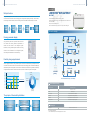
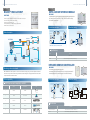
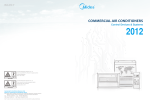
47
R410A DC Inverter Individual V4 PLus 50Hz
R410A DC Inverter Individual V4 PLus 50Hz
Control Systems
Building Management System
Midea Router
Centralized Control
Individual control
Network Monitoring
Controller
485A-I
Wire controller
KJR-10B
KJR-12B
MD-NIM01
KJR-90A
Remote controller
Midea Remote
Service Centre
User’s Monitoring
System
RM02
RM05
R05
R06
R51
R71
Weekly Schedule
Centralized Controller
Connectable to
various sized BMS/BAS
MD-CCM09
Accessories
Card-key Interface
Indoor Centralized
Controller
MD-NIM05
MD-CCM03
MD-CCM07
Outdoor Centralized
Controller
Card-key
Infared Sensor
MD-CCM02
Web Monitoring Tool
MD-CCM08
Note: The wires in the diagram show the signal flows only,
while not represent the actual connecting ways.
*Combined ON/OFF function can be customized from us.
MD-NIM09
MD-CCM08
Combined ON/OFF*
INFARED SENSOR
Outdoor units
48
49
R410A DC Inverter Individual V4 PLus 50Hz
R410A DC Inverter Individual V4 PLus 50Hz
Wireless Remote Controller
Comparison of Controllers
Item
Remote
Model name
RM05
R06
R05
R51
1
MAX. controllable IDU
Centralized
Controller
3rd-generation
Monitoring System
KJR-10B
KJR-12B
KJR-90A
MD-CCM03
MD-CCM09
KJR-90B
KJRF-180A
MDV-WLJKXT
1
16/64
1024
Wired Controller
On/Off
Operation mode setting
Heating mode
Fan speed setting
AC control
function
RM02
RM05
R05
R06
R51
R71
Functions
Portable device
Explicit user interface
Wireless remote controller is a portable control
device. It provides a convenient way for users to
control the AC everywhere within a range up to
11m.
Users can synchronize the air conditioners’
parameters with the display panel of the wireless
remote controller. It’s the very way to make the room
environment precisely work at the user’s will.
Room temp. setting
Vertical swing
Temp
1
Transmitting display
2
Running mode
Horizontal swing
Economic mode
Group setting
ON
Key lock
3
ON/OFF
5
Time
6
Lock
4
Economic operation
OFF
8
7
Time ON/OFF
9
Fan speed
Backlight
Background light
Current time
Display
RC prohibition
Background light allows user operate the device in
the dark room freely. The device lights whenever
the keys are pressed and last during the whole
operating procedure.
Address
Error code
Period
Timer
On/Off per day
/4
On/Off per week
Built-in timer
/28
Built-in daily timer offers the convenience of
automatically starting and turning down the air
conditioners according to the set time.
On/Off timer
FOLLOW ME
Emergent stop
Control
/Week
Emergent start
Address setting
24°C
ON
0
Addressing setting
3
6
9
12
15
OFF
18
21 Time
The inddor unit is set to work at automode from 8:00 to 20:00
Besides the machine’s auto assigning addresses
function, users can set the indoor unit’s address via
the wireless remote controller.
BMS access
Control via internet
: Each of this kind of controller has the corresponding functions.
: This function is optional.
: This function is not available through the corresponding controller.
Specifications
Model
Dimensions
Power
RM02
RM05
R05
R06
R51
R71
150×60×15
150×65×20
150×65×20
100×55×20
140×60×15
125×42×27
1.5V(LR03/AAA)×2
50
51
R410A DC Inverter Individual V4 PLus 50Hz
R410A DC Inverter Individual V4 PLus 50Hz
Centralized Controller
Wired Controller
INDOOR CENTRALIZED CONTROLLER
MD-CCM03
KJR-10B
KJR-12B
KJR-90A
Functions
Functions
Follow me
Centralized control
Three lock modes
MD-CCM03 is a multifunctional device which is
able to control up to 64 indoor units. And the
connection length can be up to 1,200m. With the
newly designed machines, this device connects to
the master outdoor unit, making the centralized
wiring quite simple.The 2 ways of connecting is as
follows:
Centralized controller MD-CCM03 provides a
superior way to manage the indoor units. Users are
able to make their own choice from locking the
wireless controller, locking the running mode or lock
the MD-CCM03’s keyboard, as they wish.
With the FOLLOW ME function, the wired controller
can detect the air temperature at the user’s altitude
Sensor part
instead that of the ceiling or the floor. This helps
making the room environment comfortable and the
temperature accurate.
FOLLOW ME Button
X,Y,E
P,Q,E
X,Y,E
Built-in timer
P,Q,E
X,Y,E
P,Q,E
X,Y,E
Locking
Locking
Locking
Centralized
Running
Remote
Keyboard
Controller
Mode
Controller
X,Y,E
Single/unified control mode
Built-in daily timer offers the convenience of
automatically starting and turning down the air
conditioners according to the set time.
24°C
ON
0
3
6
9
12
15
OFF
18
21 Time
The inddor unit is set to work at automode from 8:00 to 20:00
Easy connection
Easy installation
Wired controller conveniently connects to the indoor
unit’s display panel with the appropriative connecting
wire.
The wired controller allows to be installed into the
wall by fixing the bottom directly or fixing the device to
a mounting cabinet.
Indoor unit working status display
MD-CCM03 displays both the indoor units working
status and the error codes. Via checking the error
codes table in the user manual, users can easily
find out the malfunction and call the repairman.
Error code or
protection code
The control object can be either single or all, making
the controlling operation convenient and easy. With
the operation signal feedback, users ensure their
machines work at the precise working mode.
OPR.UNSUCCESS
Connecting
status matrix
#
ERROR
INLINE ON OFF PROTECT
MODE
AUTO
01 02 03 04 05 06 07 08 09 10 11 12 13 14 15 16
(1.6)
GROUP QUERY RUN SET
#GROUPALL
00+
16+
ROOM.TEMP
Display panel
T3
KJR-10B
Wire controller
Hr ON
OFF
T2A
T2B
SET.TEMP
32+
FAN
Hr
48+
OPR.UNSUCCESS
Access to network monitoring
MD-CCM03 is able to bridge up to 64 indoor units to the network monitoring system and the building
management system.
Indoor main board
MAX.64
MD-CCM03
Specifications
Model
Dimensions
Power
Specifications
10B
120×120×15
12B
90A
120×120×15
90×86×13
Power from the display panel. Extra power is unnecessary.
Model
Dimensions(H×W×D)(mm)
Power
MD-CCM03
170×110×70
198-242V(50/60Hz)
52
53
R410A DC Inverter Individual V4 PLus 50Hz
R410A DC Inverter Individual V4 PLus 50Hz
Centralized Controller
Centralized Controller
WEEKLY SCHEDULE CENTRALIZED
CONTROLLER
WIRED CONTROLLER
KJRF-180A
MD-CCM09
Newly designed centralized controller controls up to 16
indoor units and 1 heat pump water heater in addition.
Functions
Functions
Weekly schedule
MD-CCM09 allows up to 64 indoor units making the
weekly schedule. Users can set up to 4 periods per
day and select the desired running mode and room
temperature. The operating object could be any
indoor unit or all the indoor units.
8:00
16:00
23:59
Sun
28°C
22°C
Mon
26°C
22°C
17°C
23°C
Tue
26°C
22°C
17°C
23°C
Wed
26°C
22°C
17°C
23°C
Thu
26°C
22°C
26°C
Fri
26°C
22°C
26°C
Sat
28°C
off
24°C
24°C
Multiple machine control
Single/unified control
KJRF-180A is a multiple functions device, which can
control both indoor air conditioners and heat pump
water heater. Moreover, KJRF-180A is able to
connect to the fresh air unit and realize the operation.
KJRF-180A provides an easy way to control the
indoor unit and water heater. User can quickly choose
the water heater or the fresh air unit to adjust their
running modes.
KJRF-180A
Three lock modes
Single/unified control mode
Centralized controller MD-CCM03 provides a
superior way to manage the indoor units. Users are
able to make their own choice from locking the
wireless controller, locking the running mode or lock
the MD-CCM03’s keyboard, as they wish.
The control object can be either single or all, making
the controlling operation convenient and easy. With
the operation signal feedback, users ensure their
machines work at the precise working mode.
KJRF-180A
Fresh air
Wall Mounted Unit
Wall Mounted Unit
Wall Mounted Unit
Fresh air
Water Heater
Wall Mounted Unit
Water Heater
OPR.UNSUCCESS
Locking
Locking
Locking
Centralized
Running
Remote
Keyboard
Controller
Mode
Controller
Graceful design
Easy installation
KJRF-180A is designed with graceful appearance,
especially suitable for the high class environment.
The key lock function helps avoiding unnecessary
operation by mistake.
KJRF-180A offers two different appearances to
mostly suit the installation. Both of them are easy to
operate.
Indoor unit working status display
Error code or
protection code
Connecting
status matrix
GROUP QUERY RUN SET
#GROUPALL
#
ERROR
INLINE ON OFF PROTECT
MODE
AUTO
01 02 03 04 05 06 07 08 09 10 11 12 13 14 15 16
(1.6)
MD-CCM03 displays both the indoor units working
status and the error codes. Via checking the error
codes table in the user manual, users can easily find
out the malfunction and call the repairman.
00+
16+
ROOM.TEMP
T3
Hr ON
Specifications
OFF
T2A
T2B
SET.TEMP
32+
FAN
Hr
48+
OPR.UNSUCCESS
Specifications
Model
MD-NIM09
Model
KJRF-180A
Dimensions(H×W×D)(mm)
170×110×70
Dimensions(H×W×D)(mm)
180×122×69
Power
198-242V(50/60Hz)
Power
220V(50/60Hz)
54
55
R410A DC Inverter Individual V4 PLus 50Hz
R410A DC Inverter Individual V4 PLus 50Hz
Centralized Controller
Central Control Software
UNIFIED ON/OFF CONTROLLER
3RD GENERATION
MONITORING SYSTEM
KJR-90B
Unified controller designed with graceful appearance and explicit panel.
Functions
Functions
Unified control
Friendly user interface
KJR-90B only offers the on/off and heating/cooling
choice for the indoor unit. And the running temperature
is set to be comfortable previously. By this way, the
indoor environment is quite convenient to manage.
3rd generation monitoring system offers a simple and explicit user interface to allow realize its functions
simply.3rd generations monitoring system is able to control up 1024 indoor units and 512 outdoor units.
28°C
20°C
cooling
heating
Group definition 3rd
Centralized control
KJR-90B centralized control up to 16 indoor units.
Max.16
The structure of the building
Light indicator
The lights of the KJR-90B indicate the indoor unit’s running mode. This helps discovering the abnormal indoor
unit. After the operations, the lights will fade to save energy and avoid disturbance. The indications are as
follows:
Light
Single On/Off key
Blue
Red
Cooling/Fan
Heating
IDU Error
EEPROM Error
Unified On/Off key
Easy installation
KJR-90B can be easily mounted on the built-in cabinet:
Specifications
Model
KJR-90B
Dimensions(H×W×D)(mm)
90×86×8
Power
Flash
Powered from display panel. Extra power unnecessary.
The layout drawing of the
floor makes it easy to select
the desired unit.
Click the unit to operate
56
57
R410A DC Inverter Individual V4 PLus 50Hz
R410A DC Inverter Individual V4 PLus 50Hz
Accessories
LONWORKS® BMS GATEWAY
Multiple functions
3rd generation system is able to realize the remote control of indoor units. The command of indoor unit
can be both the normal ones, such as changing the running modes, adjusting the temp., timer functions,
and the higher class command, such as excluding the other controllers to realize unique PC control.
Normal
Group
Unique
Funtions
Settings
PC Control
Running
3rd generation
status
monitoring
Reports
system
MD-CCM07
Cooperate with the 3rd generation monitoring software.
Enables centralized control of up to 1024 indoor units and 512 outdoor units to
the LonWorks BMS.
Easily connects to the BMS system.
Ideal for scattered units of large projects, such as high office buildings, etc.
Network example
Running parameter display
3rd generation system can synchronize both the indoor
and outdoor units’ running status and parameters, to
UPS
realize the visual control of the refrigerant system.
Indoor side
Moreover, the 3rd generation system records the running
status and error information of the refrigerant system,
which helps the maintenance accurate and easy.
Electricity charge apportionment
With the appropriate devices, 3rd generation system can record the total electricity consumption and the
on/off time of the outdoor units. And with the indoor units’ actual cooling power, the software intelligently
distributes the power consumption to each indoor unit. Moreover, the software can generate the electricity
charge bills and the bill of the indoor units’ on/off time, which is a basis of the power consumption.
Actual Usage Rate
0%
35%
35.3%
35% 35.1%
Displayed Rate
20%
20%
10%
MD-CCMO7
gateway
Room01
(60kWh)
40%
30%
Outdoor side
power distribution
UPS is recommended only, not necessary.
Room04
(210kWh)
Room02
(120kWh)
19.4%
Recommended config
10.2% 10.2%
Room01
Room02
Room03
Room04
Room03
(210kWh)
Operating system
WIN2000/WIN XP SP4
CPU
Pentium 4 2G or above
HDD
40G free space
Interface port
The principle of the electricity distribution
Software
3rd generation monitoring software kit
Database
Microsoft SQL Sever 2000 personal edition
Electricity meter
Room 01 electric power
consumption
Demand capacity
of Room01
Total demand capacity
of indoor units
Total power
consumption
2 RS-232 terminals and 3 USB ports
Chint DTS634 or corresponding model
Packing list
Packing list
PC should be field supplied.
3-core shield twisted pair lines should be applied to the network.
MD-CCM07 and power converter
58
59
R410A DC Inverter Individual V4 PLus 50Hz
R410A DC Inverter Individual V4 PLus 50Hz
Accessories
Accessories
BACNET® BMS GATEWAY
HOTEL CARD KEY INTERFACE MODULE
MD-NIM05
MD-CCM08
Cooperate with the wired controller to realized humanistic automatic control.
High voltage power is unnecessary, making the device safe and steady.
Auto-restart function inside.
Contains 4 groups of RS-485 communication ports and be able to connect up to
256 indoor units or 128 outdoor units to the BMS.
Be free to connect to the BMS or not.
Be compatible with 3rd generation monitoring software Firebird.
Monitor machines via local network.
Installation example
Network example
Electrical wiring
KJR-10B
KJR-10B
Outdoor units
MD-CCM08
MD-NIM05
MD-NIM05
Indoor units
CCM02
Outdoor units
Model
BACnet/IP protocol
Indoor units
BMS
86×72.8×15.5
Power
Powered from display panel. Extra power unnecessary.
MD-NIM09
MD-CCM08 allows users explore the units via local network, simply using the Internet Explorer. Moreover,
users can not only check the units running conditions, but also change the running parameter of the units, which
is quite convenient for users to control.
Wide compatibility
Automatically adjust the room environment.
Automatically extend the shutting down time, avoiding frequent ON/OFF.
Graceful appearance accommodates itself to the different buildings.
Installation example
Electrical wiring
CCM08 has a wonderful adaptability to the BMS.
SIMENS
BMS software
APOGEE
Infra-red inductive controller
Brand
KJR-10B
TRANE
KJR-10B
KJR-10B
Wire controller
Infra-red
sensor
APOGEE
A N Y W
Display panel
CN3
H E R E
MD-NIM09
TM
2
MD-NIM09/E
MD-NIM09
CN2
CN1
S1
Infra-red inductive
control box
Tracer Summit
TRACER SUMMT
MD-NIM09 works together with the wired controller.
3
Honeywell
Alerton
4
Schneider
Andover
Optional accessories
Specifications
Model
5
Johnson
1
INFRARED SENSOR CONTROLLER
Monitoring units via local web
1
2
MD-NIM05
Dimensions(H×W×D)(mm)
Company
CN
Optional accessories
Specifications
HUB
CCM03
CN
AC contactor
Wired controller is necessary in this card-key system.
RS485
Monitoring
system
KM
Card key
Card key
CCM03
TCP/IP
220V
METASYS
Dimensions(H×W×D)(mm)
Power
MD-NIM09
Senor part: 46×30×25.6, Control box: 86×72.8×15.5
Powered from display panel. Extra power unnecessary.
Indoor main board
60
61
R410A DC Inverter Individual V4 PLus 50Hz
R410A DC Inverter Individual V4 PLus 50Hz
Accessories
3-PHASE PROTECTOR
Selection software
GMR-32B
Detect the power condition and make the corresponding protecting action.
Protect the compressor from being damaged.
Automatically distinguish the power supply’s abnormal type and automatically recover.
Midea has developed a new program to design V4+i
systems
Excellent reliability
which
meets
the
consultants’
and
distributors’ requirements. The software provides a
quick and convenient selection for users, which
The protector protects the entire system from power supply problems, Moreover, the protector can
automatically recover from switching off status.
supports multi-languages. Greatly improving the
selection efficiency and simplifying the procedure.
Multiple protections
GMR-32B protects the entire system from many kinds of power supply problems.
Protection
Type
Action Time
Phase reverse
0.5S
Dynamic/static phase loss
Over/under voltage
Action condition
1S
-
7S
T
30S
Phase imbalance
Operating voltage is over setting voltage
Voltage deviation is over 10%
5S
Fail-safe
Input power fails, relay does not act
Specifications
Model
GMR-32B
Dimensions(H×W×D)(mm)
63×43×79
Power
DTS634/DTS636
Calculate the power consumption.
Do not need adjustment after working for long periods.
One outdoor unit corresponds one digital power meter.
Indications and installation
15mm long crack
72
LCD
A phase
B phase
C phase
201
Impulse
230
The digital power meter works at low
consumption. The working power is as
follows:
Voltage circuit: less than 2W/10VA
Current circuit: less than 2.5VA
131
145
Optional accessories
Specifications
Model
Dimensions(H×W×D)(mm)
Power
Load calculation
It contains project information such as project name,
nation, location, etc. Detailed meteorologic datas
make the machines selected fit for the local
environment well.
It provides two calculation methods. Directly decide
the room load or input the detailed parameters such
as room area, estimated cooling/heating load index,
heating capacity and cooling capacity.
A/C selection
Piping drawing
There are 13 types and 84 models of indoor units and
9 models of outdoor units for choosing.
Piping drawing shows the detailed layout of an A/C
system and parameters of piping and branch
distributors.
Controller selection
Report output
To select the right central controller for indoor units
and outdoor units; wireless or remote controller for
indoor units.
Output a total report of selection project in word or
excel format.
200-500V(50/60Hz)
DIGITAL POWER METER
Low power consumption
Project
DTS634/DTS636
230×145×72
200V-500V(50Hz)
The digital power meter is
checked to be up to standard
after it is manufactured, so it's
able to work at once on the
project site. The lights
indications and the installation
are as the left.
62