1
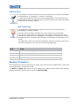
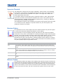
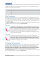
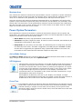
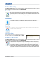
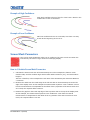
Interactivity Kit Setup Guide 020-100997-03 NOTICES COPYRIGHT AND TRADEMARKS Copyright ©2014 Christie Digital Systems USA Inc. All rights reserved. All brand names and product names are trademarks, registered trademarks or trade names of their respective holders. GENERAL Every effort has been made to ensure accuracy, however in some cases changes in the products or availability could occur which may not be reflected in this document. Christie reserves the right to make changes to specifications at any time without notice. Performance specifications are typical, but may vary depending on conditions beyond Christie's control such as maintenance of the product in proper working conditions. Performance specifications are based on information available at the time of printing. Christie makes no warranty of any kind with regard to this material, including, but not limited to, implied warranties of fitness for a particular purpose. Christie will not be liable for errors contained herein or for incidental or consequential damages in connection with the performance or use of this material. Canadian manufacturing facility is ISO 9001 and 14001 certified. WARRANTY Products are warranted under Christie’s standard limited warranty, the complete details of which are available by contacting your Christie dealer or Christie. In addition to the other limitations that may be specified in Christie’s standard limited warranty and, to the extent relevant or applicable to your product, the warranty does not cover: a. Problems or damage occurring during shipment, in either direction. b. Projector lamps (See Christie’s separate lamp program policy). c. Problems or damage caused by use of a projector lamp beyond the recommended lamp life, or use of a lamp other than a Christie lamp supplied by Christie or an authorized distributor of Christie lamps. d. Problems or damage caused by combination of a product with non-Christie equipment, such as distribution systems, cameras, DVD players, etc., or use of a product with any non-Christie interface device. e. Problems or damage caused by the use of any lamp, replacement part or component purchased or obtained from an unauthorized distributor of Christie lamps, replacement parts or components including, without limitation, any distributor offering Christie lamps, replacement parts or components through the internet (confirmation of authorized distributors may be obtained from Christie). f. Problems or damage caused by misuse, improper power source, accident, fire, flood, lightning, earthquake or other natural disaster. g. Problems or damage caused by improper installation/alignment, or by equipment modification, if by other than Christie service personnel or a Christie authorized repair service provider. h. Problems or damage caused by use of a product on a motion platform or other movable device where such product has not been designed, modified or approved by Christie for such use. i. Problems or damage caused by use of a projector in the presence of an oil-based fog machine or laser-based lighting that is unrelated to the projector. j. For LCD projectors, the warranty period specified in the warranty applies only where the LCD projector is in “normal use” which means the LCD projector is not used more than 8 hours a day, 5 days a week. k. Except where the product is designed for outdoor use, problems or damage caused by use of the product outdoors unless such product is protected from precipitation or other adverse weather or environmental conditions and the ambient temperature is within the recommended ambient temperature set forth in the specifications for such product. l. Image retention on LCD flat panels. m.Defects caused by normal wear and tear or otherwise due to normal aging of a product. The warranty does not apply to any product where the serial number has been removed or obliterated. The warranty also does not apply to any product sold by a reseller to an end user outside of the country where the reseller is located unless (i) Christie has an office in the country where the end user is located or (ii) the required international warranty fee has been paid. The warranty does not obligate Christie to provide any on site warranty service at the product site location. PREVENTATIVE MAINTENANCE Preventative maintenance is an important part of the continued and proper operation of your product. Please see the Maintenance section for specific maintenance items as they relate to your product. Failure to perform maintenance as required, and in accordance with the maintenance schedule specified by Christie, will void the warranty. REGULATORY The product has been tested and found to comply with the limits for a Class A digital device, pursuant to Part 15 of the FCC Rules. These limits are designed to provide reasonable protection against harmful interference when the product is operated in a commercial environment. The product generates, uses, and can radiate radio frequency energy and, if not installed and used in accordance with the instruction manual, may cause harmful interference to radio communications. Operation of the product in a residential area is likely to cause harmful interference in which case the user will be required to correct the interference at the user’s own expense. CAN ICES-3 (A) / NMB-3 (A) 이 기기는 업무용 (A 급 ) 으로 전자파적합등록을 한 기기이오니 판매자 또는 사용자는 이점을 주의하시기 바라며 , 가정 외의 지역에서 사용하는 것을 목적으로 합니다 . Environmental The product is designed and manufactured with high‐quality materials and components that can be recycled and reused. This symbol means that electrical and electronic equipment, at their end‐of‐life, should be disposed of separately from regular waste. Please dispose of the product appropriately and according to local regulations. In the European Union, there are separate collection systems for used electrical and electronic products. Please help us to conserve the environment we live in! Table of Contents Introduction . . . . . . . . . . . . . . . . . . . . . . . . . . . . . . . . . . . . . . . . . . . . . . . . . 7 Parts and Assembly Overview . . . . . . . . . . . . . . . . . . . . . . . . . . . . . . . . . . . . . . . .8 Interactivity Kit Components . . . . . . . . . . . . . . . . . . . . . . . . . . . . . . . . . . . . . .8 Mounting Components (for MicroTiles only) . . . . . . . . . . . . . . . . . . . . . . . . . . . .8 Order Guide . . . . . . . . . . . . . . . . . . . . . . . . . . . . . . . . . . . . . . . . . . . . . . . . . . . .9 Base Kit . . . . . . . . . . . . . . . . . . . . . . . . . . . . . . . . . . . . . . . . . . . . . . . . . . . .9 Width Extender Kit . . . . . . . . . . . . . . . . . . . . . . . . . . . . . . . . . . . . . . . . . . . . .9 Height Extender Kit . . . . . . . . . . . . . . . . . . . . . . . . . . . . . . . . . . . . . . . . . . . 10 Base Kit Mounts for MicroTiles . . . . . . . . . . . . . . . . . . . . . . . . . . . . . . . . . . . . 10 Width Extender Mounts for MicroTiles . . . . . . . . . . . . . . . . . . . . . . . . . . . . . . . 11 Height Extender Mounts for MicroTiles . . . . . . . . . . . . . . . . . . . . . . . . . . . . . . . 11 Order Quantities Example . . . . . . . . . . . . . . . . . . . . . . . . . . . . . . . . . . . . . . . . . 12 Dashboard Software Overview . . . . . . . . . . . . . . . . . . . . . . . . . . . . . . . . . . . . . . 12 Dashboard Software Requirements . . . . . . . . . . . . . . . . . . . . . . . . . . . . . . . . . 12 Additional Resources . . . . . . . . . . . . . . . . . . . . . . . . . . . . . . . . . . . . . . . . . . . . . 13 Purchase Record and Service Contacts . . . . . . . . . . . . . . . . . . . . . . . . . . . . . . . . 13 Installation . . . . . . . . . . . . . . . . . . . . . . . . . . . . . . . . . . . . . . . . . . . . . . . . . 14 Tools Required . . . . . . . . . . . . . . . . . . . . . . . . . . . . . . . . . . . . . . . . . . . . . . . . . 14 Interactivity Kit Installation for MicroTiles . . . . . . . . . . . . . . . . . . . . . . . . . . . . . . 14 Foot Installation (MicroTiles Only) . . . . . . . . . . . . . . . . . . . . . . . . . . . . . . . . . . . . 14 Feet used on the Interactivity Kit . . . . . . . . . . . . . . . . . . . . . . . . . . . . . . . . . . 15 Feet used on existing MicroTile arrays . . . . . . . . . . . . . . . . . . . . . . . . . . . . . . . 15 Adapter Plate Installation (MicroTiles Only) . . . . . . . . . . . . . . . . . . . . . . . . . . . 15 Sensor and Light Bar Connector Installation . . . . . . . . . . . . . . . . . . . . . . . . . . . 17 Sensor Bar and Light Bar Installation . . . . . . . . . . . . . . . . . . . . . . . . . . . . . . . 18 Enable Power to the Interactivity Kit . . . . . . . . . . . . . . . . . . . . . . . . . . . . . . . . . . 19 LED light status . . . . . . . . . . . . . . . . . . . . . . . . . . . . . . . . . . . . . . . . . . . . . . 20 Disable Power to the Interactivity Kit . . . . . . . . . . . . . . . . . . . . . . . . . . . . . . . . . 20 Connect to Operating Systems . . . . . . . . . . . . . . . . . . . . . . . . . . . . . . . . . . . . . . 20 Adjust Operating System Settings . . . . . . . . . . . . . . . . . . . . . . . . . . . . . . . . . 21 Portrait or Rotated Displays . . . . . . . . . . . . . . . . . . . . . . . . . . . . . . . . . . . . . . . . 21 Operation . . . . . . . . . . . . . . . . . . . . . . . . . . . . . . . . . . . . . . . . . . . . . . . . . . 22 Open Dashboard Software . . . . . . . . . . . . . . . . . . . . . . . . . . . . . . . . . . . . . . . . . 22 Interactivity Kit Setup Guide 020-100997-03 Rev. 1 (09-2014) 4 Navigate the Dashboard Software . . . . . . . . . . . . . . . . . . . . . . . . . . . . . . . . . . . . 22 File Menu . . . . . . . . . . . . . . . . . . . . . . . . . . . . . . . . . . . . . . . . . . . . . . . . . . 22 Device Menu . . . . . . . . . . . . . . . . . . . . . . . . . . . . . . . . . . . . . . . . . . . . . . . . 22 Views Menu . . . . . . . . . . . . . . . . . . . . . . . . . . . . . . . . . . . . . . . . . . . . . . . . . 23 Navigation Panes . . . . . . . . . . . . . . . . . . . . . . . . . . . . . . . . . . . . . . . . . . . . . 23 Diagnostics View . . . . . . . . . . . . . . . . . . . . . . . . . . . . . . . . . . . . . . . . . . . . . . . 23 Status Bar . . . . . . . . . . . . . . . . . . . . . . . . . . . . . . . . . . . . . . . . . . . . . . . . . . 24 Calibration Bar . . . . . . . . . . . . . . . . . . . . . . . . . . . . . . . . . . . . . . . . . . . . . . . 24 LED Data Bars . . . . . . . . . . . . . . . . . . . . . . . . . . . . . . . . . . . . . . . . . . . . . . . 25 Drawing Canvas . . . . . . . . . . . . . . . . . . . . . . . . . . . . . . . . . . . . . . . . . . . . . . 25 Shadow Sensors . . . . . . . . . . . . . . . . . . . . . . . . . . . . . . . . . . . . . . . . . . . . . 25 Export LED View . . . . . . . . . . . . . . . . . . . . . . . . . . . . . . . . . . . . . . . . . . . . . 25 Optimize LEDS . . . . . . . . . . . . . . . . . . . . . . . . . . . . . . . . . . . . . . . . . . . . . . . 25 LED View button . . . . . . . . . . . . . . . . . . . . . . . . . . . . . . . . . . . . . . . . . . . . . 25 Log Data . . . . . . . . . . . . . . . . . . . . . . . . . . . . . . . . . . . . . . . . . . . . . . . . . . . 25 Drawing Canvas Controls . . . . . . . . . . . . . . . . . . . . . . . . . . . . . . . . . . . . . . . 26 Configuration View . . . . . . . . . . . . . . . . . . . . . . . . . . . . . . . . . . . . . . . . . . . . . . 26 Group selection bar . . . . . . . . . . . . . . . . . . . . . . . . . . . . . . . . . . . . . . . . . . . 26 Parameter View . . . . . . . . . . . . . . . . . . . . . . . . . . . . . . . . . . . . . . . . . . . . . . 27 Reset, Load and Apply . . . . . . . . . . . . . . . . . . . . . . . . . . . . . . . . . . . . . . . . . 27 Parameter Descriptions . . . . . . . . . . . . . . . . . . . . . . . . . . . . . . . . . . . . . . . . . . . 27 General Parameters . . . . . . . . . . . . . . . . . . . . . . . . . . . . . . . . . . . . . . . . . . . 27 Shadow Parameters . . . . . . . . . . . . . . . . . . . . . . . . . . . . . . . . . . . . . . . . . . . 28 Filter Parameters . . . . . . . . . . . . . . . . . . . . . . . . . . . . . . . . . . . . . . . . . . . . . 30 Contaminants Parameters . . . . . . . . . . . . . . . . . . . . . . . . . . . . . . . . . . . . . . . 30 Touch Rejection Parameters Power Option Parameters . . . . . . . . . . . . . . . . . . . . . . . . . . . . . . . . . . . . . 31 . . . . . . . . . . . . . . . . . . . . . . . . . . . . . . . . . . . . . . . 32 Confidence Parameters . . . . . . . . . . . . . . . . . . . . . . . . . . . . . . . . . . . . . . . . . 33 Screen Mask Parameters . . . . . . . . . . . . . . . . . . . . . . . . . . . . . . . . . . . . . . . . 34 Test View . . . . . . . . . . . . . . . . . . . . . . . . . . . . . . . . . . . . . . . . . . . . . . . . . . . . 36 Run button . . . . . . . . . . . . . . . . . . . . . . . . . . . . . . . . . . . . . . . . . . . . . . . . . 36 Stop button . . . . . . . . . . . . . . . . . . . . . . . . . . . . . . . . . . . . . . . . . . . . . . . . . 36 Test window Upgrade View . . . . . . . . . . . . . . . . . . . . . . . . . . . . . . . . . . . . . . . . . . . . . . . . 36 . . . . . . . . . . . . . . . . . . . . . . . . . . . . . . . . . . . . . . . . . . . . . . . . . 37 Current Device Information . . . . . . . . . . . . . . . . . . . . . . . . . . . . . . . . . . . . . . 38 Target Information . . . . . . . . . . . . . . . . . . . . . . . . . . . . . . . . . . . . . . . . . . . . 38 Upgrade Info . . . . . . . . . . . . . . . . . . . . . . . . . . . . . . . . . . . . . . . . . . . . . . . . 38 Open File Button Interactivity Kit Setup Guide 020-100997-03 Rev. 1 (09-2014) . . . . . . . . . . . . . . . . . . . . . . . . . . . . . . . . . . . . . . . . . . . . . 38 5 File Status . . . . . . . . . . . . . . . . . . . . . . . . . . . . . . . . . . . . . . . . . . . . . . . . . . 38 Upgrade Button . . . . . . . . . . . . . . . . . . . . . . . . . . . . . . . . . . . . . . . . . . . . . . 38 Firmware Upgrade . . . . . . . . . . . . . . . . . . . . . . . . . . . . . . . . . . . . . . . . . . . . . . 38 Master Controller Firmware Upgrade . . . . . . . . . . . . . . . . . . . . . . . . . . . . . . . . 39 Slave Firmware Upgrade . . . . . . . . . . . . . . . . . . . . . . . . . . . . . . . . . . . . . . . . 40 Specifications . . . . . . . . . . . . . . . . . . . . . . . . . . . . . . . . . . . . . . . . . . . . . . . 41 Coverage . . . . . . . . . . . . . . . . . . . . . . . . . . . . . . . . . . . . . . . . . . . . . . . . . . . . 41 Touch . . . . . . . . . . . . . . . . . . . . . . . . . . . . . . . . . . . . . . . . . . . . . . . . . . . . . . . 41 Interface . . . . . . . . . . . . . . . . . . . . . . . . . . . . . . . . . . . . . . . . . . . . . . . . . . . . . 42 Power . . . . . . . . . . . . . . . . . . . . . . . . . . . . . . . . . . . . . . . . . . . . . . . . . . . . . . . 42 Environmental . . . . . . . . . . . . . . . . . . . . . . . . . . . . . . . . . . . . . . . . . . . . . . . . . 42 Physical . . . . . . . . . . . . . . . . . . . . . . . . . . . . . . . . . . . . . . . . . . . . . . . . . . . . . 42 Shipping Dimensions and Weight . . . . . . . . . . . . . . . . . . . . . . . . . . . . . . . . . . . . 43 Base Kit (P/N: 108-438106-xx) . . . . . . . . . . . . . . . . . . . . . . . . . . . . . . . . . . . 43 Width Extender Kit (P/N: 108-439107-xx) . . . . . . . . . . . . . . . . . . . . . . . . . . . . 43 Height Extender Kit (P/N: 108-440109-xx) . . . . . . . . . . . . . . . . . . . . . . . . . . . 43 Regulatory . . . . . . . . . . . . . . . . . . . . . . . . . . . . . . . . . . . . . . . . . . . . . . . . . . . . 43 Safety . . . . . . . . . . . . . . . . . . . . . . . . . . . . . . . . . . . . . . . . . . . . . . . . . . . . 43 Certifications . . . . . . . . . . . . . . . . . . . . . . . . . . . . . . . . . . . . . . . . . . . . . . . . 43 Electro-magnetic Compatibility . . . . . . . . . . . . . . . . . . . . . . . . . . . . . . . . . . . . . . 44 Emissions . . . . . . . . . . . . . . . . . . . . . . . . . . . . . . . . . . . . . . . . . . . . . . . . . . 44 Immunity . . . . . . . . . . . . . . . . . . . . . . . . . . . . . . . . . . . . . . . . . . . . . . . . . . 44 Environmental . . . . . . . . . . . . . . . . . . . . . . . . . . . . . . . . . . . . . . . . . . . . . . . 44 Reliability and Serviceability . . . . . . . . . . . . . . . . . . . . . . . . . . . . . . . . . . . . . . . 44 Reliability . . . . . . . . . . . . . . . . . . . . . . . . . . . . . . . . . . . . . . . . . . . . . . . . . . 44 Serviceability . . . . . . . . . . . . . . . . . . . . . . . . . . . . . . . . . . . . . . . . . . . . . . . . 44 Interactivity Kit Setup Guide 020-100997-03 Rev. 1 (09-2014) 6 Introduction The Christie Interactivity Kit uses a breakthrough technology that allows multiple users to interact simultaneously with content on your Christie MicroTiles® or any large-format video wall. This high performance, modular interactivity solution is reusable on different sized rectangular displays, from a 3 x 1 up to a 16 x 6 Christie MicroTiles array or a 12–square meter video wall. These easy–to–use, field-installable kits attach around the perimeter of your display wall and plug into your computer’s USB port without any need for drivers. The Christie Interactivity Kit is automatically recognized as a multi-touch device by Windows® 7 and Windows® 8, and no manual calibration of sensors or cameras is required. Offering superior performance with high touch accuracy and fast response times, this multi–touch solution can support up to 18 touches on a Christie MicroTiles 16 x 6 array. Interactivity Kit Setup Guide 020-100997-03 Rev. 1 (09-2014) 7 Parts and Assembly Overview Interactivity Kit Components TIP Each connector bar is marked to indicate its position within the Interactivity Kit frame. master controller light bar connector top corner (no electronics) sensor bar connector sensor bar bottom corner bottom light bar side light bar Mounting Components (for MicroTiles only) top plate bottom–left plate side–left plate bottom–center plate side–right plate bottom–right plate NOTICE: The feet have been modified left foot center foot right foot Interactivity Kit Setup Guide 020-100997-03 Rev. 1 (09-2014) to accommodate the Interactivity Kit and are different than the existing MicroTiles feet. If you install an Interactivity Kit onto an existing MicroTiles array, you MUST remove the existing feet and replace them with the feet that are shown here. 8 Order Guide The Interactivity Kit is modular and fits perfectly around MicroTiles, from 3 x 1 up to 16 x 6 in size. It can also be mounted around other display types, including flat panels; however, in this case the integrator must provide a custom mounting interface. The quantities of components required for your installation depend on the size of the kit required. Mounting brackets are only available for MicroTiles. For details, see the MicroTiles Designer tool located at www.christiedigital.com. Power supplies are sold separately. Base Kit The base kit (P/N: 108-438106-xx) contains the parts required for a 3–module wide and 1–module high Interactivity Kit frame. Note, that this does not include the adapter plates, which are mandatory components when mounting to a MicroTiles array. For details, see Base Kit Mounts for MicroTiles on page 10. Item Part Number Part Description Qty. Master controller 002-120715-xx The master controller is attached to the top–left corner of the display. It is responsible for computing the touch points and transmitting these coordinates to the operating system over the USB interface. 1 Sensor bar 002-120716-xx Sensor bars are attached to the top edge of the display. 2 Side light bar 002-120717-xx Vertical light bars are attached to the left and right side of the display. 2 Bottom light bar 002-120718-xx The bottom bars (or bottom light source modules) are attached to the bottom edge of the display. 3 Bottom corner 002-120719-xx The bottom corner light bars are attached to the bottom–left and bottom–right corners. 2 Top corner (no electronics) 002-120720-xx The top corner is attached to the top–right corner of the display. 1 Sensor bar connector 002-120721-xx The sensor bar connector connects the adjacent sensor bars. 2 Light bar connector 002-120722-xx The light bar connector connects the adjacent light bars. 2 USB Cable 016-105184-xx 1 Width Extender Kit The width extender kit (P/N: 108-439107-xx) lets you expand the width of the configuration by 1–module. Item Part Number Part Description Qty. Sensor bar 002-120716-xx Sensor bars are attached to the top edge of the display. 1 Bottom light bar 002-120718-xx The bottom light bars are attached to the bottom edge of the display. 1 Interactivity Kit Setup Guide 020-100997-03 Rev. 1 (09-2014) 9 Item Part Number Part Description Qty. Sensor bar connector 002-120721-xx The sensor bar connector connects the adjacent sensor bars. 1 Light bar connector 002-120722-xx The light bar connector connects the adjacent light bars. 1 Height Extender Kit The height extender kit (P/N: 108-440109-xx) lets you expand the height of the configuration by 1–module. Item Part Number Part Description Qty. Side light bar 002-120717-xx The side light bars are attached to the left and right side of the display. 2 Light bar connector 002-120722-xx The light bar connectors connect the adjacent light bars. 2 Base Kit Mounts for MicroTiles The base kit mounts for MicroTiles (P/N: 108-441100-xx) can be used with the base kit when you mount the Interactivity Kit to a MicroTiles array. The kit contains adapter plates for a 3–module wide and 1–module high configuration. Item Part Number Part Description Qty. Top plate 011-104406-xx The top adapter plate attaches to the top surface of the MicroTiles to provide support for the sensor bars. 3 Bottom–left plate 011-104407-xx 1 Bottom–right plate 011-104408-xx The bottom–left plate, bottom–right plate, and bottom–center plate attach to the MicroTiles feet to provide support for the light bar connectors. Bottom–center plate 011-104410-xx Side–left plate 011-104411-xx Side–right plate 011-104412-xx Fastener kit 1 1 The side–left and side–right adapter plates attach to the surface of the MicroTiles to provide support for the sensor bars. 1 / M3 M6 M6 M4 M3 / Left foot 000-102966-xx Center foot 000-102965-xx Modified versions of the MicroTiles feet are required to avoid mechanical interference with the Interactivity Kit. Right foot 000-102967-xx Interactivity Kit Setup Guide 020-100997-03 Rev. 1 (09-2014) x 12 mm (qty. 9) bolts (qty. 4) nuts (qty. 2) x 6 mm (qty. 6) x 20 mm (qty. 4) 1 1 2 1 10 Width Extender Mounts for MicroTiles The width extender mounts for MicroTiles (P/N: 108-442101-xx) can be used with the width extender kit when you mount the Interactivity Kit to a MicroTiles array. Item Part Number Part Description Qty. Top plate 011-104406-xx The top adapter place attaches to the top surface of the MicroTile to provide support for the sensor bars. 1 Bottom–center plate 011-104410-xx The bottom–center plate attaches to the MicroTiles feet to provide support for the light bar connectors. 1 Center foot 000-102965-xx A modified version of the MicroTiles center foot is required to avoid mechanical interference with the Interactivity Kit. 1 Fastener kit / M4 x 6 mm (qty. 2) M3 x 12 mm (qty. 3) / Height Extender Mounts for MicroTiles The height extender mounts for MicroTiles (P/N: 108-443102-xx) can be used with the height extender kit when you mount the Interactivity Kit to a MicroTiles array. Item Part Number Side–left plate 011-104411-xx Side–right plate 011-104412-xx Fastener kit / Interactivity Kit Setup Guide 020-100997-03 Rev. 1 (09-2014) Part Description Qty. The side–left and side–right adapter plates attach to the surface of the MicroTiles to provide support for the sensor bars. 1 M6 bolts (qty. 4) M6 nuts (qty. 2) M3 x 20 mm (qty. 4) / 1 11 Order Quantities Example Part Number Part Description Qty Notes 108-438106-xx Interactivity Kit 3 x 1 1 One per system 108-439107-xx Interactivity Kit +1 wide 5 Total width = eight modules three are included in the base kit 8 – 3 = 5 width extender kits required 108-440109-xx Interactivity Kit +1 high 3 Total height = four modules 1 is included in the base kit 4 - 1 = 3 height extender kits required 108-441100-xx Interactivity Kit MicroTiles mount 3 x 1 1 One per base kit 108-442101-xx Interactivity Kit MicroTiles mount +1 wide 5 One per width extender kit 108-443102-xx Interactivity Kit MicroTiles mount +1 high 3 One per height extender kit The appropriate regional power supply is sold separately. i Dashboard Software Overview The Interactivity Kit includes a PC–based application that can be used for diagnostic and configuration purposes. The Dashboard software package allows you to diagnose and debug potential problems with all aspects of the Interactivity Kit hardware and software components. For details, see Operation on page 22. To download the latest version, go to www.christiedigital.com. The Dashboard software provides the following features: • indication that the Interactivity Kit hardware has powered up and is functioning properly • indication that the calibration process has started and has completed successfully • indication that the Interactivity Kit is ready to be used • user-configurable limits for touch size, opacity and duration to filter out unwanted touch events • displays all functional errors for further diagnostics, such as: • calibration state • loss of communication Dashboard Software Requirements To run the configuration and diagnostic software for the Interactivity Kit, a PC must be connected by USB and must meet the following minimum system requirements: • Windows® 7 • Microsoft .NET 4.0 Framework Interactivity Kit Setup Guide 020-100997-03 Rev. 1 (09-2014) 12 • Visual Studio 10 x64/x86 • Minimum 15 MB HD space • Celeron processor • 500 MB RAM Additional Resources Christie Interactivity Kit Installation Guide for MicroTiles (P/N: 020-100844-xx) Purchase Record and Service Contacts Should you encounter a problem with any part of the Interactivity Kit, contact your dealer. If you have purchased the Interactivity Kit, fill out the information below and keep with your records. Dealer: Dealer or Christie sales/service contact phone number: Serial Number (found on the back of the master controller): Purchase Date: Installation Date: Interactivity Kit Setup Guide 020-100997-03 Rev. 1 (09-2014) 13 Installation Tools Required • T10 torx • #2 Phillips™ screwdriver • 2 mm, 2.5 mm, and 5 mm hex drivers Interactivity Kit Installation for MicroTiles If you are mounting the Interactivity Kit to a MicroTiles array it is important that the construction of the array is performed only by trained personnel. It is critical that the alignment between tiles and the screen gaps are accurate to make sure that the Interactivity Kit functions properly. The Interactivity Kit can accommodate a range of array sizes from 3 x 1 to 16 x 6. The instructions and illustrations within this guide are for building a 3 x 2 MicroTiles array with an Interactivity Kit. When you build an array that is smaller or larger than a 3 x 2, use these instructions as a guide, but note the following: • The light bar connectors between the rows are not required for a 3 x 1. • Arrays larger than a 3 x 2 incorporate additional connectors, sensor bars, and light bars depending on the number of additional rows and columns. Foot Installation (MicroTiles Only) The feet have been modified to accommodate the Interactivity Kit and are different than the existing MicroTiles feet. If you install an Interactivity Kit onto an existing Microtiles array, you MUST remove the existing feet and replace them with the specific feet for this kit. When you mount an array onto a base structure, make sure that the center foot is pushed forward so that the Interactivity Kit adapter plate clears the pedestal. Install the MicroTiles array using the modified feet that are provided with the Interactivity Kit, rather than the standard feet. For details on how to install a MicroTiles array, see MicroTiles User Manual (P/N: 020-100329-xx). Interactivity Kit Setup Guide 020-100997-03 Rev. 1 (09-2014) 14 Feet used on the Interactivity Kit 48.32 mm (1.9“) 47.42 mm (1.8“) 287.09 mm (11.3“) 287.09 mm (11.3“) 287.09 mm (11.3“) 135.80 mm (5.4“) Feet used on existing MicroTile arrays 135.61 mm (5.3“) 47.42 mm (1.8“) 296.82 mm (11.7“) 296.82 mm (11.7”) 296.82 mm (11.7“) 48.32 mm (1.9“) Adapter Plate Installation (MicroTiles Only) 1. Use a T10 torx to remove the three existing M3 screws that secure the top skins to the MicroTiles. Do not remove the skins. 2. Use a T10 torx to remove the two existing M3 screws that secure the side skins to the MicroTiles. Do not remove the skins. 3. Position the top adapter plate so that it is inline with the mounting points on the top of the MicroTiles. 4. Use a 2 mm hex driver to install three M3 x 12 mm flathead screws to secure the top adapter plate. 5. Repeat steps 3 and 4 for each top adapter plate. Interactivity Kit Setup Guide 020-100997-03 Rev. 1 (09-2014) 15 6. Position the side adapter plate so that it is inline with the mounting points on the side of the MicroTiles. 7. Use a 2 mm hex driver to install two M3 x 20 mm flathead screws to secure the side adapter plate. 8. Repeat steps 6 and 7 for each side adapter plate. 9. For the left–side adapter plates, use a 5 mm hex driver to install an M6 bolt and nut into the four locations illustrated below. 10. For the right–side adapter plates, insert M6 bolts into the four locations illustrated below. 11. Use a 2.5 mm hex driver to install an M4 x 6 mm flathead screw to secure the bottom right and bottom left plates. 12. Use a 2.5 mm hex driver to install two M4 x 6 mm flathead screws to secure the bottom center plate. Insert M6 bolt Insert M6 bolt Insert M6 bolt and nut Insert M6 bolt Insert M6 bolt and nut Bottom–left plate Insert M6 bolt and nut Bottom–right plate Interactivity Kit Setup Guide 020-100997-03 Rev. 1 (09-2014) Bottom–center plate 16 Sensor and Light Bar Connector Installation Do not use power tools to install the connectors. The position of the master controller determines how the sensor and light bars line up with the connector plates. The master controller is the only connector that should be tightened completely. All other connectors should be kept loose until the Interactivity Kit is completely installed so that you can make adjustments. Each connector bar is marked to indicate its position within the Interactivity Kit frame. 1. Align the first sensor bar connector with the designated mounting holes on the adapter plate. 2. Use a 2.5 mm hex driver secure the sensor bar connector to the plate using two M4 x 6 mm hex pan head screws. All screws are installed from the inside of the screen. Do not tighten the screws completely. The connector should move freely so you can make alignment adjustments. The connector should be tightened only after the sensor and light bars are installed. 3. Repeat steps 1 and 2 for each of the sensor and light bar connectors, and the top and bottom corners. 4. Align the master controller with the two mounting points on the adapter plates. 5. Use the groove on the master controller to hook it onto the outer back edge of the top– middle and top–left connectors plates, and rotate the bar into position. To avoid damaging the contacts, do not force the sensor bar onto the connectors. 6. Use a 2.5 mm hex driver install the two M4 x 6 mm screws loosely. 7. Position the master controller so that the screws are centered in the slots. 8. Tighten the screws completely. sensor bar connector top corner master controller light bar connector light bar connector bottom corner light bar connector bottom corner Interactivity Kit Setup Guide 020-100997-03 Rev. 1 (09-2014) 17 Sensor Bar and Light Bar Installation When installing the bars make sure the seams between the bars line-up with one another. 1. Install the sensor bars along the top of the array, working from left to right. 2. Use the groove on the sensor bar to hook it onto the outer back edge of the connectors and rotate the bar into position. To avoid damaging the contacts, do not force the sensor bar onto the connectors. Top View Do not attempt to slide the bars onto the connectors. When rotating the bar into position you may need to loosen the captive screws to avoid interference. Do not remove the c–clips securing the captive screws. 3. Once the sensor bar is hooked onto the connectors, slide the connectors back and forth until the screws are centered in the slots on the bottom of the sensor bar. 4. Use a 2.5 mm hex driver to Loosely tighten the M4 x 6 mm connector screws on the connectors to secure the position. re to ws e tiv u sec r ba e scr cap n4 hte Tig ts slo in ws r nte Ce e scr sensor bar master controller side light bar bottom light bar 5. Repeat steps 2 to 4 for the light bars that are positioned along the sides and bottom of the array. 6. Manually adjust the bars to minimize gaps. 7. When everything is aligned, completely tighten the M4 x 6 mm connector screws. 8. Use a #2 Phillips™ screwdriver to secure the sensor bars using the pre-attached M3 x 10 mm captive screws (tightened through the bottom of the bars). 9. Tighten all four captive screws to minimize gaps between the bars. Interactivity Kit Setup Guide 020-100997-03 Rev. 1 (09-2014) 18 Enable Power to the Interactivity Kit Use an approved power supply with a 12Vdc, 2.5A minimum rated power source. Touch data is automatically mapped to a MicroTiles display area; however, if you are using the Interactivity Kit on a different type of display you need to adjust the screen masking area. See Screen Mask Parameters on page 34. If the Interactivity Kit does not respond, as indicated in the steps below, see Open Dashboard Software on page 22. USB Power Ethernet (not used) LED 1. Connect the 12V power cable using the DC jack on the back the master controller in the top– left corner of the Interactivity Kit. LED Light Status: When the Interactivity Kit is powered on, but the USB is not connected to a computer, the LEDs on the light bars and sensor bars illuminate green and after a few seconds a green continuous flashing light appears in the top–left corner of the kit. If any of the light bar or sensor bar LED lights fail to turn on, and there is no flashing light on the master controller, it indicates communication has been lost. See Touchscreen Does Not Register Touches on page 43 of the Interactivity Kit User Manual (p/n 020-100856-xx). 2. Connect the USB cable, supplied with the base kit to a Windows® 7 or Windows® 8 computer. LED Light Status: When the kit is powered on, and the USB cable is connected, the top–left corner LED stops flashing and is solidly illuminated, while all other LEDs dim. Typically, Windows® 7 and Windows® 8 takes a few seconds to recognize the multi–touch input device after the USB cable is connected. 3. When powered up and connected, the Interactivity Kit performs a brief self-calibration, during which time you should not touch the screen. Interactivity Kit Setup Guide 020-100997-03 Rev. 1 (09-2014) 19 To confirm that calibration has been completed, open the Dashboard software and make sure the message, Power state: Active is shown in the status bar. See Open Dashboard Software on page 22. For additional information about Windows® 7 and other operating systems, see Connect to Operating Systems on page 20. For some installations, a USB extender is required to transmit a video signal from the media source to the Interactivity Kit. Not all USB extenders work properly with the Interactivity Kit. Although Christie does not recommend or warrant a specific third-party provider of USB extenders, the following extender has been tested successfully; ICRON USB Ranger 2101, using a 25 ft (7.62 m) Ethernet cable. It is the responsibility of the customer to make sure a third-party extender will perform as desired in any particular application. LED light status • When the Interactivity Kit is powered on, but the USB is not connected to a computer, the LEDs on the light bars and sensor bars illuminate green and after a few seconds a green continuous flashing light appears on the master controller in the top–left corner of the kit. If any of the light bar or sensor bar LED lights fail to turn on, and there is no flashing light on the master controller, it indicates communication has been lost. • When the kit is powered on, and the USB cable is connected, the top–left corner LED stops flashing and is solidly illuminated, while all other LEDs dim. If the LED lights are not illuminated as described above, see Touchscreen Does Not Register Touches on page 43 of the Interactivity Kit User Manual (p/n 020-100856-xx). Disable Power to the Interactivity Kit Disconnect the power cable from the DC jack on the back of the Interactivity Kit. Connect to Operating Systems Touch data is provided to the operating system in three ways: • Windows® 7 or Windows® 8 multi-touch: Recognized natively by Windows® 7 and Windows® 8 as a multi–touch device. • Single–touch: Recognized natively in typical Windows®/Mac® operating systems as a generic pointer or mouse. Mac® operating systems often do not map the touch data correctly across the entire surface of the display, therefore to achieve satisfactory performance with a Mac®, a custom application or programming is required in combination with the custom multi-touch library. • Custom multi–touch: Multi-touch data is provided in a custom HID collection, which the developer can utilize when programming their application for any operating system that supports USB HID 1.1. To take full advantage of the Interactivity Kit may require a custom application, such as Flash, that has been programmed to accept multi–touch gestures and will work with the operating system it is Interactivity Kit Setup Guide 020-100997-03 Rev. 1 (09-2014) 20 designed for, such as Windows® or Mac®. For more information on the custom multi–touch HID collection provided by the Interactivity Kit, see Interactivity Kit User Manual (P/N: 020-100856-xx). Adjust Operating System Settings Some operating systems may offer a calibration utility to fine–tune the registration of touch events on the display. To access the calibration utility in Windows® 7, select Start > Control Panel > Tablet PC Settings > Calibrate. To access additional Windows® 7 settings for touch devices, select Start > Control Panel > Pen and Touch. For instructions or adjusting the settings on Windows® 8, refer to the Microsoft help. Portrait or Rotated Displays The normal orientation of the Interactivity Kit in relation to the display area has the sensor bars along the top of the display’s normal orientation. If the Interactivity Kit and display area are not both in their normal orientation, and one is rotated 90°, 180° or 270° from the other, touch events will not be mapped accurately. To correctly map the touch data when installing portrait or rotated displays contact Christie Technical Support for assistance at [email protected]. Interactivity Kit Setup Guide 020-100997-03 Rev. 1 (09-2014) 21 Operation Open Dashboard Software 1. Download the Dashboard software from www.christiedigital.com. 2. Open the file named Dashboard.zip and extract the contents to your computer. 3. Open the extracted Dashboard folder and navigate to the Redist folder. 4. Double–click on both vcredist_x64.exe and vcredist_x86.exe, in any order. This is only required when the Dashboard software is run for the first time. 5. Double–click the Dashboard application to launch the software. If you are installing the software for the first time you will be prompted to install the Microsoft.NET framework, which should be downloaded online or found in the Redist folder (if offline). 6. After installing the Microsoft.NET framework, execute the Dashboard application again to launch the software. For details, see Navigate the Dashboard Software on page 22. Navigate the Dashboard Software File Menu • Export LED View: Select this option to save the calibration LED values to an.xml file on your PC. This file is used for debugging purposes. • Load Configuration File: Select this option to load a saved configuration file. • Save Configuration File: Click to save the current configuration settings. Device Menu • Load Configuration from Hardware: This menu selection allows you to load your saved configuration. • Save Configuration to Hardware: This menu selection allows you to save your configuration. • Default Configuration: This menu selection allows you to load the default configuration. • Optimize LEDS: Click this button to apply any changes made to the Interactivity Kit parameters. Failure to select this button after making parameter changes will result in the changes not being applied. • Refresh LED Data: This menu selection allows you to load the latest calibration value from the system without having to reset. Interactivity Kit Setup Guide 020-100997-03 Rev. 1 (09-2014) 22 • Read LED Data from Hardware: For future use. • Write LED Data from Hardware: For future use. • Log Data: This menu selection allows you to start and stop the logging USB traffic. See, Diagnostics View, on page 23. Views Menu This menu provides links to the Configuration view, Diagnostics view, Test view and the Upgrade view tabs, as well as the LED View window. Navigation Panes The Dashboard software offers four different top–level views, which group the different functions together for easy access. Various views can be selected via the tabs located at the top of the window. • Diagnostics view: Displays LED and sensor visibility information. • Configuration view: Allows you to configure the Interactivity Kit based on the application. • Test view: Performs functional tests to confirm normal operation of the Interactivity Kit. • Upgrade view: Allows you to upgrade the Interactivity Kit firmware. Diagnostics View The Diagnostic tab allows you to view, debug, and diagnose problems with the Interactivity Kit. Some of the features that are available in this view are highlighted in the illustration and described in the section below. Interactivity Kit Setup Guide 020-100997-03 Rev. 1 (09-2014) 23 10 1 9 2 8 5 7 6 3 4 1 Status bar 6 Export LED view 2 Calibration bar 7 Optimized LEDS 3 LED data bars 8 LED view button 4 Drawing canvas 9 Log data 5 Shadow sensors 10 Drawing canvas controls Status Bar This bar shows the model number, firmware revision and the power state of the Interactivity Kit. Calibration Bar This bar shows the current state of the Interactivity Kit. There are four states of calibration that the Interactivity Kit undergoes, either during boot-up or if the system detects that it is out of calibration: • Unconfigured: The device has not started calibration. • Calibration Started: The device is calibrating. For optimal calibration, do not touch or handle the Interactivity Kit while it is in this state. • Calibration Post Delay: The device has completed calibration and is waiting for post processing to be completed. • Calibration Done: The device has successfully completed calibration and is ready for operation. Interactivity Kit Setup Guide 020-100997-03 Rev. 1 (09-2014) 24 LED Data Bars The bars shown around the edge of the window represent the LEDs that surround the Interactivity Kit. These LEDs are grouped inside the side and bottom light bars. If an LED on screen is illuminated green, it indicates that it is within operating specifications. If an LED is illuminated red, it indicates that the LED is outside of normal operating parameters with respect to the sensor that is highlighted. In this situation, please forward the data saved by the Export LED button to Christie’s technical support staff at [email protected]. Drawing Canvas This area displays all touch events. Each touch is represented by a different color and the width of the touch is represented by the width of the stroke. NOTE: To clear the canvas select the Backspace key. Shadow Sensors The shadow sensors are represented by the green circles located in the Calibration bar. When you click on any of the shadow sensors the LED data relating to the sensor is shown in the LED data bars. Export LED View Click this button to save all LED visibility data to a file for further analysis. Optimize LEDS Click this button to apply any changes made to the Interactivity Kit parameters. Failure to select this button after making parameter changes will result in the changes not being applied. LED View button Click this button to display all the LED visibility data in another window for further analysis. Log Data Click this button to start / stop the logging function. This feature logs all USB traffic into a .txt file, located in the \Logs subdirectory of the Dashboard software. Interactivity Kit Setup Guide 020-100997-03 Rev. 1 (09-2014) 25 Drawing Canvas Controls • Thickness ON\OFF: Press T on the keyboard to toggle the touch thickness. If thickness display is enabled, a T icon will be displayed here. • Full Screen ON\OFF: The drawing canvas can be maximized to cover the full screen area of the monitor by clicking on the square icon. Press ESC on the keyboard to restore the display to normal. Configuration View Configuration view allows you to customize the performance of the Interactivity Kit based on your application needs and specific models. 2 1 3 1 Group selection bar 2 Parameter view 3 Reset, Load and Apply Group selection bar This menu bar allows you to select the specific group of parameters you want to modify. Interactivity Kit Setup Guide 020-100997-03 Rev. 1 (09-2014) 26 • General: These parameters relate to USB and initial touch delays. See General Parameters, on page 27. • Shadow: These parameters relate to how the Interactivity Kit defines a touch and when it is reported as a valid touch. See Shadow Parameters, on page 28. • Filters: These parameters relate to how data is filtered by the Interactivity Kit before it is sent via the USB. See Filter Parameters, on page 30. • Contaminants: These parameters allow you to control how the calibration algorithms are implemented in the firmware. See Contaminants Parameters, on page 30. • Touch Reject: These parameters allow you to set the minimum and maximum size of touch objects. See Touch Rejection Parameters, on page 31. • Power Options: These parameters allow you to select from Active, Idle, and Sleep states. See Power Option Parameters, on page 32. • Confidence: These parameters allow you to control the multi-touch confidence level that is required for the display to report the data. See Confidence Parameters, on page 33. • Screen Mask: These parameters allow you to mask off an area of the screen. See Screen Mask Parameters, on page 34. Parameter View This area of the window lists the specific parameters in the selected group and allows you to make modifications to the values. For details, see Parameter Descriptions on page 27. Reset, Load and Apply The Reset and Apply options save, but do not apply any changes that have been made. In order to apply changes to the Interactivity Kit select Optimize LEDs. • Select Load to load a pre-defined set of parameters. • Select Reset to return the configuration parameters back to the default, factory state. • Select Apply to save the current set of parameters being displayed to a file located on your computer. The Apply button allows you to make changes on multiple screens. To apply these changes select Optimize LEDs. Parameter Descriptions General Parameters The Reset and Apply options save, but do not apply any changes that have been made. In order to apply changes to the Interactivity Kit select Optimize LEDs. Interactivity Kit Setup Guide 020-100997-03 Rev. 1 (09-2014) 27 USB Boot Delay This parameter controls the amount of time the Interactivity Kit waits for the USB to be detected once it is plugged in, or when it is rebooted. A longer delay might be required by certain motherboards or when connecting to certain USB 3.0 ports. Increase this value, if the Interactivity Kit is not being reliably detected by the operating system. New Touch Delay This parameter controls the delay between a new touch event and when the Interactivity Kit reports the data. The lower the touch delay, the faster the screen reports new touch events. The higher the touch delay, the longer the screen waits to confirm that the new touch event is valid and does not disappear. This parameter is useful when trying to eliminate glitches or invalid touches caused by environmental contamination, such as rain. This parameter is also useful when the application requires a certainty that a touch event was intended by the user, such as a financial application. Value Result 0 Can detect a credit car tapping or bouncing off the screen. 3 Can detect a finger tapping or bouncing off the screen. 5 Requires the user to intentionally press down. 10+ Requires a touch with a noticeable delay. Shadow Parameters The Interactivity Kit works by detecting the shape, angle and size of the shadow that is cast by the touch object when it touches the screen. The Reset and Apply options save, but do not apply any changes that have been made. In order to apply changes to the Interactivity Kit select Optimize LEDs. Interactivity Kit Setup Guide 020-100997-03 Rev. 1 (09-2014) 28 Separation Threshold This parameter controls the inter-finger separation, which results in two separate touch points. The smaller the separation threshold, the closer your fingers can be and still be resolved as two separate touch points. The larger this number, the farther apart they have to be. In situations where the Interactivity Kit is exposed to debris, water, high ambient light levels and other environmental conditions the 'noise' in the system can be misinterpreted as multiple merged shadows instead of one, resulting in additional touch points being mistakenly reported. If an application requires a high confidence level when working with multi-touch data or if a minimum touch distance is required between any two touch points, this parameter should be increased. Maximum Shadow This parameter can be used to adjust the hover distance above the protective glass or reject environmental contaminants based on their opacity. If a translucent or semi-transparent object was placed on the screen the shadow would not be very 'dark' or saturated as a certain percentage of light would still pass through. A very 'dark' shadow would be created if an opaque object, such as a metal stylus was touching the screen. The lower the number, the more sensitive the Interactivity Kit will be and will allow a minimal shadow of 20% density to create a touch (a very transparent object). Higher numbers decrease the sensitivity and will only allow opaque objects to generate a touch. Value Result 20% Very sensitive: water, plastic credit cards, pens, translucent paint brushes will activate touch. Requires a very firm screen surface, such as glass or wood, that does not flex when touched by a user. 40% Reject minor environmental factors, such as small drops of water, dust build-up and transparent objects, such as plastic pens. MicroTiles installations will require a minimum of 40% to compensate for variances of screen installations and flex due to user touch. 80% Reject major environmental factors, such as splashing and running water, dark liquids, coffee, etc. 95% Very insensitive: Only very opaque objects, such as fingers, metal stylus and other solid objects. Minimum Shadow This parameter defines the edges of the shadow and controls the point at which the shadow ends and becomes background ambient light. The background levels can be noisy due to environmental factors such as water droplets, dust, and high ambient light. In this situation, noise can be introduced into the calculation of the touch point as well. The lower the value, the more accurate the system will be. As this value Interactivity Kit Setup Guide 020-100997-03 Rev. 1 (09-2014) 29 increases, the stability of the touch point will be increased in a noisy environment at the loss of resolution and accuracy of the touch data. Value Result 2% Highly accurate, but small drops of water can result in noisy data. 5% Unaffected by small drops of water and contaminants. 10% Insensitive to large drops of splashing water and other dark liquids such as coffee etc. Filter Parameters The Interactivity Kit implements a two–dimensional digital filter, which dynamically changes the filter size based on speed of user motion, and is used to filter the touch data before being reported via the USB. The filter is capable of smoothing out anomalies, glitches, and various sources of noise in the system. In general, the larger the values of the filter, the smoother the touch data will be at an increase of latency. The Reset and Apply options save, but do not apply any changes that have been made. In order to apply changes to the Interactivity Kit select Optimize LEDs. Filter Size This parameter controls the latency of the filter by adjusting how many frames of data are sampled and filtered together. The lower the value, the smaller the applied filter, resulting in significant sensitivity. A low value allows a sensitivity of sub-pixel resolution so even small motions would be reported. This can result in jitter when the user is expected to hold their finger still for a certain period of time to activate a command (right–click by holding down for one second, as an example). By increasing this value, small user motions would be filtered out resulting in a loss of resolution but greater stability. Filter Depth This parameter controls the fall-off and sensitivity of the filter to high–speed motions. The intent of this filter is to provide a stable touch response with very low noise when a finger is not moving and also provide low latency when the user is moving quickly. The larger the value, the slower the fall-off and the filter is therefore active at higher motion speed. The lower the value, the faster the fall-off and high speed motions will be subject to lower latencies. Contaminants Parameters In order to determine that a shadow is present, it is important to note that a shadow is a relative decrease of light from the ambient level. An accurate knowledge of the ambient light level is required to be able to calculate shadow areas. The ambient light level itself can change due to temperature changes, LED variations, environmental contaminants, and dust build-up. A dynamic auto–calibration feature compensates for these ambient light changes. This feature implements a type of low-pass filter that constantly adjusts the definition of the background light levels. The Reset and Apply options save, but do not apply any changes that have been made. In order to apply changes to the Interactivity Kit select Optimize LEDs. Interactivity Kit Setup Guide 020-100997-03 Rev. 1 (09-2014) 30 Contamination Reject Period This parameter controls the actual sampling period for the rejection algorithm. A large sampling period slows down the filter, resulting in a slower response to environmental effects, such as rain and water. However, a large sampling period results in a higher touch accuracy. A small sampling period speeds up the filter's ability to react to contaminants, but reduces the accuracy of the system. The table below describes some sample values and the associated time to reject 50% of the signal. Value Calibration Time Result 2 frames 18 seconds Very fast rejection to environmental conditions such as water, ice, etc. Ideal for public and outdoor kiosks. 50 frames 450 seconds Provides an ideal trade-off between medium speed calibration and resulting inaccuracies. 200 frames 1800 seconds Very slow rejection. Required in situations where touch event persists for long period of time. Recovery Speed This parameter controls the speed at which the calibration filter recovers when a touch object has been removed from the screen. A high value results in a very fast recovery, whereas a low value results in a recovery speed that is comparable to the contamination reject period. Touch Rejection Parameters These parameters control the conditions under which the Interactivity Kit is able to automatically reject various touch events. The Dashboard software is capable of detecting the shape and area of the touch object contacting the screen. It is possible to reject specific touches based on the surface area of the contact. This is useful in situations with palm rejection and environmental debris rejection. Also, in any application where a high confidence level that only a specific class\shape of touch object was used to activate the screen is required. The Reset and Apply options save, but do not apply any changes that have been made. In order to apply changes to the Interactivity Kit select Optimize LEDs. Touch Reject Enable This parameter can enable and disable the touch rejection algorithm in the firmware. All touches regardless of contact area are reported when this is disabled. When enabled, the parameters below are used to determine when a touch is reported to the operating system. Minimum Area This controls the minimum contact area required before a touch is activated, in square millimeters. The software checks to make sure that the minimum area is smaller than the maximum area. Interactivity Kit Setup Guide 020-100997-03 Rev. 1 (09-2014) 31 Maximum Area This controls the maximum contact area required before a touch is rejected, in square millimeters. The software checks to make sure that the maximum area is larger than the minimum area. If a value of 0 is selected for this parameter, the Interactivity Kit will reject all touch inputs. Using the minimum and maximum parameters described above, an application can configure the system to reject extraneous inputs from palms, shirt sleeves, dirt and debris very accurately. Users should make sure that there is a fair gap between minimum area and maximum area. Minimizing this gap will result in loss of touch as there can be a wide variance to an object such as a human finger as it touches across the screen surface. Power Option Parameters These parameters control the conditions by which the Interactivity Kit goes into low power and sleep states. The specific power draw and performance metric can also be adjusted to achieve the required current draw in the various power modes. • Active Mode: Full power, high performance, multi-touch state. • Idle Mode: Low power, single touch state. As soon as a touch is detected, the Interactivity Kit automatically reverts back to Active mode. • Sleep Mode: Very low power, no touch state. The Interactivity Kit is in deep sleep, and does not detect any touch event. This state is triggered by the USB going into SUSPEND or SLEEP, and can also be triggered by the application using a special USB command. The screen will revert back to Active mode when the USB exits suspend or sleep state. Active Mode Settings The Reset and Apply options save, but do not apply any changes that have been made. In order to apply changes to the Interactivity Kit select Optimize LEDs. LED Brightness This parameter controls the brightness, of the LEDs located around the perimeter of the display. Lowering this value results in a dimmer LED and lowers the operating current of the system while in Active mode. By lowering the brightness, the signal– to–noise ratio is also effectively lowered and will result in more noise in the system. If high ambient light rejection is required or if the display is operated in an environment where it is susceptible to dirt, debris and other contaminants, a high LED brightness value will be required. LED brightness is affected by the size of your display. For example, on larger displays a low LED brightness setting may not register a touch due to the amount of shadow that is cast. If this occurs the LED brightness must be increased. Frame Time This parameter controls the period at which the Interactivity Kit is scanned for touch events while in Active mode. The lower the frame time, the faster the display is being scanned resulting in a higher current draw, but the latency of the system is also minimized. Higher values will result in slower scans, which decrease the current draw at a cost of higher latency. Interactivity Kit Setup Guide 020-100997-03 Rev. 1 (09-2014) 32 Idle Power Mode settings The Reset and Apply options save, but do not apply any changes that have been made. In order to apply changes to the Interactivity Kit select Optimize LEDs. Time to Idle Idle mode is triggered when the Interactivity Kit detects that there has not been a valid touch event for a certain period of time. This parameter controls how long the Interactivity Kit waits before switching from Active mode to Idle mode. When set to Never, Idle mode is disabled and the display only operates in Active mode. LED Brightness This parameter controls the brightness and current of the LED while the display is in Idle mode. This allows you to effectively optimize power draw in Idle mode. Frame Time This parameter controls the period of time it takes to register a touch and switch from Idle mode to Active mode. Select Power Mode These settings enable you to instantaneously switch to any power mode. Select from Active, Idle and Sleep. Confidence Parameters The Reset and Apply options save, but do not apply any changes that have been made. In order to apply changes to the Interactivity Kit select Optimize LEDs. Confidence factors are based on a variety of parameters; such as, signal to noise ratio and clear visibility of a touch object from multiple shadow sensors. This confidence measurement can be used to eliminate ghost touches, if required. When the confidence level is set high, the probability of a ghost touch is minimized greatly, but breaks can appear as only touch data that has the highest confidence will be reported. When the confidence level is set too low, there is a greater probability of ghost data, but breaks will be minimized even during times of low visibility or high occlusion. Interactivity Kit Setup Guide 020-100997-03 Rev. 1 (09-2014) 33 Example of High Confidence With high confidence three of the four lines have a break in the middle due to lack of confidence. Example of Low Confidence With low confidence there are no breaks, but there is a stray streak at the beginning of the curve. Screen Mask Parameters The screen mask parameters allow you to configure the active touch area when the Interactivity Kit bezel is larger than the underlying display. How to Calculate Screen Mask Parameters 1. Calculate the active touch area of the Interactivity Kit. In this example the frame is seven modules wide, and four modules high. Each module width is 408 mm (16”), and each module height is 306 mm. Therefore, in this example the touch area of the Interactivity Kit measures 2856 mm x 1224 mm. 2. Measure the width from the inside edge of the left-side bar on the Interactivity Kit to the leftedge of the display area. In this example the measurement equals 61.4 mm. Subtract 5.4 mm from the measurement to compensate for the offset of the 0,0 position of the active touch area. As a result, the required offset is 56 mm. 3. Measure the gap from the inside-top edge of the top sensor bar to the top of the display area. In this example, the measurement equals 9.9 mm. Subtract 5.4 mm from the vertical measurement to compensate for the offset of the 0,0 position of the active touch area. As a result, the required offset is 4.5 mm. Interactivity Kit Setup Guide 020-100997-03 Rev. 1 (09-2014) 34 4. Repeats steps 2 and 3 to calculate the required offsets for the bottom and right sides. Once all four sides are calculated, convert the offsets to percentages of the active touch area, as illustrated below. 9.9 mmNote (4.5 mm) 4.5 mm 1224 mm = 0.37% measure gap Left Mask 56 mm 2856 mm Non-display area a = 1.96% ay l sp Di e Ar Non-display area Top Mask Right Mask 56 mm 2856 mm = 1.96% 9.9 mmNote (4.5 mm) 61.4 mmNote (56 mm) Bottom Mask 4.5 mm 1224 mm = 0.37% 61.4 mmNote (56 mm) NOTE: You must always subtract 5.4 mm from the width and height when calculating the required offset. This is because there is a 5.4 mm margin between the inside-edge of the frame and the touch area, around the entire frame. Interactivity Kit Setup Guide 020-100997-03 Rev. 1 (09-2014) 35 Test View Test view allows you to perform a fully functional and diagnostic test. 1 2 3 1 Run button 2 Stop button 3 Test window Run button Click this button to start the test. Stop button Click this button to stop the test in progress. Test window This window displays all the information from the tests, including PASS\FAIL status and any errors encountered. The five individual tests are as follows: • Version Test: Confirms that the current production firmware version has been sent to the master controller. Interactivity Kit Setup Guide 020-100997-03 Rev. 1 (09-2014) 36 • Configuration Settings Test: Confirms that the current Configuration Parameters have been sent to the master controller. • LED Visibility Test: Confirms that all LEDs are within operating parameters to all shadow sensors. When all LEDs are in this state they illuminate green in the Diagnostic View. See Diagnostics View, on page 23. • Tap Test: During this test you are required to tap on the circles that appear on the display, in the order they appear. The test is successful when there are no glitches reported anywhere else on the display. • Draw Test: During this test you are required to draw a line inside the bounding box that appears, from start to end, with no break, and without deviating from the bounded area. Upgrade View The Interactivity Kit supports a custom firmware file. Performing an upgrade with any other file can permanently damage the Interactivity Kit and should be avoided. These parameters allow you to update the Interactivity Kit firmware. All firmware filenames have the following format; Firmware-MT-INTERKIT TS-Ver-0411.EDFU and Firmware-SLAVE-Ver0206.EDFU. Only these files will be recognized as valid upgrade files by the system. There are two different firmware files, one for the master controller and one for the sensor bars. For details, see Firmware Upgrade on page 38. 1 2 4 5 3 6 1 Current Device Information Interactivity Kit Setup Guide 020-100997-03 Rev. 1 (09-2014) 37 2 Target Information 3 Upgrade Info 4 Open File Button 5 File Status 6 Upgrade Button Current Device Information Displays the product name, revision number and other information specific to the plugged in device. Target Information Displays information specific to the upgrade file that was selected. Upgrade Info Displays the current status and progress of the upgrade process. Open File Button Click to select the firmware upgrade file. The software automatically detects whether the upgrade file is intended for the master controller or the sensor bars. This reduces the chances that you incorrectly load the sensor bar code into the master, or vice versa. File Status Displays any errors encountered. The Product Name and Target Name strings must match for an upgrade to occur. Upgrade Button Do not disconnect the USB or disable power during a device upgrade. Once the correct target file has been selected and no errors have been encountered, click this button to initiate a device upgrade command. If a file intended for the sensor bar was selected, the software will prompt you to select the specific bar to upgrade. For details, see Firmware Upgrade on page 38. Firmware Upgrade A specific device driver must be installed in order to install a firmware upgrade. See Interactivity Kit User Manual (P/N: 020-100856-xx) for details. Interactivity Kit Setup Guide 020-100997-03 Rev. 1 (09-2014) 38 Master Controller Firmware Upgrade Always upgrade the master controller first and then each individual sensor bar. 1. Click the Upgrade tab. 2. Click Open File and browse explorer to the target file, Firmware-MT-INTERKIT. Once the file is uploaded, the Target Info section of the screen shows the upgrade file, target name, and file status. 3. Click Upgrade. The firmware upgrade for the master controller takes approximately 25 seconds. The upgrade is complete once the top status bar menu displays Power State: Active. 1 2 3 Interactivity Kit Setup Guide 020-100997-03 Rev. 1 (09-2014) 39 Slave Firmware Upgrade Do not disconnect the USB or power cable during an upgrade. 1. Click Open File and browse explorer to the target file, FirmwareSLAVE-INTERKIT. Once the file is uploaded, the Target Info section of the screen shows the upgrade file, target name, and file status. 2. Click Upgrade. 3. The Slave Selection pop up window appears. Use your mouse or keypad to highlight the sensor bar you want to upgrade. You can only update one sensor bar at a time. Each sensor bar must be updated or the Interactivity Kit will not function properly. 4. Click Upgrade. The upgrade is complete once the top status bar menu displays Power State: Active. Firmware upgrade for a sensor bar takes approximately 20 seconds. Interactivity Kit Setup Guide 020-100997-03 Rev. 1 (09-2014) 40 Specifications Coverage • Surface width: 3 – 16 modules: 1224 mm – 6528 mm (48.19” – 257.01”) • Surface height: 1 – 6 modules: 306 mm – 1836 mm (12.05” – 72.28”) • Maximum surface size: 11.99 sq m. (129.0 sq. ft.) • Maximum surface diagonal: 267” Touch The touch specifications provided are for single–touch applications. Touch performance will vary slightly depending on the number and location of touches. • Technology: Baanto™ ShadowSense™ • Simultaneous touches • Varies with width; three touches typical per two module widths up to a maximum of 18 touches. For example: • 3 modules wide: up to 4 touches • 6 modules wide: up to 9 touches • 12 modules wide: up to 18 touches • 16 modules wide: up to 18 touches • Touch object: Finger, gloved hand, any object • Touch resolution • Varies with width. For example: • 3 modules wide: 0.3 mm (0.01”) • 6 modules wide: 0.6 mm (0.02”) • 12 modules wide: 1.2 mm (0.05”) • 16 modules wide: 1.6 mm (0.06”) • Minimum touch size: 5 mm (0.20”) • Distance between touches: 15 mm edge–to–edge (0.59”) • Distance to surface: ≤5 mm (0.20”) typical • Accuracy: ±5 mm (0.20”) across 90% of surface Interactivity Kit Setup Guide 020-100997-03 Rev. 1 (09-2014) 41 Interface • Host connection: USB/HID, no driver required • Device • Touch data is provided to the operating system in three ways: • Windows® 7 and 8 multi-touch: Recognized natively by Windows® 7 and 8 as a multi–touch device. • Single–touch: Recognized natively in typical Windows®/Mac® operating systems as a generic pointer or mouse. Mac® operating systems often do not map the touch data correctly across the entire surface of the display, therefore to achieve satisfactory performance with a Mac®, a custom application or programming is required in combination with the custom multi-touch library. • Custom multi-touch: Multi-touch data is provided in a custom HID collection, which developers can utilize when programming their application for any operating system that supports USB HID 1.1. Power The System is rated at 12Vdc, 2.5A. Input is provided by any approved power supply with output voltage of 12Vdc, minimum 2.5A rated output current and rated as Limited Power Source. The power supply is sold separately. • Interactivity Kit only: 12Vdc; 2.5A Environmental • Operating temperature: 0 to 35° C (32° to 95° F) • Operating humidity: 5 to 90% non-condensing • Storage temperature: -20° to 50° C (-4° to 122°F) Physical • Frame width: 52.6 mm (2.07”) • Frame depth: 24.5 mm (0.96”) • Weight • Varies with size, for example: • 3 x 1: 4.4 kg (9.6 lbs) • 6 x 4: 10.7 kg (23.6 lbs) Interactivity Kit Setup Guide 020-100997-03 Rev. 1 (09-2014) 42 • 12 x 4: 17.7 kg (39.0 lbs) • 16 x 6: 24.3 kg (53.5 lbs) Shipping Dimensions and Weight Base Kit (P/N: 108-438106-xx) • Max. shipping dimensions (L x W x H): 555 x 340 x 410 mm (21.9” x 13.4” x 16.1”) • Max. shipping weight (includes packaging): 9.3 kg (20.5 lbs) Base Kit Mounts for MicroTiles (P/N: 108-441100-xx) • Max. shipping dimensions (L x W x H): 455 x 335 x 70 mm (17.9” x 13.2” x 2.8”) • Max. shipping weight (includes packaging): 7 kg (15 lbs) Width Extender Kit (P/N: 108-439107-xx) • Max. shipping dimensions (L x W x H): 455 x 265 x 42 mm (17.9” x 10.4” x 1.7”) • Max. shipping weight (includes packaging): 2 kg (4.4 lbs) Height Extender Kit (P/N: 108-440109-xx) • Max. shipping dimensions (L x W x H): 360 x 295 x 75 mm (14.2” x 11.6” x 2.9”) • Max. shipping weight (includes packaging): 1.5 kg (3.3 lbs) Regulatory Safety • CAN/CSA C22.2 No. 60950–1 • UL 60950–1 • IEC 62471/EN62471 • IEC 60950 • CE (EU) • FCC Certifications The Interactivity Kit is designed to comply with the rules and regulations required for the product to be sold in various regional markets, including; USA/Canada, European Union, Australia, China, Korea, Japan, Mexico, Argentina, Ukraine, Russia, South Africa, Kuwait and Saudia Arabia. Interactivity Kit Setup Guide 020-100997-03 Rev. 1 (09-2014) 43 Electro-magnetic Compatibility Emissions • FCC, Part 15, Subpart B, Class A - Unintentional Radiators • CISPR 22 / EN55022 Class A - Information Technology Equipment Immunity • CISPR 24 /EN55024 EMC Requirements - Information Technology Equipment Size Environmental • EU Directive (2002/95/EC) on the restriction of the uses of certain hazardous substances (RoHS) in electrical and electronic equipment and the applicable official amendment(s). • EU Directive (2002/96/EC) on waste and electrical and electronic equipment (WEEE) and the applicable official amendment(s). • Regulation (EC) No. 1907/2006 concerning the Registration, Evaluation, Authorization and Restriction of Chemicals (REACH) and its amendments. Reliability and Serviceability Reliability Mean Time Between Failures (MTBF) 50,000 hours Serviceability The table below describes the mean time to repair (MTTR) each specific module that would need to be replaced in an event of a failure. The MTTR for the entire product is a function of the array size. Module MTTR Precondition Light bar or sensor bar < 10 mins Front access required Connectors < 20 mins Front and top access required Master controller < 10 mins Front, top and back access required Interactivity Kit Setup Guide 020-100997-03 Rev. 1 (09-2014) 44 Corporate offices Worldwide offices USA – Cypress ph: 714-236-8610 Australia ph: +61 (0) 7 3624 4888 Canada – Kitchener ph: 519-744-8005 Brazil ph: +55 (11) 2548 4753 Consultant offices China (Beijing) ph: +86 10 6561 0240 Italy ph: +39 (0) 2 9902 1161 China (Shanghai) ph: +86 21 6278 7708 Eastern Europe and Russian Federation ph: +36 (0) 1 47 48 100 France ph: +33 (0) 1 41 21 44 04 Germany ph: +49 2161 664540 India ph: +91 (080) 6708 9999 Singapore ph: +65 6877-8737 Japan (Tokyo) ph: 81 3 3599 7481 Spain ph: +34 91 633 9990 Korea (Seoul) ph: +82 2 702 1601 United Arab Emirates ph: +971 4 3206688 Republic of South Africa ph: +27 (0)11 510 0094 United Kingdom ph: +44 (0) 118 977 8000 For the most current technical documentation, please visit www.christiedigital.com