Download Warning Caution Caution
Transcript
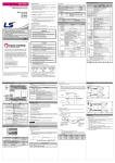
DATA SHEET
Safety Instructions
1. Introduction
►
To prevent injury and property damage, following these instructions.
►
Incorrect operation due to ignoring instructions will cause harm or damage, the seriousness
This data sheet provides brief information about characteristics, configuration, and usage of
of which is indicated by following symbols
the XGT Panel.
LS Programmable Logic Controller
Warning
LS Programmable Monitoring Unit
This symbol indicates the possibility of death or serious injury
2. General Specifications
Caution
XGT-Panel Series
This symbol indicates the possibility of injury or damage to
property
► The meaning of each symbol in this datasheet and on your equipment is as follows.
No
1
This is the safety alert symbol.
Read and follow instructions carefully to avoid dangerous situation.
This symbol alerts the user to the presence of “dangerous voltage” inside the
2
3
product that might cause harm or electric shock.
4
means paying attention because of danger of electrical shock.
Item
Specifications
Operating
temperature
Storage
temperature
Operating
Humidity
Storage
humidity
necessary. Always forward it to the end user.
Vibration
Warning
Do not contact the terminals while the power is applied.
►
Risk of electric shock and malfunction.
6
Shocks
Protect the product from being gone into by foreign metallic matter.
►
-10℃ ∼ +60℃ ( 14°F ∼ 140°F )
When using LSIS equipment, thoroughly read this datasheet
and associated manuals introduced in this datasheet. Also pay
careful attention to safety and handle the module properly.
- Store this datasheet in a safe place so that you can take it out
and read it whenever necessary.
►
Electrostatic
discharge
Radiated
electromagnetic
field
It can cause injury and fire by explosion and ignition.
7
Caution
Noise
immunity
Power supply connector
②
Mode switch
③
Variable resistor
④
RS-422/485 connector
RS-422/485 connector for communication channel 2
RS-232C connector
RS-232C connector for communication channel 1
2 pin connector for the external 24VDC input
DIP 1
DIP 2
RUN
RUN
Mode
Operating mode
O/S
O/S
O/S downloading mode
Variable resistor for adjusting contrast
4. Performance Specifications
Fast transient
/ Burst noise
► Be sure to check the rated voltage and terminal arrangement for the
Specifications
Item
5∼85%RH, non-condensing
Square wave
impulse noise
Do not charge, heat, short, solder and break up the battery.
①
⑤
Function
5∼85%RH, non-condensing
Risk of fire, electric shock and malfunction.
-
Name
0℃ ∼ +50℃ ( 32°F ∼ 122°F )
Occasional vibration
Sweep count
Frequency Acceleration Amplitude
10≤f< 57 ㎐
0.075mm
10 times
57≤f≤150 ㎐
9.8 ㎨
in each
direction
Continuous vibration
for
Frequency Acceleration Amplitude
X, Y, Z
10≤f< 57 ㎐
0.0375mm
57≤f≤150 ㎐
4.9 ㎨
* Maximum shock acceleration : 147 ㎨{15G}
* Duration time : 11 ㎳
* Pulse wave : half sine wave pulse
( 3 times in each of X, Y and Z directions )
► Store this datasheet in a safe place so that you can take it out and read it whenever
5
Standard
No
XP10BKA/DC
IEC61131-2
IEC61131-2
LSIS Internal
Standard
±500V
Voltage : 4 kV(contact discharge)
IEC61131-2,
IEC61000-4-2
27 ~ 500 MHz, 10 V/m
IEC61131-2,
IEC61000-4-3
Voltage
IEC61131-2,
IEC61000-4-4
1 kV
Remark
XP10BKB/DC
Input power
4.9 ~ 5.1VDC (RS-232C Connector),
21.6V ~ 26.4VDC (Power supply connector)
Display
LED Back-Light(192*64 Dot)
Communication
Interface
RS-232C, RS-422/485
Memory
256 Kbyte
Languages
English, Chinese, Korean
RTC
None
Speed : 115,200 bps
Each memory area can be up/downloaded in part
Keys
12 KEY (F1~F4,ESC,ALM,▲,▼,◀,▶,SET,ENT)
User area
System
flags
Standard Certification
Size (W x H x D)
Panel Cut (W x H)
Weight
Independent
2 channels
Supports
Up/Download spec.
System
memory
Refer to
User’s
Manual for
5VDC
M000 ~ M899 (900 Word)
Latch area is
supported, in
XP10BKB/D
C
M900 ~ M999 (100 Word)
-
UL/CE
150 x 93 x 35
141 x 87
0.4
(mm)
(mm)
(Kg)
module before wiring work.
8
Risk of electric shock, fire and malfunction.
► Tighten the screw of terminal block with the specified torque range.
10
If the terminal screw looses, it can cause fire and electric shock.
• HEAD OFFICE
LS tower, Hogye-dong, Dongan-gu, Anyang-si, Gyeonggi-do
1026-6, Korea http://eng.lsis.biz
Tel: 82-2-2034-4870
Fax: (82-2)2034-4648 e-mail: [email protected]
• LS Industrial Systems(ME) FZE _ Dubai, U.A.E.
Tel: 971-4-886-5360
Fax: 971-4-886-5361
e-mail: [email protected]
• LS Industrial Systems Tokyo Office _ Tokyo, Japan
Tel: 81-3-3582-9128
Fax: 81-3-3582-2667
e-mail: [email protected]
.
• LS Industrial Systems Shanghai Office _ Shanghai, China
Tel: 86-21-5237-9977(609) Fax: 89-21-5237-7189 e-mail: [email protected]
► Use the product in an environment that meets the general specifications
11
Atmosphere
Altitude for
use
Pollution
degree
Cooling
method
Free from corrosive gases and excessive dust
1) Up/Download interface
2 or lower
The PC and the XGT Panel should be connected by RS–232C
communication interface for up/downloading program data. Wiring is as
below.
Air-cooling
contained in this datasheet.
► Be sure that external load does not exceed the rating of output module.
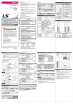
3. Names of Parts and Descriptions
Risk of fire and erroneous operation.
► Do not use the HMI in the environment of direct vibration.
Risk of electrical shock, fire and erroneous operation.
► Do not disassemble, repair or modify the HMI.
LS
Risk of electrical shock, fire and erroneous operation.
►
When disposing of HMI and battery, treat it as industrial waste.
Risk of poisonous pollution or explosion.
Download means that program data is transmitted from PC to the XGT
Panel, and upload is case to be opposed. Downloaded program data is
preserved permanently in state of being stored in flash memory even
though power is off.
To download program data to the XGT Panel, it must be powered with
DC 24V and connected to PC with up/download cable. Then use the
up/download menu of Panel Editor.
• LS Industrial Systems Chengdu Office _ Chengdu, China
Tel: 86-20-8328-6754
Fax: 86-20-8326-6287 e-mail: [email protected]
• LS Industrial Systems Qingdao Office _ Qingdao, China
Tel: 86-532-8501-6068 Fax: 86-532-8501-6057 e-mail: [email protected]
Precautions for use
► Do not detach PCB from the case of the product and do not modify the product.
► Cellular phone or walkie-talkie should be farther than 30cm from the product.
• LS Industrial Systems Europe B.V., Netherlands
Tel: +31 (0)20 654 1420 Fax: +31 (0)20 654 1429 e-mail: [email protected]
Input signal and communication line should be farther than minimum 100mm from a hightension line and a power line in order not to be affected by noise and magnetic field.
2010.10
⑤
10310000481(Ver.1.2)
Code
10310000482
④
Name
XGT Panel User’s Manual
③
carefully in order to use the product efficiently.
②
Before using the product, read the datasheet and the User’s manual through to the end
datasheet is subjected to change without notice.
2) RS–232C communication interface
①
Before handling the product
LS constantly endeavor to improve our products so that information in this
5. Communication Specifications
Up to 2,000m
Risk of electrical shock, fire, erroneous operation and deterioration of the HMI
• LS Industrial Systems Beijing Office _ Beijing, China
Tel: 86-10-5825-6027(666) Fax: 86-10-5825-6028 e-mail: [email protected]
• LS Industrial Systems Guangzhou Office _ Guangzhou, China
Tel: 86-20-8328-6754
Fax: 86-20-8326-6287 e-mail: [email protected]
9
With the RS-232C communication interface of the XGT Panel, data
communication with PLC, inverter and various kinds of control unit is
possible. In this case, communication cable must be connected properly.
Cable wiring for communication with LG PLC is as follow, and for more
details refer to the XGT Panel user’s manual.
* Continued from previous page.
키
Function description
- The function assigned to ◀ key is executed.
- If there is no defined function, go to the previous screen defined in the current
screen.
- When changing the value of the digit tag, move the current cursor position to
the left.
◀
7) Buzzer, backlight set
(1)
(2)
(3)
- The function assigned to ▶ key is executed.
- If there is no definition, go to the next screen defined in the current screen.
- When changing the value of the digit tag, move the current cursor position to
the right.
▶
SET
- Enter the value-changing mode.
ENT
- In value-changing mode, write the set value.
- Enter the setting menu.
- Execute the selected item in menu.
* G4M-CPUC in LS PLC does not support 5V supply.
3) RS–422/485 communication interface
With the RS-422/485 communication interface of the XGT Panel, data
communication like 1:1, 1:N multi-drop, N:M multi-master with PLC,
inverter and various kinds of control units is possible. In this case,
communication cable must be wired properly.
Cable wiring for communication with LS PLC is as follow, and for more
details, refer to the XGT Panel user’s manual.
(1)
3) N:M multi-master communication system configuration
The XGT Panel supports N:M multi-master and multi-slave communication. The XGT Panels which are set as a master communicate with slaves
in turn using the token. In this case, every XGT Panel set as a master
must have same communication setting data except HMI station number.
The total settable station number is 32.(station 0 – 31)
RS-422 communication wiring
If the key is valid the buzzer beeps 1 time, if not, 3 times.
If you select 5 of 6)-(1) menu, the volume level of the buzzer can be
adjusted.
If you select 6 of 6)-(1) menu, backlight can be ON/OFF.
In case that backlight option is selected, if no key is inputted during
setting time, backlight will be off automatically. In this case,
whichever key is pressed, the function assigned to the key is not
executed but backlight is just on.
8) Changing screen
(1)
(2)
(3)
(4)
When the power is supplied to a XGT Panel, the defined first screen
will be displayed. If it doesn’t exist, the first defined screen will be
displayed.
In monitor mode, the defined screen list will be displayed if ESC key
is pressed. Using ▲, ▼, ENT key, it is possible to change the screen.
In monitor mode, pressing ◀, ▶ key, the screen will move to the
defined previous, next screen for each. If the screen doesn’t exist, no
move will happen.
In case that screen saver option is set, if no key is inputted during
setting time, the screen will be move to the defined screen. At this
time, whatever key is inputted, the screen won’t move and the
function assigned to the key will be executed. If the screen doesn’t
exist, no move will happen.
3) Writing data
9) Continuous keystroke
(1)
The tags which are possible to write the data are digit tag and button
tag. But in case that password is set, password must be unlocked
before writing the data.
In monitor mode, pressing the SET key leads to value-changing
mode. If there’s no tag to be written to, it will be invalid.
The cursor will be located on the nearest tag to the left top of the
screen.
If the SET key is pressed again, the cursor moves to the next writing
enabled tag.
In case of digit tag, after changing the value of the tag with arrow
keys, execute writing the value with ENT key. In case of button tag,
when the cursor is located on the tag, execute the order defined on
the tag with ENT key.
(2)
(3)
(4)
(5)
When pressing a key, if the key is held down for more than 1 second, the
function assigned to the key will be executed repeatedly.
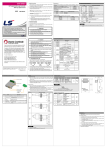
8. Dimension(mm)
1) External dimension
LS
4) Alarm
(2)
(1)
RS-485 communication wiring
(2)
In alarm state, the alarm message is displayed at the bottom of the
screen flickering. If the buzzer option is set, it will beep. At this time,
only ESC and ALM key are valid. In XP10BKB/DC type, two time
data will be saved. One data is the time when the alarm happened
and the other data is the time when it was cleared.
In monitor mode, the following messages will be displayed if ALM key
is pressed.
1. ALL ALARM LOG LIST
2. DEFINED ALARM LIST
120Ω, 1/2W Terminating Resistor is Recommended
If you select 1, the recent alarm messages will be displayed up to 100 items
in order
If you select 2, the recent Defined Alarm list will be displayed up to 10 items
in order.
7. Operation
1) Introduction
This chapter explains the operation of the XGT Panel. For more details
refer to the user’s manual.
This chapter describes information about the communication system configuration.
1) 1:1 communication system configuration
The XGT Panel has two independent channels which are RS-232C and
RS-422/485. It is possible to configure flexible 1:1 communication
system with them.
The following is an example configured with a XGT Panel, a PLC and an
inverter.
2) 1:N communication system configuration
This part explains 1:N multi-drop configuration with RS-422/485 channel
of the XGT Panel. In this case, the XGT Panel becomes a master and
other units become slaves.
The total settable station number is 32.(station 0 – 31)
5) Password
(1)
2) Key
Key
Function description
F1
- The function assigned to F1 key is executed.
- For details about the function, refer to the user’s manual
F2
- The function assigned to F2 key is executed.
F3
- The function assigned to F3 key is executed.
F4
- The function assigned to F4 key is executed.
ESC
- Display the names of screen defined.
- Cancel the change of the value, or go back in case of menu.
- In case of alarm, clear the alarm message displayed in the screen.
ALM
- Display alarm history.
▲
- The function assigned to ▲ key is executed.
- When changing the value of the digit tag, increase the number of the current
cursor position by 1.
- Move up the cursor in menu.
▼
- The function assigned to ▼ key is executed.
- When changing the value of the digit tag, decrease the number of the current
cursor position by 1.
- Move down the cursor in menu.
(2)
2) Cutting dimension
In case that password is set to the XGT Panel, it is impossible to
write data to the writing enabled tag and to execute the function key
set password at. In this case, it doesn’t operate normally until the
password is released.
In monitor mode, the following menu will be displayed if ENT key is
pressed.
87±0.5
6. Communication System Configuration
1. PASSWORD UNLOCK
2. PASSWORD LOCK
3. PASSWORD CHANGE
If you select 1, the password become unlocked if you input correct password.
If there is no password, the following message will be displayed.
141±0.5
PASSWORD NO EXIST!
In state that password is unlocked, the operations which is set password to is
executable.
This is valid until the password is locked.
If you select 2, the password is locked.
If you select 3, the password is able to be changed.
The password is less than 10 digits.
* If the password is set to 0, it is cleared.
Caution
►
Do not forget the password
If the password is forgotten, you may not be able to use the major functions
of the product.
9. Warranty
1. Warranty period
LSIS provides an 18-month-warranty from the date of the production.
2. Warranty conditions
For troubles within the warranty period, LSIS will replace the entire HMI or repair the
troubled parts free of charge except the following cases.
(1) The troubles caused by improper condition, environment or treatment except the
instructions of LSIS.
(2) The troubles caused by external devices.
(3) The troubles caused by remodeling or repairing based on the user’s own
6) Date / Time set(XP10BKB/DC type only)
* Continued on next page.
(1)
When the cursor is on 3 of 5)-(2) menu, pressing ▼ key leads to the
following menu.
4. DATE / TIME SET
5. BUZZER VOLUME SET
6. BACKLIGHT SET
If you select 4, current date and time will be displayed.
They can be changed with SET key.
The date and the day of the week must correspond.
discretion.
(4) The troubles caused by improper usage of the product.
(5) The troubles caused by the reason which exceeded the expectation
from science and technology level when LSIS manufactured the product.
(6) The troubles caused by natural disaster.
3. This warranty is limited to the HMI itself only. It is not valid for the whole system which the
HMI is attached to.


