1
JoysMaker User Manual
版本更新
时间
2013-01-15
主要内容
初始版本
3Djoy JoysMaker User Manual
1
2
3
4
5
6
7
1 Mechanics build guide ........................................................................................................ 4
1.0 What you'll need ....................................................................................................... 4
1.1Basic design concepts .............................................................................................. 4
Frame ....................................................................................................................................... 1
Frame assembled ........................................................................................................... 1
2.1
What you'll need........................................................................................................ 2
2.2
Step 1: Inserting the ball bearings ............................................................................. 3
2.3
Step 2: Limit switches ............................................................................................... 5
2.4
Step 3: Assembling the 'cube'-shaped frame ............................................................. 7
2.5
Step 4: Mounting various parts ............................................................................... 12
Motors .................................................................................................................................... 15
3.1
What you'll need...................................................................................................... 15
3.2
Step 1: The X and Y motors .................................................................................... 16
3.3
Step 2: The Z-motor ................................................................................................ 19
X-Y axes ................................................................................................................................ 21
4.1
What you'll need...................................................................................................... 21
4.2
Step 1: Assembling the X/Y slider blocks ............................................................... 22
4.3
Step 2: The claws .................................................................................................... 25
4.4
Step 3: Mounting the caps ....................................................................................... 27
4.5
Step 4: Mounting the axes ....................................................................................... 31
Extrusion head ...................................................................................................................... 37
5.1
Contents .................................................................................................................. 38
5.2
Step 4 - the EXTRUDER ........................................................................................ 38
5.3
What you'll need...................................................................................................... 38
5.4
Before you start, please read this carefully! ............................................................ 39
5.4.1
Lets start! ....................................................................................................... 41
5.5
Assembling the cooling fan ..................................................................................... 53
5.6
Mounting the housing to the XY-frame ................................................................... 56
5.7
What you'll need...................................................................................................... 56
5.8
Bowden cable / PFA tube ........................................................................................ 63
Z-stage ................................................................................................................................... 64
6.1
Requirements........................................................................................................... 64
6.2
Drive nut assembly .................................................................................................. 65
6.3
Left side arm ........................................................................................................... 66
6.4
Right side arm ......................................................................................................... 68
6.5
Putting it all together ............................................................................................... 69
6.6
Inserting the adjustable leveling screws .................................................................. 74
6.7
Preparing the bed for its first print .......................................................................... 76
6.8
Installing it in the machine ...................................................................................... 77
6.8.1
Grease it up ................................................................................................... 80
Material feed mechanism .................................................................................................... 81
2
3Djoy JoysMaker User Manual
7.1
Contents .................................................................................................................. 81
7.2
What you'll need...................................................................................................... 81
7.3
Step 1: Assembly of the main body of the drive mechanism .................................. 82
7.4
Step 2: Drive bolt assembly..................................................................................... 85
7.5
Step 3: Assembling the clamp ................................................................................. 89
7.6
What you'll need...................................................................................................... 89
7.7
Step 4: Mounting it to the machine ......................................................................... 96
7.8
Step 5: Filament holder ........................................................................................... 96
8 Mounting the electronics ..................................................................................................... 98
8.1
Step 1: What you'll need .......................................................................................... 98
8.2
Step 2: Installing the electronics ............................................................................. 99
8.3
Step 3: Preparing the electronics cooling system .................................................. 100
8.4
Step 4: Connecting the Heater ............................................................................... 104
8.5
Step 5: Connecting the printhead electronics ........................................................ 105
8.6
Step 6: Connecting the rest of the cables............................................................... 107
8.6.1
Tracing back cables limit switches ........................................................... 107
8.7
Step 7: Connecting the motor ................................................................................ 108
8.7.1
Tracking back cables motors .................................................................... 108
8.8
Step 8: Installing the electronics cooling system................................................... 109
8.9
Step 9: Strain relief ................................................................................................ 110
8.10
Step 10: Checking and aligning the Z-homing switch .......................................... 111
8.11
Troubleshooting the mechanics ............................................................................. 112
8.12
What's next? .......................................................................................................... 112
9 Software setup guide ......................................................................................................... 113
9.1
Setting up the JoysMaker 3D printing software .................................................... 113
9.2
Contents ................................................................................................................ 113
9.3
Download .............................................................................................................. 114
9.4
Documentation ...................................................................................................... 114
9.5
Using Cura ............................................................................................................ 114
9.6
Preparing a model file for printing ........................................................................ 114
9.7
Troubleshooting .................................................................................................... 115
9.8
Linux Dependencies .............................................................................................. 115
10
Troubleshooting .......................................................................................................... 116
10.1
Problems by observation ....................................................................................... 116
10.1.1 Printing in material A worked fine, now material B doesn't print well! . 116
10.1.2 Brown sludge forms on the extruder head .............................................. 116
10.1.3 Plastic comes out of extruder head in a flowing state ........................... 116
10.1.4 The extruder stops extruding .................................................................... 116
10.1.5 The first layer doesn't stick! ....................................................................... 117
10.1.6 My 3D prints do not look good! ................................................................. 118
10.2
Mechanical problems ............................................................................................ 119
10.2.1 X/Y axis ........................................................................................................ 119
10.2.2 Z-axis ............................................................................................................ 121
10.3
Electrical problems ................................................................................................ 122
1
3
3Djoy JoysMaker User Manual
1 Mechanics build guide
1.0 What you'll need
Time needed:
In total, for most people it takes between 6 and 20 hours to
complete the assembly of a machine.
Tools needed:
1. Hex keys (1,5 and 2.0mm)
2. Using the included 2.0mm hex-screwdriver saves
an awful lot of time compared to an L-shaped
hex-wrench!
3. Adjustable wrench or large size pliers
4. Consider also a cordless lithium-ion screwdriver
(e.g. Bosch IXO) with a 2.0mm hex bit.
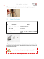
An 3Djoy kit comes with many packs. See the page for your batch to check its contents.
There should be more nuts and bolts in the packs than you will need, so don't worry if you
have a few left!
1.1Basic design concepts
Metric
The design is almost completely metric (using millimeter and meters). Another system for
physical dimensions is imperial (inches and feet). The nuts and bolts used are mostly M3 they have a 3 millimeter diameter thread.
T-Slots and tabs:
4
3Djoy JoysMaker User Manual
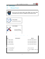
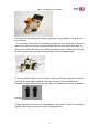
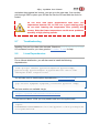
T-Slots and tabs
T-slots are used throughout the design to connect flat-pack parts at a 90 degree angle.
Note: Some pictures may show square nuts in places other than T-Slots; just
use hex nuts instead on your build.
5
3Djoy JoysMaker User Manual
2
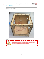
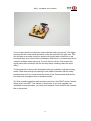
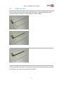
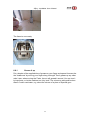
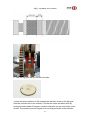
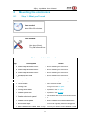
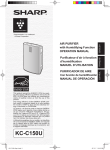
Frame
Frame assembled
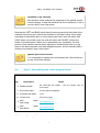
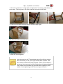
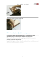
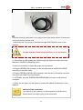
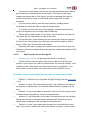
Note:
Check the laser cut parts. If needed, gently treat them with a
small piece of sandpaper to prevent splinters.
1
3Djoy JoysMaker User Manual
2.1
What you'll need
Time needed:
About 50 to 90 minutes.
Tools needed:
Hex keys (2mm)
5.5 mm socket wrench or pliers, for M3 Nylock nuts
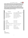
Parts needed in this section
Qty.
Description
Notes
6 Laser cut panels (Wood)
Marked LEFT, RIGHT, TOP, BOTTOM, (FRONT) and
BACK.
8 Ball bearings 8mm
Used for in the frame.
6 Limit switches
Wired.
4 Cable ducts
Black cable ducts made of kite fabric.
41 Hexagonal M3 nuts
Used anywhere else.
45
Socket
16mm
cap
M3
bolts
10
Socket
10mm
cap
M3
bolts
Used in the T-slots.
Used in X and Y switches, and lower Z switch.
2 M3 washers
Used for the (top) Z limit switch
1 Blue Scotch tape
The roll inside the Mega pack.
1 Laser cut part 11A
Reel holder retention plate.
2 Laser cut part 3A
Cover for 12mm diameter holes.
2 M3 Nylock nuts
4 Velcro
Used for reel holder retention plate, with blue plastic
inside.
Used to hold the wires together.
2
3Djoy JoysMaker User Manual
The complete frame is built with M3 hex-bolts, with lengths of 10, 16, 20 and
30mm.
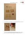
All panels are marked with the side they belong to.
For all the panels except the front panel, the engravings face
towards the inside of the machine. The front panel has the
"JoysMakers" engraving on the outside.
The bottom panel has the engraving faced downward.
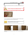
Sanding.
Before starting the assembly, you may want to slightly sand the
panels to remove any burn marks / blemishes from the laser cutting
process. You can also paint or stain your JoysMaker. Be aware
though that paint will not take very well on the brown cutting edges.
If you have received a painted JoysMaker, wipe the smoke marks off
with a green scouring pad and soapy water
Check the Z-Axis holes.
Check if the Z-Axis rods (the really thick ones) fit the 2 holes of the
Top and Bottom panel. You will later push both rods through the Top
panel all the way down into the bottom. If this seems impossible, turn
some sandpaper in the holes. Don't sand too much! The rods should
be held firmly in place by the wood. They should not turn easily.
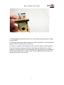
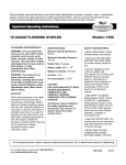
2.2
Step 1: Inserting the ball bearings
Needed in this step
Qty.
Description
Notes
1 Front panel
Wooden panel with the JoysMaker logo.
1 Back panel
Wooden panel marked BACK.
1 Left panel
Wooden panel marked LEFT
1 Right panel
Wooden panel marked Right
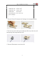
8 Ball bearings 8mm Used for in the frame.
3
3Djoy JoysMaker User Manual
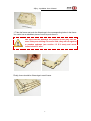
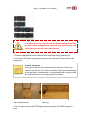
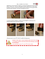
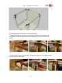
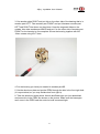
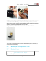
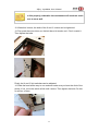
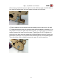
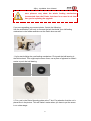
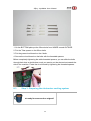
1. Take the frame and push the 8 bearings in the corresponding holes in the frame.
You could use a redundant piece of wood to push them in.
Make sure that the bearings are pushed all the way into the
frame. If they are sticking out even a little, they will rub against
the wooden endcaps (see section 1.3 X-Y axes) and cause
friction in the X/Y axes.
Finally, there should be 2 bearings in each frame.
4
3Djoy JoysMaker User Manual
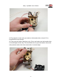
2.3
Step 2: Limit switches
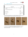
Needed in this step
Qty.
Description
Notes
1 Front panel
Wooden panel with the JoysMaker logo.
1 Back panel
Wooden panel marked BACK.
1 Left panel
Wooden panel marked LEFT
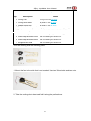
5 Long Limit switches
Small black box with long twisted wires.
1 Short Limit switches
Small black box with short twisted wires.
10 M3 socket cap bolts 10 mm 10 mm long
2 M3 socket cap bolts 16 mm Used in Limit switches, top backside.
2 Washers
Small flat metal rings
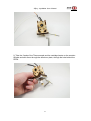
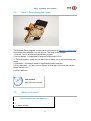
Limit switches (or 'end stops') make sure the machine stops movement of the
carriage when it is at the edge of printing volume.
Don't strain the tapped thread on the inside of the switch
housing by putting a lot of force on the bolts. All limit switches
are pre-tapped, you can fasten them directly with M3 bolts, no
nuts required here!
5
3Djoy JoysMaker User Manual
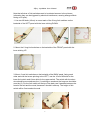
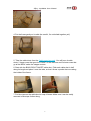
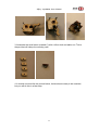
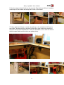
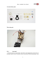
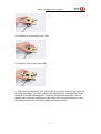
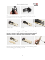
Note that all wires of limit switches need to be twisted as seen in the pictures
(otherwise they can be triggered by electrical interference, causing strange effects
during a 3D print).
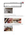
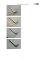
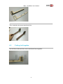
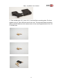
1. Use two M3 bolts (10mm) to mount each of the 2 long limit switches on the
backside of the LEFT panel with the lever sticking DOWN.
2. Mount the 2 long limit switches on the backside of the FRONT panel with the
lever sticking UP.
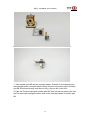
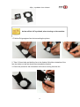
3. Mount 2 rest limit switches on the backside of the BACK panel, facing each
other and with the levers pointing to the LEFT, use the 10 mm M3 bolts for the
lower limit switch and 16mm bolts for the upper switch. The switch with the short
wire should be mounted near the (1) marking on wood and the long one should be
near the (2). For the limit switch on the top of the back use 2 washers between the
head of the bolt and the wood, because it shouldn't slide up. The height of this
switch will be fine-tuned at the end.
6
3Djoy JoysMaker User Manual
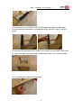
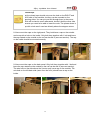
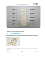
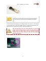
Orientation of the switches
The orientation of the switches are engraved on the panels, except
for the frontpanel. In total the machine has 6 limit switches: (1 has a
short wire and 5 have long wires).
Note that the LEFT and BACK panel have the text engraved on the inside of the
machine (now facing you). Mount the switches to the panels using 10mm bolts,
according to the pictures above. On the back panel make sure the switch with
LONG wires is mounted on the top, and the switch with SHORT wires at the
bottom of the back panel. When you've assembled your JoysMaker, the final
position of the switches can be easily adjusted by loosening the bolts, moving
them to the desired position and then retightening them. An axis should make a
clicking sound when it trips a limit switch.
Tightening the limit switches
If it is not possible to tighten the limit switches with 10mm bolts you
can use 12mm bolts instead.
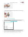
2.4
Step 3: Assembling the 'cube'-shaped frame
Needed in this step
Qty.
Description
Notes
TOP, BOTTOM and RIGHT , plus the panels from the
6 Wooden panels
previous step.
1 Blue Scotch tape
The roll inside the Megapack.
37 M3 socket cap bolts
16 mm.
37 M3 Hex nuts
Used for the frame.
2
Black
ducts-Long
cable
2
Black
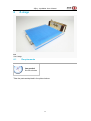
ducts-Short
cable
cable organizer pack
cable organizer pack
Cable ducts(For JoysMaker lasted version, we don’t provide this, but
7
3Djoy JoysMaker User Manual
replaced by Magic belt)
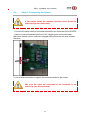
Be careful not to put any force on the panels because the they
are weak in this configuration; however they will become very
sturdy once you mount a few more panels.
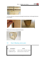
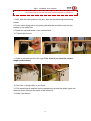
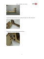
1. Place the back panel on the table with the markings facing towards you.
2. Insert the TOP panel by placing the tabs of the top panel into the slots of the
back panel.
Tip when mounting
The top panel should fit into the back such that four T slots (not
three) line up with the four holes in the back. Also, don't accidentally
put the top plate in upside-down. It is symmetrical left to right and will
work upside-down, but the engraving will be visible.
Top and back panel
(close up)
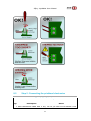
3. Do the same with the BOTTOM panel and then place the FRONT panel on
both:
8
3Djoy JoysMaker User Manual
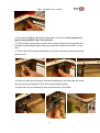
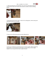
4. Put the frame gently on its side (be careful, it's not bolted together yet!)
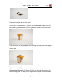
5. Take the cable ducts from the Cable organizer pack. You will have 4 cable
ducts, 2 longer ones that go at the FRONT of the machine and 2 shorter ones that
go at the BACK under the stepper motors.
6. Start with the BACK-RIGHT SHORT cable duct. Fold each cable duct in half
along its length and place it over the tabs, so that it forms a pocket that runs along
the inside of the frame.
7. Put blue tape on the cable duct to keep it folded. Make sure it can be easily
removed a few steps further along.
9
3Djoy JoysMaker User Manual
8. Do the same for the FRONT-RIGHT LONG cable duct (also use blue tape).
Ensure the small round holes in the cable duct align with the T slots in the front
panel.
9. Now that both cable ducts are in place, you're ready to fit the RIGHT side panel.
Fix with a few bolts, you might need to disassemble later if you made a mistake.
10. If everything fits, remove the blue tape.
10
3Djoy JoysMaker User Manual
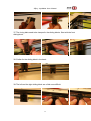
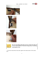
11. Turn the machine on its right side and place the 2 remaining cable ducts in a
similar way. The long one on the front, and the short one on the back.
12. Place the left side panel and remove the blue tape again.
The frame should now look like this:
13. Bolt the frame together.
Inserting nuts
Insert the nuts into the T-slots where they will not fall out (where
panel is vertical), or use your finger to keep them in place. Use
16mm bolts to fasten the panels together. Add a nut and fasten it,
then go on to the next one, until the whole frame is fastened together
nicely. Make sure no cables get jammed before tightening. Also,
beware of overtightening, since the wood gives in easily.
11
3Djoy JoysMaker User Manual
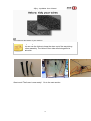
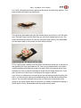
14. Then guide the end stop wires through the cable ducts and through the holes
in the corners.
When done, the frame should look like this:
2.5
Step 4: Mounting various parts
Needed in this step
Qty.
Description
Notes
4 Pieces of Velcro
To hold the wires on the bottom together.
1 Wooden part 11A
A square block with 4 square holes.
2 Wooden part 3A
To cover the holes at the bottom panel
6 M3 socket cap bolts 16 mm.
12
3Djoy JoysMaker User Manual
4 M3 Hex nuts
not the square ones.
2 M3 Nylock nuts
with blue plastic inside.
1. Mount the reel holder retention plate (11A) with Nylock nuts (blue plastic on the
inside).
This panel is mounted on the outside of the machine and two
16mm bolts are inserted from the INSIDE of the frame.
2. Mount 2 parts labeled 3A on the underside of the machine (at the back) using 2
16mm bolts and let them cover the 12mm diameter holes.
These parts should be 6mm thick. The 4mm thick ones are used
at the top after the 12mm rods are inserted.
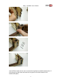
3. Slide the 4 pieces of black Velcro through the 4 holes on the BOTTOM panel of
the machine.
13
3Djoy JoysMaker User Manual
mount these at the bottom of your machine.
Organizing cables
You can use the Velcro to keep the wires out of the way during
further assembly. The Velcro's front side will stick against its
back-side.
Great work! The frame is now ready!
On to the next section.
14
3Djoy JoysMaker User Manual
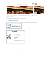
3
Motors
3.1
What you'll need
Time needed:
About 20 to 40 minutes.
Tools needed:
Hex key (2mm)
Hex key (1.5 mm)
Parts needed in this section
Qty.
3
Description
Motors with
round axles
Notes
simple the one with the short wire is for the Z-axis, the 2 other for X
and Y. The fourth one is for the extruder later.
1 spacer pack
For the X-Y-motor.
8 Bolts 20 MM
For the X & Y motors.
4 Bolts 10 MM
For the Z-motor.
2 Short timing belts
For the X & Y motors.
8 Washers
Should fit on the bolts
2 Pulleys
For the X & Y motors.
1 Resiliert coupling
For the Z-motor.
15
3Djoy JoysMaker User Manual
3.2
Step 1: The X and Y motors
Parts needed in this section
Qty.
2
Description
Notes
Motors with simple round The one with the short wire is for the Z-axis, the 2 other
axles
for X and Y.
2 Pulleys
For the X & Y motors.
2 Short timing belts
For the X & Y motors.
8 Bolts 20 mm
For the X & Y motors.
8 Washers
Should fit on the bolts.
8 White spacers
For the X and Y motors.
For this step you have to take 2 motors with long wires.
16
3Djoy JoysMaker User Manual
1. Prepare the two motors by placing the 5mm internal diameter pulleys on the two
motors. Keep a tiny gap in between the motor and pulley and fasten it very tightly.
Because of the tiny gap, the pulley should rotate freely.
2. Put 4 bolts (20mm) with washers through the holes on the outside (not
engraved) of the BACK panel on the place where the motor needs to be mounted.
Next, take 4 white spacers and place each one around one of the bolts (on the
engraved side of the frame).
3. Take one of the motors and lay the timing belt around the pulley.
17
3Djoy JoysMaker User Manual
4. Put the motor in place. Make sure the wires of the motor, the wires of the limit
switches and the timing belt don't get stuck!
5. Hold the motor with the timing belt and tighten it just a little bit with the 4 bolts,
so it can slide up and down a little. These bolts will be tightened later when all
axes are in place.
Mounting the washers
You should use 4 washers on the bolts in the X and Y motors to
ensure that the motors will not slide upward. This helps maintain belt
tension for the short belts. If you somehow do not have 3mm
washers in the nuts and bolts pack, you can use any 3mm (or 1/8
inch) washer from the hardware store.
6. Do the same for the Y motor and mount this one to the LEFT panel. Make sure
you push the cables into the corner before mounting the Y motor.
18
3Djoy JoysMaker User Manual
7. Push the wires through the cable ducts and out through the bottom panel.
3.3
Step 2: The Z-motor
Parts needed in this section
Qty.
1
Description
Notes
Motors with simple round
the one with the short wire.
axles
4 Bolts 10 MM
For the Z-motor.
1 Resiliert coupling
For the Z-motor.
1 Hex key
The small one, used for tightening the Resiliert
coupling.
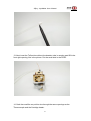
1.Take the third motor (with the shortest wires) and mount on the underside of the
bottom panel. Use 4 bolts of 10mm. Make sure that the wires stick out towards the
center of the bottom panel.
Because there is no clearance between the motor and the back,
be sure to force the motor face to seat flat on the bottom.
19
3Djoy JoysMaker User Manual
2. Take the Resiliert coupling (you can find it within the little white package in the
Pulley Pack) and place it on top of the motor. The Resiliert coupling has two
different sides, a 5mm and an 8mm - you need to put the 5mm side on top of the
motor.
3. Use a screw driver to set the Resiliert coupling at the right height and tighten the
small screws at the bottom of the Resiliert coupling with the hex key.
20
3Djoy JoysMaker User Manual
4
X-Y axes
4.1
What you'll need
This is one of the more tricky steps. Make sure you're fully
caffeinated and/or relaxed, or whatever works best for you!
Time needed:
About 60 to 90 minutes.
Tools needed:
Hex keys (2mm)
Hex key (1.5 mm)
Parts needed in this section
Qty.
Description
Notes
16 Bolts 16mm
Used for the bushing blocks.
16 Bolts 30mm
Used for the bushing blocks.
16 Bolts 10mm
Used for the bushing blocks.
56 M3 Hex Nuts
Used for the bushing blocks.
2 8 mm Axes short
Works as a slider for the belt.
2 8 mm Axes long
Works as a slider for the belt.
10 Timing pulleys
Used for on the axis.
Will work together with the
4 Timing belts
pulleys.
24 Wooden parts
See picture in step 2
21
3Djoy JoysMaker User Manual
8
Linear bronze bushings 8 mm x 11mm x 15mm
Needed in step 2
long
4 wooden part insert marked C
Needed in step 3
8 wooden caps without hole
See picture in step 4
6 wooden caps with hole
See picture in step 4
4.2
Step 1: Assembling the X/Y slider blocks
Parts needed in this step
Qty.
Description
Notes
16 Bolts 30 mm
See picture below
8 Bolts 10 mm
See picture below
28 M3 Nuts
See picture below
24 wooden parts
See picture below
4 linear bearings 8 mm x 11mm x 30mm long
22
Found in axes pack, See picture
below
3Djoy JoysMaker User Manual
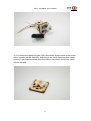
1. Push the bearing in part FRONT A. Use a redundant piece of wood to push it in.
2. Put it on top of part FRONT B and push 2 bushing further in.(note, in bellow
picture it showed as 1 30mm long bushing, but for JoysMaker version, it is
23
3Djoy JoysMaker User Manual
replaced by 2 15mm bushing. Problem for it will be the alignment for two bushings.
Here is a way to do it: after you assemble the slider and push the 2 15mm long
bushings in, you can mount it into the 8mm axes, and knock it to the ground with
the plane side downward, it will solve the alignment issue.)
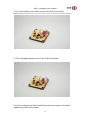
3. Continue with part FRONT C, FRONT D and FRONT E, until all parts are
stacked together and the bushing is inside.
4.Do the same for the LEFT, RIGHT and BACK sliding block.
Assemble each block in the following order A-B-C-D-E (from
top to bottom) with the text facing the same direction on each
part of the block.
Once assembled only the "A" on the TOP will be visible.
24
3Djoy JoysMaker User Manual
4.3
Step 2: The claws
Parts needed in this step
Qty.
4
Description
Notes
wooden parts marked FRONT C, RIGHT C, LEFT C and needed
BACK C
claws
for
the
needed
for
the
for
the
4 wooden parts insert marked C
claws
needed
8 Bolts 10mm
claws
16 Bolts 30 mm
See picture below
needed
12 M3 Nuts
for
the
claws
1. Use a 10mm bolt and two hex nuts in order to assemble the 'claw' part that will
grab onto the timing belt. The hex nut will just barely fit, this is normal.
2. Now place 3 of the 30mm bolts on the side with the text markings, and add the
nuts on the other side.DON'T TIGHTEN THEM TOO MUCH YET, the clamp
should be able to rotate!
25
3Djoy JoysMaker User Manual
3. Assemble the small insert (marked C) with a 10mm bolt and add a nut. This is
the part that will clamp the crossing rods.
4. It should now look like the picture below, the blocks are ready to be mounted,
but you will do this in a later step.
26
3Djoy JoysMaker User Manual
4.4
Step 3: Mounting the caps
Parts needed in this step
Qty.
Description
Notes
8 wooden caps without hole See picture below
6 wooden caps with hole
See picture below
16 M3 Nuts
See picture below
16 16 mm Bolts
See picture below
1. Now the caps can be mounted so the axes will stay in place and won't slide out
during operation. The order in which the caps should be mounted is quite
important. In the picture below, you'll see how the axes can be slid in from the right
and back side, so the caps on those sides should only be partly mounted.
27
3Djoy JoysMaker User Manual
2. Follow the order of the caps in the pictures below!!
3. Start with the cap on the front of the machine. Start with the left cap on the
frontpanel. It needs a closed cap on the outside and a cap with a hole on the
inside.
4. Follow with the cap on the front right. It needs a closed cap on the outside and a
cap with a hole on the inside.
28
3Djoy JoysMaker User Manual
5. Now the caps on the left side can be mounted. Start with the left front. It needs a
closed cap on the outside and a cap with a hole on the inside.
7. Follow with the left back. It needs a closed cap on the outside, but NO cap on
the inside. The bearing will be secured in place by a gear inside the machine on
the axes which will be installed later. Check the illustration, above with the red and
the blue caps. Make sure the wires are guided nicely.
29
3Djoy JoysMaker User Manual
Closed caps
that the closed caps should not cover the hole on the RIGHT and
BACK side of the machine, but they can be mounted on the
opposing sides. You can put one bolt through them in the corner
which will be hard to reach afterwards, but don't bolt the other side,
because you need to be able to insert the rods. The places where a
cap with a hole aren't used are directly above the stepper motors.
8. Now mount the caps on the right panel. They both have a cap on the outside
and a cap with a hole on the inside. Only bolt them together with 1 bolt and leave
the cap rotated on the outside so the rod can be slid in (see next section). The cap
on the inside should be mounted correctly.
9. Now mount the caps on the back panel. Only bolt them together with 1 bolt and
leave the cap rotated on the outside so the rod can be slid in (see next section).
The axis hole on the side above the X-motor only has a cap on the outside. The
axis hole on the left-back side (seen from the front) should have a cap on the
inside.
30
3Djoy JoysMaker User Manual
4.5
Step 4: Mounting the axes
Parts needed in this step
Qty.
Description
Notes
2 8 mm Axes short Works as a slider for the belt.
2 8 mm Axes long Works as a slider for the belt.
8 Timing pulleys
Used for on the axis.
4 Timing belts
Will work together with the pulleys.
1. Start with the front axes.
2. Check if you have the correct length of axis. There are 4 axes with a diameter of
8mm--2 are short and fit left side to right side, and 2 are a little longer and fit front
to back. For the first axis, pick one of the shorter ones.
3. Slide the axis in the front of the machine.
4. Then put 1 timing pulley on the axis with the fastening screw of the pulley like in
the picture.
5. Take 1 timing belt and place it around the pulley.
6. Then slide the FRONT sliding block on the axis, text readable and the text
facing LEFT side of the machine.
VERY IMPORTANT: Orientation of the Axes
Mind the orientation! The hinge mechanism of the sliding blocks
should be facing DOWN for the FRONT and BACK Axis and they
should face UP for the LEFT and RIGHT axis. The part C of the
sliding blocks should always be facing inwards the machine. See the
picture below for correct placement of the timing pulleys and sliding
block. In general each of the blocks will be clamping onto a belt
attached to a pulley on a rod going in the other direction, the hinge
31
3Djoy JoysMaker User Manual
on the block will be on the side that the belt passes by the block.
7. Next, slide the other pulley on the axis, also with the fastening screw facing
inward.
8. Do the other timing belt on the pulley and slide the axis all the way into the
bearing on the other side.
9. Rotate the cap and fasten it with a second bolt.
10. Tighten with the nut.
11. Slide in the back axis from the right. First check if you have the correct
length (a short axes).
12. First take 1 timing pulley in your hand,
13. Put the belt that is attached on the opposite axis around the pulley (again the
fastening screw facing to the inside of the machine).
14. Slide it on the axis.
32
3Djoy JoysMaker User Manual
15. Now take the BACK sliding block and slide it on the axis, text readable and
the text facing RIGHT side of the machine.
16. Take another timing pulley and put the second timing belt of the opposite axis
around the pulley (fastening screw facing inward the machine) and slide it on the
axis.
17. Take a third timing pulley and slide it on the axis in the same orientation as the
previous one.
18. Move the axis with the pulleys towards the bearing on the other side, but make
sure you put the timing belt of the motor around the third pulley.
19. Slide the axis into the bearing and mount the cap on the frame.
33
3Djoy JoysMaker User Manual
20. Slide in the left axis [a longer one] from the back of the machine (i.e. the top
left corner when the machine is face down).
21. Put 1 timing pulley on the axis with the fastening screw facing inward the
machine.
22. Take 1 timing belt and place it around the pulley.
23. Slide in the LEFT sliding block, text readable and the text facing FRONT
side of the machine.
24. Slide the second timing pulley on the axis, with the fastening screw facing
inward the machine.
25. Take another timing belt and place it around the second timing pulley.
26. Slide the axis all the way into the bearing and fasten the cap.
Do yourself a favour and put the timing belt already in the
clamp mechanism. It will save you some fiddling later on.
27. Finally the right axes can be put in place.
28. Slide in the right axis [a longer one] from the back of the machine (i.e. the top
right corner when the machine is face down).
34
3Djoy JoysMaker User Manual
29. Put 1 timing pulley on the axis with the fastening screw facing inward the
machine.
30. Take the long timing belt from the front of the machine and place it around the
pulley.
31. Slide in the RIGHT sliding block, text readable and the text facing BACK
side of the machine.
32. Slide the second timing pulley on the axis, with the fastening screw facing
inward the machine.
33. Take the long timing belt from the back of the machine and place it around the
second timing pulley.
34. Slide the third timing pulley on the axis, with the fastening screw facing inward
the machine.
35. Take the timing belt from the X-motor and put it on the pulley.
36. Slide the axis all the way into the bearing and fasten the cap.
When you bolt the motor, make sure you push it downward so
that the small timing belt is completely tight, otherwise this will
cause backlash. When the motors get hot and cool down a few
cycles, this may allow the bolts to sink into the wood a little,
causing the X and Y stepper motor to start sliding upward
again. You can prevent this by tightening it more in advance, or
by re-tightening it when it has heated up and cooled a few
times.
Again do yourself a favour: put the timing belt already in the
clamp mechanism to avoid some fiddling.
35
3Djoy JoysMaker User Manual
37. The timing belts need to be clamped in the sliding blocks. Start with the front
sliding block.
38. Similar for the sliding block in the back:
39. The left and the right sliding block are a little more difficult.
36
3Djoy JoysMaker User Manual
40. You should now have four C parts left for the sliding blocks, you will use them
in the next chapter.
41. Take a sip of you coffee and relax for a moment.
5
Extrusion head
Time needed:
About 60 to 90 minutes.
Tools needed:
Hex keys (2mm)
Hex key (1.5 mm)
Tweezers
Pliers
Small screwdriver (1.5 mm)
37
3Djoy JoysMaker User Manual
5.1
Contents
[hide]
1 Step 4 - the EXTRUDER
2 What you'll need
o
2.1 Parts needed in this section
3 Before you start, please read this carefully!
o
3.1 Parts needed in this section
o
3.2 Lets start!
4 Assembling the cooling fan
o
4.1 Parts needed in this section
5 Mounting the housing to the XY-frame
6 What you'll need
o
6.1 Parts needed in this section
7 Bowden cable / PFA tube
8 Questions or comments regarding this page? Let us and others
know!
5.2
Step 4 - the EXTRUDER
5.3
What you'll need
Parts needed in this section
Qty.
Description
6 m3 nuts
5 m3 bolts 10 mm
2 m3 bolts 30 mm
4
Notes
2 used to mount for thermocouple, 4 used in the
extrusion frame.
1 for the heating part, 4 used in the extrusion
frame.
Used to mount the thermocouple.
wooden parts named FRONT,
Named with 8A which means that they fit in 8A.
BACK, RIGHT, LEFT
1 wooden part named 8B
1 wooden part named 8B
This one can be found in the extrusion pack, and
is milled on one side in two holes.
this one is from the laserpack, NOT MILLED and
NOT NEEDED.
38
3Djoy JoysMaker User Manual
1 wooden part named 8A
looks like 8B but this one is NOT milled.
2 linear bearings
Metal tubes.
1 push in fitting
Tiny small plastic tube.
1 PFA tube
Transparent tube, one side taped blue.
1 horse shoe
iny blue U-shaped plastic that will stick later on
the fitting.
1 m6 brass pipe*
*these pieces might be screwed together.
1 nozzle bolt*
*these pieces might be screwed together.
1 aluminium heater block*
*these pieces might be screwed together.
1 aluminium plate
with 4 holes.
1 peek insulator
with m6 screw-thread inside.
1 tiny piece of plumbing tape
needs to be used in between the peek and brass
pipe.
1 heater
solid metal pipe with wires.
1 thermocouple
smaller solid metal pipe with wires.
1 thermocouple board
Tiny green board with electronics.
1 comb-shaped strain relief
tiny black plastic.
2 White plastic nuts
will fit the 2 30mm bolts.
1 tiny transparant acrylic
should be mounted underneath the thermocouple
board.
4 m3 studding
long bolts, +-95 mm with a black top part.
1 cooling fan
Used the assemble the cooling fan.
1 black polypropylene fan duct
Used the assemble the cooling fan.
2 m3 bolts 16 mm
Used the assemble the cooling fan.
4 m3 hex nuts
Used the assemble the cooling fan.
4 wooden parts named C
used for the tensioning of the belts.
2 6mm axis
sliders for the extrusion head.
4 30mm m3 bolts
used for mounting the housing of the XY frame.
4 m3 nuts
used for mounting the housing of the XY frame.
5.4
Before you start, please read this carefully!
39
3Djoy JoysMaker User Manual
If you are updating from Hot end V1, you have to disassemble your extruder
head first. Unscrew the small C parts in the sliding blocks that keep your
axis in its place. Take out the X and Y axis. Remove them from the housing
and strip it from its parts gently. You have to re-use some parts. In the
picture below you can see what parts you need to upgrade to Hot End
V2. Note: The acrylic mounting plate and comb-shaped strain relief have a
slightly new design, please use the upgraded version. If this is the first time
you are building your extruder head, ignore these instructions and continue
reading the assembly guide below. Thank you.
Parts needed in this section
Qty.
1
Description
wood
FRONT/BACK/LEFT/RIGHT
Notes
These 4 wooden parts will create the center
piece, the housing of the extruder head.
1 Wooden part 8A
The top of the extruder head.
1 Wooden part 8B
The bottom of the extruder head.
1 Acrylic mounting plate
Goes under the amplifier circuit board
2 threaded spacers
Will hold your strain relief up.
1 PEEK
Part of the hot end
1 Aluminum heater block
Part of the hot end
1 Brass pipe
Part of the hot end
1 0.4 Nozzle
Part of the hot end
1 Strain relief
Protect your wires
1 Teflon insulator
Part of the hot end
1
Bowden tube clamp, colours may
Will hold the bowden tube at its place
vary
1 Horseshoe, colours may vary
Keeps the tightner under tension
2 Lineair bearing
For the axes
1 Cartridge heater
Will heat your hot end
1 Thermocouple
Will read the temperature
1 Aluminum plate
For under the extruder head
1 Amplifier circuit board
Goes on top of the extruder head
Tools
1 HEX-screwdriver
1 Small flat screwdriver
40
3Djoy JoysMaker User Manual
You need these parts
This is the goal:
5.4.1
Lets start!
1. Grab the aluminum heater block, and hold it so the biggest hole at the side is at
the right- bottom corner. Screw the nozzle in the bottom, and the brass pipe on top
41
3Djoy JoysMaker User Manual
like show on the picture. Pay attention that the brass pipe isn't showing a thread
on the part that sticks in the aluminum heater block.
2. Now get the 4 wooden sides from the housing marked with FRONT, BACK,
LEFT and RIGHT. Put these in front of you with the markings facing up. Take 1
lineair bearing and stick it in the back of wooden plate FRONT, without letting it
stick out from the front. Repeat this with the other bearing and wooden plate
LEFT.
42
3Djoy JoysMaker User Manual
3. Get wooden plate RIGHT and put this on the other side of the bearing that is in
wooden part LEFT. Take wooden part FRONT and put it between wooden part
LEFT and RIGHT like shown on the picture. Keep the engraved sides on the
outside. Now take wooden part BACK and put it on the other side of wooden part
FRONT so the housing is now complete. Screw the housing together with M3
10mm screws using the T-slots.
4. Put the housing you have just created in wooden part 8B.
5. Get the aluminum plate and put the PEEK through the hole in the front right hole.
(it is symmetrical, so you may decide what front right is).
6. Take the aluminum heater block, Nozzle and Brass pipe you just assembled
and screw this in the PEEK like shown on the picture. Make sure the brass pipe
can't move in the PEEK and the entire hot end is screwed tight.
43
3Djoy JoysMaker User Manual
7. Take wooden part 8B and the cartridge heater. Grab the 2 wires belonging to
the cartridge heater, and stick these through the hole in the back right of wooden
part 8B. Stick them through until there is only a few cm left in the front.
8. Take the Thermocouple and wooden part 8B. Stick the red and yellow wire from
the Thermocouple through the same hole as the cartridge heater in wooden part
8B.
44
3Djoy JoysMaker User Manual
9. Take the 2 ends of the Thermocouple and the cartridge heater on the wooden
8B side and stick them through the aluminum plate, through the hole behind the
PEEK.
45
3Djoy JoysMaker User Manual
10. Now put the Thermocouple and the Cartridge heater in the Aluminum heater
block in the designated opening. Make sure they are all the way in the Aluminum
heater block and do not touch each other like in the picture. The cartridge heater
should be stick out a little bit on the other side.
CAUTION
You should put the thermocouple and cartridge heater in the
back of the heater block. Up until this point you can rotate the
hot end freely so rotate like shown on the picture. The picture is
showing the back of the hot end v2.
11. Now make sure the Cartridge heater and Thermocouple are stuck by screwing
in an M3 10MM screw like on the picture.
12. Put this on the side, and grab the teflon tube and the side of the bowden tube
WITHOUT the blue tape. Stick this end in the teflon tube and mark your bowden
tube so you will know how far it can go in.
46
3Djoy JoysMaker User Manual
13. Next insert the Teflon tube without the bowden tube in wooden part 8B in the
front right opening, like in the picture. Put the small side in the PEEK.
14. Grab the small fan en put this wire through the same openings as the
Thermocouple and the Cartridge heater.
47
3Djoy JoysMaker User Manual
15. Put the housing aside and take 2 M3 16mm Bolts and put these in the bottom
side of wooden part 8A (MILLED), and through the acrylic mounting plate. Make
sure the 3 openings are aimed at the front like on the picture, and put the milled
side on the table.
48
3Djoy JoysMaker User Manual
16. Put the Amplifier Circuit board on top of the 2 M3 16mm bolts.
17. Put 2 threaded spacers on top of the 2 M3 16mm Bolts.
18. On top of this put the Strain relief like shown on the picture. Screw this
together with 2 M3 10mm screws.
49
3Djoy JoysMaker User Manual
(You can also decide to install your strain relief the other way around. The bigger
opening with the screw inside should be on the left instead of the right side. This
can be done as an extra security to prevent the signal cable connection to get
loose and keep your hot end from overheating. Note that it is not necessary due to
a build-in software safety measure. If you do want to do this, first connect the
signal cable (the connection with the red dot) before screwing down the strain
relief.)
19. Now grab the 2 wires of the Cartridge heater you pulled through the housing
earlier. Stick them through the opening in the middle of wooden part 8A. Keep
inserting them until you come across the wires of the Thermocouple and the fan.
Put these also through the hole in wooden part 8A.
20. Grab a small screwdriver and screw the red wire in the RIGHT socket, and the
yellow wire in the LEFT. Like shown on the picture. If you ever upgrade your
JoysMaker to dual extrusion, you need your Amplifier Circuit board to be mounted
like on the picture.
50
3Djoy JoysMaker User Manual
21. Take wooden part 8A and connect it on the wooden housing with the 3 holes
on the FRONT.
22. Take the bowden tube clamp and put it in the front right hole. This will hold the
bowden tube at it's place when it is printing.
23. Stick your bowden tube through the hole in the front right of wooden part 8A.
Push it through the housing in the teflon tube. Place the teflon tube on a hard
surface so you don't push it out of wooden part 8B. If necessary, use a screwdriver
to push the bowden tube in its place. Grab 4 long studding screws and put them
through the sockets in the corners.
51
3Djoy JoysMaker User Manual
24. Pay attention to the mark you made on the bowden tube to check if it is
inserted all the way through.
25. Then push the teflon tube down only 1,5mm and make sure the bowden tube
is inserted again all the way. This should be done to give the bowden tube some
extra pressure when the entire construction is screwed tight.
52
3Djoy JoysMaker User Manual
26. Put the coloured horseshoe under the tightner to lock the bowden tube.
27. Now screw everything together.
5.5
Assembling the cooling fan
Parts needed in this section
Qty.
Description
1 cooling fan
Notes
Used the assemble the cooling fan.
1 black polypropylene fan duct Used the assemble the cooling fan.
2 m3 bolts 16 mm
Used the assemble the cooling fan.
4 m3 hex nuts
Used the assemble the cooling fan.
53
3Djoy JoysMaker User Manual
The fan will be 'off' by default, when turning on the machine.
1. Fold the Polypropyleen fan duct according the picture.
2. Take 2 16mm bolts and bolt the fan to the fanduct. Mind the orientation of the
fan, the sticker on the fan should face towards the fanduct.
3. Check the picture for the orientation of the wires coming from the fan.
54
3Djoy JoysMaker User Manual
4. Place the fanduct on the bottom of the extruder head sticking out on the left side
and bolt it together with 2 nuts on the studding.
5. Fold the fanduct together.
6. Guide the wire trhough the box. This might take some fiddling. A tweezer can
be very useful.
55
3Djoy JoysMaker User Manual
7. When properly folded, the duct should not directly touch the extrusion nozzle or
another hot element. Should you feel the need to modify the duct, ensure that
airflow will not directly flow along the nozzle, since it really shouldn't be cooled too
much (or you may have problems with extrusion later).
Congrats! You've just finished the most complex part of the machine!
The fan will be connected to the long black cable-assembly later (it shouldn't go
onto the small circuit board).
5.6
Mounting the housing to the XY-frame
5.7
What you'll need
Parts needed in this section
Qty.
Description
Notes
56
3Djoy JoysMaker User Manual
4 wooden parts named C used for the tensioning of the belts.
2 6mm axis
sliders for the extrusion head.
4 30mm m3 bolts
used for mounting the housing of the XY frame.
4 m3 nuts
used for mounting the housing of the XY frame.
The extruder can now be placed in the XY-frame.
1. Take one of the parts C with the bolts and place it into the LEFT bushing block,
but don't tighten it yet.
2. Take one of the 6mm axes and place it from left to right in the extruder head,
and make sure the front of the head is to the front of the machine.
57
3Djoy JoysMaker User Manual
3. Take the other 6mm axis and slide it from the front to the back through the
extruder head. Keep the extruder head inside the machine, below the sliding
blocks.
4. Now gently push the 6mm axis on the left in it's sliding block, while making sure
the axes don't fall out of the head.
5. Now you can lift the axes gently into their sliding blocks.
6. Now you can place the remaining 3 part C's into their position. Before tightening
these clamps, use the slackness in the belts to get the pulley screws roughly
aligned so you can get at them later to tighten as pairs.
58
3Djoy JoysMaker User Manual
7. Finish them by putting the 30mm bolt in. DON'T tighten them yet. First clamp
the 6mm axes. The clamps will also create more tension on the belts. It should not
make a very high pitched sound, but it definitely should be audible, otherwise your
belt is slack.Don't overdo it, be gentle!
8. Now tighten all the bolts in the sliding blocks.
9. Now the extruder is in place, but the X and Y axes need to be adjusted so they
are square towards each other.
10. loosen ALL 8 tightening screws (only the ones that are on a long timing belt) of
the pulleys then adjusted the squareness of the extruder axes and tighten the
screws again.
Making sure can best be done by using part 3B and hold it
between the sliding block and the frame.
59
3Djoy JoysMaker User Manual
60
3Djoy JoysMaker User Manual
Make sure the timing pulley does not move on the axis after the
screw has been tightened. Clean the timing pulley if something
is jamming the screw.
11. Do this on both sides of one axes, tighten the screws and do it for the other
axis.
61
3Djoy JoysMaker User Manual
Do this properly, otherwise the mechanism will need too much
force to move well.
12. When this is done, the bolts of the X and Y motors can be tightened.
13. First push the motor down, so the belt has a bit tension on it. Don't overdo it.
Then tighten the bolts.
Finally the X and Y limit switches can be adjusted:
14. Slide the head all the way to one end and make sure you hear the click of the
switch. If not, move the switch a little until it works. Then tighten the bolts. Do this
for all four of them.
62
3Djoy JoysMaker User Manual
5.8
Bowden cable / PFA tube
A tube is used to guide the filament to the hot end. This mechanism is called a
"Bowden Cable" (more information here). We use a PFA tube (not ordinary Teflon)
for its great stability and operating characteristics. It is important that this cable is
no longer than needed for the print head to move across the entire build surface.
63
3Djoy JoysMaker User Manual
6
Z-stage
The Z-stage
6.1
Requirements
Time needed:
60 to 90 minutes
Take the parts as depicted in the picture below:
64
3Djoy JoysMaker User Manual
Where left is YOUR left, not the machine's left...
6.2
Drive nut assembly
Parts you'll need:
Find the drive nut in the box with the axes, screwed onto the end of the trapezoid
lead screw.
Step 1
Step 2
65
Step 3
3Djoy JoysMaker User Manual
Notice that the JoysMaker text faces outwards and that the other piece has the
"left side" and "right side" etching facing in. Also, each of these two pieces has 2
tabs on the left which fit into the left arm and 3 tabs on the right side, which fit into
the right arm.
6.3
Left side arm
Below are all the parts you need for one of the arms of the Z-platform. Take part F
(letter facing upward) and place one of the 2 large linear bearings inside.
Then place part E on top of it, then part 4D, 4C, and finally part 4B.
66
3Djoy JoysMaker User Manual
67
3Djoy JoysMaker User Manual
6.4
Right side arm
Do the same for the right arm parts. Start with part F, place the bearing inside.
Now place part E on top of it, followed by D, C and finally B.
Finally, place B on the stack. Press firmly to make sure that the bearing is securely
in the stack. You may need some force to do this.
68
3Djoy JoysMaker User Manual
This is what the two arms should look like:
6.5
Putting it all together
Use 6x 30mm bolts and hex nuts to hold the left arm together.
69
3Djoy JoysMaker User Manual
Use 6x 30mm bolts and hex nuts to connect the right arm to the center piece.
Note that the > and < symbols should match up:
70
3Djoy JoysMaker User Manual
Use 4x 30mm bolts, 4x hex nut to connect the right arm to the flat center piece. 3
Hex nuts go on the t-slots and one hex nut goes on the bolt closest to the
back/center piece.
71
3Djoy JoysMaker User Manual
Just like the right arm, use 4x 30mm bolts, 3x hex nuts and 1x hex nut to connect
the left arm to the flat center piece. 3 Hex nuts go on the t-slots and one hex nut
goes on the bolt closest to the back/center piece.
72
3Djoy JoysMaker User Manual
With your finger, keep the nut from falling out while you insert the bolt.
Before fastening the bolts, make sure that you hold down the assembly on a flat
surface. This way the platform will also be flat when you tighten everything. You
have to put it at the side of the table because one of the arms has a part sticking
out (that triggers the Z limit switch).
73
3Djoy JoysMaker User Manual
One by one, tighten every bolt on the side.
6.6
Inserting the adjustable leveling screws
A set of spring loaded washers push the bed up a certain amount, that is
adjustable by turing a bolt up or down into black/white Delrin parts.
Please use four 30mm screws with the springs, and eight 10m screws with
hex-bolts for fixing the Delrin thingies.
Insert the Delrin parts as follows (Note: the Delrin parts have a molding seam and
will fit much easier one way than the other):
74
3Djoy JoysMaker User Manual
Make sure that the screws fits TIGHTEN in the Delrin parts and
that its NOT loose. If it is loose check out the video bellow.
75
3Djoy JoysMaker User Manual
6.7
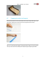
Preparing the bed for its first print
Remove the protection foil from both sides of the acrylic and put blue tape on the
top surface, starting next to the first line that is engraved into the acrylic.
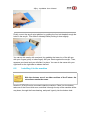
Then run a knife along the length of the groove that is laser cut into the acrylic.
Then you can remove the excess parts of tape and get a really tidy print-bed:
76
3Djoy JoysMaker User Manual
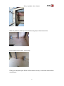
Finally, mount the acrylic print platform by guiding the four bolt heads through the
holes in the acrylic. Then slide it sideways while pushing it down slightly.
You can do this mostly with one hand, by grabbing the lower rim of the left arm
with your fingers (pinky to index finger) and your thumb against the acrylic. Then,
squeeze your hand and you will slide it in place. You can do the same with your
right hand on the right side to release the bed.
6.8
Installing it in the machine
While the pictures are of an older revision of the Z-stage, the
instructions remain the same.
Now the Z-STAGE can be mounted inside the machine. Place it on the bottom,
take one of the 12mm thick axes, and slide it through the top of the machine all the
way down, through the linear bearing, and push it gently into the bottom hole.
77
3Djoy JoysMaker User Manual
Slide the platform a little up and push the axe gently in the bottom hole.
Do the same for the other 12mm axes.
Finally you can place part 3B with 16mm bolts to the top, so the axes cannot slide
out anymore.
78
3Djoy JoysMaker User Manual
Now take the M8 thread and place it from the top into the machine. Screw it into
the nut that is enclosed in the Z-stage and rotate it until it protrudes at the bottom
of the z-stage.
Now you can fix it into the coupling at the bottom by tightening the little set screws.
You need a smaller size Allen key than is currently provided with the machine.
79
3Djoy JoysMaker User Manual
The frame is now ready.
6.8.1
Grease it up
Put a droplet of the supplied tube of grease on your finger and spread it across the
the *leadscrew* by running your finger along its length. Don't grease up any other
rods. Later, when moving the Z axis, the nut will spread it around. You can turn it
by hand now, or let the machine turn it by itself. The volume to add could be less
than 0.5 cubic centimeter, e.g. about the volume of a piece of Sportlife gum.
80
3Djoy JoysMaker User Manual
7
Material feed mechanism
7.1
Contents
[hide]
1 What you'll need
o
1.1 Parts needed in this section
2 Step 1: Assembly of the main body of the drive mechanism
o
2.1 Parts needed in this section
3 Step 2: Drive bolt assembly
o
3.1 Parts needed in this section
4 Step 3: Assembling the clamp
5 What you'll need
o
5.1 Parts needed in this section
6 Step 4: Mounting it to the machine
7 Step 5: Filament holder
o
7.1 Parts needed in this section
8 Questions or comments regarding this page? Let us and others
know!
Click here for a detailed photo series of the construction on our flickr account.
The finished assembly should look like this:
7.2
What you'll need
Time needed:
30-40 minutes (please also report how long it took in the
comments)
81
3Djoy JoysMaker User Manual
Tools needed:
Hex key / driver (2.0mm)
An adjustable wrench (that fits M8 nuts or pliers)
Parts needed in this section
Qty.
Description
Notes
1 Stepper motor
Use the one with the flat part for the small black gear
1 Quick fit coupling
The grey part, used to fit the Bowden tube
2 Bearings
Sealed ball bearings with 8mm inner diameter
A black gear made of Delrin, find it on one of your stepper
1 Small gear
motors
1 Large gear
The large wooden gear
1 Hobbed bolt
This is a bolt with grooves that is used for driving the filament
3 8mm bushing/washer Bushings (or "washers" if you're in the US) used as spacers
12 M3x20 bolts
These are grouped in a bag
1 M3x25 bolts
For the tensioner. These are grouped in a bag
These are special nuts that do not loosen themselves (see
9 Locking M3 nuts
picture)
1 Wooden part 10A
Grouped in a bag
1 Wooden part 10b
Grouped in a bag
1 Wooden part 10C
Grouped in a bag
1 Wooden Gear
Named extruder
Laser
(Delrin)
7.3
cut
parts
These are grouped in a bag
Step 1: Assembly of the main body of the drive
mechanism
Parts needed in this section
Qty.
Description
Notes
82
3Djoy JoysMaker User Manual
1 Stepper motor
Use the one with the flat part for the small black gear
1 Wooden part 10A Grouped in a bag
1 Wooden part 10b Grouped in a bag
1 Wooden part 10C Grouped in a bag
1 Wooden gear
Named extruder
2 Ball bearings 8mm Used in 10A and 10C
1 Quick fit coupling
6 20 mm bolts M3
2 Lock nuts M3
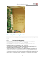
1. Take part 10A and 10C and place the 2 bearings in the corresponding holes.
2. Take the motor with the delrin gear and place part 10A on top of the motor, with
the engraving (10A) facing towards the motor.
3. Take part 10B and place it on top of part 10A.
83
3Djoy JoysMaker User Manual
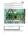
4. Put the quick fit coupling in the T-slot.
5. Place part 10C on top of part 10B.
6. Take 6 20mm bolts and 2 nuts. Use 4 bolts to mount the motor to the parts, but
don't bolt them tight. The motor needs to be adjusted later. Use the other 2 bolts
and nuts to bolt the parts together. These can be tightened normally. If it's not
already there, push the small gear on the motor axis, just until the axis is on the
same level as the front of the small gear. Dont push it further.
84
3Djoy JoysMaker User Manual
7. Take 2 20mm bolts and push them through the holes next to the bearings and
tighten them with 2 lock nuts.
7.4
Step 2: Drive bolt assembly
This section is written for the new drive bolt ('version 3'), for the old
assembly instructions seeDrive_bolt_v2_assembly
Parts needed in this section
Qty.
Description
Notes
1 Big wooden gear
1 M8 nut
1 Drive bolt
3 Washers
1 Delrin clip
Small, black part
1 M8 cap nut
1. Take the drive bolt and click the delrin clip on the groove. Slide it from the motor
side in the bearings, so it protrudes on the other side. The 'good' gripping part
-nearest to the end - should be straight between the two housing plates. If it isn't,
check if you bolted the mounting plates tight enough (but not too tight!).
85
3Djoy JoysMaker User Manual
2. Take the big gear and put the M8 nut inside.
3. place two 8mm washers on the hobbed bolt and then screw on the big gear
(with the 'extrude' text on the outside). The last few turns are easier done by
turning the bolt instead of the gear, because otherwise you are turning the motor
as well. The washers prevent the gear from touching the bolts on the extruder
86
3Djoy JoysMaker User Manual
drive housing. It should not be too tight, the entire bolt and gear should be able to
turn freely in the bearings. Only one washer is shown on the picture.
4. Place a washer next to the gear and then loosely put the (cap) nut on the bolt
5. Tighten the gear and (cap) nut on each other (with the washer in between) If it is
still possible to rotate the gear while the bolt is still, you might need to put another
washer between the (cap) nut and the gear. Tighten the two NUTS together, do
not put the nuts tight onto the hobbed bolt. Withouth filament, the only friction you
should feel is the motor. It is important that the bearings are not clamped together.
There should be a little void/play between the gear-nut and the washers.
87
3Djoy JoysMaker User Manual
The final assembly should have the following order:
Turquoise = Delrin clip
Dark grey = Bearing (in extruder housing);
Blue = M8 washer;
Purple = M8 hex nut;
Yellow = Wooden extruder gear;
Green = Cap nut.
88
3Djoy JoysMaker User Manual
7.5
Step 3: Assembling the clamp
The Extruder Drive Upgrade is a derivative of the design of Bertho's on thingiverse.
It has quite a few benefits over the old one. The facts on the design:
1. Retrofit - fits on all Ultimaker/JoysMaker printers.
2. Spring design - compensate for diameter differences in PLA.
3. The snap system - locks the extruder driver in place, so no more adjusting the
screw.
4. Retraction - this design results in significantly better retraction.
5. Easy assembly - you only have to replace a small part of the extruder not the
whole extruder unit.
6. Noise reduction
Time needed:
About 30 to 40 minutes.
7.6
What you'll need
Parts needed in this section
Qty.
Description
Image
1 30mm M3 bolt
89
3Djoy JoysMaker User Manual
3 25mm M3 bolt
2 20mm M3 bolt
4 16mm M3 bolt
1 nut M3
9 lock nut M3
1 ball bearing 8mm
1 washer M3
1 extruder drive spring
1 push wheel (delrin)
1 extruder mounting plate (delrin)
1 lever (delrin)
1 bracket middle piece (printed)
1 10.1A (4mm plywood)
1 10.1C (4mm plywood)
2 10D (4mm plywood)
90
3Djoy JoysMaker User Manual
Some pictures may show the whole feeding mechanism
disconnected from the Printer, but there is no need to do that
when you're replacing the upgrade.
If you are upgrading your current printer, first do the following:
Use the screwdriver (m3 hex) to unscrew the bolt that holds your old feeding
mechanism in the feeder and take out the Delrin lever as well.
1. Let's start building the new feeding mechanism. First push the ball bearing in
the Delrin wheel. This might require some force, use a piece of plywood to make it
easier to push the ball bearing.
+
=
2. Put a nut in the Delrin Mounting plate at the T-slot. Pay attention that the nut is
placed like in the picture. This will make it easier when you have to put the screw
in on a later stage.
91
3Djoy JoysMaker User Manual
3. Take wooden part 10.1 A and 10.1 C and the Delrin mounting plate. Put them
together using 4 16mm M3 bolts and 4 lock nuts. The engraved letters should be
facing inwards. Make sure the screws enter via the non-engraved side of the 10.1
C wooden part.
92
3Djoy JoysMaker User Manual
Now screw it together with 4 nylock nuts.
4. Next take 2 25mm M3 bolts, 2 lock nuts, the plastic bracket middle piece and
the 2 remaining wooden parts. Put them together as shown in the picture below.
When assembled, the bracket piece can be sticking out partly. You might need to
use some, no excessive, force to put it in its place. Make sure it is leveled with the
wooden parts.
This part should easily fit over the other part you assembled in step 1-4.
5. Take the 25mm M3 Bolt and the delrin push wheel. Insert the push wheel
between the wooden parts 10.1 A and 10.1.C. It fits right into the opening in the
delrin mounting plate. The bolt you use might seem to long at first, but actually it
93
3Djoy JoysMaker User Manual
isn't. Stick it through the wooden parts and the wheel, but don't fully tighten it. The
parts should freely slide over each other.
Then grab the assembled part with the bracket piece, and shove it over the other
part. It should fit right over the bolt. Now you can firmly tighten the lock nut. The
wheel should have a little bit of room for movement and rotating. The assembled
part should be able to move back and forth without friction.
6. Put a spring and a washer over the 30mm M3 bolt and screw this in the back of
the upgrade you have assembled so far. The nut you placed earlier in the delrin
mounting plate should hold the screw in its place. But it still requires some force
because you have to push the spring and screw the bolt at the same time. If you
didn't put the nut in like shown in the picture this might be difficult.
If you think you inserted the nut correctly but are still having problems getting the
bolt in, try removing the spring and reassembling with the bolt barely started into
the nut. You can then compare the how far out the bolt is to the length of the
spring so you have a better idea of how much you need to compress the spring - it
will be about 2-3mm. Reassemble with the spring and try again.
94
3Djoy JoysMaker User Manual
You now have completed the feeding mechanism! Congratulations. Let's attach it
to your printer.
7. If you already removed your old feeding mechanism you can put this new one in
place of the old one. Use the remaining 20mm M3 bolt to connect them both. Do
not screw it on too tight, because it needs to be able to move. Make sure, like with
all other components, that the nuts face AWAY from the wooden gear.
8. You are almost finished, just one step remaining. Since you also have removed
the old lever, you need to replace it with the new one. Notice the difference
between the new and the old lever, the new one is flatter and has only three teeth
per side.
It might look like the old one, but it designed so it locks down. Place it in a way that
the flat side is facing up, when the lever is pushed down.
95
3Djoy JoysMaker User Manual
Great! You just finished upgrading your printer to the next level.
7.7
Step 4: Mounting it to the machine
You can mount it to the frame by sliding it into the slots at the back of the machine
(top left when viewed from the back of the machine). The slots in the middle of the
back plate are for the filament holder.
Put the wires through the hole and through the kite fabric.
Guide the cables from the extrusion head through the hole at the back and
through the cable duct on the inside. Also wrap the wires from the extruder motor
or use a separate piece of coil wrapping.
7.8
Step 5: Filament holder
Parts needed in this section
Qty.
Description
Notes
2 Wooden parts 11B Use the one with the flat part for the small black gear
96
3Djoy JoysMaker User Manual
4 Wooden parts 11C Grouped in a bag
1. Take the two parts 11B and place them next to each other.
2. Put the parts 11C in the corresponding slots of the parts 11B.
3. Place the filament holder in the slots at the back of the machine.
97
3Djoy JoysMaker User Manual
8
Mounting the electronics
8.1
Step 1: What you'll need
Time needed:
About 30 to 60 minutes.
Tools needed:
Hex keys (2mm)
Tiny flat screw driver
Parts needed in this section
Qty.
Description
Notes
5 Socket cap M3 bolts 12mm
Used for installing the electronics.
6 Socket cap M3 bolts 30mm
Used for installing the electronics.
4 Socket cap M3 bolts 10mm
Used for installing the electronics.
7 Hexagonal M3 nuts
Used for installing the electronics.
4 Threaded spacers
White hex squared (color can vary).
4 Tube spacers
White round tubes(color can vary).
1 Circuit board
Green electronic board.
1 Cooling Fan
The big one in the fan pack.
1 Cooling duct sheet
Flat plastic in the fan pack.
1 Wooden panel fan
Flat plastic in the fan pack.
Long squared with a hole for mounting the big
1 Wooden electronic panel
fan.
1 Wooden cover panel
Named "POWER OFF WHEN REMOVED".
1 Blue scotch tape
The blue roll originally inside the Megapack.
1 Black electronics Cabel with 3 tiny This one you need to mount between circuit
98
3Djoy JoysMaker User Manual
plugs on both sides
board and extruder head.
About the electronics
The electronics simply need to be mounted to the machine and a
few wire connectors plugged in. For extra safety, there's also a
cooling system under the electronics that will reduces the chance of
problems. The stepper drivers can get hot, and if they would
overheat, a thermal fuse will turn them off. The cooling system will
allow the machine to work in a warm environment or allow you to set
the current slightly higher than usual.
When handling electronics make sure that you are not statically
charged. This can permanently damage your electronics.
8.2
Step 2: Installing the electronics
Needed in this step
Qty.
Description
Notes
4 Socket cap M3 bolts 30mm Used for installing the electronics.
4 Threaded spacers
White hex squared (color can vary).
4 Tube spacers
White round tubes(color can vary).
1 Circuit board
Green electronic board.
99
3Djoy JoysMaker User Manual
1. On the BOTTOM plate put the 30mm bolts from INSIDE toward OUTSIDE.
2. Put the Tube spacer on the 30mm bolts
3. Put the green circuit board on the 4 bolts.
4. Secure the circuit board on the bolts with the threaded spacers.
Before completely tightening the white threaded spacers, you can slide the bolts
through their slots to decide how much you want to put the electronics towards the
side of the machine. Fixate the circuit board by tightening the threaded spacers.
8.3
Step 3: Preparing the electronics cooling system
Get ready for some serious origami!
100
3Djoy JoysMaker User Manual
Needed in this step
Qty.
Description
Notes
1 Cooling Fan
The big one in the fan pack.
1 Cooling duct sheet
Flat plastic in the fan pack.
1 Wooden panel fan
Flat plastic in the fan pack.
1 Wooden electronic panel
Long squared with a hole for mounting the big fan.
1 Wooden cover panel
Named "POWER OFF WHEN REMOVED".
1 Blue scotch tape
The blue roll originally inside the Megapack.
5 Socket cap M3 bolts 12mm Used for installing the electronics.
2 Socket cap M3 bolts 30mm Used for installing the electronics.
7 Hexagonal M3 nuts
Used for installing the electronics.
You'll be working with the following parts:
1. Mount the fan to the side that is not marked. Use two 30mm bolts and two nuts.
2. Take the cooling duct sheet and fold it along the perforations.
101
3Djoy JoysMaker User Manual
3. Put the cooling duct sheet over the wooden panel and fold the small tabs
downwards to the other side of the panel.
BOTTOM SIDE
TOP SIDE
4. Continue with the bottom (engraved) side facing upwards and place the wooden
air-duct cover over the openings. Fasten it with five 12mm bolts and nuts. Using
short bolts is important so that the ends do not touch the electronics. Make sure
that they are very tight, so that they will not get loose because of vibrations.
5. Put blue tape on the bolt ends to ensure they are isolated electrically, and the
electronics cooling system assembly is finished.
102
3Djoy JoysMaker User Manual
Sealing
If needed, tape the duct sheet to the fan to prevent unwanted air
leaks and to get the most air flow concentrated on the stepper
chips.
Connect the fan to the (always on) 12V power output. The red wire (+ 12V) should
be connected to the + side of the header. When you toggle the power switch, the
fan should turn on (make sure you plug in the power supply too).
Make sure you only have the board powered on when the
cooling system is connected and in place. Otherwise parts may
become very hot. Some parts have an automatic thermal
shutdown, but this doesn't mean you can't burn your hand or
damage other objects.
v1.5.4 through 1.5.7 PCB: connect it there
103
3Djoy JoysMaker User Manual
8.4
Step 4: Connecting the Heater
All the cables inside the machine (printing area) should be
guided through the cable ducts.
1. Connect the white cables of the heater element to two terminals of the HEATER
1 output on the motherboard (the first of the 3 bigger green screw terminals).
Make sure there's not too much wire stripped away so that the one wire touches
the other.
2. Use a small screwdriver to tighten the screw terminals for the heater.
Make sure the wires are connected to the terminals in the
correct way (see picture below).
104
3Djoy JoysMaker User Manual
8.5
Step 5: Connecting the printhead electronics
Needed in this step
Qty.
Description
Notes
1 Black electronics cable with 3 tiny This one you need to mount between circuit
105
3Djoy JoysMaker User Manual
plugs on both sides
board and extruder head.
The black electronics cable with the 3 tiny plugs on both sides will be used for connecting the
circuit board with the extruder head
1. Maneuver the 3 tiny plugs of the black through RIGHT BACK corner of the
machine.
The side with the smaller plugs should be at the print head.
2. Then follow up with guiding the cable through the cable duct and out through
the hole in the BACK (below the motor).
3. Now you are able to connect the plugs to the printhead.
4. Plug the RED/BLACK connector of the extruder head in the BLUE/PURPLE
connector of the black cable.
5. Plug the RED/BLACK/YELLOW connector (with the dot) on the white connector
of the extruder head (tiny circuit board).
6. OPTIONAL: plug the GREEN/ORANGE/BROWN connector on the second
connector.
7. When you are done, you are ready to connect the cables at the bottom of the
machine.
Positions of the connectors
At the bottom of the machine you see engraved in the wood the
position where you need to plug in the connectors.
106
3Djoy JoysMaker User Manual
8. Plug the BLUE/PURPLE connector on the circuit board where is says FAN
PRINTHEAD.
9. Plug the RED/BLACK/YELLOW connector on the circuit board where is says
TEMP1
10. Plug the GREEN/ORANGE/BROWN connector on the circuit board where is
says TEMP2
8.6
Step 6: Connecting the rest of the cables
To prevent problems later you need to guide all the cables
through the cable ducts. Make sure that you guide the cables
the shortest way down to the bottom of the machine. Any loose
cables inside the machine (printing area) can cause trouble.
1. The connect the limit switches to the circuit board where is says END STOPS.
The limit switches each have a number (e.g.
), listed next to the limit-switch
itself and listed where the header for this limit-switch is located.
8.6.1
Tracing back cables limit switches
The black limit switch that is connected at the BOTTOM plate is limit switch
number 1.
The black limit switch at the TOP of the machine is limit switch number 2.
The Red limit switch at the BACK of the machine is limit switch number 3.
The Red limit switch at the FRONT of the machine is limit switch number 4.
The Blue limit switch at the RIGHT of the machine needs to be placed where it
says FRONT RIGHT.
The Blue limit switch at the LEFT of the machine needs to be placed where it says
FRONT LEFT.
107
3Djoy JoysMaker User Manual
8.7
Step 7: Connecting the motor
2. You now can connect the 4 motors to their respective connections on the circuit
board.
8.7.1
Tracking back cables motors
The X-MOTOR is connected to the BACK of the machine and needs to be
connected at the circuit board where is says X-MOTOR.
The Y-MOTOR is connected to the LEFT of the machine and needs to be
connected at the circuit board where is says Y-MOTOR.
The Z-MOTOR is connected tot the BOTTOM of the machine and needs to be
connected at the circuit board where is says Z-MOTOR.
The EXTRUDER-MOTOR is connected to the BACK (outside) the machine and
needs to be connected at the circuit board where is says EXTRUDER-MOTOR.
3. Optional is to connect a 24V led strip (some were supplied with the very first kits)
directly the 19V of the power supply. Alternatively, if you want the LED's to blink
108
3Djoy JoysMaker User Manual
while extruding, you can connect it in parallel with one of the extruder motor phase
(output 1/2, or output 3/4 of extruder 1).
4. If you have a JoysMaker controller, now is a good time to assemble it and
connect it to the electronics. This will save you some time later on, as you don't
need to remove the cooling system again.
5. When your circuit board looks like the one shown below, you can safely mount
cooling system as written in Step 3.
8.8
Step 8: Installing the electronics cooling system
Needed in this step
Qty.
Description
Notes
4 Socket cap M3 bolts 10mm Used for installing the electronics.
1. Insert the 10mm bolts into the white threaded spacers, but not all the way.
2. Place the cooling assembly over the bolts, guiding them through the larger
holes.
109
3Djoy JoysMaker User Manual
3. Slide the part in place to lock it.
4. Insert the bolts slightly more so that they touch the wood.
8.9
Step 9: Strain relief
Picture by Bernhard
110
3Djoy JoysMaker User Manual
1. Wrap the black cable, bowden cable and the white cables of the heater together
in transparent wire wrapping to get a tidy cable.
2. At the bottom you should wrap the electronic cables together with the velcro
strips.
3. The cables inside the transparent wire wrapping should go through a strain
relief at the extruder end.
The black F-shaped part that is bolted on top of the extruder housing, can be used
to wrap the thin wires through.
This will ensure that if you pull the cable, it will not put strain on
the crimped connections in the connector, but instead put the
strain on the F-shaped part.
8.10
Step 10: Checking and aligning the Z-homing switch
This is the MOST important end-stop of the system. It is
important that the starting height of your machine is about
0.1mm above the platform, and especially important that it
doesn't start after digging INTO the platform.
Start by leveling the bed.
1. Turn the Z-leadscrew until the the extruder head is almost touching the
build-platform.
2. Move the printhead to the front left corner.
3. Turn the adjustment bolt up until it touches the platform.
4. Screw DOWN the front right of the platform until you can move the print head to
the right side of the platform without scratching the platform.
5. Then turn it up slightly until it also touches the platform.
6. Repeat this process for the adjustment bolts in the back.
Your platform's plane should now be exactly parallel to the XY-plane. Now it's
time to adjust and TEST the Z-switch.
1. The top Z-switch in the back (with black wires) is for homing the platform until
the platform is elevated to the 'zero' position. Zero means, no distance between
the platform and print-head. It should already be installed.
2. Loosen the bolts slightly so you can move it up and down.
3. Turn the lead screw to elevate the platform until the head almost touches the
platform.
4. Now lower the endstop and fasten it slightly on one side, while still being able to
111
3Djoy JoysMaker User Manual
slide in the other slot. Sliding the 'free side' means that you're rotating the switch a
little bit.
5. Rotate it until it the switch click in the closed position.
6. Then fasten the other side slightly. If it doesn't click yet, that's okay, just lower
the other bolt of the switch until it clicks.
7. Check the Z-position when it clicks the switch to the closed position. Where it
clicks open again is not as important, as long as it doesn't stay closed.
8. Fasten both bolts fully. They're allowed to sink into the wood slightly, the switch
shouldn't move anymore.
When you're using the control software for the first time, test
the response to the limit switches, especially the Z-homing
switch.
8.11
Troubleshooting the mechanics
Please interact through the forums at Ultimaker.com/community. Please also have
a look at theTroubleshooting the mechanics page.
8.12
What's next?
Congratulations! You now have a complete 3D printer. Learn how to use your
printer by starting with the Cura software setup:
112
3Djoy JoysMaker User Manual
9
9.1
Software setup guide
Setting up the JoysMaker 3D printing software
This guide will help you setup your printer. Cura is the JoysMaker supported piece
of software. NetFabb is another option, it is a fast and professional slicer with
many advanced features. Both Cura and NetFabb allow you to process a 3D
model into a printable file, and printing this file directly on your machine (direct
connection). Cura will automatically detect your machine and will work faster and
produce better quality prints. You can process the file with Cura or NetFabb and
then copy the file onto the SD card which goes into the UltiController. You can
then print the model without a connection between the PC and JoysMaker. In
NetFabb, the direct connection will not always work, so the UltiController option is
strongly recommended for printing in conjunction with NetFabb.
In this step we be installing the Cura and begin to use it.
9.2
Contents
[hide]
1 Setting up the JoysMaker 3D printing software
2 Download
3 Documentation
4 Using Cura
5 Preparing a model file for printing
6 Troubleshooting
7 Linux Dependencies
8 Guides in other languages
9 Advanced features
10 Questions or comments regarding this page? Let us and others
know!
113
3Djoy JoysMaker User Manual
Category: Software
Cura is developed by Ultimaker to make 3D printing as easy and streamlined as
possible. It includes everything you need to prepare a 3D file for printing and to
print it. Cura is fully preconfigured to work on the Ultimaker. Cura comes with a
friendly setup program that help you install the latest firmware as well as calibrate
your printer. JoysMaker is compatible with Ultimaker.
9.3
Download
The latest version for Windows, Mac and Linux can always be found at
the Ultimaker software downloads page.
9.4
Documentation
Main documentation for Cura can be found at GitHub: GitHub
9.5
Using Cura
Installing Cura is very simple. Click the version required by the system you run,
unpack it and you are ready to go.
9.6
Preparing a model file for printing
Now, I assume you have a 3D model you want to print. Otherwise, you can get
one from Thingiverse. Cura converts model files (such as .STL files) to read this
file and convert it into GCode. GCode are the movement instructions for your
printer. Use the "Load model" button to load an view your 3D model. Then use
"Prepare print" button to start the creation of the GCode file. This will take a while,
114
3Djoy JoysMaker User Manual
and when the progress bar is done, you can go to the next step. You can then
print through USB, or place your GCode file onto the SD card with the click of a
button!
You can print with lower temperatures than 230C, but
temperatures between 210 to 230C are a good starting point.
You can start lowering the temperature after printing with
success. Note that lower temperatures could cause problems,
especially at high printing speeds.
9.7
Troubleshooting
Installing Cura on Linux has a few caveats. Check out installing Cura on Linux.
If Cura doesn't work for you, then goto the Ultimaker Forums for help.
9.8
Linux Dependencies
For an Ubuntu distribution, you will also need to install the following
dependencies:
sudo apt-get install python-setuptools python-numpy
python-scipy python-wxgtk2.8 python-wxtools wx2.8-i18n
libwxgtk2.8-dev libgtk2.0-dev
You will also need to install python dependencies (how to install pip):
pip install PyOpenGL PyOpenGL_accelerate pyserial numpy
And one module not available via pip;
https://github.com/GreatFruitOmsk/Power
If you are on Ubuntu 12.04, you may need to add wx to the python path:
export
PYTHONPATH="$PYTHONPATH":/usr/lib/python2.7/dist-packages/wx
-2.8-gtk2-unicode
115
3Djoy JoysMaker User Manual
10 Troubleshooting
10.1
10.1.1
Problems by observation
Printing in material A worked fine, now material B doesn't
print well!
See the section on
problems".
10.1.2
Polymers
and "Troubleshooting: Solving flow related
Brown sludge forms on the extruder head
If your printer came with an ABS Fix Kit (a piece of ABS filament), running this
through the extruder will seal up any small leaks around the printer head. If for
some reason you did not get this kit, any piece of 3mm ABS filament will do.
10.1.3
Plastic comes out of extruder head in a flowing state
If you turn the big extruder wheel manually, the plastic exiting the extruder head
should form a thin line of plastic that hangs from the extruder head. If however the
plastic does not form this thin line, but rather forms a droplet at the extruder head,
you are heating the plastic too much.
Be careful. Too high temperatures can cause the plastic to burn and form a plug.
In general, start at 215C for PLA plastic and 225 for ABS plastic.
10.1.4
The extruder stops extruding
There are several possible causes for this:
You are trying to extrude when the extruder is still cold. There is a pre-build
function in Marlin that prevents cold extrusion. It could also be because of a
failure. Please check the warning log.
You're trying to extrude too much material in a small volume. Try to print a
really thin walled object. If these objects work well, but a large infill doesn't, it
shows you that the extrusion rate is too high.
The temperature at which you're extruding material needs to be high
enough. If you've just switched materials, e.g. from ABS to PLA, you need to
extrude at the ABS temperatures to flush out the ABS. This may take quite
some printing to get the last remains of ABS out of the extruder. Using
temperatures that are normally suitable for PLA might jam the extruder if
remains of ABS try to work their way through the nozzle. PLA can be printed at
temperatures between 190 and 260 degrees C. At 250 degrees it will flow
fairly easily. Above this temperature it might become too liquid and the nozzle
might ooze too much.
116
3Djoy JoysMaker User Manual
You're trying to extrude too fast. Try to lower the feed rate. PLA in general
flows more easily than ABS. ABS will start to degrade when you heat it up too
much, and might block the nozzle's orifice when it sits in the extruder for a long
period of time. Heating it to a higher temperature in general allows you to print
at the higher speeds.
Possibly, liquid PLA is pushed upward in the extruder to a section where no
heating is applied. When this solidifies, it causes the extruder to jam.
Especially if there is a small gap between the PFA/PTFE tube and the brass
part of the extruder, this will cause the plastic to be very hard to push through.
Normally, the (low friction) bowden tube has such a low friction that you can
still push out the solidified PLA with some force.
When the extruder has jammed, the material-feed mechanism may
continue to push material into the extruder. When that is blocked it will apply a
large force on the bowden tube, causing it to come loose from the metal part of
the extruder. After a while it will pull the connectors from the thermocouple
board. Soon afterwards the extruder will overheat as the temperature
feedback has been severed. Immediately disconnect the power when the
bowden tube comes loose.
Apart from these hints, it's always good to heat up the extruder, and to try to push
the filament in by hand. It should be possible to push it in with reasonable force.
First see if the temperature you're setting it to is appropriate for the material that
you're using. PLA becomes fairly liquid at around 250 degrees. Below this
temperature it is still pretty viscous and becomes more difficult to extrude.
See also:
Solving flow related problems
How to remove PLA when blocked and hack the PTFT cable
10.1.5
The first layer doesn't stick!
This is a common problem because all thermoplastics vary. Even if you're using
PLA, one color of thermoplastic may stick perfectly while another color does not
stick at all: this is because the colorants affect the melting point, also shift the
recommended print temperatures.
If you have trouble getting the first layer to stick, you can do several things:
Make sure the print head is almost touching the platform for the first layer.
This helps because the plastic is really pushed into the texture of the blue tape.
This will also help with the pressure build up before you print. Don't hesitate to
do a small adjustment by turning the Z-leadscrew by hand just after your print
has started. If this works better, you can make this permanent by changing the
height of the Z-limit switch at the back of the machine (the top one).
117
3Djoy JoysMaker User Manual
Just when the print starts, you can turn the extruder-drive's gear a little to
get increase the material flow for the first layer. This helps for the same
reasons mentioned above. Don't worry, you will not damage the motor by
pushing it through its steps, it will just skip a few steps which is totally
harmless!
If you're printing directly onto the acrylic platform, sanding and/or
scratching the acrylic will help to create a stronger bond.
Try raising your extrusion temp a few degrees, even bumping the print
temp by 5 degrees or so can really make a difference.
Ensure that the bed is level. If it isn't level, this will create a good bond in
one place, but the head will be too high in the other.
For the first layer, during printing you can increase the 'flow rate' through
the Real Time Tuning feature (by clicking the icon with the sliders). Slide it
back to 100% when the first layer has finished.
Sometimes the tape is greasy, this makes it hard for the PLA to stick on it.
Cleaning it with some rubbing alcohol removes the grease and makes the PLA
stick easier.
10.1.6
My 3D prints do not look good!
Analyzing your first print (a great post by Florian on his blog)
Check if the fan (near the print head) turns on after the first layer has
printed. If you can turn it on with the control panel, it's wired up correctly. If not,
check the wiring. Also check your Skeinforge profile's "Cool section". If an
M107 code is in the G-Code, this means that the fan SHOULD turn on.
Problem: layers aren't stacked very well on top of each other
Solution 1: make sure your long belts are tight enough (see this instruction
video).
Solution 2: check if the short belts are tight, if not, slide down the motor in
its slots and re-tighten them. You probably need washers to tighten it all the
way.
Solution 3: if too much plastic is extruded, it will try to find its way out of the
extruder where it shouldn't be. Lower the extrusion rate.
Solution 4: if too little plastic is extruded it will take shortcuts, the following
layers may not stick to the layer below, because parts of that layer aren't
where they're supposed to be. Increase the extrusion rate.
Solution 5: check if your object has enough time to cool before the next
layer. If you print an object with a thin cross section very fast, it will not have
118
3Djoy JoysMaker User Manual
time to cool. Slow down your print speed. You can force a layer to always take
a certain amount of time, this is done in the "Cool" section of your Skeinforge
profile. Also, ensure that the "Turn fan on" checkbox is ticked there and that
the fan indeed turns on!
Problem: the object looks sparse, there are holes in them! (see
picture on the right)
A very sparse print
The problem is that too little plastic is extruded. This can have several causes,
each cause requires a different approach to solve it.
The causes and solutions are discussed in:
related problems.
10.2
10.2.1
Troubleshooting: Solving flow
Mechanical problems
X/Y axis
The extruder head stops moving during a print, or doesnt move
at all (even in manual mode). Also a stuttering or grinding noise
can be heard from the stepper motors.
This is caused by a stepper motor driver that is too cold or overheating. Try to tune
the stepper motor driver to a more ideal setting. You can find a manual about the
stepper motor driver in the Electronics build guide.
There is a lot of friction when I move the extruder head around by
hand. What can I do?
119
3Djoy JoysMaker User Manual
First, check if you accidentally used square nuts for the caps that hold the rods captive (on the
inside of the frame).
When moving the head by hand, do it by pushing the wooden blocks in ends of the
rods. Pushing directly on the print head assembly twists the bushings and causes
them to jam. This might give the illusion that there is more friction than there
actually is.
The important thing to keep in mind is that all angles need to be orthogonal (90
degrees), not 95 or 85 degrees... The best way to achieve that the crossing rods
are orthogonal is to loosen pairs of pulleys. You don't need to open the jaws of the
blocks where the timing belt passes through, this is too tedious and the same
result is achieved by loosening the pulleys.
Usually it is easier to ensure they are orthogonal by putting an axis (X or Y) near
its end, and to compare the distance between the blocks. For the X axis (left to
right if you stand in front of the machine), it is important to keep both blocks at
about the same distance.
Very rarely, it seems that it runs slightly more smoothly when it's not orthogonal,
but both crossing rods have an odd angle but exactly to same extent. This would
lead to slightly trapezoid prints which are no good for prints that need to be
mechanically accurate. Perhaps it's good to loosen the bolts of the wooden
extruder housing and tighten them with the extruder housing after it has been
installed in the machine.
Don't grease the rods! All bearing in the JoysMakers are self-lubricating! Use the
teflon-based grease ONLY for the Z spindle. That's where it belongs.
An example of barely touching outer line. Click on the picture to see more details and
120
3Djoy JoysMaker User Manual
annotations on the image.
When a layer is printed, the perimiters and infill of the object do
not or barely touch. How can I fix this?
Ensure that the motors have cooled down before you press on
the motor, otherwise you risk getting burns.
This could have a mechanical and a software cause. The software should ensure
that the perimeter and infill overlap slightly. This part is about the mechanics: One
thing that could cause this (a bit) would be too loosened motor timing belts (the
two short belts). If the X axis has this problem, you'll see gaps at the left and right
side between the perimiter and infill. If the Y axis has this problem, it will happen at
the front and back of your print (when looking at the front of the machine). To fix
this problem, loosen the four bolts, push the motor down firmly and hold it that way
while fastening the motor bolts. Make sure you wait a while for the motors to cool
down.
This problem can also be caused by loose belts, especially the short ones. For the
long belts, see thisinstruction video.
10.2.2
Z-axis
The object doesn't have the correct height
If the object is longer or shorter, the Z-axis may have too much friction.
Observation A: The height is exactly twice as big/small
Check the jumper configuration correspond with the intended
settings in the guide (for those with the 1.5 PCB version. If you don't have
jumpers on your electronics, this isn't the problem).
Observation B: sometimes the platform lowers less than it should
Solution 1: lubricate the leadscrew (along its entire operating length),
if that doesn't help, increase power to the z-motor.
Solution 2: If that doesn't help, see if the Z-axis is trying to move too
quickly. You can set a limit in your Skeinforge profile (under Limits).
Solution 3: Check if the top end-stop is being triggered at random
intervals by electromagnetic interference (EMI). How? If the problem is
gone with the top Z-home limit-switch detatched, it was EMI. Twist the
wires or (still not enought?!) shield the wires if this is causing it.
121
3Djoy JoysMaker User Manual
The object seems to have ripples in the Z-axis
The machine is depositing plastic, so it will always have ripples. However, there
are several cases that can cause irregular behavior:
If the printhead is not levelled out correctly, the print will deposit more on
one side then the other, causing it to ripple or even warp prematurely.
If the printhead is level but the print looks shakey, it can be caused by
several problems:
The Z-axis rod may have bent during shipping.
The Z-axis rod is not correctly seated in the aluminium holder.
The print is warping while printing, or has come loose on several
parts.
10.3
Electrical problems
Nothing happens when I toggle the ON switch
If your machine suffered a short circuit the power supply (PSU) might have shut
down itself as safety measure. What to do: Disconnect the PSU from the wall
socket and the printer this lets it reset. Reconnect and try the ON switch again.
122