1
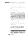
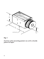
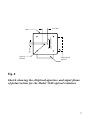
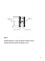
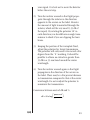
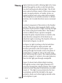
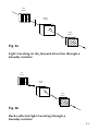
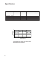
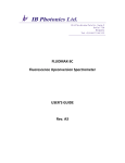
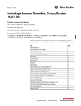
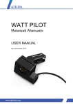
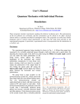
Model 556X User’s Manual Optical Isolator 550031 Rev. A 2 Is a registered trademark of New Focus Inc. Warranty New Focus, Inc. guarantees its products to be free of defects for one year from the date of shipment. This is in lieu of all other guarantees, expressed or implied, and does not cover incidental or consequential loss. Contents Warranty 3 Quick Start 4 Operation 5 Theory 13 Specifications 14 3 Quick Start Feedback into lasers from back reflections can cause power and wavelength fluctuations and in extreme cases can damage the laser. Our Faraday optical isolators give you greater than 35-dB peak isolation and 25-dB minimum isolation over more than 20 nm without having to make any adjustments. The isolator is shipped ready to use and optimized for operation at the center wavelength. Simply mount the isolator on the pad provided so that the polarization plane of your laser is aligned with the minor axis of the elliptical aperture. See figure 2 on page 7 for more information. An adjustable output polarizer and a zero-order half-waveplate are included at the isolator output. The adjustable output polarizer allows you to optimize the isolation at any wavelength within the isolators range (see page 10). The zero-order halfwaveplate gives you complete flexibility in output polarization orientation over a broad band of wavelengths. 4 Operation As shipped, the isolator is adjusted for optimum isolation at the center wavelength and is ready to use. Caution: The magnetic field around the isolator will grab tools and components. Use care when mounting the isolator and protect the optical surfaces. Mounting the isolator The isolator can be used with either vertically or horizontally polarized light. For vertically polarized light, mount the isolator on the pad provided so that the label is on the top (as shown in Figure 1). For horizontally polarized light, mount the isolator on the pad so that the label is on the side. For most laser diodes the plane of polarization is along the minor axis of the beam’s ellipse. Therefore, the elliptical aperture of the isolator will coincide with the elliptical laser beam profile for the majority of laser diodes.* (Shown in Figure 2) For more detailed information about polarization and polarization control ask for a free copy of our Application Note 3. The mounting pad provides a one-inch beam height and an 8-32 (M4) threaded hole, that allows mounting to our pedestal risers or half-inch * Some strained laser diodes may be polarized along the major axis of the beam's ellipse. In this case the major axis of the beam must be reduced to less than 3 mm to clear the isolator aperture. See page 98 of our 95/96 catalog for details of our circularizing prism pairs. 5 1.75 " (44. 4) N IN Opt EW F C ical OCU Mo enter Isol S, I del: Wa ato nc. #55 vele r n 68 gth : 85 0nm Ma OUT de i nU SA 3.24 " (82. 4) mounting pad 1.00 " (25. 4) Fig. 1 Position of the mounting pad for use with vertically polarized input. 6 .316" (8.0) elliptical aperture plane of polarization .118" (3.0) label mounting pad positions Fig. 2 Sketch showing the elliptical aperture and input plane of polarization for the Model 556X optical isolators. 7 posts. An adapter plate, Model #5560, is available which attaches the isolator kinematically to our 6200 series external-cavity diode laser. Adjusting your isolator The output polarizer and waveplate are mounted in rotating knobs that you can adjust as required. Both the polarizer and waveplate can be locked in position using the locking screws shown in Figure 3. The output polarizer has ± 10˚ of adjustment and can be used to peak up the isolation at specific wavelengths (see the next section). Light which exits through the output polarizer is normally polarized at 45˚ relative to the input polarization plane. A zero-order half-waveplate, which can be rotated through 360˚, allows you to rotate the plane of polarization to any desired orientation. The optical axis of the waveplate is marked with the symbol “ ”. The “||” mark indicates the waveplate orientation for the input and output polarization planes to be parallel. The “ ” mark indicates the waveplate orientation for the input and output polarization to be perpendicular. 8 waveplate locking screw polarizer locking screw polarizer holder waveplate holder Fig. 3 Output polarizer and waveplate holders showing the position of the locking screws. 9 To maximize the isolation at a specific wavelength The polarization rotation of the Faraday rotator is wavelength dependent and so 45˚ rotation only occurs at the center wavelength. As the polarization rotation changes, the isolation decreases because the polarizers are no longer aligned for extinction of back-reflected light. Your isolator will give you isolation of more than 25 dB over a 20-nm band around the center wavelength with no adjustments. (see graph on page 14) The isolator can be used over a 35-nm range around the center wavelength by using the output polarizer to peak up the isolation. In fact you can peak the isolation up to 35 dB at any single wavelength over this 35-nm range. This may cause a few percent decrease in the transmission. The half-waveplate we supply is zero order which means it performs well over a broad band of wavelengths. However, if linear polarization is critical to your experiment, you will need an additional polarizer after the isolator because the waveplate may produce slightly elliptical polarization at extreme wavelengths. 1) Mount the isolator on the pad to correspond with your input polarization state, as discussed in the previous section. Set the polarizer to the “0” mark and the waveplate to the “||” mark (remember to loosen the set screws first). Monitor the transmission through the isolator using an optical detector. Check that the background light level is more than 45 dB below 10 your signal. It is best not to move the detector before the next step. 2) Turn the isolator around so that light propagates through the isolator in the direction opposite to the arrows on the label. Monitor the amount of light transmitted through the isolator, which will be very small (-35 dB of the input). By rotating the polarizer 10˚ in each direction you should have enough transmission to check if you are clipping the laser beam. 3) Keeping the position of the waveplate fixed, adjust the polarizer for lowest transmission. The polarizer will only need to be moved a few degrees from the “0” marking. It should be possible to obtain an extinction greater than 35 dB in a 35-nm band around the center wavelength. 4) Turn the isolator around again so that light propagates in the direction of the arrows on the label. There may be a few percent decrease in transmission compared to that at the center wavelength. Do not readjust the polarizer to maximize the transmission. Conversion between units of dB and %. power out dB = 10 x log power in 11 Theory Optical isolators work by allowing light to be transmitted through the isolator in the forward direction but blocking back-reflected light. The #556X series optical isolators consist of four main components; an input polarizer, a Faraday rotator, an output polarizer and a zero-order half-waveplate. The waveplate is not actually necessary to achieve isolation, but it makes the device more convenient to use. A critical component of the isolator is the Faraday rotator. This uses a static magnetic field to rotate the plane of polarization of light traveling through the rotator using the Faraday effect. The Faraday rotator is different from a quarter waveplate because the plane of polarization is rotated in the same direction irrespective of the direction in which the light is traveling. The benefits of this are illustrated in Figures 3a and 3b. In Figure 3a light traveling in the forward direction passes through the input polarizer and becomes polarized in the vertical plane. Upon passing through the Faraday rotator, the plane of polarization is rotated 45˚ due to the static magnetic field around the rotator. The output polarizer, which is aligned 45˚ relative to the input polarizer, then lets the light pass through unimpeded. Figure 3b shows back-reflected light traveling through the isolator. Only light polarized at 45˚ can enter through the output polarizer. The rotator material rotates the plane of polarization an additional 45˚. The light is now polarized in the horizontal plane and will be blocked by the input polarizer, which only allows light polarized in the vertical plane to pass. 12 input polarizer Faraday rotator 45° output polarizer Fig. 4a Light traveling in the forward direction through a Faraday isolator. input polarizer Faraday rotator 45° output polarizer Fig. 4b Back-reflected light traveling through a Faraday isolator. 13 Specifications Model # 5566 5567 5568 5569 Center Wavelength 670 nm 780 nm 850 nm 980 nm Peak Isolation 35 dB 35 dB 35 dB 35 dB Min. Isolation 25 dB 25 dB 25 dB 25 dB Wavelength Range 20 nm 20 nm 20 nm 20 nm Min. Transmission 80% 80% 80% 80% Damage Threshold 50 W/cm2 50 W/cm2 50 W/cm2 50 W/cm2 Input Polarization vert. or horiz. vert. or horiz. vert. or horiz. vert. or horiz. Output Polarization user variable user variable user variable user variable Isolation (dB) 50 40 30 20 10 0 840 845 850 855 860 Wavelength (nm) Typical isolation for a Model 5568 Faraday isolator without making any adjustments. 14 Notes 15 16