1
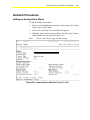
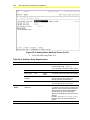
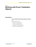
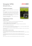
N30 Supervisory Controller User’s Manual
26-1
Chapter 26
Working with Analog Alarm
Objects
Introduction
The Analog Alarm object adds the alarming capability for a
floating-point attribute of any object, such as the Present Value of an
Analog Input object.
Note:
The Input Reference of an Analog Alarm object should refer
to an analog attribute type in order to perform as intended.
Analog Alarm objects referencing other attribute data types
(e.g., Boolean) yield unusual results, though not necessarily
unusable results. Neither the VT100 nor Project Builder give
an error message when this object is attached to any attribute
other than floating point based attributes.
This object detects an alarm based on up to four limits and can be
configured to report that alarm. This object sets the Alarm State
attribute of the object it is added to.
This chapter describes how to:
•
add an Analog Alarm object
•
edit an Analog Alarm object
•
command an Analog Alarm object
•
delete an Analog Alarm object
© November, 2001 Johnson Controls, Inc.
Code No. LIT-6892260
www.johnsoncontrols.com
Software Release 5.0
26-2
N30 Supervisory Controller User’s Manual
Key Concepts
Analog Alarm Object
When the Analog Alarm object’s Input attribute value exceeds the
defined limits, it causes a change in the Analog Alarm object’s present
value and the generation of a Status Notification Report (SNR).
For example, with this object you can have a warning issued if the
temperature in a room falls below 60°F and an alarm issued if the
temperature falls below 50°F.
States
The Analog Alarm object can be in any of the following states:
Normal State
This occurs when the Analog Alarm object is in an acceptable,
expected condition, as indicated by the Input attribute value.
Off Normal State
This occurs when the Analog Alarm object transitions into the high
and low warning conditions, as indicated by Input attribute value.
Fault State
This occurs when the Analog Alarm object transitions into the
high alarm, low alarm, and unreliable conditions, as indicated by the
Input attribute value.
SNR
Status Notification Report. A report that is generated by alarm
objects and routed via the Message Routing feature to printers and
VT100 Terminals.
N30 Supervisory Controller User’s Manual
26-3
Attributes
The values of an object’s attributes determine how the object operates.
The Analog Alarm object attributes described below are listed in the
order that they appear on the screen. Entry requirements for these
attributes are in Table 26-2.
For additional information about the Analog Alarm object and its
attributes, refer to the Object Dictionary.
Object Name
Identifies the object on the user interface.
Description
Provides optional information to further describe the object.
Object Type
Indicates the kind of object, such as Schedule, N2 Analog Input, or
Analog Alarm.
Object Category
Determines the general classification of an object to help define user
access capability and message routing.
Enabled
Indicates if the object is active and executing an operational condition.
Input Reference
Indicates the object and attribute monitored for Changes-of-Value
(COVs) and reported in alarm messages. The reliability of the Input
Reference is monitored and saved in the Reliability attribute of this
alarm object. The last value received from the Input Reference is
written to the Input attribute.
High Alarm Limit
Specifies the actual High Alarm Limit. If blank, the limit is not used.
Low Alarm Limit
Specifies the actual Low Alarm Limit. If blank, the limit is not used.
26-4
N30 Supervisory Controller User’s Manual
Differential
Indicates the amount the Input decreases or increases. If the Input is in
High Alarm (or High Warning), it must decrease by the Differential
before the object will return to High Warning (or Normal). If the Input
is in Low Alarm (or Low Warning), it must increase by the
Differential before the object will return to Low Warning (or Normal).
This Differential is provided to prevent nuisance alarms due to a value
that is cycling near an alarm (or warning) limit.
High Warning Offset
Indicates the value that is added to the Analog Alarm Reference
attribute to determine the actual High Warning Limit. If blank, the
offset is not used. Either the High Warning Offset and Low Warning
Offset must be defined or both must be blank.
Warning Reference
The value that is added to the High and Low Warning Offsets to create
the actual warning limits that the Input is compared against. The
Reference is typically a setpoint. In order to disable warning analysis,
this attribute must be blank.
Low Warning Offset
Indicates the value that is subtracted from the Analog Alarm Reference
variable to determine the actual Low Warning limit. If blank, the offset
is not used. Either the High Warning Offset and Low Warning Offset
must be defined or both must be blank.
Fault Ack Req (Acknowledgment Required)
Indicates whether a transition into the Fault state creates a Message
Requiring Acknowledgment (MRA).
Fault Priority
Provides the priority assigned to the Fault state that gets transmitted to
the SNR.
Fault Ack Pend (Acknowledgement Pending)
Indicates whether a Message Requiring Acknowledgment (MRA)
concerning a transition into the Fault state is waiting to be
acknowledged.
Off Normal Ack Req (Acknowledgement Required)
Indicates whether a Message Requiring Acknowledgment (MRA)
concerning a transition into the Off Normal state must be
acknowledged.
N30 Supervisory Controller User’s Manual
26-5
Event Enable
Determines if the object sends reports (SNRs), if this value is True.
Dialout Required
Forces a dial out to a destination device (if True), when this object
goes into an alarm or warning state.
Delay Time
Indicates the amount of time, following a change to the Analog Alarm
reference value, that an Input must get within the warning or alarm
limits before the object reports the warning. After this time, the input
value is reevaluated. If it is still outside of the limit, a report is
generated. If the Delay Time is changed, any current timer is canceled
and reset to the new Delay Time.
Off Normal Priority
Indicates the priority assigned to the Off Normal state that gets
transmitted to the SNR.
Normal Ack Req (Acknowledgement Required)
Indicates whether an MRA concerning a transition into the Normal
state must be acknowledged.
Normal Priority
Indicates the priority assigned to the Normal state that gets transmitted
to the SNR.
Alarm Message Text
Provides text associated with the SNR that a user can add for further
information when an alarm or warning occurs.
26-6
N30 Supervisory Controller User’s Manual
Procedure Overview
Table 26-1: Working with Analog Alarm Objects
To Do This
Follow These Steps:
Add an Analog Alarm Object
Browse to and highlight the container or object where the Analog Alarm
object is to be added. Press the F3 (Add) key. Highlight Analog Alarm
and press Enter. Fill in the fields using Table 26-2. Press the F3 (Save)
key. Check the User Assistance area of the screen to verify if the save
was successful or if there were errors. Press any key to continue. Press
the F4 (Cancel) key to return to the container hierarchy.
Edit an Analog Alarm Object
Browse to and highlight an Analog Alarm object. Press Enter to open the
object. Press the F3 (Edit) key. Edit the fields using Table 26-2. Press the
F3 (Save) key. Check the User Assistance area of the screen to verify if
the save was successful or if there were errors. Press any key to
continue. Press the F4 (Cancel) key to return to the container hierarchy.
Command an Analog Alarm
Object
Browse to and highlight an Analog Alarm object. Press the
F2 (Command) key. Use the Spacebar and the Backspace key to cycle
through the list until the desired command appears. Press Enter.
Delete an Analog Alarm Object
Browse to and highlight an Analog Alarm object. Press Enter to open the
object. Press the Delete key. Press the Tab key to confirm the deletion.
N30 Supervisory Controller User’s Manual
26-7
Detailed Procedures
Adding an Analog Alarm Object
To add an Analog Alarm object:
1.
Browse to and highlight the container or object where the Analog
Alarm object is to be added.
2.
Press the F3 (Add) key. The Add Object list appears.
3.
Highlight Analog Alarm and press Enter. The first of two Analog
Alarm attribute screens appears (Figure 26-1).
Note:
Use the [ and ] keys to page to other screens.
Figure 26-1: Analog Alarm Attribute Screen (1 of 2)
26-8
N30 Supervisory Controller User’s Manual
Figure 26-2: Analog Alarm Attribute Screen (2 of 2)
4.
Fill in the fields using Table 26-2.
Table 26-2: Attribute Entry Requirements
Screen Area
Attribute
Required
Default
Options/Range
Object
Object Name
No
Blank
Maximum 32 characters
Invalid characters: @ . ? * $ # : ’ [ ]
If not completed, the system assigns a name.
Description
No
Blank
Maximum 40 characters
Object Type
Yes
Analog
Alarm
The default is preset and cannot be changed.
Object
Category
Yes
HVAC
Use the Spacebar and Backspace key to
view and select options: HVAC, Fire,
Security, Services, Administrative.
Enabled
Yes
True
Use the Spacebar and Backspace key to
view and select options: True, False.
Input
Reference
Yes
Blank
If this Analog Alarm object is being added to
a container, the exact name of the object and
attribute to have an alarm must be entered. If
this Analog Alarm object is being added to
another object, the name of that object
appears automatically with its Present Value
attribute.
Example: HEATING SP.Present Value.
Present Value is the default attribute that
appears.
Engineering
Values
Continued on next page . . .
N30 Supervisory Controller User’s Manual
26-9
Screen Area
(Cont.)
Attribute
Required
Default
Options/Range
Engineering
Values (Cont.)
High Alarm
Limit
No
Blank
A float value. Must be greater than the value
of (Analog Alarm Reference + High Warning
Offset).
Low Alarm
Limit
No
Blank
A float value. Must be less than the value of
(Analog Alarm Reference - Low Warning
Offset).
Differential
Yes
0.00
A float value greater than or equal to zero.
High Warning
Offset
No
Blank
A float value greater than or equal to zero.
If warnings are defined, define both High
Warning Offset and Low Warning Offset or
neither.
Warning
Reference
Alarm Setup
Alarm State
A float value that is added to the High and
Low Warning Offsets to create the actual
warning limits that the Input is compared
against. To disable warning analysis, this
attribute must be blank.
Low Warning
Offset
No
Blank
A float value greater than or equal to zero.
If warnings are defined, define both High
Warning Offset and Low Warning Offset or
neither.
Fault Ack Req
Yes
False
Use the Spacebar and Backspace key to
view and select options:
False = Acknowledgement not required.
True = Acknowledgement required.
Fault Priority
Yes
Serious
Use the Spacebar and Backspace key to
view and select options: Critical, Serious,
Important, Status.
Off Normal
Ack Req
Yes
False
Use the Spacebar and Backspace key to
view and select options:
False = Acknowledgement not required.
True = Acknowledgement required.
Event Enable
Yes
True
Use the Spacebar and Backspace key to
view and select options:
True = Enables the object to report SNRs.
False = Disables SNR reporting feature.
Dialout
Required
Yes
False
Use the Spacebar and Backspace key to
view and select options:
False = Dialout not required.
True = Dialout required.
Delay Time
Yes
0 seconds
Units = Seconds
Off Normal
Priority
Yes
Important
Use the Spacebar and Backspace key to
view and select options: Critical, Serious,
Important, Status.
Continued on next page . . .
26-10
N30 Supervisory Controller User’s Manual
Screen Area
(Cont.)
Attribute
Required
Default
Options/Range
Alarm State
(Cont.)
Normal Ack
Req
Yes
False
Use the Spacebar and Backspace key to
view and select options:
False = Acknowledgement not required.
True = Acknowledgement required.
Normal
Priority
Yes
Status
Use the Spacebar and Backspace key to
view and select options: Critical, Serious,
Important, Status.
Alarm Setup
Notification
Class
Identifies the instance number (Object
Identifier [OID]) of the local Notification Class
object to which notifications are sent.
Report Delay
The number of seconds after the input value
goes outside of an alarm or warning limit that
the object waits before generating a warning
or alarm. This applies only to changes from
the normal state. After this time, the input
value is reevaluated. If it is still outside the
limit, a report is generated.
Alarm
Message Text
Yes
Blank
Up to 56 alphanumeric characters (1 line)
5.
Press the F3 (Save) key.
6.
Check the User Assistance area of the screen to verify if the save
was successful or if there were errors. If errors were detected,
correct them and resave the entries. Once the save is successful,
continue with Step 7.
7.
Press any key to continue.
8.
Press the F4 (Cancel) key to return to the container hierarchy.
Editing an Analog Alarm Object
To edit an Analog Alarm object:
1.
Browse to and highlight an Analog Alarm object.
2.
Press Enter to open the object.
Note:
Additional attributes appear. Refer to the Object Dictionary
for more information.
3.
Press the F3 (Edit) key. The Analog Alarm object attribute screen
appears.
4.
Edit the fields using Table 26-2.
5.
Press the F3 (Save) key.
6.
Check the User Assistance area of the screen to verify if the save
was successful or if there were errors. If errors were detected,
correct them and resave the entries. Once the save is successful,
continue with Step 7.
N30 Supervisory Controller User’s Manual 26-11
7.
Press any key to continue.
8.
Press the F4 (Cancel) key to return to the container hierarchy.
Commanding an Analog Alarm Object
To command an Analog Alarm object:
1.
Browse to and highlight an Analog Alarm object.
2.
Press the F2 (Command) key. The Command field appears.
3.
Use the Spacebar and the Backspace key to cycle through the list
until the desired command appears. The Analog Alarm object
supports the commands described in Table 26-3.
Table 26-3: Supported Commands
Command
Description
Cancel Delay
Time
Cancels delay timer if active. Canceling the delay time on an
Analog Alarm object causes a warning if the value is in this
state.
Cancel Report
Delay Time
Cancels the report delay timer if active. Canceling the report
delay time on an Analog Alarm object causes a warning or
alarm if the value is in this state.
Enable
Allows regular alarm analysis.
Disable
Prevents alarm analysis. Forces object to normal condition.
4.
Press Enter.
Deleting an Analog Alarm Object
To delete an Analog Alarm object:
1.
Browse to and highlight an Analog Alarm object.
2.
Press Enter to open the object.
3.
Press the Delete key.
4.
Press the Tab key to confirm the deletion.