1
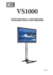
CDM-Toolbox
Digital Modulation in a simple way
Application Note
Products:
|
R&SSMW200A
|
R&SSMJ100A
|
R&SSMBV100A
|
R&SSMATE200A
|
R&SSMU200A
C. Neuhaeusler
08.2015-1GP96_6E
Application Note
This application note provides a brief
introduction into the capabilities of the
R&S Vector Signal Generators (VSG) to
create user defined digitally modulated
signals called Custom Digital Modulation
(CDM). Additionally an in depth
description of the functions and the
operation of the CDM-Toolbox is provided.
The CDM-Toolbox is application software
which allows an easy remote configuration
of CDM signals on R&S VSGs but also the
creation of data list and control list files
which are most useful to further extend the
application area of CDM signals.
Table of Contents
Table of Contents
1GP96_6E
1
Introduction ............................................................................ 5
1.1
Custom Digital Modulation (CDM) ..............................................................5
1.1.1
Data List ........................................................................................................7
1.1.2
Control List ...................................................................................................7
1.1.2.1
Control Signal Definition .............................................................................9
1.1.2.2
Marker Signal Definition ............................................................................10
1.2
Custom Digital Modulation (CDM) – Toolbox ..........................................11
2
Getting Started ..................................................................... 12
2.1
Feature Overview .......................................................................................12
2.2
System Requirements ................................................................................14
2.3
Installation Procedure ................................................................................15
2.4
First Steps ...................................................................................................16
2.4.1
CDM-Toolbox Start .....................................................................................16
2.4.1.1
Command Line Parameter .........................................................................16
2.4.2
CDM-Toolbox Operation ............................................................................17
2.4.3
CDM-Toolbox Settings Files ......................................................................17
3
Main Window ........................................................................ 18
3.1
Menu Bar .....................................................................................................19
3.2
Instrument Assignment .............................................................................20
3.3
Options Tab.................................................................................................21
3.4
Path A Tab ...................................................................................................22
3.4.1
RF .................................................................................................................23
3.4.2
Baseband/CDM ...........................................................................................23
3.5
Path B Tab ...................................................................................................25
3.6
Instrument Communication Log ...............................................................25
4
List Management Dialog ...................................................... 26
4.1
Data List Management ...............................................................................26
4.1.1
Data Input ....................................................................................................27
4.1.1.1
Modulation Type .........................................................................................27
4.1.1.2
Data Sources...............................................................................................28
4.1.2
Data List ......................................................................................................31
Rohde & Schwarz
CDM-Toolbox
2
Table of Contents
1GP96_6E
4.2
Control List Management ..........................................................................34
4.2.1
Data Input ....................................................................................................35
4.2.1.1
List Length ..................................................................................................35
4.2.1.2
Data Sources...............................................................................................36
4.2.2
Control List .................................................................................................37
5
Auxiliary Dialogs .................................................................. 39
5.1
Instrument Management Dialog ................................................................39
5.1.1
Instrument Announcement ........................................................................40
5.1.2
Instrument Pool ..........................................................................................41
5.2
Color Settings Dialog .................................................................................42
5.3
Trace Logs Dialog ......................................................................................43
6
Abbreviations ....................................................................... 45
7
References ............................................................................ 45
8
Appendix ............................................................................... 46
8.1
Release Notes .............................................................................................46
8.1.1
Version 1.4.0 (Initial release) .....................................................................46
8.1.2
Version 1.5.0 ...............................................................................................46
8.1.3
Version 1.5.1 ...............................................................................................46
8.1.4
Version 1.6.0 ...............................................................................................47
8.1.5
Version 1.6.1 ...............................................................................................47
8.1.6
Version 1.7.0 ...............................................................................................47
8.1.7
Version 1.7.5702.3657 ................................................................................47
9
Ordering Information ........................................................... 48
Rohde & Schwarz
CDM-Toolbox
3
Custom Digital Modulation (CDM)
The following abbreviations are used in this application note for Rohde & Schwarz
products:
®
The R&S SMW200A vector signal generator is referred to as SMW
®
The R&S SMBV100A vector signal generator is referred to as SMBV
®
The R&S SMU200A vector signal generator is referred to as SMU
®
The R&S SMATE200A vector signal generator is referred to as SMATE
®
The R&S SMJ100A vector signal generator is referred to as SMJ
NI-VISA is registered trademarks of National Instruments in the United States and/or
other countries.
1GP96_6E
Rohde & Schwarz
CDM-Toolbox
4
Introduction
Custom Digital Modulation (CDM)
1 Introduction
This application note provides a brief introduction into the capabilities of the R&S
Vector Signal Generators (VSG) to create user defined digitally modulated signals
called Custom Digital Modulation (CDM). Additionally an in depth description of the
functions and the operation of the CDM-Toolbox is provided.
The CDM-Toolbox is application software which allows an easy remote configuration of
CDM signals on R&S VSGs but also the creation of data list and control list files which
are most useful to further extend the application area of CDM signals.
1.1 Custom Digital Modulation (CDM)
All R&S Vector Signal Generators (VSGs) equipped with a realtime baseband
generator (see [1], [2], [3], [4] and [5] for details) are able to generate digitally
modulated baseband signals in realtime. The characteristic of these signals is either
determined by a certain standard (e.g. communication standards) or is completely user
definable. The later signal type is called Custom Digital Modulation (CDM).
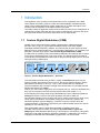
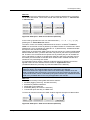
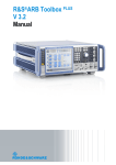
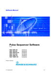
In CDM mode of operation nearly all baseband parameters and settings with an impact
on the signal characteristics are under user control. The following figure provides an
overview about the baseband functional blocks and processing steps to be run through
when generating a CDM signal:
Custom Digital Modulation
Data
Sources
Coding
Modulation
Filter
Smoothing
Filter
D
Q
...1000..
Bits
Bits
I
Sym.
A
Figure 1: Custom Digital Modulation – Overview
The VSG CDM functional block provides a variety of Data Sources which may be
used to internally generate bit sequences to be fed into the digital modulator. Simple
data patterns like binary 0 (‘All 0’) or 1 (‘All 1’) are available but also variable bit
sequences/patterns with a maximum length of 64 bits and also ITU compliant Pseudo
Random Bit Sequences (PRBS).
Further on if users want to apply their own bit sequences (e.g. channel coded data bits)
they may be provided to the VSG as binary data list files (see chapter 1.1.1).
In the following processing stage the provided data bits may be coded using different
Coding techniques to improve the signal properties and thus to ease the
decoding/demodulation on the receiver side. Since coding is required only when using
certain types of modulation the available coding types are directly related to the
selected modulation type (IQ-Mapping). Therefore to get an overview about the
coding/modulation combinations supported by the used R&S VSG refer to the specific
operating or user manual [1]..[5].
After applied data coding (if applicable) the digital modulation takes place.
The R&S VSGs support a variety of predefined digital Modulation Types (IQMapping) like ASK (amplitude shift keying), FSK (frequency shift keying), PSK (phase
shift keying) and QAM (quadrature amplitude modulation). Additionally user defined
mappings, created with the R&S MapWiz [7] application, can be imported.
1GP96_6E
Rohde & Schwarz
CDM-Toolbox
5
Introduction
Custom Digital Modulation (CDM)
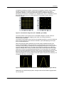
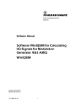
The digital modulation procedure is described by mapping of a data symbol (certain
number of data bits) to a certain complex IQ-constellation point in a so called
constellation diagram. To get a first impression about constellation diagrams the
7
following figures show the constellation of a 128QAM with 128 (2 ) constellation points
3
and 7 bits per symbol and of an 8PSK with 8 (2 ) constellation points and thus
3 bits per symbol:
Figure 2: Constellation Diagrams (left: 128QAM, right: 8PSK)
The exact position of the symbols in the constellation diagram (I and Q values) is
determined by the applicable mapping rules which are mostly specified by
communication standards.
The maximum achievable symbol rate of the modulator depends on the used VSG and
it also strongly depends on the selected modulation types (IQ-Mapping) and ranges
from 15 to 50 MSymbols/s.
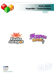
After the performed digital modulation the symbol stream (baseband signal) runs
through a digital Filter to shape the signal in a well-defined way prior to the RF upconversion. This is done to optimize the overall signal performance in the time domain
(e.g. Inter Symbol Interference, ISI) and/or in the frequency domain (e.g. Adjacent
Channel Leakage Ratio, ACLR). To fulfill a wide range of filter requirements, the R&S
VSGs offer a variety of predefined baseband filters. All of these filters are originated
from communication standards but most of them can be parameterized by one or more
filter type specific parameters to align their characteristics with application specific
needs. Exemplarily the following figures show the impulse response (time domain) of a
rectangular filter and of a Gauss filter:
Figure 3: Impuls Response of Baseband Filters (left: Rectangular, right: Gauss)
Additionally user defined shaping filters, designed with the R&S FiltWiz [8] application,
can be imported.
1GP96_6E
Rohde & Schwarz
CDM-Toolbox
6
Introduction
Custom Digital Modulation (CDM)
1.1.1 Data List
A data list may be used to provide data bits to the VSG CDM functional block if none of
the available VSG internal data source (e.g. PRBS, pattern…) is applicable since user
specific data sequences are required (e.g. channel coded data bits).
The name of a data list file is user defined; the file extension has to be .dm_iqd.
In general the maximum length of a data list (number of contained bits) is determined
by the size of the data list memory of the used R&S VSG (see related data sheet). The
data list size which may be processed by the CDM-Toolbox is limited to 250 Mbit.
Most R&S VSGs provide integrated functions to load existing (on the VSG memory)
data lists, to create new data lists and also to edit existing ones. For a more convenient
processing of data lists, especially in case of lists containing a huge amount of data the
usage of the CDM-Toolbox is recommended.
In general a data list file consists of two main sections. The first section the so called
header contains several mandatory and optional ASCII data list tags which are used to
provide information about the data list file content but also to control the VSG. The
second section holds the data bits in a binary format.
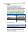
The following table summarizes all specified R&S data list tags and their meaning:
Data List – Header Tags
Tag Name
Mandatory
Meaning
{TYPE:SMU-DL,0}
Yes
{COMMENT:MyComment}
No
{COPYRIGHT:MyCopyright}
{DATE:2013-06-03;21:51:00}
{DATA BITLENGTH:444}
{DATA LIST-57:#bbbbb…}
No
No
Yes
Yes
Set the file format to data list. The format ‘SMUDL’ is applicable for all R&S VSGs.
The checksum is always zero for data lists.
This tag must be the first one in the data list file.
For example comments regarding the data list
content and/or usage.
Copyright notes
Creation date of the data list
Number of valid data bits within the data list
The binary data list: 8bit, MSB first.
The length value is in full bytes and comprises
the data bytes and the byte required for the #mark. This tag must be the last one in the data
list file.
Table 1: Data List – Header Tags
Example: The tags shown in the table above are applicable for an R&S data list file
which contains 444 binary data bits. This amount of data bits to be hold by the data
list results in 444/8 = 55.5 bytes of memory. Since the elementary unit for data
storage is one byte the nearest integer number greater than 55.5 (56) is required to
store the total amount of data bits. Including the memory of one byte needed for the
leading # mark a data list length of 57 bytes is required.
Note: The last 4 data bits (0.5 byte) within the last data byte are ignored by the VSG.
1.1.2 Control List
Control lists may be used to modify the shape of the encoded and modulated CDM
signal. Areas of lower RF signal level, Continuous Wave (CW) sections without
modulation as well as bursts can be defined.
Additionally up to four marker signals can be activated or deactivated at any symbol
position which may thus serve as trigger signals for external instruments or for the
synchronization of multiple VSG baseband units.
1GP96_6E
Rohde & Schwarz
CDM-Toolbox
7
Introduction
Custom Digital Modulation (CDM)
The name of a control list file is user defined; the file extension has to be .dm_iqc.
Any VSG provides integrated functions to load existing (on the VSG memory) control
lists, to create new control lists, to edit existing ones and to graphically show the
contained marker and control signals.
For a more convenient processing of control lists the usage of the CDM-Toolbox is
recommended.
In contrast to data list files a control list file consists of only one section with mandatory
and optional ASCII control list tags. These tags are used to provide information about
the control list file content and are essential to specify the marker and control signals.
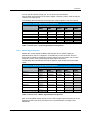
The following table summarizes all specified R&S control list tags and their meaning:
Control List – Tags
Tag Name
Mandatory
Meaning
{TYPE:SMU-CL,0}
Yes
{COMMENT:MyComment}
No
{COPYRIGHT:MyCopyright}
{DATE:2013-06-03;21:54:01}
{CONTROL LENGTH:100}
No
No
Yes
Set the file format to control list. The format
‘SMU-CL’ is applicable for all R&S VSGs.
The checksum is always zero for control lists.
This tag must be the first one in the control list
file.
For example comments regarding the control list
content and/or usage.
Copyright notes
Creation date of the control list
Specifies the length (symbols) and thus the
periodicity of the entire control list.
Marker Signals:
{MARKER LIST 1:1:1;20:0}
No
{MARKER LIST 2:0:0}
{MARKER LIST 3:0:0}
{MARKER LIST 4:0:0}
Control Signals:
{BURST LIST:40:1;80:0}
No
No
No
{LEVATT LIST 1:50:1;80:0}
No
{CW MODE LIST:60:1;80:0}
No
{HOP LIST:0:0}
No
No
Defines the slopes of marker signal 1
(Symbol number:State) and thus areas with
active/inactive marker signal.
Defines the slopes of marker signal 2
Defines the slopes of marker signal 3
Defines the slopes of marker signal 4
Defines the slopes for bursted signals
(Symbol number:State) and thus areas with
active/deactive RF signal.
Note: Power ramping has to be activated
Defines the slopes for level attenuation
(Symbol number:State) and thus areas with
enabled/disabled level attenuation.
Note: Power ramping has to be activated
Defines the slopes for deactivated modulation
(Symbol number:State) and thus areas with
activated/deactivated modulation.
Defines the slopes for e.g. frequency hopping
(Symbol number:State).
Table 2: Control List – Tags
Example: The tags shown in the table above are applicable for an R&S control list
file with a control length/periodicity of 100 symbols. MARKER signal 1 is set to high at
symbol 1 and reset to 0 at symbol 20. The MARKER signals 2-4 remain unused.
The BURST tag specifies that the RF signal has to be activated at symbol 40 and
deactivated at symbol 80. According to the LEVATT tag an additional attenuation has
to be applied on the RF burst level starting from symbol 50 till symbol 79. The CW
MODE tag forces the deactivation of the modulation between symbol 60 and 79.
Frequency hopping is not needed and therefore the HOP signal which may be used
to trigger an RF-List step remains unused.
1GP96_6E
Rohde & Schwarz
CDM-Toolbox
8
Introduction
Custom Digital Modulation (CDM)
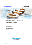
1.1.2.1
Control Signal Definition
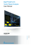
Most R&S VSGs support several control signals per baseband which are customizable
via the control list. All of these signals are primarily used VSG internally to modify the
shape of the RF signal.
The following figure gives an impression how these signals influence the RF signal
after the control list activation:
1 BURST
0
1 CWMODE
0
1 LEVATT
0
RF Lev1
S0 S1
0 1 2 3
8
14
16
18
21
24
Symbol
BURST
Ramp Time
RF Lev1
Ramp Func
Rise Dly
Fall Dly
Ramp Time
1) ‘Power ramping’ has to be enabled and an ‘Attenuation’ value > 0 has to be set.
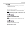
Figure 4: Control List – RF Signal Shaping
After activation of ‘Power Ramping’ only in areas with the BURST signal set to 1 a RF
output signal with the specified RF level is generated. Burst areas with a LEVATT
signal set to 1 undergo certain additional attenuation and in all areas with CW MODE
set to 1 the modulation data is skipped which results in an unmodulated CW RF signal
during this period.
Note: The user has to take care to provide dummy data bits during a CW MODE area
since the data stream is not interrupted during this period of time but the data bits are
discarded.
In case of burst definitions there are additional signal parameters that control the burst
attenuation in certain areas but also the burst ramping shape, such as ramp function,
rise and fall times as well as delays. These parameters are not directly set in the
control list but by dedicated parameters provided by the VSG CDM power ramping
functions or by the CDM-Toolbox (see chapter 3.4.2).
Besides the VSG internal usage of these control signals all of them are also available
1GP96_6E
Rohde & Schwarz
CDM-Toolbox
9
Introduction
Custom Digital Modulation (CDM)
for user specific external usage (e.g. for any kind of synchronization).
Also the HOP signal which may be used to trigger a frequency step in a RF list may be
routed to VSG output ports.
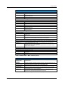
The following table summarizes the assignment of these signals to the VSG outputs:
Control List – Control Signal/Output Assignment
Control Signal
Vector Signal Generator Output Port
SMW
BURST A
CW MODE A
SMU
T/M/(C)1..31
T/M/(C)1..31
AuxIO-Pin45
AuxIO-Pin27
USER1..41
1
LEVATT A
T/M/(C)1..3
AuxIO-Pin26
HOP A
T/M/(C)1..31
USER1..41
1
BURST B
T/M/(C)4..6
USER1..41
1
CW MODE B
T/M/(C)4..6
USER1..41
1
LEVATT B
T/M/(C)4..6
USER1..41
HOP B
T/M/(C)4..61
USER1..41
1) Selection not supported by the CDM-Toolbox
SMATE
SMJ
SMBV
AuxIO-Pin45
AuxIO-Pin27
USER1..41
AuxIO-Pin26
USER1..41
USER1..41
USER1..41
USER1..41
USER1..41
AuxIO-Pin45
AuxIO-Pin27
USER1..41
AuxIO-Pin26
USER1..41
-
-
Table 3: Control List – Control Signal/Output Assignment
1.1.2.2
Marker Signal Definition
Besides the control signals the R&S VSGs support up to 4 marker signals per
baseband which may be configured in a versatile way via the control list. Some of
these marker signals are assigned to specific output connectors others can be freely
assigned to some of the general purpose input/output connectors.
The following table summarizes the marker signal to output assignment for the R&S
VSGs:
Control List – Marker Signal/Output Assignment
Marker Signal
Vector Signal Generator Output Port
SMW
Marker 1A
SMU
USER1..6
MARKER1
T/M1..31
Marker 2A
USER1..6
MARKER2
T/M1..31
Marker 3A
USER1..6
AuxIO-Pin41
T/M1..31
Marker 4A
USER1..4
Marker 1B
USER1..6
MARKER1B
T/M4..61
Marker 2B
USER1..6
AuxIO-Pin42
T/M4..61
Marker 3B
USER1..6
AuxIO-Pin43
T/M4..61
Marker 4B
USER1..4
1) Selection not supported by the CDM-Toolbox
SMATE
SMJ
SMBV
MARKER1
MARKER1
MARKER1
MARKER2
MARKER2
MARKER2
AuxIO-Pin41
AuxIO-Pin41
-
USER1..4
MARKER1B
USER1..4
-
-
AuxIO-Pin42
-
-
AuxIO-Pin43
-
-
USER1..4
-
-
Table 4: Control List – Marker Signal/Output Assignment
Each of the available marker signals can be used to trigger external instruments or the
Equipment Under Test (EUT) as well as for the synchronization of multiple VSG
basebands.
1GP96_6E
Rohde & Schwarz
CDM-Toolbox
10
Introduction
Custom Digital Modulation (CDM) – Toolbox
1.2 Custom Digital Modulation (CDM) – Toolbox
In general the CDM-Toolbox is intended to ease the operation of the powerful CDM
functionality offered by the R&S VSGs.
It thus supports the definition and setup of application specific digitally modulated
signals which includes the specification of the modulation data source, coding type,
modulation type, symbol rate and baseband filter type.
Besides these elementary baseband functions the creation, activation and
administration of data and control lists is covered, too. Further advantages are the
included marker control functionality and the integrated means to remotely control
basic RF parameters like frequency and level.
An in depth description of the CDM-Toolbox is provided by the following chapters.
1GP96_6E
Rohde & Schwarz
CDM-Toolbox
11
Getting Started
Feature Overview
2 Getting Started
This chapter provides in depth information about the available CDM-Toolbox features,
summarizes the PC system requirements which have to be fulfilled to successfully
install and run the CDM-Toolbox, guides through the installation process and gives an
first impression how to operate the CDM-Toolbox.
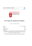
2.1 Feature Overview
The CDM-Toolbox is a powerful and easy-to-use software tool with the following
features:
R&S Vector Signal Generator
Custom Digital Modulation - B
Custom Digital Modulation - A
User
Mapping
*.vam
User
Filter
*.vaf
RF - B
RF - A
Data
Sources
Coding
Modulation
Filter
Smoothing
Filter
D
RF
Settings
Q
Bits
...1000..
Bits
I
Sym.
A
Markers
Data List
....
0100
1111
...
Control List
MARKER
LEVATT
CW MODE
BURST
HOP
Marker Signals
CDM-Toolbox
Data List
Manager
Control List
Manager
1
Instrument
Manager
2
3
CDM
Control
RF
Control
4
5
Figure 5: CDM-Toolbox – Overview
Main Features
Data List Manager
Data lists up to a length of 250 Mbit can be:
created
From the scratch by using bit patterns, predefined bit sequences, PRBS (9, 11, 15,
16, 20, 21, 23) and ASCII data files.
imported
From already existing data list files.
concatenated
Either imported data list files or the internal data source of the CDM-Toolbox may
be used.
modified
Any bit of a data list can be toggled.
displayed
The data list bits can be displayed as symbols (binary) or as bytes
(binary/hexadecimal).
Table 5: CDM-Toolbox – Main Features (Part 1)
1GP96_6E
Rohde & Schwarz
CDM-Toolbox
12
Getting Started
Feature Overview
Main Features
Data List Manager
exported
transferred
activated
Any data list can be exported/saved as ASCII data file or as a binary data list file.
Data lists which have been exported as data list files can be transferred to any
assigned R&S VSG.
Any data list file which was transferred to an R&S VSG can be selected/activated.
Control Lists Manager
Control lists can be:
created
imported
modified
exported
transferred
activated
From the scratch.
From already existing control list files.
Any control list tag can be modified based on the user’s needs.
Any control list can be exported/saved as control list file.
Control lists which have been exported as control list files can be transferred to any
assigned R&S VSG.
Any control list file which was transferred to an R&S VSG can be
selected/activated.
Instrument Manager
R&S VSGs can be:
connected
searched
assigned
VSGs can be connected with the PC system running the CDM-Toolbox via GPIB,
USB or LAN.
The supported remote control interfaces can be scanned for connected VSGs.
Any VSG either manually specified or detected during an interface scan can be
assigned to the CDM-Toolbox to allow remote control operation.
Custom Digital Modulation (CDM) Control
Ease the operation of the powerful CDM functionality of the R&S VSGs on up to two baseband paths in
parallel. The CDM section(s) of any assigned VSG can be:
configured
The modulation data source, coding type, modulation type, symbol rate and
baseband filter type can be configured.
Further on the power ramping of bursted signals and also the available marker
signal can be configured.
activated
The VSG CDM section can be activated/deactivated.
RF Control
The RF section of any assigned VSG can be:
configured
The basic parameters of the RF section, the level and the frequency can be
configured.
activated
The RF signal can be activated/deactivated.
Table 6: CDM-Toolbox – Main Features (Part 2)
Auxiliary Features and Usability
Simple and
intuitive user
interface
Tool tips
Communication
Log Window
Trace Log Dialog
Option List
Every feature and user interface parameter has been designed to be intuitively and
easily learned.
Each user interface parameter provides information about the required user input
and if applicable also information about the parameter range.
Shows the remote communication with the connected VSG.
Shows the operation steps and status of the CDM-Toolbox and informs about
critical situations (e.g. VSG not accessible).
The information about installed HW/SW options can be requested from the
assigned VSG, displayed and exported as an ASCII list.
Table 7: CDM-Toolbox – Auxiliary Features and Usability
1GP96_6E
Rohde & Schwarz
CDM-Toolbox
13
Getting Started
System Requirements
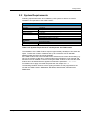
2.2 System Requirements
Following requirements have to be fulfilled by a PC system to allow a successful
installation and operation of the CDM-Toolbox:
System Requirements
1
Hardware
Hard disc
RAM
Processor clock
Screen resolution
Remote control IF
>30 MByte
>1 GByte
>2 GHz (to allow fast data list processing)
>1280x800
LAN 100Mbit or 1Gbit
USB 2.0 (optionally)
GPIB/IEEE488 Interface (optionally)
Software
OS
Microsoft Windows 7
VISA Library
NI VISA V5.1.1
1) Functionality was tested by R&S with following hardware and software components
Table 8: PC System Requirements to install/operate the CDM-Toolbox
The installation of the CDM-Toolbox requires approximately 20 MByte of free hard disc
space. To allow the creation of data list files up to a maximum size of 250 MBit
additional hard disc space should be available.
If the CDM-Toolbox has to be used without the offered remote control functionality (e.g.
only for the creation of data list or control list files) the VISA library is not required and
has thus not to be installed on the PC running the CDM-Toolbox. In this case the CDM
toolbox has to be started with the applied command line parameter ‘--no-visa’.
For details how to apply command line parameter see chapter 2.4.1.1.
The following Rohde & Schwarz vector signal generators are fully supported for the
use with the CDM-Toolbox: SMW200A, SMU200A, SMATE200A, SMJ100A and
SMBV100A.
1GP96_6E
Rohde & Schwarz
CDM-Toolbox
14
Getting Started
Installation Procedure
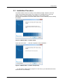
2.3 Installation Procedure
The CDM-Toolbox comes as a ready to use installer package. However, there are
certain prerequisites/requirements (see chapter 2.2 for details) which have to be
fulfilled to allow a proper installation and operation of the CDM-Toolbox.
Once these requirements are met the CDM-Toolbox can be installed by simply starting
the installer.
Figure 6: CDM-Toolbox – Installer (Start)
Follow the instructions ……and after completion of the installation….
Figure 7: CDM-Toolbox – Installer (Completion)
….you will find the CDM-Toolbox program as a new entry in your Windows start menu
and as an icon on the desktop.
1GP96_6E
Rohde & Schwarz
CDM-Toolbox
15
Getting Started
First Steps
2.4 First Steps
This paragraph provides some basic information to become familiar with the
configuration and operation of the CDM-Toolbox.
2.4.1 CDM-Toolbox Start
The CDM-Toolbox is normally started via the related desktop icon or the start menu
entry without any additional preparation steps.
However if the CDM-Toolbox has to be used without the offered remote control
functionality (e.g. only for the creation of data list or control list files) and thus the VISA
library was not installed the CDM toolbox has to be started with the applied command
line parameter ‘--no-visa’. This will prevent the attempt of the CDM-Toolbox to load
the VISA library.
To show extended logging information within the ‘Trace Logs’ dialog (see chapter 5.3
for details), the CDM-Toolbox has to be started with the command line parameters
‘--debug' or ‘--filedebug'.
Note: The latter parameters should only be used for debugging purposes (e.g. to
provide additional information to the R&S customer support in case of malfunctions)
since it slows down the application significantly.
2.4.1.1
Command Line Parameter
To apply the required command line parameter(s) the related ‘Properties’ dialog of the
CDM-Toolbox has to be opened first. This is done by a right mouse click on the
desktop icon (or the start menu entry) of the CDM-Toolbox followed by the selection of
the ‘Properties’ item in the appearing context menu.
In a final step the command line parameter(s) have to be appended to the ‘Target’
parameter (CDM-Toolbox executable) provided by the ‘Shortcut’ tab of the ‘Properties’
dialog.
Figure 8: CDM-Toolbox – Start with Command Line Parameter (--debug)
1GP96_6E
Rohde & Schwarz
CDM-Toolbox
16
Getting Started
First Steps
2.4.2 CDM-Toolbox Operation
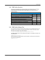
To speed up the familiarization with the operation of the CDM-Toolbox the following
table provides references to the functional descriptions of commonly used
functions/features of the CDM-Toolbox. Bold characters are used for functions of
capital importance:
CDM-Toolbox Operation
Operation
Chapter
Page
Create, save (export) and transfer a data list file
Create, save (export) and transfer a control list file
Search for available VSGs on a certain remote control interface
Announce a certain VSG to the CDM-Toolbox instrument pool manually
Get information about VSGs announced to the CDM-Toolbox
Remove a VSG from the CDM-Toolbox instrument pool
Assign a certain VSG to the CDM-Toolbox (to allow remote control)
Get information about the installed options on a assigned VSG
Perform CDM and RF configurations on an assigned VSG
Modify the CDM-Toolbox style and colors
Show trace log information
4.1
4.2
5.1.1
26
34
40
5.1.2
41
3.2
3.3
3.4
5.2
5.3
20
21
22
42
43
Table 9: CDM-Toolbox – Operation
2.4.3 CDM-Toolbox Settings Files
For convenience reasons the CDM-Toolbox makes use of two settings files which are
intended to recover certain user specific settings after a restart of the CDM-Toolbox.
Both of them are stored in the ‘Users’ directory:
C:\Users\<UserName>\AppData\Roaming\Rohde-Schwarz\
The CDM-Toolbox style and color settings (see chapter 5.2 for details) are saved in the
color settings file:
CDMToolbox-colors.ini
All other settings (e.g. dialog positions, path information, instrument pool information...)
are saved in the settings file:
CDMToolbox.ini
1GP96_6E
Rohde & Schwarz
CDM-Toolbox
17
Main Window
First Steps
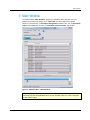
3 Main Window
The CDM-Toolbox ‘Main Window’ shows up immediately after program start. It is
broken up into four main areas, the ‘Menu Bar’ and three instrument related
sections. Those are the ‘Instrument Assignment’ selection box, the Instrument
‘Option’ and ‘Path’ tabs and the ‘Instrument Communication’ log window.
1
2
3
4
Figure 9: CDM-Toolbox – Main Window
Note: Immediately after the first startup of the CDM-Toolbox all instrument related
GUI elements are empty/disabled since in this operation phase no VSG is assigned
to the CDM-Toolbox.
1GP96_6E
Rohde & Schwarz
CDM-Toolbox
18
Main Window
Menu Bar
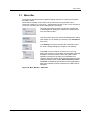
3.1 Menu Bar
The menu bar provides access to different dialogs required to configure and operate
the CDM-Toolbox.
Commands accessible via the menu bar are referenced using the Menu Item →
Command notation (e.g. Instrument → Management means to click on the ‘Instrument’
menu item, and then click on the ‘Management’ command).
The ‘List’ menu item provides commands to activate the
‘List Management’ dialog (see chapter 4 for details) and to
‘Exit’ the CDM-Toolbox.
The command to open the ‘Instrument Management’ dialog
(see chapter 5.1 for details) is provided by the ‘Instrument’
menu item.
The ‘Settings’ menu item provides the command to open
the ‘Color’ settings dialog (see chapter 5.2 for details).
The ‘Help’ menu item allows access to the ‘Trace Log’
dialog (see chapter 5.3 for details) via the related command
and also to some information ‘About’ the CDM-Toolbox
software including the copyright, an email address for
customer support and also some legal and software license
related information (see chapter Error! Reference source
not found. for details about software licenses applicable to
third party software products included in the CDM-Toolbox
software).
Figure 10: Main Window – Menu Bar
1GP96_6E
Rohde & Schwarz
CDM-Toolbox
19
Main Window
Instrument Assignment
3.2 Instrument Assignment
The ‘Instrument Assignment’ selection box provides a list of VSGs which are
currently announced to the ‘Instrument Pool’ (see chapter 5.1.2) and are thus available
for an assignment to the CDM-Toolbox to allow remote control operations.
To get an overview about the available VSGs the selection box has to be opened by a
left mouse click first.
2
1
To facilitate an easy selection of the desired VSG,
identification parameters (type, serial number and remote
control interface) of all VSGs are available. Furthermore
the ‘Instrument Assignment’ status indicator provides
information about the assignment status at a glance.
Figure 11: Main Window – Instrument Assignment
Instrument Assignment – Status Indicator
Indicator
Meaning
No (enabled) VSG available in the instrument pool for assignment.
At least one (enabled) VSG available for assignment
The top most VSG within the selection box is already assigned.
Table 10: Instrument Assignment – Status Indicator
To initiate the assignment process of a certain VSG offered by the selection box the
desired VSG has to be selected by a left mouse click.
During the assignment phase the CDM-Toolbox establishes the remote control
connection to the chosen VSG and performs a VSG preset afterwards. Additionally
several parameters regarding the instrument assembly (e.g. installed options) are
retrieved to allow a proper configuration of the instrument tabs of the CDM-Toolbox
‘Main Window’.
After a successful finalization of the VSG assignment the color of the status indicator
changes to green and the instrument tabs are enabled to allow further remote control
interaction with the assigned VSG.
Note: An established assignment can be released by either deleting/disabling of the
VSG in the instrument pool or by assigning another VSG to the CDM-Toolbox.
The CDM-Toolbox takes care that the VSG baseband and RF functional unit(s) will
be deactivated during the release process.
1GP96_6E
Rohde & Schwarz
CDM-Toolbox
20
Main Window
Options Tab
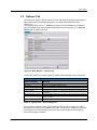
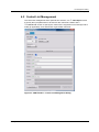
3.3 Options Tab
The instrument ‘Options’ tab as well as the ‘Path A/B’ tabs are related to the assigned
R&S VSG and are thus enabled only after a successful VSG assignment (see
chapter 3.2).
The ‘Options’ tab shows an ‘Options’ list which covers all hardware and software
options installed on the assigned R&S VSG and also the functionality to ’Save the
Option List’ as a plain ASCII file.
1
2
Figure 12: Main Window – Options Tab
To ease the location of a certain option the CDM-Toolbox specifies option categories:
Options Tab – Option Categories
Option Category
Meaning
RF Path(s)
BB Path(s)
MIMO/Fading
Noise
GNSS (internal)
RF path related options
Baseband unit related hardware options
MIMO/Fading simulator related options
AWGN related options
GNSS (GPS, GLONASS…) related options, based on VSG internal signal
calculation
Digital standards related options, based on VSG internal signal calculation
Digital standards related options, based on external (e.g. WinIQSIM2)
signal calculation
Options which do not belong to any option category above
Digital Standards (internal)
Digital Standards (external)
Miscellaneous
Table 11: Options Tab – Option Categories
To increase the clarity a certain option category shows up only if at least one option
belonging to this category is installed on the VSG. The options in detail (type, path and
functionality) can be shown/hide by a mouse click on the triangle on the left side of
each option category headline.
1GP96_6E
Rohde & Schwarz
CDM-Toolbox
21
Main Window
Path A Tab
3.4 Path A Tab
The instrument ‘Path A’ tab as well as the ‘Path B’ and ‘Options’ tab are related to the
assigned R&S VSG and are thus enabled only after a successful VSG assignment
(see chapter 3.2).
The ‘Path A’ tab comprises the functionality to perform all VSG settings to generate a
custom digitally modulated RF signal on path A.
The tab consists of two areas the ‘RF’ section which is used to perform all basic RF
settings and the ‘Baseband/CDM’ section to configure the custom digital
modulation baseband parameters.
1
2
Figure 13: Main Window – Path A Tab
Note: To prevent any VSG configuration error all selection- and entry boxes are
initialized based on the capabilities of the assigned VSG.
Additionally all entry boxes provide VSG specific information (tooltips) about the
supported parameter range and perform a range check of all provided parameters.
Parameters which exceed the specified range are ignored and are thus not sent to
the assigned VSG.
1GP96_6E
Rohde & Schwarz
CDM-Toolbox
22
Main Window
Path A Tab
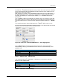
3.4.1 RF
The ‘RF’ section is intended to specify the required ‘RF Frequency’ and the (RMS)
‘RF level’ but also to switch the RF signal ‘ON’ or ‘OFF’.
3
1
2
4
Figure 14: Path A Tab – RF Section
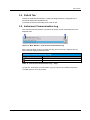
3.4.2 Baseband/CDM
The ‘Baseband/CDM’ section is used to configure the Custom Digital Modulation
parameters offered by the assigned VSG. Since some of these parameters depend on
each other (range and availability) the appearance of this section is not static but
variable.
1
2
3
6
4
5
Figure 15: Path A Tab – Baseband/CDM Section
For details and background about this parameters refer to the VSG specific user- or
operating manual [1]..[5].
The ‘Data List’ selection box provides a list of all data lists available on the
assigned VSG within the dedicated data list directory (see chapter 4.1.2 for details
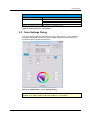
about data list creation).
1GP96_6E
Rohde & Schwarz
CDM-Toolbox
23
Main Window
Path A Tab
In parallel the ‘Control List’ selection box provides a list of all control lists available
on the assigned VSG within the dedicated control list directory (see chapter 4.2.2 for
details about control list creation).
After selection of a certain control list additional parameters show up at the bottom of
the ‘Baseband/CDM’ section to allow the configuration of signal properties which are
not solely specified by the control list (see chapter 1.1.2.1 for details about these
parameters):
The ‘Ramp’ tab places all parameters at disposal which are required to control the
burst shape, which is of interest if the burst tag is used within the selected control list.
The VSG output ports to be used for marker signals are defined within the ‘Marker’
tab.
To activate/deactivate a defined CDM signal the ‘ON’/ ‘OFF’ button is used.
In case of a user defined modulation (mapping) and/or a user defined filter type related
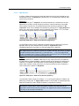
selection boxes are available to select the desired file.
1
2
Figure 16: Path A Tab – Baseband/CDM Section – User Mapping/Filter
The ‘Mapping File’ selection box provides a list of user specific modulation
mapping files (*.vam) [7]. These files have to be saved in a specific directory of the
assigned VSG.
Mapping Files – VSG Directory
VSG Type
Data List Directory
SMW, SMBV
SMU, SMATE, SMJ
/var/user/Mappings
D:\Mappings
Table 12: Mapping Files – VSG Directory
User designed shaping ‘Filter Files’ (*.vaf) [8] have to be saved in a specific
directory of the assigned VSG.
Filter Files – VSG Directory
VSG Type
Data List Directory
SMW, SMBV
SMU, SMATE, SMJ
/var/user/Filters
D:\Filters
Table 13: Filter Files – VSG Directory
1GP96_6E
Rohde & Schwarz
CDM-Toolbox
24
Main Window
Path B Tab
3.5 Path B Tab
This tab is enabled automatically if a VSG was assigned which is equipped with a
second RF-path and/or baseband unit.
It provides the same functionality as the ‘Path A’ tab.
3.6 Instrument Communication Log
The ‘Instrument Communication’ log shows all remote control commands sent to the
assigned VSG.
1
2
Figure 17: Main Window – Instrument Communication Log
Each communication log entry consists of a flag which is used to categorize the log
entries and the logging information itself.
Instrument Communication Log – Flags
Flag
Meaning
Any successful action
Error
Table 14: Instrument Communication Log – Flags
To clear the ‘Instrument Communication’ log (e.g. to get rid of outdated entries) the
‘Clear’ button has to be pressed.
1GP96_6E
Rohde & Schwarz
CDM-Toolbox
25
List Management Dialog
Data List Management
4 List Management Dialog
The ‘List Management’ dialog which is activated by the menu bar List → Management
command includes all functions to create, modify, save and transfer R&S data and
control lists. The tab based dialog offers two register tabs one to manage data lists and
a second one to deal with control lists.
The following paragraphs provide a detailed explanation of the available list
management functions and their usage. For additional detailed background information
about R&S data- and control lists see chapter 1.1.
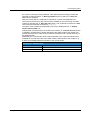
4.1 Data List Management
The data list management tab is split into two sections, one ‘Data Input’ section to
specify the input parameters to be used for the data list generation and a ‘Data List‘
section to visualize, modify (if applicable), save and transfer a generated data list.
1
2
Figure 18: CDM-Toolbox – Data List Management Dialog
1GP96_6E
Rohde & Schwarz
CDM-Toolbox
26
List Management Dialog
Data List Management
4.1.1 Data Input
The ‘Data Input’ section provides all functions to specify the data (content and amount)
to be put into or to append to a data list. First of all the ‘Modulation Type’ specific
settings have to be made further on the ‘Data Source’ has to be selected.
4.1.1.1
Modulation Type
With the ‘Modulation Type’ selection box the required digital modulation scheme is
selected. This setting does not directly affect the data list content but defines the
number of ‘Bit/Symbol’ and is thus essential for a proper determination of the list
length (bit count).
1
2
3
4
Figure 19: Data Input – Modulation Type Section
The amount of data to be put into a data list can be specified for some of the selectable
data sources (Sequence, Pattern and PRBS; see chapter 4.1.1.2 for details) by a
number of ‘Symbols’ or by a quantity of ‘Bits’. For a file based data sources
(Data file and Data list) the amount of data is determined by the number of data bits
contained in the selected file and may thus not be modified manually. Note that the
total data list length is limited to a maximum of 250 Mbit.
The decision about the desired data amount specification method (via Symbols or via
Bits) is made via the checkboxes associated to the Symbols/Bits boxes.
If the number of specified bits results in a none integer number of symbols a warning
symbols shows up above the symbols box to indicate that this would prevent a proper
determination of the vector constellation of the last symbol (some bits are missing).
Another warning shows up above the bits box if a PRBS sequence was selected (see
chapter 4.1.1.2) as data source and the specified number of data bits would result in a
none integer number of ‘used’ PRBS sequences which may for example result in
synchronization and/or bit error problems if the digitally modulated signal is used for
receiver test.
Example: In the figure shown above the bit count based data amount specification is
activated. The specified number of 512 bits results (based on the modulation type
specific 7 bits/symbol) in a none integer number of 73.1 symbols. This symbol/bit
mismatch is indicated by the warning sign shown above the symbols box.
The warning sign above the bits box shows up since a PRBS9 (sequence length:
511 bits) was selected which would result in a none integer number of PRBS
sequences.
1GP96_6E
Rohde & Schwarz
CDM-Toolbox
27
List Management Dialog
Data List Management
4.1.1.2
Data Sources
A variety of data sources used to provide the data bits to be put into the data list can
be selected via the ‘Data Source’ selection box. In the following the different data
sources are introduced:
Sequence:
The data source type ‘Sequence’ should be selected if it is sufficient for the test
application to provide a certain simple bit sequence. With the selection of this data
source type a selection box is activated that provides several pre-defined ‘Bit
sequences’ which can be added to the data list by pressing the ‘Apply Sequence’
button. If the previously specified number of data bits (see chapter 4.1.1.1) exceeds
the sequence length the sequence is repeated accordingly.
1
4
2
3
Figure 20: Data Input – Data Source Section (Sequence)
For applications which require a data list containing data from different sources the
append mode has to be activated via the related ‘Append ON‘ button
(Available/enabled only if already any data was added to the data list).
Example: In the above figure the data sequence ‘1100’ was selected. By pressing
the ‘Apply Sequence’ button this sequence is added to the data list until the specified
number of bits has been reached (e.g. 110011001100……110). The ‘Append ON’
button is disabled since currently no data is within the data list. The red indicator sign
informs the user about the deactivated append mode.
Pattern:
Users may select the ‘Pattern’ data source if only some bits have to be added to
the data list but a greater flexibility in defining the bits as provided by the data source
‘Sequence’ is required. This mode allows to freely defining data patterns of flexible
length. After selection of this data source an entry box shows up which enables the
user to specify the needed ‘Bit pattern’.
1
3
2
Figure 21: Data Input – Data Source Section (Pattern)
The specified number of bits (see chapter 4.1.1.1) of the given pattern is added to the
data list by pressing the ‘Apply Pattern’ button. If the number of required/specified
data bits exceeds the pattern length the pattern is repeated accordingly.
Example: In the above figure the data pattern ‘1011100111’ was selected. By
pressing the ‘Apply Pattern’ button the pattern is added to the data list until the
specified number of bits has been reached. The ‘Append ON’ button is disabled since
currently no data is within the data list.
1GP96_6E
Rohde & Schwarz
CDM-Toolbox
28
List Management Dialog
Data List Management
PRBS (Pseudo Random Bit Sequences):
After selection of the ‘PRBS’ data source the ‘PRBS Type’ selection box shows
up which allows the user to specify the PRBS type best fitting with the test application.
1
2
3
Figure 22: Data Input – Data Source Section (PRBS)
The ‘Apply PRBS’ button has to be used to add the specified number of bits (see
chapter 4.1.1.1) of the selected PRBS type to the data list.
Example: In the figure above the ‘PRBS9’ was selected which will be added to the
data list with the specified number of data bits after pressing the ‘Apply PRBS’ button.
The ‘Append ON’ button is disabled since currently no data is within the data list.
Following PRBS types of different length N may be selected as a data source for data
list generation:
Data Sources – Supported PRBS Types
Type N
Sequence Length
PRBS9
PRBS11
1
Standard
Feedback
2
Seed
Inverted
511 bits
2,047 bits
[11], 2.1
4, 0 All 1
No
[11], 2.2, [10],
2, 0 All 1
No
2.1
PRBS15
32,767 bits [9], 2.1
1, 0 All 1
Yes
PRBS16
65,535 bits 5, 3, 2, 0 All 1
No
PRBS20
1,058,575 bits [11], 2.3
3, 0 All 1
No
PRBS21
2,097,151 bits 2, 0 All 1
No
PRBS23
8,388,607 bits [9], 2.2
5, 0 All 1
Yes
1) In case of data lists exceeding the length of a selected PRBS sequence the sequence is repeated.
2) Feedback after these taps/registers.
Table 15: Data Sources – Supported PRBS Types
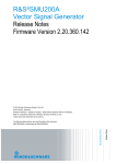
All of these sequences (of maximum length) are generated by means of N-stage shift
registers with appropriate feedback via an EXOR gate (modulo-2 addition).
The following figure provides an overview of the Fibonacci implementation principle
(PRBS11 according to [11]) used by the CDM-Toolbox PRBS generator.
PRBS11 Generator
1
E
X
O
R
g11
g2
PRBS
g0
PRBS
10
Seed1 (e.g: 1
1)
1
1
2
1
0
1
1
1)
All CDM-Toolbox PRBS generator implementations use a seed (initial fill) of ‘All 1’. This initial fill
comprises the first N bits output from the generator (N x 1).
Figure 23: Data Sources – PRBS Generator Overview (Example PRBS11)
1GP96_6E
Rohde & Schwarz
CDM-Toolbox
29
List Management Dialog
Data List Management
Data File:
Sometimes users have ASCII data files on hand containing data bits to be converted
into an R&S data list file. These users should select the data source ‘Data-file bin’
or ‘Data-file hex’
1
3
4
2
Figure 24: Data Input – Data Source Section (Data file)
In this mode of operation the user can select data files (*.txt or *.dm_iqda) by
pressing the ‘Select Data File’ button.
The name of each successfully loaded data file is shown in a related ‘Data file
name’ box and the file content is parsed by the CDM-Toolbox for contained 0/1 values
(Data-file bin) or for contained hex characters 0…F (Data-file hex). All determined bits
are import to the data list immediately.
Please keep in mind that the CDM-Toolbox does not include any means to differentiate
between data bits and e.g. header data which may also be part of the imported ASCII
file. Therefore it is recommended to clip/remove any header part prior to the data file
import. Otherwise 0/1 values or hexadecimal characters which are eventually used in
the header part are treated as data bits which would result in falsified data lists and
sometimes very interesting test results.
For applications which require a data list containing date from different sources the
append mode has to be activated via the related ‘Append ON‘ button
(Available/enabled only if already any data was added to the data list).
Example: In the figure above the data file ‘GPSNav.txt’ was selected via the ‘Select
Data File’ button. All contained data bits were assigned to the data list.
After these actions the ‘Append ON’ button was automatically enabled since now
data is available within the data list. The append mode was enabled by pressing the
‘Append ON’ button, which is indicated by the green indicator sign. Afterwards further
data of any available data source may be appended to the data list.
Data List:
Sometimes an already existing R&S data list file shall be:
Modified (toggling of bits e.g. simulate bit errors)
Extended by additional data bits
Appended to other data bits
Evaluated (Binary file content is unknown)
Transferred quick and easy to a R&S VSG
To foster all of these scenarios the CDM-Toolbox supports the import of data list files.
1
3
4
2
Figure 25: Data Input – Data Source Section (Data list)
1GP96_6E
Rohde & Schwarz
CDM-Toolbox
30
List Management Dialog
Data List Management
For the import of data list files the data source ‘Data list’ has to be selected.
Thereafter the user can select a data list file (*.dm_iqd) by pressing the ‘Select
Data List’ button.
The name of a successfully loaded data list file is shown in the related ‘Import-Data
list file name’ box but also in the ‘Export-Data list file name’ box of the ‘Data List’
section (see chapter 4.2.2). The binary file content is immediately parsed, imported
and shown in the data list section.
Please keep in mind that the CDM-Toolbox performs some consistency checks of the
data list file and the included header tags to evaluate if the selected data list file is
compliant with the R&S data list file specification (see chapter 1.1.1). Therefore to
avoid data list files to become invalid it is strictly recommended not to modify the binary
data list files with any other file editor or tool then the CDM-Toolbox.
For applications which require a data list containing date from different sources the
append mode has to be activated via the related ‘Append ON‘ button
(Available/enabled only if already any data was added to the data list).
Example: The figure above demonstrates the settings after a data list file named
‘DL250M.dm_iqd’ was appended to data bits already included in the data list.
Since the data list contains at least data bits originating from two data sources and
thus appending has taken place the ‘Append OFF’ button which would allow to switch
off the append mode is disabled.
4.1.2 Data List
The ‘Data List’ section visualizes the data list bits in different shapes and provides all
means to modify, save/export and transfer the data list.
2
3
6
4
7
1
8
5
9
Figure 26: Data List Management – Data List Section
1GP96_6E
Rohde & Schwarz
CDM-Toolbox
31
List Management Dialog
Data List Management
The content of the R&S data list file ‘Comment’ tag (see chapter 1.1.1 for details) is
defined within the ‘Comment’ box. By default the ‘Auto Comment’ mode is activated
which assures that comments are generated automatically by the CDM-Toolbox based
on the specified ‘Modulation Type’ and ‘Data Source’.
In contrast the ‘Manual Comment’ mode is selected after activation of the append
mode (see chapter 4.1.1) or may be selected by checking the box located above the
‘Comment’ box to allow user specific comments.
To keep track with the number of bits contained in the data list, which is of special
interest in case of activated data list append mode, the ‘Total number of bits’ is
displayed.
Only a portion of 500 data bits of the data list is shown at once to ease the handling of
(huge) data lists. To display the data list cells of interest the related ‘Cell offset’ has
to be specified by a number of symbols or bytes, based on the currently selected data
list format.
The data bits can be displayed in different ‘Data List Formats’:
Bits per symbol (depends on the selected modulation type, see chapter 4.1.1.1)
Byte-wise (binary)
Byte-wise (hexadecimal)
The bit content of each ‘Data list cell’ (Symbol or byte) may be altered by the user
if needed by selecting a certain cell via a double click with the mouse. This functionality
may be helpful if a certain amount of bits have to be toggled to simulate a specific bit
error rate (fault insertion).
An indicator sign within the total bit count box informs about the actual data list
processing status:
Data List – Processing Status Indicator
Indicator
Meaning
Append mode OFF: Data list is empty
Append mode ON: Data list contains only first portion of data
Data bits from selected data source are currently added to the data list.
Data list contains data bits and is thus ready for data modification
and/or data export.
Table 16: Data List – Processing Status Indicator
After the data bits within the data list are in the required shape the data list can be
saved on any mass memory available on the PC running the CDM-Toolbox by
pressing the ‘Save Data List’ button. By default the data list is stored in the R&S
data list format with ASCII header, binary data and the file extension *.dm_iqd.
If the user wants to export the data list in a plain ASCII file format (e.g. for further
usage by other software tools) the ‘ASCII’ mode has to be activated by checking the
related box. With this mode activated, the data list content without any header tag is
stored in an ASCII file with file extension *.dm_iqda. Please keep in mind that this
type of data list file cannot be transferred to the R&S VSG by the CDM-Toolbox.
The name of the data list file specified by the user is displayed in the ‘Export-Data
list file name’ box.
Instantly after successful export of an R&S data list the ‘Transfer Data List’ button
is enabled if an R&S VSG is already assigned to the CDM-Toolbox (see chapter 3.2).
Assuming that this is the case the data list file can be directly transferred to a specific
directory of the assigned VSG.
1GP96_6E
Rohde & Schwarz
CDM-Toolbox
32
List Management Dialog
Data List Management
Additionally the data list file name is also appended to the data list selection box
available on the ‘Path A/B’ tabs of the CDM Toolbox ‘Main Window’ (see chapter 3.4)
to allow an immediate selection/activation of the data list file.
Data List – VSG Directory
VSG Type
Data List Directory
SMW, SMBV
SMU, SMATE, SMJ
/var/user/DataLists
D:\DataLists
Table 17: Data List – VSG Directory
1GP96_6E
Rohde & Schwarz
CDM-Toolbox
33
List Management Dialog
Control List Management
4.2 Control List Management
The control list management tab is split into two sections, one ‘Data Input’ section
to specify the input parameters to be used for the control list creation and a
‘Control List‘ section to specify the content of the supported control list tags and to
modify (if applicable), save and transfer a generated control list.
1
2
Figure 27: CDM-Toolbox – Control List Management Dialog
1GP96_6E
Rohde & Schwarz
CDM-Toolbox
34
List Management Dialog
Control List Management
4.2.1 Data Input
The ‘Data Input’ section provides all functions to specify the control list (length and
data source). First of all the ‘List length’ specific settings have to be made further on
the ‘Data Source’ has to be selected.
4.2.1.1
List Length
In general the control list length, which is specified by a number of symbols (not bits!),
determines the periodicity of the entire control list.
The CDM-Toolbox supports two modes to specify the control list length which can be
selected by the ‘List length mode’ box. In the following the different modes are
introduced:
Separate:
After selection of the list length mode ‘Separate’ the length of the control list can be
specified user specific by simply modifying the ‘List length’ entry box.
2
1
Figure 28: Data Input – List Length Section (Separate)
Coupled:
If a control list is specified and used in parallel with a data list the list length mode
‘Coupled’ should be selected.
2
1
Figure 29: Data Input – List Length Section (Coupled)
In this mode of operation the control list length is directly coupled with the length of the
data list which is currently under construction.
1GP96_6E
Rohde & Schwarz
CDM-Toolbox
35
List Management Dialog
Control List Management
4.2.1.2
Data Sources
The data sources used to provide the control information to be put into the control list
can be selected by the ‘Data Source’ box. In the following the different data
sources are shown:
Manual:
The data source type ‘Manual’ should be selected by the user if a new control list
has to be setup from the scratch. After selection of this mode the required control
information has to be provided manually via the ‘Control List’ section (for details see
chapter 4.2.2).
1
Figure 30: Data Input – Data Source Section (Manual)
Control List:
Sometimes an already existing R&S control list file shall be:
Modified
Extended by additional tags (e.g. markers)
Evaluated
Transferred quick and easy to a R&S VSG
To foster all of these scenarios the CDM-Toolbox supports the import of control list
files.
1
3
2
Figure 31: Data Input – Data Source Section (Control list)
For the import of control list files the data source ‘Control list’ has to be selected.
Thereafter the user can select a data list file (*.dm_iqc) by pressing the ‘Select Ctrl
List’ button.
The name of a successfully loaded control list file is shown in the related ‘ImportControl list file name’ box
Please keep in mind that the CDM-Toolbox performs some consistency checks of the
control list file and the included tags to evaluate if the selected control list file is
compliant with the R&S control list file specification (see chapter 1.1.2). Therefore to
avoid control list files to become invalid it is strictly recommended not to manipulate the
files with any other file editor or tool then the CDM-Toolbox.
Example: The figure above demonstrates the settings after a control list file named
‘CL-10000-3.dm_iqc’ was successfully imported.
1GP96_6E
Rohde & Schwarz
CDM-Toolbox
36
List Management Dialog
Control List Management
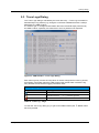
4.2.2 Control List
The ‘Control List’ section visualizes the control list tag definition (see chapter 1.1.2 for
details) and provides all means to modify, save/export and transfer the control list.
2
1
6
3
4
7
5
8
Figure 32: Control List Management – Control List Section
All control list tags (with exception of the ‘Comment’ tag) which shall always be
configured have to be activated via the related ‘Activation’ checkbox first. The
content of the ‘Comment’ tag is defined within the ‘Comment’ box. All other control
tags are specified in the related tag specific box by using the control list syntax. Based
on this syntax a single control slope is defined by the symbol number followed by
a colon and the binary control signal level (0/1). If several control slopes have
to be assigned to a certain tag they have to be separated by a semicolon.
Example: The tags shown in the control list section above are imported from a
control list file named CL-MSK-16.dm_iqc.
MARKER tag 1 is set to high at symbol 0. The MARKER tag 2 has several control
slops. It is set to high at symbol 50 and 60 and back to low at symbol 55 and 90.
MARKER tag 3 was newly added. By mistake the tag is set to low at symbol 100.
Since a control list length of ≤100 is specified a warning symbol shows up and the
‘Save Ctrl List’ button is disabled. MARKER tag 4 remains unused.
The BURST tag specifies that the RF signal has to be activated at symbol 50 and
deactivated at symbol 90. According to the LEVATT tag an additional attenuation has
to be applied on the RF burst level starting from symbol 50 till symbol 55.
The CW MODE tag and the HOP tag remain unused.
The CDM-Toolbox performs some basic syntax checks of any created/modified control
tag to prevent the generation of control lists which are not in accordance with the
specified R&S control list syntax. Therefore if any severe syntax violation is detected
1GP96_6E
Rohde & Schwarz
CDM-Toolbox
37
List Management Dialog
Control List Management
the current control tag content is deleted. If the defined symbol number exceeds the
specified control list length a Warning symbol shows up and the ‘Save Ctrl
List’ button is disabled.
After the control tags are configured as required for a certain test application the
control list can be saved on any mass memory available on the PC running the CDMToolbox by pressing the ‘Save Ctrl List’ button. The control list is stored in the R&S
control list format and the file extension *.dm_iqc.
The name of the control list file specified by the user is displayed in the ‘ExportControl list file name’ box.
Instantly after successful export of an R&S control list the ‘Transfer Ctrl List’ button
is enabled if an R&S VSG is already assigned to the CMD-Toolbox (see chapter 3.2).
Assuming that this is the case the control list file is transferred to a specific directory of
the assigned VSG.
Additionally the control list file name is also appended to the control list selection box
available on the ‘Path A/B’ tabs of the CDM Toolbox ‘Main Window’ (see chapter 3.4)
to allow an immediate selection/activation of the control list file.
Control List – VSG Directory
VSG Type
Data List Directory
SMW, SMBV
SMU, SMATE, SMJ
/var/user/ControlLists
D:\ControlLists
Table 18: Control List – VSG Directory
1GP96_6E
Rohde & Schwarz
CDM-Toolbox
38
Auxiliary Dialogs
Instrument Management Dialog
5 Auxiliary Dialogs
Besides the important ‘List Management’ dialog of the CDM-Toolbox several other
dialogs are available to control the CDM-Toolbox behavior and interaction with
connected R&S VSGs.
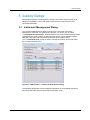
5.1 Instrument Management Dialog
The ‘Instrument Management’ dialog is shown by the menu bar Instrument →
Management command. It is split into two sections, one section, the so called
‘Instrument Announcement’, offers a bundle of functions to determine R&S VSGs
reachable by the CDM-Toolbox via the supported remote control interfaces (GPIB,
USB and LAN) and to announce these generators to the CDM-Toolbox.
The ‘Instrument Pool’ section is used to manage the already announced VSGs,
the so called instrument pool.
1
2
Figure 33: CDM-Toolbox – Instrument Management Dialog
The following paragraphs provide a detailed explanation of the available instrument
announcement and instrument pool features and their usage.
1GP96_6E
Rohde & Schwarz
CDM-Toolbox
39
Auxiliary Dialogs
Instrument Management Dialog
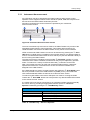
5.1.1 Instrument Announcement
Any VSG which has to be assigned to the CDM-Toolbox to allow remote control
operation via the supported remote control interfaces (GPIB, USB and LAN) has to be
announced to the CDM-Toolbox instrument pool first.
All means required for the announcement are provided by the ‘Instrument
Announcement’ section.
2
1
5
3
4
6
Figure 34: Instrument Announcement Section
The most convenient way to announce VSGs to the CDM-Toolbox is by means of the
integrated remote interface scan functionality. This feature allows searching for
certain/all VSGs connected to the CDM-Toolbox via any remote control interface.
VSGs connected to CDM-Toolbox via LAN can be searched by pressing the ‘Scan
LAN’ button if a DNS server is available in the scanned network. This button initiates a
scan for connected R&S VSGs within the lPv4 subnet (only the first detected subnet) of
the PC running the CDM-Toolbox.
The search process is controlled via the provided ‘Hostname’ specifier. If not all
characters of the VSG’s hostname are well known they may be replaced by question
marks. To search for a variety of VSGs the wild-card (*) character can be used.
After a successful LAN scan all VSGs with a hostname fitting with the ‘Hostname’
specifier are listed in the ‘Instrument Pool’ section and are thus available to be
assigned to the CDM-Toolbox.
If the GPIB interface is used to remotely interact with VSGs the ‘Scan GPIB’ button
has to be pressed to search the GPIB interface 0 (GPIB0) for any connected R&S
VSG. All detected R&S VSGs are listed in the ‘Instrument Pool’ section.
To search for R&S VSGs connected to USB ports 0-9 of the PC running the CDMToolbox the ‘Scan USB’ button has to be pressed. Any detected R&S VSG is listed
in the ‘Instrument Pool’ section.
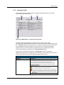
If a certain VSG must not be announced by an automatic interface scan but manually
this can be done by providing an appropriate interface specific ‘Resource
Specifier’ followed by pressing the ‘Add Manually’ button.
Add Manually – Resource Specifier
Interface
Resource Specifier
GPIB
USB
LAN
VISA Resource String (e.g. GPIB0::29::INSTR)
VISA Resource String (e.g. USB0::0x0AAD:0x005F:257839::INSTR)
VISA Resource String (e.g. TCPIP0::rssmw200a100957::INSTR)
Hostname (e.g. rssmw200a100957)
IP-Address (e.g. 10.111.12.60)
Table 19: Add Manually – Resource Specifier
1GP96_6E
Rohde & Schwarz
CDM-Toolbox
40
Auxiliary Dialogs
Instrument Management Dialog
5.1.2 Instrument Pool
The ‘Instrument Pool’ section is used to manage all R&S VSGs which are already
announced to the CDM-Toolbox.
1
2
3
4
Figure 35: CDM-Toolbox – Instrument Pool Section
Several functions are available to deal with the pool of announced VSGs.
To initiate an immediate verification of the connection status of all VSGs within the pool
the ‘Refresh’ button has to be pressed. If a connection status change is discovered
the VSG related ‘Connection Status’ icon (see Table 20) is changed accordingly.
Certain VSGs can be removed from the instrument pool by selecting them with a
mouse click followed by pressing the ‘Delete Selected’ button.
To clear the overall instrument pool the ‘Delete All’ button must be used.
Besides these functions to manage the VSGs belonging to the instrument pool several
connection status and instrument related parameters are provided:
Instrument Pool – Instrument and Connection Status Parameters
Column
Parameter
Instrument
Enabling status checkbox:
-Checked: VSG is enabled for remote control by the CDM-Toolbox
-Unchecked: VSG is not allowed to be remote controlled
Note: The remote control connection to a VSG which is currently
assigned to the CDM-Toolbox is promptly terminated if the enable
check box is unchecked.
Connection status icon:
: VSG is available and may be remote controlled
: VSG is currently assigned to the CDM toolbox for remote control
: Connection to VSG is lost (e.g. VSG switched of or interface cable
unplugged). This status information is only provided for manually
added VSGs.
VSG type and serial number
1GP96_6E
Rohde & Schwarz
CDM-Toolbox
41
Auxiliary Dialogs
Color Settings Dialog
Instrument Pool – Instrument and Connection Status Parameters
Column
Parameter
Interface used to connect the VSG
VISA resource string1
VSG FW version1
Comment
Information how a certain VSG was added to the instrument pool
1) Will by shown/hide by pressing the grey triangle in the ‘Instrument’ column
Interface
Table 20: Instrument Pool – Parameters
5.2 Color Settings Dialog
The ‘Color Settings’ dialog is activated by the menu bar Settings → Color command.
This dialog is intended to enable the user to slightly modify the GUI appearance in
accordance with the personal preferences.
Figure 36: CDM-Toolbox – Color Settings Dialog
Note: Any modification of the color settings are saved in a color settings file which is
applied at any CDM-Toolbox restart (see chapter 2.4.3 for details).
1GP96_6E
Rohde & Schwarz
CDM-Toolbox
42
Auxiliary Dialogs
Trace Logs Dialog
5.3 Trace Logs Dialog
The ‘Trace Logs’ dialog is activated by the menu bar Help → Trace Logs command or
automatically if any problem (e.g. during the connection establishment with a VSG) is
detected by the CDM-Toolbox.
It is useful to get background information about the functional steps performed by
the CDM-Toolbox, especially if a certain action was not performed as expected.
2
3
1
Figure 37: CDM-Toolbox – Trace Logs Dialog
Each trace log entry consists of a flag which is used to categorize the trace log entries,
a timestamp, information about the CDM-Toolbox SW module which caused the log
entry and last but not least the logging information itself.
Trace Log – Flags
Flag
Meaning
Any successful action
Any successful action
(extended information, ‘--debug’ parameter appended
Error
Table 21: Trace Log – Flags
To clear the ‘Trace Log’ dialog (e.g. to get rid of outdated entries) the ‘Clear’ button
has to be pressed.
1GP96_6E
Rohde & Schwarz
CDM-Toolbox
43
Auxiliary Dialogs
Trace Logs Dialog
The ‘Copy’ button must be used if the content of the ‘Trace Log’ dialog has to be
transferred to the clipboard. If it is required to save the trace log entries continuously
within a file the CDM-Toolbox has to be started with applied ‘--filedebug' command
line parameter. The created log file is stored in the ‘Users’ directory:
e.g.: C:\Users\<UserName>\CDMToolbox.log
To extend the shown logging information (further details) the ‘--debug' parameter has
to be appended.
Note: This parameters should only be used for debugging purposes (e.g. to provide
additional information to the R&S customer support in case of malfunctions), since it
slows down the application significantly.
For details how to apply command line parameter see chapter 2.4.1.1.
1GP96_6E
Rohde & Schwarz
CDM-Toolbox
44
Abbreviations
Trace Logs Dialog
6 Abbreviations
ASK
CDM
CW
FSK
GPIB
LAN
PN
PRBS
PSK
QAM
SCPI
USB
VISA
VSG
Amplitude Shift Keying
Custom Digital Modulation
Continuous Wave
Frequency Shift Keying
General Purpose Interface Bus
Local Area Network
Pseudo Noise
Pseudo Random Bit Sequence
Phase Shift Keying
Quadrature Amplitude Modulation
Standard Commands for Programmable Instrumentation
Universal Serial Bus
Virtual Instrument Software Architecture
Vector Signal Generator
7 References
Manuals:
[1]
[2]
[3]
[4]
[5]
R&S, SMW200A User Manual
R&S, SMU200A Operating Manual
R&S, SMATE200A Operating Manual
R&S, SMJ100A Operating Manual
R&S, SMBV100A Operating Manual
Application Notes:
[6]
[7]
[8]
R&S, 1GP99, ARB Toolbox Plus
R&S, MapWiz, Modulation mapping wizard
R&S, FiltWiz, Shaping filter design wizard
Standards:
[9]
[10]
[11]
1GP96_6E
CCITT Recommendation O.151, 10/1992
CCITT Recommendation O.152, 10/1992
CCITT Recommendation O.153, 10/1992
Rohde & Schwarz
CDM-Toolbox
45
Appendix
Release Notes
8 Appendix
8.1 Release Notes
8.1.1 Version 1.4.0 (Initial release)
Released: October 2013
Functional improvements:
Not applicable
Fixed Issues:
Not applicable
8.1.2 Version 1.5.0
Released: January 2014
Functional improvements:
Modulation type 4096QAM added (SMW only)
Maximum data list length extended to 250 MBit
Fixed Issues:
Modulation type specific maximum symbol rates corrected
8.1.3 Version 1.5.1
Released: June 2014
Functional improvements:
New SMW hardware options added to the option list
New SMW software options added to option list
VISA read buffer size (VI_READ_BUF) increased to 8192 byte to allow the query of
long option strings
Fixed Issues:
The control list length calculation with activated ‘Coupled’ mode is now based on
the total number of data symbols within the current data list
1GP96_6E
Rohde & Schwarz
CDM-Toolbox
46
Appendix
Release Notes
8.1.4 Version 1.6.0
Released: August 2014
Functional improvements:
Support of all modulation type specific parameters (e.g. modulation depth)
User defined modulation mappings (*.vam)
User defined shaping filters (*.vaf)
Import of hex based data files
8.1.5 Version 1.6.1
Released: December 2014
Functional improvements:
New SMW hardware options added to the option list
New SMW and SMBV software options added to option list
Fixed Issues:
User Modulation and User Filter file selection issue corrected
Data list file import issue corrected
8.1.6 Version 1.7.0
Released: July 2015
Functional improvements:
LAN scan functionality optimized for networks without DNS and/or DHCP server
8.1.7 Version 1.7.5702.3657
Released: August 2015
Functional improvements:
New Windows installer
1GP96_6E
Rohde & Schwarz
CDM-Toolbox
47
Ordering Information
Release Notes
9 Ordering Information
Please visit the Rohde & Schwarz product websites at www.rohde-schwarz.com for
ordering information on the following Rohde & Schwarz products:
1GP96_6E
®
R&S SMW200A vector signal generator
®
R&S SMBV100A vector signal generator
®
R&S SMU200A vector signal generator
®
R&S SMATE200A vector signal generator
®
R&S SMJ100A vector signal generator
Rohde & Schwarz
CDM-Toolbox
48
About Rohde & Schwarz
Rohde & Schwarz is an independent group
of companies specializing in electronics. It is
a leading supplier of solutions in the fields of
test and measurement, broadcasting,
radiomonitoring and radiolocation, as well as
secure communications. Established more
than 75 years ago, Rohde & Schwarz has a
global presence and a dedicated service
network in over 70 countries. Company
headquarters are in Munich, Germany.
Environmental commitment
● Energy-efficient products
● Continuous improvement in
environmental sustainability
● ISO 14001-certified environmental
management system
Regional contact
Europe, Africa, Middle East
+49 89 4129 12345
[email protected]
North America
1-888-TEST-RSA (1-888-837-8772)
[email protected]
Latin America
+1-410-910-7988
[email protected]
Asia/Pacific
+65 65 13 04 88
[email protected]
China
+86-800-810-8228 /+86-400-650-5896
[email protected]
This application note and the supplied
programs may only be used subject to the
conditions of use set forth in the download
area of the Rohde & Schwarz website.
R&S® is a registered trademark of Rohde & Schwarz
GmbH & Co. KG; Trade names are trademarks of the
owners.
Rohde & Schwarz GmbH & Co. KG
Mühldorfstraße 15 | D - 81671 München
Phone + 49 89 4129 - 0 | Fax + 49 89 4129 – 13777
www.rohde-schwarz.com