1
2600AS-900-01 (B - September 2008).qxp
10/9/08
3:38 PM
Page 1
www.keithley.com
www.keithley.com
Series 2600A System SourceMeter®
Series 2600A System SourceMeter®
User’s Manual
User’s Manual
2600AS-900-01 Rev. B / September 2008
2600AS-900-01 Rev. B / September 2008
A
G R E A T E R
M E A S U R E
O F
C O N F I D E N C E
A
G R E A T E R
M E A S U R E
O F
C O N F I D E N C E
WARRANTY
Keithley Instruments, Inc. warrants this product to be free from defects in material and workmanship for a period of
one (1) year from date of shipment.
Keithley Instruments, Inc. warrants the following items for 90 days from the date of shipment: probes, cables,
software, rechargeable batteries, diskettes, and documentation.
During the warranty period, Keithley Instruments will, at its option, either repair or replace any product that proves
to be defective.
To exercise this warranty, write or call your local Keithley Instruments representative, or contact
Keithley Instruments headquarters in Cleveland, Ohio. You will be given prompt assistance and return instructions.
Send the product, transportation prepaid, to the indicated service facility. Repairs will be made and the product
returned, transportation prepaid. Repaired or replaced products are warranted for the balance of the original
warranty period, or at least 90 days.
LIMITATION OF WARRANTY
This warranty does not apply to defects resulting from product modification without Keithley Instruments’ express
written consent, or misuse of any product or part. This warranty also does not apply to fuses, software,
non-rechargeable batteries, damage from battery leakage, or problems arising from normal wear or failure to follow
instructions.
THIS WARRANTY IS IN LIEU OF ALL OTHER WARRANTIES, EXPRESSED OR IMPLIED, INCLUDING ANY
IMPLIED WARRANTY OF MERCHANTABILITY OR FITNESS FOR A PARTICULAR USE. THE REMEDIES
PROVIDED HEREIN ARE BUYER’S SOLE AND EXCLUSIVE REMEDIES.
NEITHER KEITHLEY INSTRUMENTS, INC. NOR ANY OF ITS EMPLOYEES SHALL BE LIABLE FOR ANY
DIRECT, INDIRECT, SPECIAL, INCIDENTAL, OR CONSEQUENTIAL DAMAGES ARISING OUT OF THE USE
OF ITS INSTRUMENTS AND SOFTWARE, EVEN IF KEITHLEY INSTRUMENTS, INC. HAS BEEN ADVISED IN
ADVANCE OF THE POSSIBILITY OF SUCH DAMAGES. SUCH EXCLUDED DAMAGES SHALL INCLUDE, BUT
ARE NOT LIMITED TO: COST OF REMOVAL AND INSTALLATION, LOSSES SUSTAINED AS THE RESULT OF
INJURY TO ANY PERSON, OR DAMAGE TO PROPERTY.
A
G R E A T E R
M E A S U R E
O F
C O N F I D E N C E
Keithley Instruments, Inc.
Corporate Headquarters • 28775 Aurora Road • Cleveland, Ohio 44139
440-248-0400 • Fax: 440-248-6168 • 1-888-KEITHLEY (1-888-534-8453) • www.keithley.com
3/07
Series 2600A
System SourceMeter® Instruments
User’s Manual
©2008, Keithley Instruments, Inc.
All rights reserved.
Any unauthorized reproduction, photocopy, or use the information herein, in whole or in part without the prior written
approval of Keithley Instruments, Inc. is strictly prohibited.
TSP, TSP-Link, and TSP-Net are trademarks of Keithley Instruments, Inc.
All Keithley Instruments product names are trademarks or registered trademarks of Keithley Instruments, Inc.
Other brand names are trademarks or registered trademarks of their respective holders
Cleveland, Ohio, U.S.A.
Document Number:
2600AS-900-01 Rev. B / September 2008
Safety Precautions
The following safety precautions should be observed before using this product and any associated instrumentation. Although some
instruments and accessories would normally be used with non-hazardous voltages, there are situations where hazardous conditions may
be present.
This product is intended for use by qualified personnel who recognize shock hazards and are familiar with the safety precautions required
to avoid possible injury. Read and follow all installation, operation, and maintenance information carefully before using the product. Refer
to the user documentation for complete product specifications.
If the product is used in a manner not specified, the protection provided by the product warranty may be impaired.
The types of product users are:
Responsible body is the individual or group responsible for the use and maintenance of equipment, for ensuring that the equipment is
operated within its specifications and operating limits, and for ensuring that operators are adequately trained.
Operators use the product for its intended function. They must be trained in electrical safety procedures and proper use of the instrument.
They must be protected from electric shock and contact with hazardous live circuits.
Maintenance personnel perform routine procedures on the product to keep it operating properly, for example, setting the line voltage or
replacing consumable materials. Maintenance procedures are described in the user documentation. The procedures explicitly state if the
operator may perform them. Otherwise, they should be performed only by service personnel.
Service personnel are trained to work on live circuits, perform safe installations, and repair products. Only properly trained service
personnel may perform installation and service procedures.
Keithley Instruments products are designed for use with electrical signals that are rated Measurement Category I and Measurement
Category II, as described in the International Electrotechnical Commission (IEC) Standard IEC 60664. Most measurement, control, and
data I/O signals are Measurement Category I and must not be directly connected to mains voltage or to voltage sources with high transient
over-voltages. Measurement Category II connections require protection for high transient over-voltages often associated with local AC
mains connections. Assume all measurement, control, and data I/O connections are for connection to Category I sources unless otherwise
marked or described in the user documentation.
Exercise extreme caution when a shock hazard is present. Lethal voltage may be present on cable connector jacks or test fixtures. The
American National Standards Institute (ANSI) states that a shock hazard exists when voltage levels greater than 30V RMS, 42.4V peak,
or 60V DC are present. A good safety practice is to expect that hazardous voltage is present in any unknown circuit before measuring.
Operators of this product must be protected from electric shock at all times. The responsible body must ensure that operators are
prevented access and/or insulated from every connection point. In some cases, connections must be exposed to potential human contact.
Product operators in these circumstances must be trained to protect themselves from the risk of electric shock. If the circuit is capable of
operating at or above 1000V, no conductive part of the circuit may be exposed.
Do not connect switching cards directly to unlimited power circuits. They are intended to be used with impedance-limited sources. NEVER
connect switching cards directly to AC mains. When connecting sources to switching cards, install protective devices to limit fault current
and voltage to the card.
Before operating an instrument, ensure that the line cord is connected to a properly-grounded power receptacle. Inspect the connecting
cables, test leads, and jumpers for possible wear, cracks, or breaks before each use.
11/07
When installing equipment where access to the main power cord is restricted, such as rack mounting, a separate main input power
disconnect device must be provided in close proximity to the equipment and within easy reach of the operator.
For maximum safety, do not touch the product, test cables, or any other instruments while power is applied to the circuit under test.
ALWAYS remove power from the entire test system and discharge any capacitors before: connecting or disconnecting cables or jumpers,
installing or removing switching cards, or making internal changes, such as installing or removing jumpers.
Do not touch any object that could provide a current path to the common side of the circuit under test or power line (earth) ground. Always
make measurements with dry hands while standing on a dry, insulated surface capable of withstanding the voltage being measured.
The instrument and accessories must be used in accordance with its specifications and operating instructions, or the safety of the
equipment may be impaired.
Do not exceed the maximum signal levels of the instruments and accessories, as defined in the specifications and operating information,
and as shown on the instrument or test fixture panels, or switching card.
When fuses are used in a product, replace with the same type and rating for continued protection against fire hazard.
Chassis connections must only be used as shield connections for measuring circuits, NOT as safety earth ground connections.
If you are using a test fixture, keep the lid closed while power is applied to the device under test. Safe operation requires the use of a lid
interlock.
If a
The
screw is present, connect it to safety earth ground using the wire recommended in the user documentation.
!
symbol on an instrument indicates that the user should refer to the operating instructions located in the user documentation.
The
symbol on an instrument shows that it can source or measure 1000V or more, including the combined effect of normal and
common mode voltages. Use standard safety precautions to avoid personal contact with these voltages.
The
symbol on an instrument shows that the surface may be hot. Avoid personal contact to prevent burns.
The
symbol indicates a connection terminal to the equipment frame.
If this
symbol is on a product, it indicates that mercury is present in the display lamp. Please note that the lamp must be properly
disposed of according to federal, state, and local laws.
The WARNING heading in the user documentation explains dangers that might result in personal injury or death. Always read the
associated information very carefully before performing the indicated procedure.
The CAUTION heading in the user documentation explains hazards that could damage the instrument. Such damage may invalidate the
warranty.
Instrumentation and accessories shall not be connected to humans.
Before performing any maintenance, disconnect the line cord and all test cables.
To maintain protection from electric shock and fire, replacement components in mains circuits - including the power transformer, test leads,
and input jacks - must be purchased from Keithley Instruments. Standard fuses with applicable national safety approvals may be used if
the rating and type are the same. Other components that are not safety-related may be purchased from other suppliers as long as they
are equivalent to the original component (note that selected parts should be purchased only through Keithley Instruments to maintain
accuracy and functionality of the product). If you are unsure about the applicability of a replacement component, call a Keithley Instruments
office for information.
To clean an instrument, use a damp cloth or mild, water-based cleaner. Clean the exterior of the instrument only. Do not apply cleaner
directly to the instrument or allow liquids to enter or spill on the instrument. Products that consist of a circuit board with no case or chassis
(for example, a data acquisition board for installation into a computer) should never require cleaning if handled according to instructions.
If the board becomes contaminated and operation is affected, the board should be returned to the factory for proper cleaning/servicing.
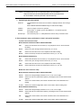
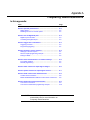
Table of Contents
Section
1
Topic
Page
Front and Rear Panel Operation ........................................................ 1-1
Front and rear panel familiarization ............................................................ 1-2
Front panel summaries......................................................................... 1-2
Rear panel summaries ......................................................................... 1-2
Model 2601A/2602A and Model 2611A/2612A rear panels ................. 1-5
Model 2635A/2636A rear panels.......................................................... 1-7
What are the source-measure capabilities? ............................................... 1-9
Model 2601A and Model 2602A ........................................................... 1-9
Model 2611A and Model 2612A ........................................................... 1-9
Model 2635A and Model 2636A ........................................................... 1-9
How do I power-up the instrument?.......................................................... 1-10
How do I make measurements? ............................................................... 1-11
How do I use the reading buffer?.............................................................. 1-15
2
Remote Operation ................................................................................. 2-1
How do I use the remote interface?............................................................ 2-2
Connect to the interface ....................................................................... 2-2
Configure the interface......................................................................... 2-2
Working with the web interface................................................................... 2-8
How to use the Virtual Front Panel....................................................... 2-9
TSP Express............................................................................................... 2-9
TSB embedded........................................................................................... 2-9
Issuing ICL commands....................................................................... 2-10
How do I use Test Script Builder?............................................................. 2-11
How do I use TSB to make measurements? ............................................ 2-14
How do I use other programs? ................................................................. 2-17
Using LabVIEW .................................................................................. 2-17
Using Visual Basic.............................................................................. 2-19
3
Test Script Processor Interaction ...................................................... 3-1
What is a script? ......................................................................................... 3-2
Factory scripts ...................................................................................... 3-2
User scripts .......................................................................................... 3-2
How do I run a script from the front panel?................................................. 3-2
How do I save scripts to the USB flash drive?............................................ 3-3
How do I interact with scripts using Test Script Builder? ............................ 3-4
Running a factory script ....................................................................... 3-4
Modifying a factory script ..................................................................... 3-6
Running the user script ...................................................................... 3-11
Deleting a user script and user tests .................................................. 3-12
How do I use other programs? ................................................................. 3-12
Using LabVIEW .................................................................................. 3-12
Using Visual Basic.............................................................................. 3-14
4
Controlling Multiple Series 2600As (TSP-Link) .............................. 4-1
How do I set up the TSP-Link system?.......................................................
How do I use the expanded system?..........................................................
Accessing resources of TSP-Link nodes .............................................
Running scripts in a TSP-Link system..................................................
4-2
4-3
4-3
4-4
Series 2600A System SourceMeter® Instruments User’s Manual
Table of Contents
Appendix
A
Topic
Page
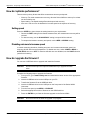
Frequently Asked Questions.............................................................. A-1
How do I optimize performance? ............................................................... A-2
Setting speed....................................................................................... A-2
Disabling auto zero to increase speed ................................................ A-2
How do I upgrade the firmware? ................................................................ A-2
How do I use the Digital I/O port? .............................................................. A-3
Digital I/O port terminals ...................................................................... A-3
Controlling the digital I/O port .............................................................. A-3
How do I trigger other instruments? ........................................................... A-3
Triggering a scanner............................................................................ A-3
Programming triggering ....................................................................... A-4
How do I generate a service request? ....................................................... A-4
Setting up a service request ................................................................ A-4
Service request programming example ............................................... A-4
Polling for SRQs .................................................................................. A-5
How do I store measurements in nonvolatile memory? ............................. A-5
Front panel operation........................................................................... A-5
Remote programming .......................................................................... A-5
How do I stack channels to output higher voltage?.................................... A-6
How do I parallel channels to output higher current?................................. A-7
How do I make contact check measurements? ......................................... A-8
Contact check connections.................................................................. A-8
How do I make low-current measurements?.............................................. A-9
Low-current connections ..................................................................... A-9
Low-current measurement programming example ............................ A-10
Index .................................................................................................... Index-1
ii
2600AS-900-01 Rev. B / September 2008
List of Figures
Section
1
1
1
1
1
1
1
1
2
2
2
2
2
2
2
2
2
2
2
2
2
3
3
3
3
3
3
3
3
3
3
4
Figure
Page
Figure 1-1 Models 2601A, 2611A, 2602A, 2612A, 2635A,
and 2636A front panels.................................................................. 1-2
Figure 1-2 Model 2601A/2602A/2611A/2612A rear panels............................. 1-5
Figure 1-3 Model 2635A and 2636A rear panels ............................................ 1-7
Figure 1-4 Model 2602A/2612A low-noise chassis ground banana jack
and chassis screw ....................................................................... 1-13
Figure 1-4 Model 2636A................................................................................ 1-13
Figure 1-5 Interlock circuit............................................................................. 1-14
Figure 1-6 Display modes ............................................................................. 1-14
Figure 1-7 Buffer display format.................................................................... 1-17
Figure 2-1 GPIB cable..................................................................................... 2-2
Figure 2-2 RS-232 cable ................................................................................. 2-2
Figure 2-3 Computer configuration using the command prompt..................... 2-4
Figure 2-4 Internet protocol (TCP/IP) properties dialog box ........................... 2-6
Figure 2-5 LAN connection ............................................................................. 2-8
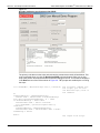
Figure 2-6 Web interface................................................................................. 2-9
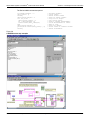
Figure 2-7 Test Script Builder initial startup screen....................................... 2-12
Figure 2-8 Instrument console control icons ................................................. 2-13
Figure 2-9 Select Instrument Resource dialog box ....................................... 2-14
Figure 2-10 Source-measure command sequence in console window
(2601A/2602A version shown)..................................................... 2-15
Figure 2-11 LabVIEW source-measure example block diagram..................... 2-18
Figure 2-12 Visual Basic example user interface ............................................ 2-19
Figure 2-13 Example program test results ...................................................... 2-21
Figure 3-1 Pulse-measure cycle for the PulseVMeasureI function ............... 3-4
Figure 3-2 Importing a factory script project from the Series 2600A............... 3-7
Figure 3-3 KIGeneral project imported into the Test Script Builder ................. 3-8
Figure 3-4 Run configuration example - Main tab shown.............................. 3-10
Figure 3-5 Run configuration example - Script Attributes tab shown ............ 3-11
Figure 3-6 LabVIEW source step example ................................................... 3-13
Figure 3-7 GUI after loading the non-function script (GPIB) ......................... 3-16
Figure 3-8 GUI after running the non-function script (GPIB)......................... 3-17
Figure 3-9 GUI after loading and running the function script (GPIB) ............ 3-18
Figure 3-10 GUI after calling the function (GPIB) ........................................... 3-19
Figure 4-1 TSP-Link connections.................................................................... 4-2
Appendix Figure
A
A
A
A
A
A
A
Title
Figure A-1
Figure A-2
Figure A-3
Figure A-4
Figure A-5
Figure A-6
Figure A-7
Title
Page
Digital I/O port terminals ................................................................ A-3
Triggering a scanner ...................................................................... A-4
Stacking channels for higher voltage ............................................. A-7
Connecting channels in parallel for higher current ........................ A-8
Model 2601A/2602A/2611A/2612A contact check connections ... A-8
Model 2635A/2636A contact check connections ........................... A-9
Model 2635A/2636A low-current connections ............................. A-10
List of Figures
Series 2600A System SourceMeter® Instruments User’s Manual
This page left blank intentionally.
ii
2600AS-900-01 Rev. B / September 2008
List of Tables
Section
1
1
1
1
1
Appendix
A
Table
Title
Table 1-1
Table 1-2
Table 1-3
Table 1-4
Table 1-5
Connectors and triax cable conductors .........................................
Triax connector on ground module ................................................
Model 2601A and 2602A source-measure capabilities .................
Model 2611A and 2612A source-measure capabilities..................
Model 2635A and 2636A source-measure capabilities .................
Table
Table A-1
Page
Title
1-7
1-8
1-9
1-9
1-9
Page
Commands for basic I/O port......................................................... A-3
List of Tables
Series 2600A System SourceMeter® Instruments User’s Manual
This page left blank intentionally.
ii
2600AS-900-01 Rev. B / September 2008
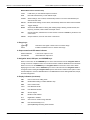
Section 1
Front and Rear Panel Operation
In this section:
Topic
Page
Front and rear panel familiarization .................................................
Front panel summaries..................................................................
Rear panel summaries ..................................................................
Model 2601A/2602A and Model 2611A/2612A rear panels...........
Model 2635A/2636A rear panels ...................................................
1-2
1-2
1-2
1-5
1-7
What are the source-measure capabilities? .................................... 1-9
What are the source-measure capabilities?....................................
Model 2601A and Model 2602A ....................................................
Model 2611A and Model 2612A ....................................................
Model 2635A and Model 2636A ....................................................
1-9
1-9
1-9
1-9
How do I power-up the instrument?.................................................
Connect to line power....................................................................
Turn on power ...............................................................................
Set line frequency..........................................................................
1-10
1-10
1-10
1-10
How do I make measurements? .......................................................
Connect the DUT...........................................................................
Select source and set source level................................................
Set compliance limit ......................................................................
Select measurement function and range.......................................
Turn output on ...............................................................................
Make measurements .....................................................................
Turn output off ...............................................................................
1-11
1-11
1-11
1-11
1-12
1-12
1-12
1-12
How do I use the reading buffer? .....................................................
Connecting the device under test (DUT) .......................................
Set up source and measure functions ...........................................
Configuring the reading buffer .......................................................
Turn on the output .........................................................................
Storing reading buffers ..................................................................
Turn off the output .........................................................................
Recalling readings .........................................................................
1-15
1-15
1-15
1-15
1-16
1-16
1-16
1-16
Section 1: Front and Rear Panel Operation
Series 2600A System SourceMeter® Instruments User’s Manual
Front and rear panel familiarization
Front panel summaries
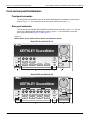
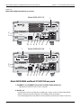
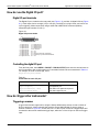
The front panels of the Keithley Instruments Series 2600A System SourceMeter® instrument are
shown in Figure 1-1. The descriptions of the front panel controls follow Figure 1-1.
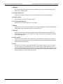
Rear panel summaries
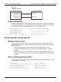
The rear panels of the Models 2601A/2602A and 2611A/2612A are shown in Figure 1-2. The rear
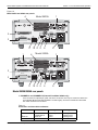
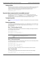
panels of the Models 2635A and 2636A are shown in Figure 1-3. The descriptions of the rear
panel components follow Figure 1-2 and Figure 1-3.
Figure 1-1
Models 2601A, 2611A, 2602A, 2612A, 2635A, and 2636A front panels
Model 2601A and Model 2611A
+/-
MODE
5
4
DIGITS SPEED
POWER
1
2
LOAD
RUN
6
0
REL
FILTER
3
0000
TO E DIT / E
SH
PU
9
LIMIT
R
8
MEAS
TE
CONFIG
7
SRC
N
DISPLAY
PU
R
TO E DIT / E
KEITHLEY SourceMeter
TE
SH
N
2601A SYSTEM SourceMeter®
CURSOR
RANGE
AUTO
RANGE
LOCAL
STORE RECALL
1
TRIG
MENU
EXIT
ENTER
OUTPUT
ON/OFF
4
3
2
5
Model 2602A and Model 2612A
1
1-2
8
9
+/-
SRC
MEAS
LIMIT
MODE
4
5
1
2
LOAD
RUN
TO E DIT / E
SH
PU
POWER
CHANNEL B
7
DIGITS SPEED
R
CONFIG
TE
DISPLAY
N
CHANNEL A
PU
R
TO E DIT / E
KEITHLEY SourceMeter
TE
SH
N
2602A SYSTEM SourceMeter®
6
CURSOR
SRC
MEAS
LIMIT
MODE
RANGE
0
REL
FILTER
3
0000
DIGITS SPEED
REL
FILTER
STORE RECALL
TRIG
MENU
EXIT
AUTO
RANGE
LOCAL
ENTER
2
Return to Section Topics
3
OUTPUT
CHAN
A
ON/OFF
4
CHAN
B
5
2600AS-900-01 Rev. B / September 2008
Series 2600A System SourceMeter® Instruments User’s Manual
Section 1: Front and Rear Panel Operation
NOTE The Models 2601A, 2611A, and 2635A have one SourceMeter
channel (Channel A) and the Models 2602A, 2612A, and 2636A have
two SourceMeter channels (Channel A and Channel B).
1.
Special keys and power switch:
DISPLAY
Toggles between the various source-measure is displayed and the user message
mode.
Selects Models 2602A/2612A/2636A single or dual-channel display.
CONFIG
Used to configure a function or operation.
POWER
Power switch: “In” position (I) turns SourceMeter on, “out” position (O) turns
SourceMeter off (O).
Number keys
The number keys (0-9, +/-, 0000) allow direct numeric entry in the EDIT mode.
2. Source-measure setup, performance control, and special operation:
Top Row: Source-measure setup
Model 2601A/2611A/2635A and Model 2602A/2612A/2636A:
SRC
Channel A: Selects the source function (V or A) and places cursor in the source field
for editing.
MEAS
Channel A: Cycles through measure functions (V, A, Ω or W).
LIMIT
Channel A: Places the cursor in the compliance limit field for editing.
MODE
Channel A: Directly chooses the measurement function (V, A, Ω or W).
Model 2602A/2612A/2636A only:
SRC
Channel B: Selects the source function (V or A) and places cursor in the source field.
MEAS
Channel B: Cycles through measure functions (V, A, Ω or W).
LIMIT
Channel B: Places the cursor in the compliance limit field for editing.
MODE
Channel B: Directly chooses the measurement function (V, A, Ω or W).
Middle Row: Source-measure setup
Model 2601A/2611A/2635A and Model 2602A/2612A/2636A:
DIGITS
Channel A: Changes display resolution to 4-1/2, 5-1/2, or 6-1/2 digits.
SPEED
Channel A: Sets the measurement speed by controlling the A/D converter measurement
aperture.
REL
Channel A: Controls relative, which allows a baseline value to be subtracted from a
reading.
FILTER
Channel A: Controls the digital filter, which can be used to reduce reading noise.
Model 2602A/2612A/2636A only:
DIGITS
Channel B: Changes display resolution to 4-1/2, 5-1/2, or 6-1/2 digits.
SPEED
Channel B: Sets the measurement speed by controlling the A/D converter measurement
aperture.
REL
Channel B: Controls relative, which allows a baseline value to be subtracted from a
reading.
FILTER
Channel B: Controls the digital filter, which can be used to reduce reading noise.
2600AS-900-01 Rev. B / September 2008
Return to Section Topics
1-3
Section 1: Front and Rear Panel Operation
Series 2600A System SourceMeter® Instruments User’s Manual
Bottom Row: Source-measure setup
LOAD
Loads factory or user-defined scripts for execution.
RUN
Runs last selected factory or user-defined scripts.
STORE
Stores readings, source values, and timestamp values in one of two internal buffers per
channel for later recall.
RECALL
Recalls stored readings, source values, and timestamp values from either of the two buffers.
TRIG
Triggers readings.
MENU
Accesses the Main Menu for saving and recalling setups, selecting remote interface, line
frequency, self-tests, serial number and beeper control.
EXIT
Cancels selection, and backs out of menu structure. Used as a LOCAL key to take the unit
out of remote.
ENTER
Accepts selection, moves to next choice or exits menu.
3. Range keys:
and
Selects the next higher or lower source or measure range.
AUTO
Enables or disables source or measure auto range.
4. Output control and LED status indicator:
OUTPUT ON/OFF
Turns source output on or off.
LED indicator
Illuminated when output is on.
5. Navigation wheel, USB port, and CURSOR keys:
When in source edit, use the CURSOR keys for cursor control and then turn the navigation wheel to
change a source or compliance value. The can also be used to enable or disable the source edit mode.
When in a menu, use the CURSOR keys or navigation wheel for menu item cursor control. When
displaying a menu value, use the CURSOR keys for cursor control and turn the navigation wheel to
change the value. Pressing the navigation wheel opens a menu item or selects a menu option or value.
Use the USB port to connect a USB flash drive. The USB flash drive stores reading buffer data, scripts,
and user setup options.
6. Display indicators (not shown):
1-4
EDIT
Unit is in the source editing mode.
ERR
Questionable reading or invalid calibration step.
REM
Unit in remote mode.
TALK
Unit addressed to talk.
LSTN
Unit addressed to listen.
SRQ
Service request.
REL
Relative mode enabled.
FILT
Digital filter is enabled.
AUTO
Auto source or measure range selected.
ARM
Unit armed and ready to run.
*
(asterisk)Readings are being stored in buffer.
Return to Section Topics
2600AS-900-01 Rev. B / September 2008
Series 2600A System SourceMeter® Instruments User’s Manual
Section 1: Front and Rear Panel Operation
Figure 1-2
Model 2601A/2602A/2611A/2612A rear panels
Model 2601A/2611A
1
WARNING:NO INTERNAL OPERATOR SERVICABLE PARTS,SERVICE BY QUALIFIED PERSONNEL ONLY.
CHANNEL A
C
MADE IN
U.S.A.
UL
!
S
CAT I
LO LO G HI G G
US
!
LINE FUSE
SLOWBLOW
LINE RATING
100-240VAC
50, 60Hz
240VA MAX.
3.15A, 250V
RS-232
2
3
S
G HI
LISTED
SourceMeter
4ZA4
DIGITAL I/O
!
LAN
IEEE-488
TSP-Link
R
CAUTION:FOR CONTINUED PROTECTION AGAINST FIRE HAZARD,REPLACE FUSE WITH SAME TYPE AND RATING.
10 4
6 5 7
8
9
Model 2602A/2612A
1
1
WARNING:NO INTERNAL OPERATOR SERVICABLE PARTS,SERVICE BY QUALIFIED PERSONNEL ONLY.
CHANNEL A
!
S
CAT I
LO LO G HI G G
S
HI
G
G G HI G S LO
LO
!
CAT I
CHANNEL B
!
LINE FUSE
SLOWBLOW
3.15A, 250V
RS-232
2
3
LINE RATING
100-240VAC
50, 60Hz
240VA MAX.
MADE IN
U.S.A.
DIGITAL I/O
IEEE-488
S
G HI
!
LAN
NO AUTO-MDIX
TSP-Link
R
CAUTION:FOR CONTINUED PROTECTION AGAINST FIRE HAZARD,REPLACE FUSE WITH SAME TYPE AND RATING.
10 4
6 5 7
8
9
Model 2601A/2602A and Model 2611A/2612A rear panels
1. CHANNEL A and CHANNEL B (Channel B on Model 2602A/2612A only)
Input/output connections for source, sense, and guard.
2. DIGITAL I/O
Female DB-25 connector. Fourteen pins for digital input or output, one pin for output enable (2601A/
2602A) or safety interlock (2611A/2612A); +5V and GND pins are also provided.
Use a cable equipped with a male DB-25 connector (Keithley Instruments part number CA-126-1CA).
2600AS-900-01 Rev. B / September 2008
Return to Section Topics
1-5
Section 1: Front and Rear Panel Operation
Series 2600A System SourceMeter® Instruments User’s Manual
3. IEEE-488
Connector for IEEE-488 (GPIB) operation. Use a shielded cable, such as the Keithley Instruments
Model 7007-1 or Model 7007-2.
4. Cooling exhaust vent
Exhaust vent for internal cooling fan. Keep vent free of obstructions to prevent overheating.
5. Chassis ground
Ground screw for connections to chassis ground.
6. Low noise chassis ground
Ground jack for connecting Output HI or LO to chassis.
7. RS-232
Female DB-9 connector. For RS-232 operation, use a straight-through (not null modem) DB-9 shielded
cable (Keithley Instruments Model 7009-5) for connection to a PC.
8. TSP-Link
Expansion interface that allows a Series 2600A and other TSP-enabled instruments to trigger and
communicate with each other. Use a category 5e or higher LAN crossover cable (Keithley Instruments
part number CA-180-3A).
9. Power module
Contains the AC line receptacle and power line fuse. The instrument can operate on line voltages of
100V to 240V AC at line frequencies of 50 Hz or 60 Hz. See the Series 2600A Reference Manual for
line fuse replacement instructions.
10. LAN
Use this RJ-45 connector to connect the instrument to the local area network. The RJ-45 connector
connects a network card, a network switch, a router or a hub. When connecting directly to a PC, a
crossover cable (included) must be used. When connecting to a network switch, router, or hub, a normal
CAT-5 cable (not provided) should be used unless your equipment has Auto-MDIX capabilities. If it does
have Auto-MDIX, the crossover cables may be used.
1-6
Return to Section Topics
2600AS-900-01 Rev. B / September 2008
Series 2600A System SourceMeter® Instruments User’s Manual
Section 1: Front and Rear Panel Operation
Figure 1-3
Model 2635A and 2636A rear panels
Model 2635A
4
1
WARNING:NO INTERNAL OPERATOR SERVICABLE PARTS,SERVICE BY QUALIFIED PERSONNEL ONLY.
SENSE
LO
C
MADE IN
U.S.A.
UL
LO
CHANNEL A
HI
US
LISTED
SourceMeter
4ZA4
LINE FUSE
SLOWBLOW
!
LINE RATING
100-240VAC
50, 60Hz
240VA MAX.
3.15A, 250V
RS-232
2
SENSE
HI
GUARD
DIGITAL I/O
A LO
TSP-Link
LAN
IEEE-488
R
3
CAUTION:FOR CONTINUED PROTECTION AGAINST FIRE HAZARD,REPLACE FUSE WITH SAME TYPE AND RATING.
11 10 9
1
5
6
8
Model 2636A
4
1
WARNING:NO INTERNAL OPERATOR SERVICABLE PARTS,SERVICE BY QUALIFIED PERSONNEL ONLY.
SENSE
LO
LO
HI
CHANNEL A
SENSE
HI
GUARD
GUARD
SENSE
HI
CHANNEL B
HI
LO
SENSE
LO
LINE FUSE
SLOWBLOW
3.15A, 250V
2
RS-232
MADE IN
U.S.A.
!
LINE RATING
100-240VAC
50, 60Hz
240VA MAX.
DIGITAL I/O
IEEE-488
A LO
LAN
TSP-Link
NO AUTO-MDIX
R
3
CAUTION:FOR CONTINUED PROTECTION AGAINST FIRE HAZARD,REPLACE FUSE WITH SAME TYPE AND RATING.
11 10 9
5
6
8
Model 2635A/2636A rear panels
1. CHANNEL A and CHANNEL B (Channel B on Model 2636A only)
Triax connectors for Input/output, guard, and sense connections. Use only low-noise triax cables such
as the Keithley Model 7078-TRX (available in several lengths). Connector terminals and associated
triax cable conductors are as follows:
Table 1-1
Connectors and triax cable conductors
Connector
Center conductor
Inner ring
Outer ring
LO
HI
SENSE HI
Triax cable
Sense LO
Input/Output HI
Sense HI
Center conductor
Input/Output LO
Guard
Guard
Inner shield
Chassis ground
Chassis ground
Chassis ground
Outer shield
2600AS-900-01 Rev. B / September 2008
Return to Section Topics
1-7
Section 1: Front and Rear Panel Operation
Series 2600A System SourceMeter® Instruments User’s Manual
2. DIGITAL I/O
Female DB-25 connector. Fourteen pins for digital input or output, one pin for safety interlock. Use a
cable equipped with a male DB-25 connector (Keithley Instruments part number CA-126-1CA).
3. IEEE-488
Connector for IEEE-488 (GPIB) operation. Use a shielded cable, such as the Model 7007-1 or Model
7007-2.
4. Cooling exhaust vent
Exhaust vent for internal cooling fan. Keep vent free of obstructions to prevent overheating.
5. Chassis ground
Ground screw for connections to chassis ground.
6. RS-232
Female DB-9 connector. For RS-232 operation, use a straight-through (not null modem) DB-9 shielded
cable (Keithley Instruments Model 7009-5) for connection to the PC.
7. TSP-Link
Expansion interface that allows a Series 2600A and other TSP-enabled instruments to trigger and
communicate with each other. Use a category 5e or higher LAN crossover cable (Keithley Instruments
part number CA-180-3A).
8. Power module
Contains the AC line receptacle and power line fuse. The instrument can operate on line voltages of
100V to 240VAC at line frequencies of 50Hz or 60Hz. See the Series 2600A Reference Manual for line
fuse replacement instructions.
9. Ground / LO (Triax connector)
Channel A and Channel B low noise chassis ground triax connectors. Use only low-noise triax cables
such as the Keithley Model 7078-TRX. Connector terminals and associated triax cable connectors are
as follows:
Table 1-2
Triax connector on ground module
Connector
Center conductor
Inner ring
Outer ring
LO
Triax cable
Output Lo
Center conductor
Floating
Inner shield
Chassis ground
Outer shield
10. Ground / LO (Phoenix connector)
Channel A and Channel B low-noise chassis ground Phoenix connector.
11. LAN
Use this RJ-45 connector to connect the instrument to the local area network. The RJ-45 connector
connects a network card, a network switch, a router or a hub. When connecting directly to a PC, a
crossover cable (included) must be used. When connecting to a network switch, router, or hub, a normal
CAT-5 cable (not provided) should be used unless your equipment has Auto-MDIX capabilities. If it does
have Auto-MDIX, the crossover cables may be used.
1-8
Return to Section Topics
2600AS-900-01 Rev. B / September 2008
Series 2600A System SourceMeter® Instruments User’s Manual
Section 1: Front and Rear Panel Operation
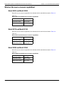
What are the source-measure capabilities?
Model 2601A and Model 2602A
Basic DC source-measure capabilities for the Models 2601A and 2602A are listed in Table 1-3.
Table 1-3
Model 2601A and 2602A source-measure capabilities
Function
Capabilities
Source ±DC voltage
Source ±DC current
Measure ±DC voltage
Measure ±DC current
1μV to 40.4V
1pA to 3.03A1
1μV to 40.8V
1pA to 3.06A1
1. 10A maximum available in pulse mode only.
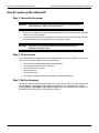
Model 2611A and Model 2612A
Basic DC source-measure capabilities for the Models 2611A and 2612A are listed in Table 1-4.
Table 1-4
Model 2611A and 2612A source-measure capabilities
Function
Capabilities
Source ±DC voltage
Source ±DC current
Measure ±DC voltage
Measure ±DC current
1μV to 202V
1pA to 1.515A1
1μV to 204V
1pA to 1.53A1
1. 10A maximum available in pulse mode only.
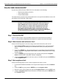
Model 2635A and Model 2636A
Basic DC source-measure capabilities for the Models 2635A and 2636A are listed in Table 1-5.
Table 1-5
Model 2635A and 2636A source-measure capabilities
Function
Capabilities
Source ±DC voltage
Source ±DC current
Measure ±DC voltage
Measure ±DC current
1μV to 202V
20fA to 1.515A
1μV to 204V
1fA to 1.53A
2600AS-900-01 Rev. B / September 2008
Return to Section Topics
1-9
Section 1: Front and Rear Panel Operation
Series 2600A System SourceMeter® Instruments User’s Manual
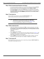
How do I power-up the instrument?
Step 1: Connect to line power
CAUTION
Operating the instrument on an incorrect line voltage may cause damage
to the instrument, possibly voiding the warranty.
1.
Before you plug the power cord into the Series 2600A, make sure that the front panel power
switch is in the off (O) position.
2.
Connect the female end of the supplied power cord to the AC receptacle on the rear panel.
Connect the other end of the power cord to a grounded AC outlet.
WARNING
Failure to use a grounded outlet may result in personal injury or
death due to electric shock.
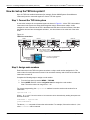
Step 2: Turn on power
Turn on the instrument by pressing the front panel power switch to the on (I) position. Assuming no
errors occur, the Series 2600A will power-up as follows:
1.
The OUTPUT indicators and display pixels flash briefly.
2.
•
•
•
•
The following items are shown in sequence:
The firmware revision number.
The line frequency.
The TSP-Link node.
The enabled command interface(s) and address (GPIB/LAN/RS-232).
Step 3: Set line frequency
The Series 2600A will operate at line frequencies of either 50Hz or 60Hz. For best measurement
noise performance, the unit should be configured to match the actual line frequency used by
selecting MENU > LINE-FREQ > 50Hz, 60Hz, or AUTO (when set to AUTO, the SourceMeter will
automatically detect the power line frequency at power-up).
1-10
Return to Section Topics
2600AS-900-01 Rev. B / September 2008
Series 2600A System SourceMeter® Instruments User’s Manual
Section 1: Front and Rear Panel Operation
How do I make measurements?
See the Series 2600A Reference Manual for more information on the following:
•
•
•
Basic source-measure procedure.
Ohms measurements.
Power measurements.
The measurement procedure below demonstrates how to set up the Series 2600A to source 10V
and measure current through a 10kΩ resistor.
WARNING
Hazardous voltages may be present on the output and guard
terminals. To prevent electrical shock that could cause injury or
death, NEVER make or break connections to the Series 2600A
while the output is on. Power off the equipment from the front
panel or disconnect the main power cord from the rear of the
SourceMeter before handling cables connected to the outputs.
Putting the equipment into standby does not guarantee the outputs
are not powered if a hardware or software fault occurs.
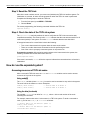
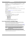
Step 1: Connect the DUT
Connect a 10kΩ resistor to the SourceMeter Channel A HI and LO terminals as shown in
Figure 1-4. See the Series 2600A Reference Manual for complete connection information.
Step 2: Select source and set source level
Perform the following steps to select the voltage source and set the source value to 10V:
1.
Press Channel A SRC to select the V-Source as indicated by the “V” units in the source
field on the display. The flashing cursor indicates which value is presently selected for
editing.
2.
Press the up RANGE key, and select the 20V source range (Model 2611A/2612A/2635A/
2636A) or 40V source range (Model 2601A/2602A). Use the lowest possible source range
for best accuracy.
3.
Use the CURSOR keys to move the cursor to the 10s digit, then press the navigation
wheel to enter the EDIT mode (EDIT indicator is displayed).
4.
Using the navigation wheel, set the source value to 10.0000V, then press the ENTER key
or the navigation wheel.
Step 3: Set compliance limit
Perform the following steps to set the current compliance limit value to 10mA:
1.
Put the Model 2602A/2612A/2636A in the single-channel display mode with the DISPLAY
key.
2.
Press the LIMIT key, then press the ENTER key or the navigation wheel.
3.
Move the cursor to the 10s digit, then press the navigation wheel to enter the EDIT mode.
4.
Using the navigation wheel, set the limit value to 10.000mA, then press the ENTER key or
the navigation wheel.
2600AS-900-01 Rev. B / September 2008
Return to Section Topics
1-11
Section 1: Front and Rear Panel Operation
Series 2600A System SourceMeter® Instruments User’s Manual
Step 4: Select measurement function and range
1.
Put the Model 2602A/2612A/2636A in the single-channel display mode with the DISPLAY
key, then select the current measurement function by pressing MEAS or MODE.
2.
Select the measurement range with the RANGE keys. For the purposes of this example,
press AUTO RANGE, and note that the AUTO indicator is displayed. The instrument will
automatically select the best range based on the measured value. You can also use manual
ranging by pressing the up or down RANGE key, but be sure to use the lowest possible
range for best accuracy.
Step 5: Turn output on
Turn the output on by pressing the appropriate OUTPUT ON/OFF key. The
ON/OFF indicator LED will turn on when the channel output is on.
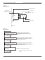
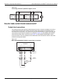
NOTE The Models 2611A, 2612A, 2635A, and 2636A are equipped with a
safety interlock circuit that prevents operation on the 200V range if
the circuit is not energized. This circuit is illustrated in Figure 1-5. See
to the Series 2600A Reference Manual for more information.
Step 6: Make measurements
1.
Observe the readings on the display (press TRIG if necessary to trigger the unit to begin
taking readings). For the single-channel display mode, the readings will appear on the top
line, while source and limit values are on the bottom line. For the 10kΩ resistor under test,
typical display values are:
1.00000mA
SrcA: +10.0000 V LimA:010.0000mA
2.
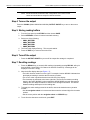
Use the DISPLAY key to cycle through the various display modes shown in Figure 1-6 (the
User State display messages are defined with specific display commands; see the Series
2600A Reference Manual for more information).
3.
Press the MEAS key several times to display measured voltage, resistance, and power.
Typical values for the 10kΩ resistor are: 10.0000V, 10.0000kΩ, and 10.0000mW.
Step 7: Turn output off
When finished making measurements, turn the output off by pressing the OUTPUT ON/OFF key.
The OUTPUT indicator light will turn off.
1-12
Return to Section Topics
2600AS-900-01 Rev. B / September 2008
Series 2600A System SourceMeter® Instruments User’s Manual
Section 1: Front and Rear Panel Operation
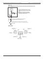
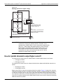
Figure 1-4
Model 2602A/2612A low-noise chassis ground banana jack and chassis screw
Series 2600A
Low-Noise
Chassis Ground
Banana Jack
Chassis
Screw 2
FVR 1
Signal
Ground
1) Frequency Variable Resistor (FVR) Isolates
the SMUs from high frequencies on the chassis.
For DC to 60Hz, the FVR is a virtual short (zero
ohms).
2) DO NOT use the Chassis Screw terminal to
make signal connections to external circuitry.
High frequency (>1MHz) on the chassis may
result in higher noise at the output.
Chassis
Signal
Ground
Chassis
Signal Ground is a local signal ground and defined as
the Low-Noise Chassis Ground Banana Jack.
Chassis is defined as the metal chassis of the Series 2600.
Chassis Screw terminal is connected to the metal chassis of the
Series 2600.
Model 2636A
2600AS-900-01 Rev. B / September 2008
Return to Section Topics
1-13
Section 1: Front and Rear Panel Operation
Series 2600A System SourceMeter® Instruments User’s Manual
Figure 1-5
Interlock circuit
Read by firmware
+220V supply
INTERLOCK pin
(on DIGITAL I/O connector)
-220V supply
Coil resistance
145WW +/- 10%
10kW
Chassis ground
To output stage
Rear panel
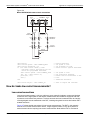
Figure 1-6
Display modes
1.00000mA
. V
SrcA:+10.0000V SrcB:+000.000mV
Press DISPLAY
key
1.00000mA
SrcA:+10.0000V LimA:10.0000mA
Press DISPLAY
SrcB:+000.000mV LimB:100.000mA
1-14
Source-Measure and Compliance Limit display for SMU B:
Top line displays the measure function (V, A, W or W)
Bottom line displays the source function (V or A) and level,
and the compliance limit (A or V).
key
User State
Press DISPLAY
Source-Measure and Compliance Limit display for SMU A:
Top line displays the measure function (V, A, W or W)
Bottom line displays the source function (V or A) and level,
and the compliance limit (A or V).
key
. V
Press DISPLAY
Source-Measure display for SMU A and SMU B:
Top line displays the measure function (V, A, W or W).
Bottom line displays the source function (V or A)
and level.
Display for user-defined messages and prompts.
key
Indicates that a measured reading has not been
triggered.
Return to Section Topics
2600AS-900-01 Rev. B / September 2008
Series 2600A System SourceMeter® Instruments User’s Manual
Section 1: Front and Rear Panel Operation
How do I use the reading buffer?
The instrument has two dedicated reading buffers per channel that can store over 60,000 readings
with the time stamps and source values options enabled. Disable the time stamps and source
values options to store over 140,000 readings.
The following example shows how to store 100 readings, source values, and timestamps in
Channel A, Buffer 1 and recall them from the front panel.
Step 1: Connecting the device under test (DUT)
Connect a 10kΩ resistor to the Channel A HI and LO terminals (see Figure 1-4).
Step 2: Set up source and measure functions
Using the procedure described in How do I make measurements?, set up source and measure
functions:
•
•
•
•
•
Source function: Volts.
Source range: 20 V (2611A/2612A/2635A/2636A) or 40V (2601A/2602A).
Source value: 10 V.
Measure function: Current.
Measure range: Auto.
Step 3: Configuring the reading buffer
Complete the following steps to configure reading buffers from the front panel:
1.
Press CONFIG > STORE and then choose one of the following:
• CHANA-BUFF
• CHANB-BUFF
2.
Select the DEST option and then choose one of the following:
• CHANX-BUFF1
• CHANX-BUFF2
• NONE
3.
Select BUFFER1 or BUFFER2.
4.
(Optional) To clear the buffer, turn the navigation wheel to select CLEAR > YES.
5.
Turn the navigation wheel to select ELEMENTS.
NOTE You must clear the reading buffer before you enable or disable the
source value or the time stamp options.
6.
(Optional) Push the navigation wheel to select TSTAMP, then select OFF or ON.
7.
8.
(Optional) Turn the navigation wheel to select SRC-VAL, then select OFF or ON.
Press the EXIT key to return to the main menu.
2600AS-900-01 Rev. B / September 2008
Return to Section Topics
1-15
Section 1: Front and Rear Panel Operation
Series 2600A System SourceMeter® Instruments User’s Manual
NOTE Model 2601A/2611A/2635A buffer configuration menu items are the
same as covered above except for channel selection.
Step 4: Turn on the output
Press the CHAN A (Model 2602A/2612A/2636A) OUTPUT ON/OFF key to turn on the source
output.
Step 5: Storing reading buffers
1.
From the front panel, press STORE and then choose SAVE.
2.
Select INTERNAL to save to internal nonvolatile memory.
3.
Select one of the following:
• SMUA_BUFFER1
• SMUA_BUFFER2
• SMUB_BUFFER1
• SMUB_BUFFER2
4. The front panel displays Saving... This may take awhile.
5. Press the EXIT key to return to the main menu.
Step 6: Turn off the output
•
Press the OUTPUT ON/OFF key to turn off the output after storage is completed.
Step 7: Recalling readings
1-16
1.
Press the RECALL key to access buffer readings (repeatedly pressing RECALL will cycle
through Buffer 1 then Buffer 2 for Channel A and then Channel B). A message will be
displayed if a buffer is empty.
2.
Note the buffer display data (see Figure 1-7):
• The buffer location number is on the right. For example, location #000001 indicates that
the displayed reading is stored at the first memory location.
• The source value is positioned at the lower left side of the display.
• The timestamp is positioned at the lower right side. The first source-measure reading
stored in the buffer (#000001) is time stamped at 00000.000000 seconds. Subsequent
readings are time stamped relative to when the time storage was started. The interval
between readings will depend on the reading rate.
3.
To display the other readings stored in the buffer, choose the desired memory location
number:
• Use the navigation wheel to increment and decrement the selected digit of the location
number.
• Set the cursor position with the navigation wheel or CURSOR keys.
4.
To exit from the data store recall mode, press EXIT.
Return to Section Topics
2600AS-900-01 Rev. B / September 2008
Series 2600A System SourceMeter® Instruments User’s Manual
Section 1: Front and Rear Panel Operation
Figure 1-7
Buffer display format
Reading
Source Value
(SrcA1=
Chan. A,
Buffer 1)
1.00000 mA
SrcA1:+10.0000 V
#0000001
@00000.000000s
Buffer Location Number
Timestamp (seconds)
Use Knob
1.00000 mA
SrcA1:+10.0000 V
#0000002
@00000.001000s
Note: Source values and timestamps
will be displayed only if enabled when
buffer is configured.
Use Knob
1.00000 mA
SrcA1:+10.0000 V
#0000003
@00000.002000s
Use Knob
1.00000 mA
SrcA1:+10.0000 V
#0000004
@00000.003000s
Saving the reading buffer to the USB flash drive
Complete the following steps to save the reading buffer data to a USB flash drive:
1.
Insert the USB flash drive into the USB port.
2.
Press STORE and use the navigation wheel to select SAVE > USB1.
3.
4.
5.
6.
7.
Select one of the following file formats:
• CSV
• XML
Use the navigation wheel to select the desired reading buffer.
Use the navigation wheel to change the file name.
Push the navigation wheel or the ENTER key to save the file.
Push EXIT to return to the main menu.
2600AS-900-01 Rev. B / September 2008
Return to Section Topics
1-17
Section 1: Front and Rear Panel Operation
Series 2600A System SourceMeter® Instruments User’s Manual
This page left blank intentionally.
1-18
Return to Section Topics
2600AS-900-01 Rev. B / September 2008
Section 2
Remote Operation
In this section:
Topic
Page
How do I use the remote interface?................................................. 2-2
Connect to the interface ............................................................... 2-2
Configure the interface ................................................................. 2-2
Working with the web interface........................................................ 2-8
How to use the Virtual Front Panel ............................................... 2-9
TSB embedded .................................................................................. 2-9
Issuing ICL commands ................................................................. 2-10
How do I use Test Script Builder?.....................................................
Run Test Script Builder .................................................................
Open and close an instrument resource .......................................
Save and clear console window ...................................................
Select command and language reference views ..........................
2-11
2-11
2-13
2-14
2-14
How do I use TSB to make measurements?...................................
Reset instrument...........................................................................
Select source function and set output value .................................
Set compliance value and measure range ...................................
Turn on output...............................................................................
Make a measurement ...................................................................
Print the result...............................................................................
Turn off output...............................................................................
2-14
2-15
2-15
2-16
2-16
2-16
2-16
2-16
How do I use other programs?
2-17
Using LabVIEW ............................................................................ 2-17
Using Visual Basic ........................................................................ 2-19
Section 2: Remote Operation
Series 2600A System SourceMeter® Instruments User’s Manual
How do I use the remote interface?
Connect to the interface
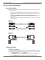
See Figure 1-2 for the locations of the GPIB (IEEE-488), RS-232, and LAN connectors, and make
connections as follows:
•
GPIB: Use a shielded IEEE-488 cable such as the Keithley Instruments Model 7007 to
connect the Series 2600A IEEE-488 connector to the GPIB connector on the host PC (see
Figure 2-1).
RS-232: Use a shielded 9-pin RS-232 cable like the Keithley Instruments Model 7009-5 to
connect the Series 2600A RS-232 connector to the serial port of the host PC
(see Figure 2-2).
LAN: Use the crossover cable supplied with the Series 2600A to connect directly to the host
PC’s network card.
•
•
Figure 2-1
GPIB cable
GPIB Cable
Side View
Connect one end of the cable to the host
PC and the other end to the SourceMeter.
Both cable connectors are identical.
Side View
Figure 2-2
RS-232 cable
Straight-through RS-232 Cable
Male DB-9 Connector
(connect to SourceMeter)
Female DB-9 Connector
(connect to PC)
Pin View
Pin View
Configure the interface
GPIB interface configuration
Set the primary address using the following procedure. The Series 2600A primary address must
be the same as that specified in your program, or the two devices will not be able to communicate.
2-2
1.
Press MENU > GPIB and then press the ENTER key.
2.
Select ADDRESS and then press the ENTER key. The Address screen is displayed.
3.
Turn the navigation wheel to the right or to the left to select the desired number.
Return to Section Topics
2600AS-900-01 Rev. B / September 2008
Series 2600A System SourceMeter® Instruments User’s Manual
4.
Section 2: Remote Operation
Push the navigation wheel and then turn the navigation wheel to choose an address.
NOTE The GPIB address can range from 1-30.
5.
6.
7.
Press the navigation wheel to set each digit.
Press the navigation wheel or the ENTER key to set the address.
Press EXIT to back out of the menu structure.
RS-232 interface configuration
Set RS-232 parameters as covered below. Before you can use the RS-232 interface to
communicate with the instrument, the serial port parameters for the host PC must match the serial
parameters set on the instrument.
1.
2.
3.
•
•
•
•
Press MENU to view the main menu.
Choose RS232, then press the ENTER key.
Choose the following options:
Select BAUD and then choose the desired option.
Choose BITS and then select the appropriate option.
Select PARITY and then choose the desired option.
Choose FLOW-CTRL and then select the appropriate option.
a. Use the navigation wheel to select ENABLE.
b. Select one of the following:
– ON
– OFF
6. Press EXIT to back out of the menu structure.
LAN interface configuration
Use the instructions below to configure the instrument's IP address based on the present IP
address of the host PC. Whenever there is an existing IP address configured for the network
interface card’s network settings, the IP address for the instruments on the Ethernet should also
be configured.
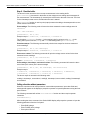
Step 1: Identify and record the PC's existing IP configuration Information
1.
Open the command prompt to see the existing IP configuration information:
• In Windows 2000/XP:
a. Click the Start button and select Run.
b. Type cmd in the Open field and click OK.
• In Windows Vista:
a. Click the Start button.
b. Select All Programs.
c. Select Accessories.
d. Select Command Prompt.
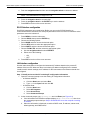
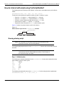
2.
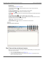
At the command prompt, type ipconfig/all and click Enter (see Figure 2-3).
a. If the information for the Ethernet adapter displays Media Disconnected, then close
the command prompt and skip to Step 2: Disable DHCP to use the computer's existing
IP address.
b. When the information is displayed, record the DHCP mode, IP address, subnet mask,
default gateway, and DNS servers.
2600AS-900-01 Rev. B / September 2008
Return to Section Topics
2-3
Section 2: Remote Operation
CAUTION
Series 2600A System SourceMeter® Instruments User’s Manual
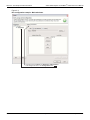
The ipconfig/all command displays the configuration of all network
connections. Be sure to record the information for the proper network card.
Figure 2-3
Computer configuration using the command prompt
3.
Verify DHCP or Static IP status.
• To determine the next step, check the DHCP Enabled setting in the IP configuration
screen or in the settings recorded earlier.
a. If DHCP Enabled = Yes, proceed to Step 2: Disable DHCP to use the computer's
existing IP address.
b. If DHCP Enabled = No, proceed to Step 3: Configure the Instrument's LAN settings.
NOTE When DHCP Enabled = Yes, the settings are assigned automatically
upon power up. However, if DHCP Enabled = No, the network will not
recognize the PC if the original settings are changed. If at any time
you are unsure how to proceed, contact your system administrator.
4.
2-4
To exit the IP configuration screen, type exit at the command prompt and press ENTER.
Return to Section Topics
2600AS-900-01 Rev. B / September 2008
Series 2600A System SourceMeter® Instruments User’s Manual
Section 2: Remote Operation
Step 2: Disable DHCP to use the computer's existing IP address
NOTE Do not change the IP address at any time without talking to your
system administrator first. Entering an incorrect IP address can
prevent your PC from connecting to your corporate network.
1.
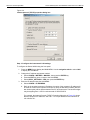
Open the Internet Protocol Properties dialog box
• In Windows 2000:
a. Click the Start button, select Settings, and then open the Control Panel.
b. Open Network and Dial-up Connections.
c. Right-click Local Area Connection and select Properties. The Local Area
Connection Properties dialog box is displayed.
d. Double-click Internet Protocol (TCP/IP) in the items list. The Internet Protocol
(TCP/IP) Properties dialog box is displayed (see Figure 2-4).
• In Windows XP:
a. Click the Start button and open the Control Panel.
b. Open Network Connections.
c. Right-click Local Area Connection and select Properties. The Local Area
Connection Properties dialog box is displayed.
d. Double-click Internet Protocol (TCP/IP) in the items list. The Internet Protocol
(TCP/IP) Properties dialog box is displayed (see Figure 2-4).
• In Windows Vista:
a. Click the Start button and open the Control Panel.
b. Open Network & Sharing Center.
c. In the list, click View Status next to Connection. The Wireless Network Connection
Status dialog box is displayed.
d. Click Properties. Windows displays a permissions message.
e. If you are logged in as administrator, click Continue. If you are not logged in as
administrator, enter the administrator's password to continue.
f. The Network Connection Properties dialog box is displayed.
g. Double-click Internet Protocol Version 6 (TCP/IPv6) in the items list. The Internet
Protocol Version 6 (TCP/IPv6) Properties dialog box is displayed (see Figure 2-4).
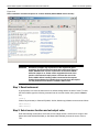
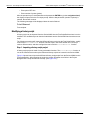
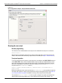
2.
Select Use the following IP address. The option for Use the following DNS server
addresses is automatically selected.
3.
Set the IP Address
a. Are the IP address and subnet mask fields populated?
• Yes: If populated, record the address, subnet mask, default gateway, and DNS
servers to use in Step 3: Configure the Instrument's LAN settings.
• No: If blank, enter the IP address 192.168.0.3 in the IP address field and
255.255.255.0 in the subnet mask field. These will be used to configure the
instrument’s LAN settings.
b. After recording or entering the IP address, click OK to close the Internet Protocol
(TCP/IP) Properties dialog box.
4.
Close the Network Connections window.
2600AS-900-01 Rev. B / September 2008
Return to Section Topics
2-5
Section 2: Remote Operation
Series 2600A System SourceMeter® Instruments User’s Manual
Figure 2-4
Internet protocol (TCP/IP) properties dialog box
Step 3: Configure the Instrument's LAN settings
To configure the Series 2600A using the front panel:
1.
Press the MENU key to display the MAIN MENU. Use the navigation wheel to select LAN
to display the LAN MENU.
2.
Change the IP address assignment method:
a. Select CONFIG > METHOD > MANUAL, then press the ENTER key.
b. Press the EXIT key once to return to the LAN MENU.
c. Select APPLY_SETTINGS > YES, then press the ENTER key.
3.
Enter the IP address using the LAN MENU:
a. Select CONFIG > IP-ADDRESS.
b. Refer to the recorded computer's IP address. A portion of the computer's IP address will
be used as a base for the instrument's unique ID. Only the last three numbers (after the
last decimal point) will be different between the PC and instrument. The last three digits
may be anything from 1-255 for a subnet mask of 255.255.255.0.
For example, the Internet Protocol (TCP/IP) Properties dialog box in Figure 2-3 shows
that the computer's IP address is 192.168.1.1. A unique address for the instrument is
192.168.001.101.
2-6
Return to Section Topics
2600AS-900-01 Rev. B / September 2008
Series 2600A System SourceMeter® Instruments User’s Manual
Section 2: Remote Operation
NOTE The instrument’s IP address can have leading zeros, but the
computer’s cannot.
c.
d.
e.
f.
4.
Use the navigation wheel to select and enter an appropriate IP address for the
instrument. Be sure to record the instrument’s IP address to use in Step 5: Access the
instrument's internal web page.
Push the ENTER key or navigation wheel to confirm the changes.
Press the EXIT key to return to the LAN MENU.
From the LAN MENU, select APPLY_SETTINGS > YES, then press the ENTER key.
Change the subnet mask from within the LAN MENU:
a. Select CONFIG > SUBNETMASK, then press the ENTER key. The SUBNETMASK
menu item is to the right of GATEWAY. Use the navigation wheel to scroll through the
options.
b. Modify the SUBNETMASK to match the PC settings recorded earlier or
255.255.255.000 if DHCP Enabled = YES.
c. Push the ENTER key or the navigation wheel when finished changing all the
characters.
d. Press the EXIT key to return to the LAN MENU.
e. From the LAN MENU, select APPLY_SETTINGS > YES, then press the ENTER key.
NOTE APPLY_SETTINGS must be used before changes to the IP address
or subnet mask are applied.
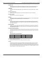
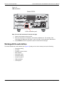
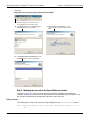
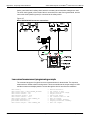
Step 4: Connect the crossover cable from the instrument to the PC network interface card
Connect the supplied crossover cable between the computer's NIC card and the Ethernet
connector on the instrument’s rear panel. There are multiple connectors on the Series 2600A rear
panel. Be sure to connect to the LAN connection port (see Figure 2-5).
NOTE Connect the crossover cable into the same PC Ethernet port that was
used during the configuration of the instrument. This will ensure that
the system is using the correct network card.
2600AS-900-01 Rev. B / September 2008
Return to Section Topics
2-7
Section 2: Remote Operation
Series 2600A System SourceMeter® Instruments User’s Manual
Figure 2-5
LAN connection
Model 2636A
WARNING:NO INTERNAL OPERATOR SERVICABLE PARTS,SERVICE BY QUALIFIED PERSONNEL ONLY.
SENSE
LO
LO
HI
CHANNEL A
SENSE
HI
GUARD
GUARD
SENSE
HI
CHANNEL B
HI
LO
SENSE
LO
LINE FUSE
SLOWBLOW
3.15A, 250V
RS-232
MADE IN
U.S.A.
!
LINE RATING
100-240VAC
50, 60Hz
240VA MAX.
DIGITAL I/O
IEEE-488
LAN
A LO
NO AUTO-MDIX
TSP-Link
R
CAUTION:FOR CONTINUED PROTECTION AGAINST FIRE HAZARD,REPLACE FUSE WITH SAME TYPE AND RATING.
LAN connection port
Step 5: Access the instrument's internal web page
1.
Open a web browser on the host PC.
2.
Enter the instrument’s IP address in the browser's address box. For example, if the
instrument's IP address is 192.168.0.3, enter 192.168.0.3 in the browser's address box.
3.
Press ENTER on the PC keyboard to open the instrument’s web page.
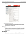
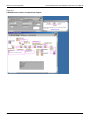
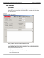
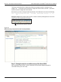
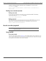
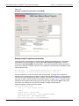
Working with the web interface
The Series 2600A has a web interface (see Figure 2-6) that you can use to remotely access the following:
•
•
•
•
•
•
•
•
•
2-8
Connection string
LXI class
Firmware version number
MAC address
Instrument model
Connection string
Virtual front panel
TSB embedded
TSP Express
Return to Section Topics
2600AS-900-01 Rev. B / September 2008
Series 2600A System SourceMeter® Instruments User’s Manual
Section 2: Remote Operation
Figure 2-6
Web interface
How to use the Virtual Front Panel
You can use the virtual front panel to access the features available from the front panel of the
Series 2600A. The same front panel features and functions are available from the Virtual Front
Panel with the exception of the POWER button.
TSP Express
TSP Express is a built-in utility that easily creates scripts for Series 2600A instruments (SMU). It
provides a menu of choices for building new test scripts as well as options for opening existing
projects and scripts. It also allows the user to view or change instrument configurations. TSP
Express may be launched using a web link from any Series 2600A instrument or by using a
shortcut on the host PC.
TSB embedded
TSB embedded is an alternative to a full version of Test Script Builder (TSB) Suite. The capabilities
of TSB embedded are very similar to TSB. TSB embedded includes a command line interface that
you can use to issue ICL commands, create, modify, and save test scripts to the instrument.
2600AS-900-01 Rev. B / September 2008
Return to Section Topics
2-9
Section 2: Remote Operation
Series 2600A System SourceMeter® Instruments User’s Manual
Issuing ICL commands
Use the console to send ICL commands to the instrument. The response from the instrument
appears in the Instrument output window.
Complete the following steps to send an ICL command:
1.
Type the command in the console and then click Enter.
2.
(Optional) Click Clear to clear the instrument output window.
How do I create a script with TSB embedded?
Complete the following steps to create a new script:
1.
Click the script editor window and then type the first line of your script. Click Enter to
advance to line 2.
2.
In the TSP Script line, type the name of the script and then click Save script.
The instrument validates the syntax and then saves the script to the nonvolatile memory.
How do I clear the script editor window in TSB embedded?
•
To remove the syntax from the script editor, click Clear.
How to run scripts with TSB embedded
•
To run a script, select the desired script from the User script window and then click Run.
How to stop scripts in TSB embedded
To stop a running script, click Abort script.
Deleting scripts
To delete a script from TSB embedded, select the desired script from the User script window and
then click Delete.
NOTE You cannot retrieve a deleted script.
Modifying scripts
Complete the following steps to modify a script:
1.
Select the desired script from the User script window and then modify the desired syntax in
the script editor.
2.
Click Save script to validate the syntax and save the script.
3.
•
•
When the message “Script clearing will be overwritten” is displayed, do one of the following:
To overwrite the script, click OK.
To save the script with a new name, click Cancel and then type the name of the script in the
name field.
Exporting Scripts
You can export a script to an external drive or store it as a backup on your PC.
1.
2-10
To export a script, click on the name of the script in the Users script window and then click
Export.
The Save dialogue box is displayed.
Return to Section Topics
2600AS-900-01 Rev. B / September 2008
Series 2600A System SourceMeter® Instruments User’s Manual
Section 2: Remote Operation
2.
Use the drop-down arrow to change folders, and navigate to the desired file.
3.
In the File name field, type the name of the file and then click Save.
How do I use Test Script Builder?
Step 1: Run Test Script Builder
Run the Test Script Builder program from the Keithley Instruments folder in the usual manner. The
initial startup screen shown in Figure 2-7 will be displayed. The main sections of the screen are
briefly described below:
Main Bar
The menu contain following options:
•
•
•
•
•
•
•
File: Use this option to control projects and files.
Edit: Performs a number of editing functions on script files.
Navigate: Navigates through projects.
Project: Opens, closes, and builds projects.
Run: Runs scripts.
Window: Selects which window to display.
Help: Provides access to online help files.
Project Navigator pane
The windowpane on the left side is where the Project Navigator is located. The navigator consists
of created project folders and the script files (.tsp) created for each project. Each project folder can
have one or more script files.
Script Development pane
The script chunk is written in the upper windowpane. It is in this area that scripts are written and/or
modified. Notice that there is a tab available for each opened script file. A script project is then
downloaded to the Series 2600A and run.
Series 2600A/Script Interaction pane
A number of tabs in the lower windowpane provide additional interaction between the Test Script
Builder, the Series 2600A and the opened script (the tabs displayed will depend on those selected
in the menu).
2600AS-900-01 Rev. B / September 2008
Return to Section Topics
2-11
Section 2: Remote Operation
Series 2600A System SourceMeter® Instruments User’s Manual
Figure 2-7
Test Script Builder initial startup screen
Menu Bar
Navigator
Pane
Script Development Pane
Control
Icons
SourceMeter/Script
Interaction Pane
Key tabs include:
Instrument Console: The Instrument Console is used to send commands to the connected
Series 2600A. Retrieved data (for example, readings) from commands and scripts appear in the
console.
Problems: When a script is saved, error checking is performed. If a script error is detected, an “X”
will appear in the script at or near the corrupt line of code. The Problems tab in the lower
windowpane will open automatically and provide a description of the error.
Tasks: When writing a script, a double dash (--) is used to designate that the text that follows is a
comment and not script code. When using the “--TODO” comment in a script, it will also appear in
the Tasks tab, where additional information can be added.
Command Help: Provides online help to the Instrument Command Library (ICL).
Language Help: Provides online help to the TSL programming language.
2-12
Return to Section Topics
2600AS-900-01 Rev. B / September 2008
Series 2600A System SourceMeter® Instruments User’s Manual
Section 2: Remote Operation
Control icons
Control icons (shown in Figure 2-8) include:
1. Open/Close Instrument
resource if open.
– Opens instrument resource if closed. Closes instrument
2. Clear Console Window
– Clears the instrument console window.
3. Abort Execution
4. Reset
output off.
– Halts execution of commands or scripts.
– Aborts whatever the unit is doing and resets everything to the default state with the
5. Send Software Trigger
– Sends a software trigger to take readings.
6. Delete a Script From NVRAM
– Opens a window that lists the scripts stored in the unit’s
nonvolatile memory, and allows you to remove scripts.
7. Menu
– Accesses the console menu.
8. Minimize/Maximize
– Minimizes or maximizes the console window.
Figure 2-8
Instrument console control icons
1
2
3
4
5
6
7
8
Step 2: Open and close an instrument resource
Before you can send commands or run scripts to control the Series 2600A, you must first open the
instrument resource as follows:
1.
Click on the Open Instrument icon (see Figure 2-8).
2.
Choose the desired instrument from the dialog box (see Figure 2-9) drop-down menu to
select a communications resource:
2600AS-900-01 Rev. B / September 2008
Return to Section Topics
2-13
Section 2: Remote Operation
•
•
Series 2600A System SourceMeter® Instruments User’s Manual
GPIB: At the factory, the GPIB address for the Series 2600A is set to 26. If using the
GPIB interface board 0 and address 26, the resource setting should be
GPIB0::26::INSTR. Resource settings for other GPIB board numbers and primary
addresses are available from the dialog box.
RS-232: Typically, the COM1 serial port of the PC is used for RS-232 communications.
For COM1, use the ASRL1::INSTR resource setting. Resource settings for other COM
ports are available from the dialog box.
3.
If you select the Simulate option, the Instrument Console will become active even though
there will be no actual communication with the Series 2600A. You can simulate running a
script or sending a command, but the Series 2600A will not respond.
4.
To close the resource, click on the Instrument icon again. The resource will close, and the
console window will become inactive.
Figure 2-9
Select Instrument Resource dialog box
Step 3: Save and clear console window
You can save and clear the console window as follows:
•
•
Save console: Click on the Menu arrow (see Figure 2-7), choose Save Console, then
choose the folder and filename desired.
Clear console: Click on the Clear Console icon (see Figure 2-7) to clear the console
window.
Step 4: Select command and language reference views
You can access online help for the ICL (Instrument Control Library) and TSL (Test Script
Language) as follows:
•
•
ICL: Click on the Command Help tab at the top, then click the Maximize icon. You can then
quickly get information on all commands in the library.
TSL: Click on the Language Help tab at the top, then click the Maximize icon to quickly
access details on the script language.
How do I use TSB to make measurements?
The following procedure uses the TSB Instrument Console to send commands to source voltage
and measure current on Channel A using a 10kΩ resistor as the DUT. The complete command
sequence as it would appear in the console window is shown in Figure 2-10 along with instrument
responses.
The procedure assumes the DUT (10kΩ resistor) is already connected to the Series 2600A (see
Figure 1-4), and that the instrument resource has already been opened (see Open and close an
instrument resource).
2-14
Return to Section Topics
2600AS-900-01 Rev. B / September 2008
Series 2600A System SourceMeter® Instruments User’s Manual
Section 2: Remote Operation
Figure 2-10
Source-measure command sequence in console window (2601A/2602A version shown)
Reset SourceMeter
Select volts function
Set source range to 40V
Set source level to 10V
Set current limit to 10mA
Set measure range to 10mA
Turn on output
Take current reading
Print current reading
Instrument response
Print resistance reading
Instrument response
Print power reading
Instrument response
Turn off output
WARNING
Hazardous voltages may be present on the output and guard
terminals. To prevent electrical shock that could cause injury or
death, NEVER make or break connections to the Series 2600A
while the output is on. Power off the equipment from the front
panel or disconnect the main power cord from the rear of the
Series 2600A before handling cables connected to the outputs.
Putting the equipment into standby does not guarantee the outputs
are not powered if a hardware or software fault occurs.
Step 1: Reset instrument
A good practice is to reset the instrument to its default settings before the start of a test. To reset
the Series 2600A, type the following command into the console window, then press the Return
key:
reset()
Channel A (all models) or Channel B (2602A, 2612A, 2636A only) defaults can be reset as follows:
smua.reset()
smub.reset()
Step 2: Select source function and set output value
Enter the following commands to select the source voltage function, set the source range to 20V
(Model 2611A/2612A/2635A/2636A) or 40V Model 2601A/2602A), and set the source value to
10V:
2600AS-900-01 Rev. B / September 2008
Return to Section Topics
2-15
Section 2: Remote Operation
smua.source.func =
smua.source.rangev
smua.source.rangev
smua.source.levelv
Series 2600A System SourceMeter® Instruments User’s Manual
smua.OUTPUT_DCVOLTS
= 40
(Use for Model 2601A/2602A)
= 20
(Use for Model 2611A/2612A/2635A/2636A)
= 10
Step 3: Set compliance value and measure range
Enter the following commands to set the compliance limit and measure range to 10mA:
smua.source.limiti = 10e-3
smua.measure.rangei = 10e-3
Step 4: Turn on output
Send the following command to turn on the output:
smua.source.output = smua.OUTPUT_ON
Step 5: Make a measurement
Enter the following command to take a current measurement:
reading = smua.measure.i()
Step 6: Print the result
Print the result in the console window with the following command:
print(reading)
Note that the reading response will appear in the console window (see Figure 2-10).
Alternatively, you can also take and print readings by including the appropriate measure
command as the argument in the print command. For example, the following commands will
take and print ohms and power readings respectively:
print(smua.measure.r())
print(smua.measure.p())
Again, readings will be displayed in the console window.
Step 7: Turn off output
Send the following command to turn off the output when measurements are complete:
smua.source.output = smua.OUTPUT_OFF
2-16
Return to Section Topics
2600AS-900-01 Rev. B / September 2008
Series 2600A System SourceMeter® Instruments User’s Manual
Section 2: Remote Operation
How do I use other programs?
Reference
See the LabVIEW and Visual Basic documentation for details on using those
programs.
Basic source-measure examples using LabVIEW and Visual Basic are shown below. See also
Section 3 for more examples to load and run scripts.
Using LabVIEW
The source-measure example using LabVIEW is shown in Figure 2-11. The test steps are:
1.
Reset instrument.
2.
Select source voltage function.
3.
Set source output voltage.
4.
Turn on output.
5.
Take current measurement.
6.
Reset instrument.
The command sequence for this source-measure example is shown below:
localnode.prompts = 0
-- Disable prompts.
reset()
-- Reset Series 2600A.
smua.source.func = smua.OUTPUT_DCVOLTS -- Select voltage source
-- function.
smua.source.levelv = volts
-- Set voltage source level.
smua.source.output = smua.OUTPUT_ON
-- Turn on source output.
print(smua.measure.i())
-- Take and return current
-- reading.
reset()
-- Reset Series 2600A.
The commands above are sent out in LabVIEW using either GPIB or VIS VIs. Refer to the
LabVIEW documentation for information on using VIs.
2600AS-900-01 Rev. B / September 2008
Return to Section Topics
2-17
Section 2: Remote Operation
Series 2600A System SourceMeter® Instruments User’s Manual
Figure 2-11
LabVIEW source-measure example block diagram
2-18
Return to Section Topics
2600AS-900-01 Rev. B / September 2008
Series 2600A System SourceMeter® Instruments User’s Manual
Section 2: Remote Operation
Using Visual Basic
User interface
The GUI (graphical user interface) shown in Figure 2-12 was created to demonstrate how to
control a Keithley Instruments Series 2600A SourceMeter® instrument using Visual Basic 6.0.
Source code for this example program can be downloaded from the Keithley Instruments internet
site, www.keithley.com.
Figure 2-12
Visual Basic example user interface
Using the Series 2600A as a traditional GPIB instrument
The following pseudocode describes how the Series 2600A will be configured and controlled to
source voltage and measure current for this example. Some of the settings are default values
restored by resetting the instrument, but they are included to show a typical setup and measure
sequence that might be used for such a test.
1.
Reset Series 2600A to default settings.
2.
Set display to show SMU A source and limit settings.
3.
Set display to show current measurement.
4.
Set source function to DCV.
2600AS-900-01 Rev. B / September 2008
Return to Section Topics
2-19
Section 2: Remote Operation
Series 2600A System SourceMeter® Instruments User’s Manual
5.
Enable source autorange.
6.
Set source level to 5V.
7.
Set current compliance to 100mA.
8.
Set current measurement range to 100mA.
9.
Set integration time to 1PLC.
10.
Turn on SMU A output.
11.
Measure the current and put reading in instrument output queue. This step is similar to
using a SCPI “READ?” query to take a single reading.
12.
Turn off SMU A output.
Command sequence
The commands that implement the pseudocode are listed below. The syntax for the “send” and
“enter” commands is designed for a Keithley Instruments GPIB card. To use a Keithley Instruments
GPIB card in Visual Basic, you must include the “ieeevb.bas” module in your project. This module
is included on the CD that comes with your GPIB card.
When you click the Run with GPIB button on the GUI, the commands are sent to the Series
2600A and executed. The single reading returned by these commands is displayed in the Data
text box as shown in Figure 2-13.
NOTE Addr% is the GPIB address of the instrument and is assigned the
value of 26.
Call send(Addr%, "localnode.prompts = 0", intStatus)
Call send(Addr%, "reset()", intStatus)
Call send(Addr%, "display.screen = display.SMUA", intStatus)
Call send(Addr%, "display.smua.measure.func = display.MEASURE_DCAMPS",
intStatus)
Call send(Addr%, "smua.source.func = smua.OUTPUT_DCVOLTS", intStatus)
Call send(Addr%, "smua.source.autorangev = smua.AUTORANGE_ON", intStatus)
Call send(Addr%, "smua.source.levelv = 5", intStatus)
Call send(Addr%, "smua.source.limiti = 0.1", intStatus)
Call send(Addr%, "smua.measure.rangei = 0.1", intStatus)
Call send(Addr%, "smua.measure.nplc = 1", intStatus)
Call send(Addr%, "smua.source.output = smua.OUTPUT_ON", intStatus)
Call send(Addr%, "print(smua.measure.i())", intStatus)
Call send(Addr%, "smua.source.output = smua.OUTPUT_OFF", intStatus)
Call enter(strBuffer, 256, intNbytes, Addr%, intStatus)
txtData.Text = strBuffer
Using VISA
Clicking on the “Run with VISA” button will send the same commands to the Series 2600A using
National Instruments® (NI) VISA. The VISA resource is for an instrument at address 26 connected
to GPIB interface #1. Once again, a Keithley Instruments GPIB card was used for this example.
However, VISA allows the same code to be used with GPIB cards made by other manufacturers,
or with altogether different interfaces such as the RS-232 or the Ethernet.
2-20
Return to Section Topics
2600AS-900-01 Rev. B / September 2008
Series 2600A System SourceMeter® Instruments User’s Manual
Section 2: Remote Operation
Figure 2-13
Example program test results
2600AS-900-01 Rev. B / September 2008
Return to Section Topics
2-21
Section 2: Remote Operation
Series 2600A System SourceMeter® Instruments User’s Manual
This page left blank intentionally.
2-22
Return to Section Topics
2600AS-900-01 Rev. B / September 2008
Section 3
Test Script Processor Interaction
In this section:
Topic
Page
What is a script? ............................................................................... 3-2
Factory scripts .............................................................................. 3-2
User scripts................................................................................... 3-2
How do I run a script from the front panel? ................................... 3-2
How do I interact with scripts using Test Script Builder?.............
Running a factory script ................................................................
Modifying a factory script ..............................................................
Running the user script.................................................................
Deleting a user script and user tests ............................................
3-4
3-4
3-6
3-11
3-12
How do I use other programs? ........................................................ 3-12
Using LabVIEW ............................................................................ 3-12
Using Visual Basic ........................................................................ 3-14
Series 2600A System SourceMeter® Instruments User’s Manual
Section 3: Test Script Processor Interaction
What is a script?
A script is a collection of instrument control commands and programming statements to perform
one or more operations or tasks. A script is stored in a Series 2600A instrument and is run by its
Test Script Processor (TSP).
Factory scripts
The Series 2600A is shipped from the factory with at least one factory script stored in its
nonvolatile memory. Each factory script is made up of a series of functions to perform specific
tests. A factory script function can be called (run) from the front panel or called using remote
programming. A factory script cannot be deleted from nonvolatile memory.
User scripts
A user script is a script created by a user using the Test Script Builder or an external program. The
user script is loaded in the Series 2600A and stored in volatile or nonvolatile memory. If stored in
nonvolatile memory, the script will not be lost when the instrument is turned off.
Keithley Instruments will be posting approved user scripts donated by registered users on its web
site. You will be able to download these user scripts into your Series 2600A. Visit
www.keithley.com for details.
How do I run a script from the front panel?
Choose to run scripts from the following options:
• Factory
• Users
• Scripts
All factory script functions are interactive if accessed from the front panel. This means you must
manually enter the parameters.
A user script can be non-interactive or interactive. A non-interactive script does not require user
input.
NOTE If the Series 2600A is in remote operation, press the LOCAL key to
return control to the front panel.
To run a script from the front panel:
In order to run a script from the front panel, an entry for the script needs to be added to the user
menu for the LOAD key. The following commands are used to enter or delete a name into the user
menu:
display.loadmenu.add(displayname, script)
display.loadmenu.delete(displayname)
Where: displayname is the name to be added to (or deleted from) the user menu and script is a
string with the code that will be associated with the displayname.
It does not matter what order the items are added to the user menu. Menu items will be displayed
in alphabetical order when the menu is selected.
Example:
3-2
Return to Section Topics
2600AS-900-01 Rev. B / September 2008
Series 2600A System SourceMeter® Instruments User’s Manual
Section 3: Test Script Processor Interaction
Assume a user script named “Test9” has been loaded into the run-time environment. Add the
name (“Test9”) to the User menu for the script as follows:
display.loadmenu.add(“Test9”, “Test9()”)
After adding a name to the User menu, the script can then be run from the front panel as follows:
1.
Press the LOAD key to display the LOAD TEST menu.
2.
Position the blinking cursor on the FACTORY or USER menu item and press the ENTER
key or the navigation wheel. NOTE: The Series 2600A is shipped with no user scripts
loaded.
3.
Position the blinking cursor on the test to be run, and then press the ENTER key.
4.
Press the RUN key to start the test.
5.
Enter required test parameters using the front panel controls.
How do I save scripts to the USB flash drive?
The Series 2600A supports the standard USB 2.0 device interface. You can save data to the USB
flash drive from the front panel while executing a script or from a remote interface.
Connecting the USB flash drive
To connect the USB flash drive, insert the USB flash drive into the USB connector, located on the
front panel of the instrument.
Saving scripts to the USB flash drive
Complete the following steps to save a script to the USB flash drive from the front panel:
1.
Press MENU > SCRIPT and then select SAVE.
2.
•
•
Do one of the following:
Turn the navigation wheel to the left or to the right to select the script to be saved.
Push the navigation wheel or press the ENTER key to select the desired script from the
list.
3.
Press USB1.
4.
(Optional) Use the navigation wheel to change the last three characters of the file name.
5.
Press the ENTER key to save the script to the USB flash drive.
NOTE The message “Overwrite” is displayed if the file already exists.
2600AS-900-01 Rev. B / September 2008
Return to Section Topics
3-3
Series 2600A System SourceMeter® Instruments User’s Manual
Section 3: Test Script Processor Interaction
How do I interact with scripts using Test Script Builder?
The following function for factory script “KIPulse” is stored in the nonvolatile memory of the Series
2600A:
PulseVMeasureI(smu, bias, level, ton, toff, points)
The above function performs a specified number of pulse V, measure I cycles:
• Sets the smu to output bias volts and dwell for ton seconds.
• Sets the smu to output level volts and dwell for ton seconds.
• Performs current measurement with the source at level volts.
• Sets the smu to output bias volts for toff seconds.
• Repeats the above sequence for points pulse-measure cycles.
Figure 3-1 shows one pulse-measure cycle for the function.
Figure 3-1
Pulse-measure cycle for the PulseVMeasureI function
level
bias
bias
ton
Current measurement
ton
toff
Running a factory script
NOTE All commands to run a factory script are to be executed from the
Instrument Console of the Test Script Builder.
The following steps explain how to run the PulseVMeasureI function and read the data stored in
the buffer.
NOTE The “KIPulse” factory script is an autorun script. The script runs
automatically when the Series 2600A is turned on. The functions of
the script are ready to be called.
Step 1: Call the function
The following are example parameters for the PulseVMeasureI function which will perform three
pulse voltage, measure current cycles:
smu
SMU A
bias
-1V
level
1V
ton
1ms
toff
2ms
points
3
The following command will execute the PulseVMeasureI function using the above parameters:
PulseVMeasureI(smua, -1, 1, 1E-3, 2E-3, 3)
3-4
Return to Section Topics
2600AS-900-01 Rev. B / September 2008
Series 2600A System SourceMeter® Instruments User’s Manual
Section 3: Test Script Processor Interaction
Step 2: Read the buffer
The above function stores the three current measurements in the reading buffer
(smua.nvbuffer1). Also stored in the buffer are the voltage source settings and timestamps for
the measurements. The timestamps (in seconds) are referenced to the start of the test. The timer
for the timestamps starts at zero seconds when the test is started.
The printbuffer function is used to print (output) measured readings, timestamps and/or source
values stored in the buffers.
Print readings: The following code will return the three measured current readings stored in
nvbuffer1:
rb1 = smua.nvbuffer1
printbuffer(1, rb1.n, rb1)
Example output: 1.234567e-03, 2.362360e-03, 2.362368e-03
For the above printbuffer function, 1 is the starting index for values to print, rb1.n is the
ending index (for this function, n = 3), and rb1 is the reading buffer (smua.nvbuffer1).
Print time stamps: The following command will print the time stamps for the three measured
current readings:
printbuffer(1, rb1.n, rb1.timestamps)
Example output: 5.555555e-02, 8.888888e-02, 1.111111e-01
Print source values: The following command will print the voltage source values for the three
measured current readings:
printbuffer(1, rb1.n, rb1.sourcevalues)
Output: 1.000000e+00, 1.000000e+00, 1.000000e+00
Print readings, time stamps, and source values: The following command will return the three
sets of data (nine values) in the same message:
printbuffer(1, rb1.n, rb1, rb1.timestamps, rb1.sourcevalues)
Example output:
1.234567e-03, 5.555555e-02, 1.000000e+00, 2.362360e-03, 8.888888e-02,
1.000000e+00, 2.362368e-03, 1.111111e-01, 1.000000e+00
The above output is returned in the following order:
reading1, timestamp1, sourcevalue1, reading2, timestamp2, sourcevalue2, reading3, timestamp3,
sourcevalue3
Calling a function without parameters
When the command to call a script function is sent without parameters, input value fields and
messages will appear on the display to prompt the operator to input the parameters using the front
panel controls.
The following command will call the SourceVMeasureI function and then require operator
interaction:
PulseVMeasureI()
After sending the above command, the Series 2600A display will prompt the operator to input the
following parameters from the front panel:
•
•
•
Enter BIAS voltage.
Enter PULSE (level) voltage.
Enter pulse ON time.
2600AS-900-01 Rev. B / September 2008
Return to Section Topics
3-5
Series 2600A System SourceMeter® Instruments User’s Manual
Section 3: Test Script Processor Interaction
•
•
Enter pulse OFF time.
Enter number of pulses (points).
After the operator keys in each parameter and presses the ENTER key (or the navigation wheel),
the display will proceed to the next input prompt. After the last parameter (number of pulses) is
entered, the test will continue.
The following message will be displayed when the test is finished:
PulseVMeasureI
Test complete.
Modifying a factory script
A factory script can be imported from the Series 2600A into the Test Script Builder where it can be
modified. The modified script can then be loaded back into the Series 2600A and saved as a user
script.
The following procedure will import the KIGeneral factory script into the Test Script Builder, modify
code for the SourceVMeasureI function, load the script in the Series 2600A as a user script
under a different name, and then configure the test to call the SourceVMeasureI function.
Step 1: Importing a factory script project
A factory script project is made of many executable functions. The SourceVMeasureI function is
one of the functions that make up the KIGeneral factory script that is stored in the Series 2600A.
Figure 3-2 shows how to import the KIGeneral factory script project from the Series 2600A into the
Test Script Builder. After importing the script, the project will appear as a folder in the Project
Navigator with a script file named “main.tsp” (see Figure 3-3).
3-6
Return to Section Topics
2600AS-900-01 Rev. B / September 2008
Series 2600A System SourceMeter® Instruments User’s Manual
Section 3: Test Script Processor Interaction
Figure 3-2
Importing a factory script project from the Series 2600A
A) Click File to display the drop-down file menu
and click Import to open the Import wizard.
B) In the Import Select box, click Existing Project
From Instrument and then click Next.
C) Import Open/Close instrument box With
communications to the Series 2600 open, click
Next.
If communications are not open, use the
drop-down menu to select a resource and
click Open
D) In the Import Project From Instrument box, click
the KIGeneral project, and then cllick Finish.
KIGeneral
KIGeneral
Step 2: Modifying the test code for the SourceVMeasureI function
As shown in Figure 3-3, the test code for the script functions is contained in the tab for the
“main.tsp” script file. The test code for all of the functions of the KIGeneral factory script are in this
tab. Use the scroll buttons on the right side of the tab to view more code.
Editing example
The following line of code in the “main.tsp” script file applies to the SourceVMeasureI function:
bias = display.prompt("+00.000", " Seconds", "Enter BIAS Voltage.", 0, -40,
40)
2600AS-900-01 Rev. B / September 2008
Return to Section Topics
3-7
Series 2600A System SourceMeter® Instruments User’s Manual
Section 3: Test Script Processor Interaction
The above command defines a display input field and message prompt for entering the bias
voltage. The -40 parameter sets the minimum voltage that can be entered, and the 40 parameter
sets the maximum voltage that can be entered.
Now assume you wish to change the bias input limits to ±10V. Edit the line of code to the following:
bias = display.prompt("+00.000", " Seconds", "Enter BIAS Voltage.", 0, -10,
10)
Saving the script: After modifying the script file, it must be saved by clicking the save icon on the
toolbar of the Test Script Builder as follows:
Click to save the main.tsp script file
Figure 3-3
KIGeneral project imported into the Test Script Builder
Test Code
Project Navigator
Step 3: Storing the script in nonvolatile memory of the Series 2600A
After modifying a factory script, it can be loaded back into the Series 2600A and saved in
nonvolatile memory as a user script.
3-8
Return to Section Topics
2600AS-900-01 Rev. B / September 2008
Series 2600A System SourceMeter® Instruments User’s Manual
Section 3: Test Script Processor Interaction
1. The Run configuration box is used to launch (load) a user script into the Series 2600A and
save it in nonvolatile memory. As shown below, open the Run box and then click Run in the
drop-down menu:
Click Run and then click Run
in the drop-down menu.
NOTE Figure 3-4 and Figure 3-5 show how the Run box will look after the
launch is configured.
2. In the Configurations area of the Run box, select the KIGeneral script. The launch
configuration tabs for that script will appear in the Run box.
3. Presently, the name of the script is KIGeneral. You should change the name so the script is not
confused with the factory script of the same name that is stored in the Series 2600A. For
example, change the script Name to “KIGeneralUser” and click the Apply button.
4. As shown in Figure 3-4, the main.tsp file must be in the Load Order area of the Run box. If it is
in the Available Project Files area, double-click main.tsp to move the file over.
5. Click the Script Attributes tab to display the load and store options and select the LoadOnly
run action and nonvolatile storage as shown in Figure 3-5.
6. Click the Apply button to set the run configuration.
7. Click the RUN key to load the user script into nonvolatile memory of the Series 2600A.
NOTE There is a small bar graph at the bottom-right of the Test Script
Builder that will appear while a script is loading. The bar graph will
continuously sequence through its segments while the script is
loading.
2600AS-900-01 Rev. B / September 2008
Return to Section Topics
3-9
Series 2600A System SourceMeter® Instruments User’s Manual
Section 3: Test Script Processor Interaction
Figure 3-4
Run configuration example - Main tab shown
Changing the script Name from KIGeneral to KIGeneralUser
also changes the name in the Configurations area.
3-10
Return to Section Topics
2600AS-900-01 Rev. B / September 2008
Series 2600A System SourceMeter® Instruments User’s Manual
Section 3: Test Script Processor Interaction
Figure 3-5
Run configuration example - Script Attributes tab shown
Running the user script
Remote programming
The functions for the KIGeneralUser user script can be called after the script is run as follows:
KIGeneralUser()
After the above command is executed, any of the functions that make up the user script can be
called in the same manner that factory script functions are called (see Step 1: Call the function).
Front panel operation
To run the script from the front panel, a test name has to be added to the USER TESTS submenu
of the LOAD TEST menu. Since the KIGeneralUser script is made up of eight functions, a front
panel user test must run the script and also call a function. The following command will add the
test name “PulseVMeasI” to the menu. It will also configure the test to run the KIGeneralUser
script and call the PulseVMeasureI function:
display.loadmenu.add("PulseVMeasI", "KIGeneralUser() PulseVMeasureI()",
display.SAVE)
Because no parameters are used in the function (PulseVMeasureI()), the test will be interactive
and require the operator to input the test parameters using the front panel controls. See How do I
run a script from the front panel? for details on running a user script from the front panel.
The command display.loadmenu.add can be used to configure front panel user tests for the
other functions of the script. Make sure to use a different menu name for each function. For
2600AS-900-01 Rev. B / September 2008
Return to Section Topics
3-11
Series 2600A System SourceMeter® Instruments User’s Manual
Section 3: Test Script Processor Interaction
example, the following command will add the name “PulseIMeasV” for a test to call the
PulseIMeasureV function.
display.loadmenu.add("PulseIMeasV", "KIGeneralUser() PulseIMeasureV()",
display.SAVE)
Deleting a user script and user tests
Deleting a user script
A user script can be deleted from nonvolatile memory of the Series 2600A. The following
command will delete the KIGeneralUser user script:
script.delete("KIGeneralUser")
Deleting a user test
After deleting a script, you should also delete the test from the USER TESTS menu since it no
longer exists. The following command deletes the “PulseVMeasI” test from the menu:
display.loadmenu.delete("PulseVMeasI")
How do I use other programs?
NOTE See the LabVIEW and Visual Basic documentation for details on
using those programs.
Using LabVIEW
Source step example
The source step example is shown in Figure 3-6. The example steps the source voltage from 1V to
10V in 1V steps, measures the current at each step, and stores the result in a table. Once all steps
are completed, the stored table current values are printed.
3-12
Return to Section Topics
2600AS-900-01 Rev. B / September 2008
Series 2600A System SourceMeter® Instruments User’s Manual
Section 3: Test Script Processor Interaction
The Series 2600A command sequence:
localnode.prompts = 0
data_table = {}
reset()
smua.source.output = 1
for i=1,10 do
smua.source.levelv = i
mi = smua.measure.i()
table.insert(data_table,mi)
end
smua.source.output = 0
print(table.concat(data_table,’,’))
reset()
-------------
Disable prompts.
Clear table.
Reset Series 2600A.
Turn on source output.
Loop for 10 steps.
Set source level.
Take a current measurement.
Store measurement in table.
End of loop.
Turn off output.
Print table of current values.
Reset instrument.
Figure 3-6
LabVIEW source step example
2600AS-900-01 Rev. B / September 2008
Return to Section Topics
3-13
Section 3: Test Script Processor Interaction
Series 2600A System SourceMeter® Instruments User’s Manual
Using Visual Basic
NOTE The form file (UserManualExample.frm) can be opened using any
text editor to view the code executed by the various command
buttons.
The following examples look at how you can download and run Model 2600A Series scripts using
Visual Basic. Two scripts were created for these examples. Both scripts are based on the
pseudocode and instrument commands presented in Section 2 on using the Series 2600A as a
traditional GPIB instrument while they perform multiple measurements. Source code for this
example program can be downloaded from the Keithley Instruments internet site,
www.keithley.com.
Example script 1: script that does not use functions
The following script is in the file named “MeasCurrScript.tsp.” Note that the actual script contains
additional comments, which have not been included here. Comments are identified by double
dashes (--).
reset()
display.screen = display.SMUA
display.smua.measure.func = display.MEASURE_DCAMPS
smua.source.func = smua.OUTPUT_DCVOLTS
smua.source.autorangev = smua.AUTORANGE_ON
smua.source.levelv = 5
smua.source.limiti = 0.1
smua.measure.rangei = 0.1
smua.measure.nplc = 1
smua.source.output = smua.OUTPUT_ON
ntimes = 10
for i = 1, ntimes do
-- Perform following command(s) ntimes.
print(smua.measure.i())
-- Measure current and put reading in out-
put queue.
end --for
smua.source.output = smua.OUTPUT_OFF
The primary code that reads the file and downloads the script to the Series 2600A is listed below.
This code is executed when you select the Load “Non-Function” Script option, and then click
the Load Script (GPIB) command button. Although not required, TSP prompts are enabled for
this example because they provide useful test script processor status information when loading
and running scripts. See the Series 2600A Reference Manual for more information about using
prompts. As the script is being downloaded, it is displayed in the Script text box of the GUI
(Graphical User Interface), as shown in Figure 3-7.
3-14
Return to Section Topics
2600AS-900-01 Rev. B / September 2008
Series 2600A System SourceMeter® Instruments User’s Manual
Call send(Addr%, "localnode.showerrors =
0", intStatus)
Call send(Addr%, "localnode.prompts =
1", intStatus)
strReturnMessage = udfGetTspResponse()
Open App.Path & "\" &
"MeasCurrScript.tsp" For Input As #1
Call send(Addr%, "loadscript
MeasCurrScript", intStatus)
strReturnMessage = udfGetTspResponse()
Section 3: Test Script Processor Interaction
‘Disable automatic display of errors
‘leave error messages in queue and
‘enable Error Prompt. The "localnode" is
‘unit being communicated with via GPIB
‘or RS-232.
‘Turn on prompts; need to start
‘handling the prompts as soon as this
‘command is sent.
‘Open the script file for sequential
‘input.
‘"loadscript" identifies the beginning
‘of the script. "MeasCurrScript" is the
‘name assigned to the script.
‘Read the file.
Do While Not EOF(1)
‘Loop until the end of the script file.
Line Input #1, strScriptline
‘Read a line from the script file.
Call send(Addr%, strScriptline, intStatus) ‘Send script line to Series 2600A.
strReturnMessage = udfGetTspResponse()
strReturnMessage = Left(strReturnMessage,
4)
Select Case strReturnMessage
Case ">>>>"
Case "TSP>"
‘Ready prompt.
‘TSP received script successfully;
‘ready for next command.
Exit Do
Case "TSP?"
‘Error prompt.
‘Error occurred; handle as desired.
‘Use "errorqueue" commands to read
‘and clear errors.
‘No prompt received.
‘Response other than shell prompt was
‘received; handle as desired.
Case Else
End Select
Loop
Close #1
Call send(Addr%, "endscript", intStatus)
strReturnMessage = udfGetTspResponse()
Call send(Addr%, "localnode.prompts =
0", intStatus)
2600AS-900-01 Rev. B / September 2008
‘Continuation prompt.
‘TSP received script line successfully;
‘waiting for next line.
‘Close the script file.
‘Tell TSP complete script has been
‘downloaded.
‘Disable prompts.
Return to Section Topics
3-15
Section 3: Test Script Processor Interaction
Series 2600A System SourceMeter® Instruments User’s Manual
Figure 3-7
GUI after loading the non-function script (GPIB)
The primary code that runs the script and retrieves the measurement results is listed below. This
code is executed when you click the Run Script (GPIB) command button. When you run this
script it will perform ten measurements and send the readings to the PC. The results are displayed
in the Data text box of the GUI as shown in Figure 3-8. TSP prompts are enabled prior to running
the script.
Call send(Addr%, "MeasCurrScript.run()", intStatus) ‘The following command runs
‘the script; you can also
‘use MeasCurrScript() form of
‘the command.
Do
strReturnMessage = udfGetTspResponse()
txtData.Text = txtData.Text & strReturnMessage
Loop Until Left(strReturnMessage, 3) = "TSP"
If strReturnMessage = "TSP?" Then
txtStatusDesc.Text = "Error Occurred"
Call send(Addr%, "print(errorqueue.next()",
intStatus)
strReturnMessage = udfGetTspResponse()
txtStatusDesc.Text = txtStatusDesc.Text & strReturnMessage & vbCrLf
‘Get output from script.
End If
3-16
Return to Section Topics
2600AS-900-01 Rev. B / September 2008
Series 2600A System SourceMeter® Instruments User’s Manual
Section 3: Test Script Processor Interaction
Figure 3-8
GUI after running the non-function script (GPIB)
Example script 2: script that uses functions
The script used in this example is in the file named “MeasCurrFunctionScript.tsp.” This script is
downloaded to the Series 2600A by selecting the Load “Function” Script option, and then
clicking the Load Script (GPIB) command button. The script is downloaded exactly as shown in
the previous example, except the “open file” and “loadscript” commands reflect the different script
name as shown below.
Open App.Path & "\" & "MeasCurrFunctionScript.tsp" For Input As #1
Call send(Addr%, "loadscript MeasCurrFunctionScript", intStatus)
The other difference is in the script itself, which is listed below. This script does not perform
multiple current measurements, but rather it creates a function named “MeasCurr,” which performs
one or more current measurements when it is called. The number of measurements depends on
the value of “ntimes,” which is passed to the function when it is called. Figure 3-9 shows the GUI
(Graphical User Interface) after loading and running the script. Note that the Data text box does
not contain any readings as in the previous example; it simply indicates that the
“MeasCurr(ntimes)” function has been created.
function MeasCurr(ntimes)
local l_i -- Local counter variable
reset()
display.screen = display.SMUA
display.smua.measure.func = display.MEASURE_DCAMPS
smua.source.func = smua.OUTPUT_DCVOLTS
smua.source.autorangev = smua.AUTORANGE_ON
2600AS-900-01 Rev. B / September 2008
Return to Section Topics
3-17
Section 3: Test Script Processor Interaction
Series 2600A System SourceMeter® Instruments User’s Manual
smua.source.levelv = 5
smua.source.limiti = 0.1
smua.measure.rangei = 0.1
smua.measure.nplc = 1
smua.source.output = smua.OUTPUT_ON
for l_i = 1, ntimes do
print(smua.measure.i())
end --for
smua.source.output = smua.OUTPUT_OFF
end --function
print("Function 'MeasCurr(ntimes)' created")
Figure 3-9
GUI after loading and running the function script (GPIB)
The primary code that calls the function and retrieves the measurement results is listed below.
TSP prompts are enabled prior to calling the function. This code is executed when you click the
Call Function (GPIB) command button. In this example, the function performs ten current
measurements and sends the readings to the PC because “ntimes” is set to 10 when the function
is called. The results are displayed in the data text box as shown in Figure 3-10. Note that it would
be just as easy to take one or 100 readings simply by calling the function with a different value for
“ntimes,” for example, MeasCurr(100). You can pass parameters to a function, but not to a script.
However, you must initially run a script to create a function. See the Series 2600A Reference
Manual for more information.
3-18
Return to Section Topics
2600AS-900-01 Rev. B / September 2008
Series 2600A System SourceMeter® Instruments User’s Manual
Section 3: Test Script Processor Interaction
Call send(Addr%, "MeasCurr(10)", intStatus)
Do
strReturnMessage = udfGetTspResponse()
txtData.Text = txtData.Text & strReturnMessage &
vbCrLf
Loop Until Left(strReturnMessage, 3) = "TSP"
If strReturnMessage = "TSP?" Then
txtStatusDesc.Text = "Error Occurred"
Call send(Addr%, "print(errorqueue.next()", intStatus)
strReturnMessage = udfGetTspResponse()
txtStatusDesc.Text = txtStatusDesc.Text &
strReturnMessage & vbCrLf
‘Call function with
‘ntimes=10 and then
‘enter data.
‘Get output from
‘function.
‘Take appropriate
‘action based on
‘error message.
End If
Figure 3-10
GUI after calling the function (GPIB)
2600AS-900-01 Rev. B / September 2008
Return to Section Topics
3-19
Section 3: Test Script Processor Interaction
Series 2600A System SourceMeter® Instruments User’s Manual
This page left blank intentionally.
3-20
Return to Section Topics
2600AS-900-01 Rev. B / September 2008
Section 4
Controlling Multiple Series 2600As (TSP-Link)
In t h i s s e c t i o n :
Topic
Page
How do I set up the TSP-Link system?.............................................
Connect the TSP-Link system .......................................................
Assign node numbers....................................................................
Reset the TSP-Link .......................................................................
Check the state of the TSP-Link system .......................................
4-2
4-2
4-2
4-3
4-3
How do I use the expanded system? ............................................... 4-3
Accessing resources of TSP-Link nodes....................................... 4-3
Running scripts in a TSP-Link system........................................... 4-4
Series 2600A System SourceMeter® Instruments User’s Manual
Section 4: Controlling Multiple Series 2600As (TSP-Link)
How do I set up the TSP-Link system?
Up to 32 TSP-Link enabled instruments (for example, Series 2600A System SourceMeterTM
instruments) can be connected together to form a TSP-Link system.
Step 1: Connect the TSP-Link system
A connection example for an expanded system is shown in Figure 4-1. All the TSP-Link-enabled
instruments in the system are daisy-chained together using LAN crossover cables. In this
example, the unit connected to the PC is the Master and the other units are its Slaves. Note that
the Master does not have be assigned as Node 1, nor does it have to be at the end of the node
chain.
Figure 4-1
TSP-Link connections
Node 1
Node 2
WARNING:NO INTERNAL OPERATOR SERVICABLE PARTS,SERVICE BY QUALIFIED PERSONNEL ONLY.
Node 3
WARNING:NO INTERNAL OPERATOR SERVICABLE PARTS,SERVICE BY QUALIFIED PERSONNEL ONLY.
CHANNEL A
S
HI
G
G G HI G S LO
LO
!
CAT I
CHANNEL B
LINE FUSE
SLOWBLOW
3.15A, 250V
RS-232
DIGITAL I/O
IEEE-488
LINE RATING
100-240VAC
50, 60Hz
240VA MAX.
G G HI G S LO
LO
!
CAT I
CHANNEL B
!
TSP-Link
RS-232
R
CAUTION:FOR CONTINUED PROTECTION AGAINST FIRE HAZARD,REPLACE FUSE WITH SAME TYPE AND RATING.
IEEE-488
G
LINE RATING
100-240VAC
50, 60Hz
240VA MAX.
G G HI G S LO
LO
!
CAT I
CHANNEL B
DIGITAL I/O
!
TSP-Link
LINE FUSE
SLOWBLOW
3.15A, 250V
RS-232
MADE IN
U.S.A.
LAN
NO AUTO-MDIX
R
IEEE-488
!
S
CAT I
LO LO G HI G G
S
G HI
S
HI
!
CAUTION:FOR CONTINUED PROTECTION AGAINST FIRE HAZARD,REPLACE FUSE WITH SAME TYPE AND RATING.
TSP-Link connectors
(2 per instrument)
LAN, RS-232
or GPIB
LINE FUSE
SLOWBLOW
3.15A, 250V
CHANNEL A
!
S
CAT I
LO LO G HI G G
S
G HI
S
HI
!
DIGITAL I/O
MADE IN
U.S.A.
LAN
NO AUTO-MDIX
G
WARNING:NO INTERNAL OPERATOR SERVICABLE PARTS,SERVICE BY QUALIFIED PERSONNEL ONLY.
CHANNEL A
!
S
CAT I
LO LO G HI G G
S
G HI
S
HI
!
Node 32
WARNING:NO INTERNAL OPERATOR SERVICABLE PARTS,SERVICE BY QUALIFIED PERSONNEL ONLY.
CHANNEL A
!
S
CAT I
LO LO G HI G G
LINE RATING
100-240VAC
50, 60Hz
240VA MAX.
G G HI G S LO
LO
!
CAT I
CHANNEL B
!
DIGITAL I/O
!
TSP-Link
LINE FUSE
SLOWBLOW
3.15A, 250V
RS-232
MADE IN
U.S.A.
LAN
NO AUTO-MDIX
G
R
IEEE-488
CAUTION:FOR CONTINUED PROTECTION AGAINST FIRE HAZARD,REPLACE FUSE WITH SAME TYPE AND RATING.
S
G HI
LINE RATING
100-240VAC
50, 60Hz
240VA MAX.
MADE IN
U.S.A.
LAN
NO AUTO-MDIX
!
TSP-Link
R
CAUTION:FOR CONTINUED PROTECTION AGAINST FIRE HAZARD,REPLACE FUSE WITH SAME TYPE AND RATING.
LAN crossover cables
Type: Category 5e or higher.
Length: 3 meters maximum between nodes.
Host
PC
NOTE
The PC is not needed for
stand-alone systems.
Step 2: Assign node numbers
Each instrument in the TSP-Link system must have a unique node number assigned to it. The
node number for each instrument is stored in its nonvolatile memory and will not be lost when the
instrument is turned off.
Complete the following steps to assign a node number.
1.
From the front panel, press the MENU > TSPLINK.
2.
Select NODE and then use the navigation wheel to assign the node number.
Note: The node number can range from 1 - 64.
For remote programming, the tsplink.node attribute is used to set the node number for an
instrument:
tsplink.node = N
Where: N = 1 to 64. The node number of an instrument can be determined by reading the tsplink.node
attribute as follows:
nodenumber = tsplink.node
print(nodenumber)
The above print command will return the node number. For example, if the node number is 1, the
value 1.000000e00 will be returned.
4-2
Return to Section Topics
2600AS-900-01 Rev. B / September 2008
Series 2600A System SourceMeter® Instruments User’s Manual
Section 4: Controlling Multiple Series 2600As (TSP-Link)
Step 3: Reset the TSP-Link
After all the node numbers are set, you must reset (initialize) the TSP-Link interface system. For
initialization to succeed, all units must be powered on when the TSP-Link reset is performed.
Complete the following steps to reset the TSP-Link.
1.
From the front panel, press MENU > TSPLINK.
2.
Choose Reset.
For remote programming, the following command initializes the TSP-Link:
tsplink.reset()
Step 4: Check the state of the TSP-Link system
The tsplink.state read-only attribute is used to verify that the TSP-Link reset routine was
completed successfully. The returned value online indicates that the reset was successful for all
instruments (nodes) in the system. The value offline indicates that the reset has failed.
A few typical reasons for a reset failure include the following:
•
•
•
Two or more instruments in the system have the same node number.
There are no other instruments connected to the unit performing the reset.
One of the units in a properly-connected system is not powered on.
Programming example: After assigning node numbers to the instruments in the system, the
following command checks the state of the TSP-Link:
print(tsplink.state)
If the reset is successful, online will be the output to indicate that communication to all nodes is
established.
How do I use the expanded system?
Accessing resources of TSP-Link nodes
After a successful TSP-Link reset, the node and localnode variables can be used to access
resources of any node in the system.
Using node[N]
The node[N] variable (where N = 1 to 64) is used to send a command to any node in the system.
The node can be the master or a slave. Examples:
node[4].smua.reset()
node[1].smua.reset()
-- Resets SMU A of Node 4.
-- Resets SMU A of Node 1.
Using the alias (localnode)
The variable localnode is an alias for node[N], where N is the node number of the node
executing the command.
For example, assume that node 1 is the master in a TSP-Link system. To send a command to
node 1, you can use node[1] or localnode as follows:
-- Resets SMU A of the Master (Node 1).
node[1].smua.reset()
-- Resets SMU A of the Master (Node 1).
localnode.smua.reset()
2600AS-900-01 Rev. B / September 2008
Return to Section Topics
4-3
Section 4: Controlling Multiple Series 2600As (TSP-Link)
Series 2600A System SourceMeter® Instruments User’s Manual
Running scripts in a TSP-Link system
Refer to the Series 2600A Reference Manual for more information on running scripts in parallel on
a TSP-Link system.
4-4
Return to Section Topics
2600AS-900-01 Rev. B / September 2008
Appendix A
Frequently Asked Questions
In this appendix:
Topic
Page
How do I optimize performance? ..................................................... A-2
Setting speed ................................................................................ A-2
Disabling auto zero to increase speed .......................................... A-2
How do I use the Digital I/O port? .................................................... A-3
Digital I/O port terminals ................................................................ A-3
Controlling the digital I/O port ........................................................ A-3
How do I trigger other instruments?................................................ A-3
Triggering a scanner...................................................................... A-3
Programming triggering ................................................................. A-4
How do I generate a service request? .............................................
Setting up a service request ..........................................................
Service request programming example.........................................
Polling for SRQs ............................................................................
A-4
A-4
A-4
A-5
How do I store measurements in nonvolatile memory? ................ A-5
Front panel operation .................................................................... A-5
Remote programming.................................................................... A-5
How do I stack channels to output higher voltage? ....................... A-6
How do I parallel channels to output higher current?.................... A-7
How do I make contact check measurements? .............................. A-8
Contact check connections............................................................ A-8
Model 2601A/2602A/2611A/2612A contact check connections .... A-8
How do I make low-current measurements?................................... A-9
Low-current connections ............................................................... A-9
Low-current measurement programming example........................ A-10
NOTE Visit the Keithley Instruments website at
www.keithley.com for more information on
Frequently Asked Questions.
Series 2600A System SourceMeter® Instruments User’s Manual
Appendix A: Frequently Asked Questions
How do I optimize performance?
There are three primary factors that affect measurement accuracy and speed:
•
•
•
Warm-up: For rated measurement accuracy, allow the Series 2600A to warm up for at least
two hours before use.
Speed setting: The Speed setting affects both speed and accuracy.
Auto zero: Auto zero can be disabled to increase speed at the expense of accuracy.
Setting speed
Press the SPEED key, then choose the setting based on your requirements:
•
•
•
Choose the FAST setting for the fastest measurements, but measurement accuracy will be
reduced.
For best accuracy, use the HI-ACCURACY setting, but speed will be reduced.
To compromise between accuracy and speed, use the MED or NORMAL setting.
Disabling auto zero to increase speed
In certain measuring situations, disabling auto zero can increase measurement speed, but
accuracy will drift with time and temperature. To disable auto zero, select CONFIG > MEAS >
AUTO-ZERO, then set to OFF. To minimize drift with auto zero disabled, use the ONCE selection
just before measuring.
How do I upgrade the firmware?
You can use a USB flash drive to upgrade and install the firmware.
CAUTION
Disconnect the input and output terminals before you upgrade the flash
drive.
Complete the following steps to upgrade the firmware.
1.
From your PC, go to www.keithley.com and download the latest version of the appropriate
firmware.
2.
Insert the USB flash drive into the USB port on your PC.
3.
Transfer the firmware file to the USB flash drive.
4.
Insert the USB flash drive into the USB port on the front panel of the Series 2600A
instrument.
5.
From the front panel, press MENU > UPGRADE.
6.
Select the appropriate version of firmware on the USB flash drive.
7.
Press the ENTER key to finish the firmware upgrade on the Series 2600A.
CAUTION
A-2
Do not turn the unit off while an upgrade is in progress.
Return to Section Topics
2600AS-900-01 Rev. B / September 2008
Series 2600A System SourceMeter® Instruments User’s Manual
Appendix A: Frequently Asked Questions
How do I use the Digital I/O port?
Digital I/O port terminals
The Digital I/O port, located on the rear panel (see Figure 1-2), provides 14 digital I/O lines (Figure
A-1). Each output can be set high (+5V) or low (0V), read high or low logic levels, and can be set
up for triggering. Make connections using a cable with a Male DB-25 connector (Keithley
Instruments part number CA-126-1).
Figure A-1
Digital I/O port terminals
1
13
25
DIGITAL I/O
1 = Digital I/O #1
2 = Digital I/O #2
3 = Digital I/O #3
4 = Digital I/O #4
5 = Digital I/O #5
6 = Digital I/O #6
7 = Digital I/O #7
8 = Digital I/O #8
9 = Digital I/O #9
10 = Digital I/O #10
14
11 = Digital I/O #11
12 = Digital I/O #12
13 = Digital I/O #13
14 = Digital I/O #14
15-21 = Ground
22 = +5V
23 = +5V
24 = Output Enable (OE); 2601/2602
24 = Interlock (INT); 2611/2612/2635/2636
25 = +5V
Controlling the digital I/O port
From the front panel, select MENU > DIGOUT > DIG-IO-OUTPUT, then enter the decimal value to
set I/O lines high or low (16,383 maximum). Commands for basic I/O are summarized in Table A-1.
For example, to set all 14 lines high, send:
digio.write.port(16383).
Table A-1
Commands for basic I/O port
Command
Description
digio.readbit(bit)
digio.readport()
digio.writebit(bit, data)
digio.writeport(data)
Read one digital I/O input line.
Read digital I/O port.
Write data to one digital I/O output line.
Write data to digital I/O port.
How do I trigger other instruments?
Triggering a scanner
A typical test scenario might call for using the Series 2600A with a scanner to test a number of
DUTs in sequence. A basic example that uses the Series 2600A Digital I/O port to trigger a
scanner is shown in Figure A-2. In this case, line 1 of the I/O port is used as a trigger output and
connected to the scanner mainframe trigger input, while line 2 of the I/O port is used as a trigger
input.
2600AS-900-01 Rev. B / September 2008
Return to Section Topics
A-3
Series 2600A System SourceMeter® Instruments User’s Manual
Appendix A: Frequently Asked Questions
Figure A-2
Triggering a scanner
Series 2600A SourceMeter
Scanner Mainframe
Digital I/O Line 1
(Trigger Out)
Trigger In
Digital I/O Line 2
(Trigger In)
Trigger Out
Programming triggering
A simple command sequence that sets up triggering is shown below. The first two commands set
the output pulse width on line 1 and program line 2 for falling edge input triggers. The second two
commands assert and then wait for a trigger on lines 1 and 2 respectively.
digio.trigger[1].pulsewidth = 1e-5
digio.trigger[1].mode =
digio.TRIG_FALLING
digio.trigger[2].mode =
digio.TRIG_FALLING
digio.trigger[1].assert()
digio.trigger[2].wait(timeout)
-- Set line 1 pulse width to 10ms.
-- Set line 1 mode to falling edge.
-- Set line 2 mode to falling edge.
-- Assert trigger on line 1.
-- Wait for trigger on line 2.
How do I generate a service request?
Setting up a service request
The exact programming steps necessary to generate a GPIB service request (SRQ) will vary
somewhat depending on the event(s) intended to generate the SRQ. In general, the steps used
will be as follows:
•
•
•
Clear all status registers to prevent anomalous events from generating an SRQ.
Set bits in the appropriate operation: questionable, measurement enable, or transition
register(s).
Set the proper summary bit in the service request enable register. At least one bit in this
register must always be set, but the exact bit(s) to be set will depend on the desired SRQ
event(s).
Service request programming example
The example below shows how to program the SourceMeter to generate an SRQ when the current
limit on Channel A is exceeded.
status.reset()
status.measurement.current_limit.enable =
status.measurement.current_limit.SMUA
status.measurement.enable =
status.measurement.ILMT
status.request_enable = status.MSB
A-4
Return to Section Topics
------
Clear all registers.
Enable current limit bit in
current limit register.
Enable status measure
current limit bit.
Enable status SRQ MSB.
2600AS-900-01 Rev. B / September 2008
Series 2600A System SourceMeter® Instruments User’s Manual
Appendix A: Frequently Asked Questions
Polling for SRQs
To determine if the SourceMeter is the GPIB device that generated the SRQ, simply serial poll the
unit for the status byte, and test to see if the corresponding summary bit or bits are set. For
example, the following commands request the status byte and prints the result:
status_byte = status.condition
print(status_byte)
How do I store measurements in nonvolatile memory?
Each SMU has two dedicated reading buffers for measured readings, source values, and
timestamps: Buffer 1 (nvbuffer1) and Buffer 2 (nvbuffer2). Reading buffers can be saved to
nonvolatile memory so that saved data will load automatically when power is cycled.
Front panel operation
See How do I use the reading buffer? for details on storing data from the front panel of the Series
2600A.
Remote programming
The following example demonstrates a typical way to use a reading buffer. The commands in the
following steps will perform three SMU A voltage measurements, store them in nvbuffer1, and
then read the buffer:
Step 1: Clear and configure the buffer
The following command sequence will clear the buffer of all readings, and configure the buffer to
store timestamps and source values:
smua.nvbuffer1.clear()
smua.nvbuffer1.collecttimestamps = 1
smua.nvbuffer1.collectsourcevalues = 1
NOTE Setting collecttimestamps to 0 and collectsourcevalues to 0
will disable the storage of timestamps and source
values.
Step 2: Perform measurements
The following command sequence sets the measure count to three, turns on the output, performs
the three measurements, and then turns off the output:
smua.measure.count = 3
smua.source.output = smua.OUTPUT_ON
smua.measure.v(smua.nvbuffer1)
smua.source.output = smua.OUTPUT_OFF
The three measure readings, timestamps, and source values will be stored in the buffer.
Step 3: Read the buffer
The following code will output the three sets of data (nine values) in the same message:
rb1 = smua.nvbuffer1
printbuffer(1, rb1.n, rb1, rb1.timestamps, rb1.sourcevalues)
2600AS-900-01 Rev. B / September 2008
Return to Section Topics
A-5
Series 2600A System SourceMeter® Instruments User’s Manual
Appendix A: Frequently Asked Questions
For the above printbuffer function, 1 is the starting index for values to output, rb1.n is the
ending index (n = the number of readings in the buffer, which in this case is 3), rb1 includes the
measured readings, rb1.timestamps includes the timestamps, and rb1.sourcevalues
includes the source values.
Example output:
1.234567e-03, 5.555555e-02, 1.000000e+00, 2.362360e-03, 8.888888e-02,
1.000000e+00, 2.362368e-03, 1.111111e-01, 1.000000e+00
The above output is returned in the following order:
reading1, timestamp1, sourcevalue1, reading2, timestamp2, sourcevalue2, reading3, timestamp3,
sourcevalue3
See Step 3 of Running a factory script for more examples on reading the buffer.
Step 4: Save the data
After the measurements are complete, you can save the reading buffer data to the nonvolatile
memory in the instrument.
To save the reading buffer data:
1.
From the front panel, press STORE and then choose SAVE.
2.
Select INTERNAL to save to internal nonvolatile memory.
3.
Select one of the following:
• SMUA-BUFFER1
• SMUA-BUFFER2
• SMUB-BUFFER1
• SMUB-BUFFER2
4. The front panel displays Saving... This may take awhile.
5. Press the EXIT key to return to the main menu.
How do I stack channels to output higher voltage?
The maximum output voltage of a Model 2601A or Model 2602A channel is 40.4, and the
maximum output voltage of a Model 2611A/2612A or 2635A/2636A channel is 202V. Higher
voltage can be output by stacking (connecting in series) channels.
Stacking channels requires that all SMU channels (except one) float off earth ground. Figure A-3
shows two Model 2602As configured with the four channels connected in series to output up to
161.6V (40.4V per channel). Additional channels can be added (stacked), but the LO terminal of
any SMU channel in the stack must never exceed 250V with respect to earth ground.
WARNING
The maximum floating (common mode) voltage for a SMU is ±250V.
Exceeding this level may cause damage to the instrument and
create a shock hazard.
Whenever hazardous voltage (>30 V RMS, 42 V peak) will be output, a safety shield must
completely surround the DUT test circuit. When using a metal safety shield, it must be connected
to a known safety earth ground and chassis ground.
A-6
Return to Section Topics
2600AS-900-01 Rev. B / September 2008
Series 2600A System SourceMeter® Instruments User’s Manual
Appendix A: Frequently Asked Questions
Figure A-3
Stacking channels for higher voltage
2602A-2
Hi
Chan B
+
40.4V
max
+
40.4V
max
Lo
Safety
shield
Hi
Chan A
Lo
2602A-1
161.6V
Max
Hi
Chan B
+
40.4V
max
+
40.4V
max
DUT
WARNING
Connect metal safety shield
to safety earth ground using
#18 AWG or larger wire.
Lo
Hi
Chan A
Lo
Output low
connected
to chassis
Note
On the 2602A-1, connect Channel A
LO to the chassis at the rear panel.
LOs for the other channels must be
isolated from chassis.
Each 2602A chassis is connected to chassis
earth ground through the power cord.
Safety
earth
ground
Chassis earth ground
NOTE Each stacked channel adds approximately 100μA of common mode
current that is seen by the channels below it. Therefore, in the
example above, Model 2602A-1 Chan A will measure approximately
100μA x 3 = 300μA higher than Model 2602A-2 Chan B. Similarly,
Model 2602A-1 Chan B will measure approximately 100μA x 2 =
200μA higher than Model 2602A-2 Chan B. The most accurate
measurement of actual current flowing through the DUT will be
obtained from Model 2602A-2 Chan B.
How do I parallel channels to output higher current?
The maximum DC output current of a Model 2601A or Model 2602A channel is as follows:
•
•
1.01A @ up to 40.4V
3.03A @ up to 6.06V
The maximum DC output current of a Model 2611A/2612A or Model 2635A/2636A channel is as
follows:
•
•
101mA @ up to 202V
1.515A @ up to 20.2V
Higher current can be output by connecting channels in parallel. Figure A-4 shows four channels
of two Model 2602As, 2612As, or 2636As connected in parallel. Two Model 2602As can output up
to 4.04A at up to 40.4V and 12.12A at up to 6.06V, while two Model 2612As and Model 2636As
can output up to 404mA at up to 202V and 6.06A at up to 20.2V. The current delivered to the DUT
is the sum of currents output by the four SMU channels. More current can be output by connecting
additional channels in parallel.
2600AS-900-01 Rev. B / September 2008
Return to Section Topics
A-7
Series 2600A System SourceMeter® Instruments User’s Manual
Appendix A: Frequently Asked Questions
Figure A-4
Connecting channels in parallel for higher current
IT = I1 + I2 + I3 +14
I1
2602A #1,
2612A #1,
or
2636A #1
Chan A
+
I3
I2
2602A #2,
2612A #2,
or
2636A #2
Chan A
+
Chan B
+
I4
+
DUT
Chan B
How do I make contact check measurements?
Contact check connections
The contact check function prevents measurement errors due to excessive resistance in the force
or sense leads caused by poor contact at the DUT, failing relay contacts on a switching card, or
wires that are too long or thin. The contact check function will also detect an open circuit that may
occur with a four-point probe is misplaced or misaligned. Figure A-5 shows Model 2601A/2602A/
2611A/2612A contact check connections, and Figure A-6 shows Model 2635A/2636A contact
check connections. RC is the resistance of the mechanical contact at the DUT, and RS is the series
resistance of relays and cables.
Figure A-5
Model 2601A/2602A/2611A/2612A contact check connections
KEITHLEY Model 2601A/2602A/2611A/2612A
CHANNEL A
S
LO LO G HI G G
S
G HI
RS
RS
RS
RS
Cable/relay
resistance
RC
RC
RC
RC
Contact
resistance
HI
S HI
DUT
S LO
LO
A-8
Return to Section Topics
2600AS-900-01 Rev. B / September 2008
Series 2600A System SourceMeter® Instruments User’s Manual
Appendix A: Frequently Asked Questions
Figure A-6
Model 2635A/2636A contact check connections
KEITHLEY Model 2635A/2636A
SENSE
LO
LO
HI
CHANNEL A
SENSE
HI
GUARD
Triax
Cables
Inner
Shield
Center
Conductor
Center
Conductors
RS
RS
RS
RS
Cable/Relay
Resistance
RC
RC
RC
RC
Contact
Resistance
HI
Sense HI
DUT
Sense LO
LO
smua.reset()
smua.contact.speed = smua.CONTACT_FAST
smua.contact.threshold = 10
if (not smua.contact.check()) then
--One/both contact resistances are not
--below the programmed threshold.
smua.contact.speed = smua.CONTACT_SLOW
rhi, rlo = smua.contact.r()
print(rhi, rlo)
exit()
end
-----
Restore defaults.
Set speed to fast.
Set threshold to 10W.
Check contacts against threshold.
------
Set speed to slow.
Get resistance readings.
Return contact resistances to the
host.
Terminate execution.
smua.source.output = smua.OUTPUT_ON
-- Turn on output and continue.
How do I make low-current measurements?
Low-current connections
Low-current measurements (<1μA) are subject to errors caused by leakage currents and leakage
resistances in the signal path For that reason, Models 2635A and 2636A are equipped with triax
connectors to minimize these problems. To assure accurate low-level measurements, the integrity
of the signal path must be maintained to the DUT, including using both low-noise triax cables and a
suitable test fixture.
Figure A-7 shows typical connections for low-current measurements. The DUT in this example
could be a low-current semiconductor device, a high-megohm resistor, or any other passive or
active electronic device requiring low-current measurements. Note that the DUT is enclosed in
2600AS-900-01 Rev. B / September 2008
Return to Section Topics
A-9
Series 2600A System SourceMeter® Instruments User’s Manual
Appendix A: Frequently Asked Questions
both a guard shield and a safety shield, which is necessary when hazardous voltages are used.
The inner shield (guard) of the HI triax cable is connected to the test fixture guard shield, and the
outer cable shield (chassis ground) is connected to the safety shield.
Figure A-7
Model 2635A/2636A low-current connections
Low-current measurement programming example
The command sequence for typical low-current measurements is shown below. The sequence
assumes that a 100GΩ resistor is being tested. These commands set the output voltage to 100V
and then measure and display both the current through the device as well as the resistance.
smua.reset()
smua.source.func = smua.OUTPUT_DCVOLTS
smua.source.rangev = 200
smua.source.levelv = 100
smua.measure.rangei = 1e-9
smua.source.limiti = 1e-9
smua.source.output = smua.OUTPUT_ON
print(smua.measure.i())
print(smua.measure.r())
smua.source.output = smua.OUTPUT_OFF
A-10
-----------
Return to Section Topics
Restore defaults.
Set source to DCV.
Select 200V source range.
Output 100V DC.
Select 1nA range.
Set current limit to 1nA.
Turn on output.
Display current reading.
Display resistance reading.
Turn off output.
2600AS-900-01 Rev. B / September 2008
Index
A
F
Auto zero
Disabling ......................................... A-2
B
Factory scripts .......................................... 3-2
Front panel summaries ............................ 1-2
G
Basic measurements ..............................1-10
Buffer
Configuration ..................................1-15
Configuring .....................................1-15
Overview ........................................1-15
Recalling readings ..........................1-16
Storing readings .............................1-16
Using ..............................................1-15
H
How do I interact with scripts using .......... 3-4
How do I parallel channels to output higher current?
A-7
How do I run a script from the front panel? 3-2
How do I stack channels to output higher voltage?
A-6
How do I store measurements in non-volatile
memory? .......................................... A-5
How do I use other programs? ............... 3-12
How do I use the expanded system? ....... 4-3
C
Calling a function ......................................3-4
Operator interaction .........................3-5
Chassis ground ................................1-6, 1-8
Clearing a buffer ...................................... A-5
Command help .......................................2-14
Compliance
Setting limit .....................................1-11
Configuring a buffer ................................. A-5
Connections
DUT ......................................1-11, 1-15
Connectors
Digital I/O .................................1-5, 1-8
IEEE-488 ..................................1-6, 1-8
Output ......................................1-5, 1-7
Power module ..........................1-6, 1-8
RS-232 .....................................1-6, 1-8
TSP-Link ..................................1-6, 1-8
Console window
Clearing ..........................................2-14
Saving ............................................2-14
Contact check
Connections .................................... A-8
Measurements ................................ A-8
Control icons ..........................................2-13
D
Digital I/O port
Controlling ....................................... A-3
Terminals ........................................ A-3
Display
Annunciators ....................................1-4
Display modes ........................................1-12
DUT connections ....................................1-11
GPIB interface ..................................2-2, A-2
I
IEEE-488 interface ...........................2-2, A-2
Importing a factory script project .............. 3-6
Input/output connections .................. 1-5, 1-7
Instrument resource
Closing ........................................... 2-13
Opening ......................................... 2-13
Interface configuration
GPIB ................................................ 2-2
RS-232 ............................................. 2-3
K
Keys
Function ........................................... 1-3
Output control .................................. 1-4
Range .............................................. 1-4
Special ............................................. 1-3
L
LabVIEW ...................................... 2-17, 3-12
Language help ....................................... 2-14
Line frequency ....................................... 1-10
Line power
Connecting to ................................. 1-10
Setting line frequency .................... 1-10
Turning on ...................................... 1-10
Low current
Connections ..................................... A-9
Measurements ................................. A-9
Programming example ................... A-10
Series 2600A System SourceMeter® Instruments User’s Manual
Index
M
Measurement
Function ..........................................1-12
Making ............................................1-12
Range .............................................1-12
Setting functions .............................1-15
Measurements
Basic ...............................................1-11
Using Test Script Builder ................2-14
Modifying a factory script ..........................3-6
Modifying the test code ............................3-7
Speed
Setting ..............................................A-2
SRQ (Service request) .............................A-4
Storing a script in non-volatile memory .... 3-8
Storing readings ..................................... 1-16
T
Test Script Builder
Running .......................................... 2-11
Using .............................................. 2-11
Timestamp ............................................. 1-16
Triggering
Other instruments ............................A-3
Programming ...................................A-4
Scanner ............................................A-3
TSP-Link
Accessing node resources ............... 4-3
Connections ..................................... 4-2
Initialization (reset) ........................... 4-3
localnode variable (alias) ................. 4-3
Node number assignments .............. 4-2
node variable ................................... 4-3
Running scripts ................................ 4-4
Setup ................................................ 4-2
System check ................................... 4-3
O
Optimizing performance .......................... A-2
Output
Turning off ......................................1-12
Turning on ............................1-12, 1-16
P
Performing measurements ...................... A-5
Power module ..................................1-6, 1-8
Power switch ............................................1-3
Programs
Using ..............................................2-17
Using LabVIEW ....................2-17, 3-12
Using Visual Basic ................2-19, 3-14
Project Navigator pane ...........................2-11
PulseVMeasureI function .........................3-4
R
U
User scripts .............................................. 3-2
V
Reading a buffer ......................3-5, A-5, A-6
Readings
Recalling .........................................1-16
Storing ............................................1-16
Rear panel summaries .............................1-2
Recalling readings ..................................1-16
Remote interface
Configuring .......................................2-2
Connections .....................................2-2
Using ....................................... 2-2, A-2
Rotary knob ..............................................1-4
RS-232 interface ............................. 2-2, A-2
Running a factory script ............................3-4
Running a user script .............................3-11
Vents
Cooling ..................................... 1-6, 1-8
Visual Basic ........................................... 2-19
W
What is a script? ...................................... 3-2
S
Saving a script ..........................................3-8
Script Development pane .......................2-11
Service request
Generating ....................................... A-4
Polling for ........................................ A-5
Programming example .................... A-4
Setting up ........................................ A-4
Source
Selecting .........................................1-11
Setting functions .............................1-15
Setting level ....................................1-11
Source-measure capabilities ....................1-6
Model 2601/2602 ..............................1-9
Model 2611/2612 ..............................1-9
Model 2635/2636 ..............................1-9
SourceMeter/Script Interaction pane ......2-11
Index-2
2600AS-900-01 Rev. B / September 2008
Service Form
Model No.
Serial No.
Date
Name and Telephone No.
Company
List all control settings, describe problem and check boxes that apply to problem.
o
Intermittent
o
Analog output follows display
o
Particular range or function bad; specify
o
o
IEEE failure
Front panel operational
o
o
Obvious problem on power-up
All ranges or functions are bad
o
o
Batteries and fuses are OK
Checked all cables
Display or output (check one)
o
o
o
Drifts
Unstable
Overload
o
o
Unable to zero
Will not read applied input
o
o
Calibration only
o
Certificate of calibration required
Data required
(attach any additional sheets as necessary)
Show a block diagram of your measurement system including all instruments connected (whether power is turned on
or not). Also, describe signal source.
Where is the measurement being performed? (factory, controlled laboratory, out-of-doors, etc.)
What power line voltage is used?
Relative humidity?
Ambient temperature?°F
Other?
Any additional information. (If special modifications have been made by the user, please describe.)
Be sure to include your name and phone number on this service form.
12/06
Specifications are subject to change without notice.
All Keithley trademarks and trade names are the property of Keithley Instruments, Inc.
All other trademarks and trade names are the property of their respective companies.
A
G R E A T E R
M E A S U R E
O F
C O N F I D E N C E
Keithley Instruments, Inc.
Corporate Headquarters • 28775 Aurora Road • Cleveland, Ohio 44139 • 440-248-0400 • Fax: 440-248-6168 • 1-888-KEITHLEY • www.keithley.com
12/06