1
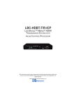
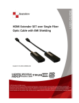
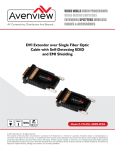
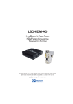
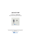
LBO-USB
LINK BRIDGETM FIBER OPTIC
USB HUB EXTENSION SYSTEMS
BCI reserves the right to make changes to the products described herein without
prior notice or consent. No liability is assumed as a result of their use or
application. All rights reserved.
©2013 Broadata Communications, Inc.
LBO-USB User’s Manual
Link BridgeTM Fiber Optic USB Hub Extension Systems
SAFETY INSTRUCTIONS AND COMPLIANCE DECLARATIONS
PLEASE OBSERVE THE FOLLOWING SAFETY PRECAUTIONS AS OUR
PRODUCTS CONTAIN
CLASS I LASER PRODUCTS
WARNING
This product is a CLASS I LASER PRODUCT only when the units are connected
with a fiber optical cable. Do not disconnect the fiber optic connector while
the unit is powered up. Exposure to laser radiation is possible when the
laser fiber optic connector is disconnected while the unit is powered up. It
should be noted that when the fiber is disconnected, the product will have
CLASS IM INVISIBLE LASER RADIATION.
Although the fiber optic connectors in this product emit only Class 1 energy
that is below the levels considered to be hazardous, one should never stare
directly into a fiber optic connector or an unconnected fiber end unless one
can be certain that no exposure to laser energy could occur.
CAUTION
Only service personnel are intended to access the interior of the units. It
should be cautioned that CLASS 3 INVISIBLE LASER RADIATION WHEN
OPEN, AVOID EXPOSURE TO THE BEAM. The use of controls, making
adjustments, or performing operations other than those specified may result
in hazardous radiation exposure. This product has operating wavelengths
at 778nm, 800nm with average -0.5dB to 0dBm optical power per wavelength,
825nm, 911nm, and 980nm. The laser is operated in pulse mode within 1
KHz frequency and ¼ duty cycle.
The following label or equivalent is located on the surface of laser products.
This label indicates that the product is classified as a CLASS 1 LASER
PRODUCT.
SURGE PROTECTION DEVICE RECOMMENDED
This product contains sensitive electrical components that may be damaged
by electrical spikes, surges, electric shock, lightning strikes, etc. Use of
surge protection systems is highly recommended in order to protect and
extend the life of your equipment.
Broadata Technical Support, [email protected]
3
LBO-USB User’s Manual
Link BridgeTM Fiber Optic USB Hub Extension Systems
TABLE OF CONTENTS
1.0 PRODUCT DESCRIPTION .............................................5
2.0 SETUP .............................................................................. 7
2.1 MOUNTING ......................................................................7
2.2 CABLING AND CONNECTORS ..................................... 7
2.3 ELECTRICAL CABLE CONNECTION ...........................8
2.3.1 DATA CHANNEL CONNECTION .................................8
2.3.2 OPTICAL FIBER CONNECTION .................................9
2.4 DC POWER CONNECTION .......................................... 10
3.0 OPERATION ................................................................... 11
4.0 MAINTENANCE AND TROUBLESHOOTING.............. 12
4.1 MAINTENANCE ............................................................. 12
4.2 TROUBLESHOOTING .................................................. 12
5.0 SPECIFICATIONS .......................................................... 14
6.0 SERVICE PROCEDURE ............................................... 15
6.1 REPLACEMENT POLICY ............................................. 15
6.2 RETURN AND REPAIR SERVICE ................................. 15
7.0 LIMITED WARRANTY .................................................... 16
4
Broadata Technical Support, (800) 214-0222
LBO-USB User’s Manual
Link BridgeTM Fiber Optic USB Hub Extension Systems
1.0 PRODUCT DESCRIPTION
The Link Bridge LBO-USB Series is a high performance, yet affordable,
Fiber Optic USB Hub Extension System that is designed to carry 4-port
USB hub signal, over long distances through one pair of multimode or
singlemode fibers. Many versions of optical transmitter and receiver
combinations are available to address different distance requirements.
No user adjustments are required in the LBO-USB system due to the
use of advanced digital fiber optic transmission technology. This allows
for a quick and easy setup, offering trouble-free operation for many years
to come.
The LBO-USB is available in two packaging options: a rugged, standalone
unit housed in a compact case, or a plug-in card for our card cage system.
Panel connectors are provided for the USB type-A/B and SC-type fiber
connectors. The LBO-USB can be easily monitored by LED indicators
for power, optical link, and data activity. The standalone units are powered
by +12VDC.
Broadata Technical Support, [email protected]
5
PWR
OPT LINK
USB LINK
LBO-USB User’s Manual
Link BridgeTM Fiber Optic USB Hub Extension Systems
USB
HOST
PWR
OPT LINK
USB LINK
LBO-USB-H
LBO-USB-D
USB
2
1
USB
2
1
LINK PORT
+12VDC
1.5 AMP
TX
RX
Figure 1-1
LBO-USB Front/Rear Panels
6
Broadata Technical Support, (800) 214-0222
LBO-USB User’s Manual
Link BridgeTM Fiber Optic USB Hub Extension Systems
2.0 SETUP
The Link Bridge LBO-USB Series units are used in pairs. One
LBO-USB-H (Host) transceiver unit is located at the near end and
connected through two optical fibers to LBO-USB-D (Device) transceiver
located at the far end of the link. Each unit provides an electrical interface
connector for the USB data signals. Figure 2-1 depicts a typical
installation.
Figure 2-1
LBO-USB Setup
2.1 Mounting
Before installing the units into your housing, make sure there is
enough space to pull and connect both the electrical and optical
cables without stressing them beyond the manufacturer’s
limitations (also known as the bend radius minimum). Rack
mount kits are available for half-size versions only, with internal
power supplies.
2.2 Cabling and Connectors
In order to setup the LBO-USB properly, make sure to observe
the following instructions when installing the proper cables. The
LBO-USB requires two parts to the cabling setup: the electrical
and the optical.
Broadata Technical Support, [email protected]
7
LBO-USB User’s Manual
Link BridgeTM Fiber Optic USB Hub Extension Systems
2.3 Electrical Cable Connection
The only available cable connections on the electrical side is
for the USB connections.
2.3.1 Data Channel Connection
Use the following steps to connect to your data equipment.
1. Before connecting your user supplied equipment, wire
up the proper cabling to connect from the LBO-USB to
the end-user’s USB equipment.
2. At the Host end (LBO-USB-H), connect one end of
computer USB data cable to the user’s Host USB
equipment (e.g., PC’s USB port) and the other end to
the LBO-USB’s USB port.
3. At the Device end (LBO-USB-D), connect up to 4 USB
devices (e.g., web cam, printers, etc.) to the
corresponding ports in the LBO-USB-D unit.
8
Broadata Technical Support, (800) 214-0222
LBO-USB User’s Manual
Link BridgeTM Fiber Optic USB Hub Extension Systems
2.3.2 Optical Fiber Connection
Most cable manufacturers identify individual fibers in the
fiber cable. Select an appropriate terminated fiber. Each
unit’s optical ports in the system are specified for use with
Multimode (62.5/125 micron) fiber, or Singlemode (9/125
micron) fiber. Follow the ensuing instructions on installing
and connecting the fiber optic links:
1. Ensure the power is off before proceeding with the fiber
optic cable installation.
2. Prior to connecting the fiber optic cables, remove and
save the dust caps from the optical port of both the
LBO-USB units. Clean the fiber optic connector and
use a lint-free cloth dampened with alcohol to thoroughly
wipe the side and end of the ferrule.
3. Cross-connect the fibers from one unit to the other,
connecting the near end LBO-USB unit’s optical TX
port to the far end LBO-USB unit’s optical RX port, as
illustrated in Figure 2-1. Observe the type of connector
you have and connect the optical connector.
PWR
OPT LINK
USB LINK
To PC/USB Host
USB
HOST
To USB
peripheral
devices
LBO-USB-H
LINK PORT
+12VDC
1.5 AMP
PWR
OPT LINK
USB LINK
TX
LBO-USB-D
USB
2
1
USB
RX
2
1
LINK PORT
+12VDC
1.5 AMP
TX
RX
Figure 2-1
Fiber Optic Connection
Broadata Technical Support, [email protected]
9
LBO-USB User’s Manual
Link BridgeTM Fiber Optic USB Hub Extension Systems
2.4 DC Power Connection
Congratulations! You are now ready to power up the BCI LBO-USB and
set up your network connection. In order to make sure that you have a
proper installation, please observe the following:
1. Your AC jack has power.
2. The 12VDC power supply is working.
3. Your electrical system has proper grounding (this ensures that
your power supply does not suffer from voltage variations).
4. Power Surge Protection. This is optional, but highly
recommended. A UPS system provides voltage regularity as
well as prevents spikes from occurring, thus protecting your
LBO-USB from sensitive voltage conditions.
The LBO-USB derives power from an external 12VDC power supply.
This power supply is a wall-mounted AC/DC adapter, 100-240 VAC,
50-60 Hz, @1.5 A. This power supply comes standard for the LBO-USB
Series unless otherwise specified.
To provide power to the LBO-USB, simply connect the power supply,
already provided with the units, and connect it to the wall jack. (You will
find one power supply per unit). Once the power supply has been
connected to the wall jack, connect the 12VDC to the unit and the unit
should power up immediately.
If you have any problems or concerns, regarding the installation, make
sure that you have taken the proper steps to ensure a proper power
connection. Otherwise, feel free to contact us for any questions you
may have.
10
Broadata Technical Support, (800) 214-0222
LBO-USB User’s Manual
Link BridgeTM Fiber Optic USB Hub Extension Systems
3.0 OPERATION
After the installation procedure is completed, the units are ready for
operation. To operate the BCI LBO-USB units, simply apply power as
indicated in the previous step. Note that the front panel link status
indicator will be activated, as shown in Table 3-1.
Broadata Technical Support, [email protected]
11