1
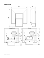
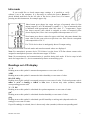
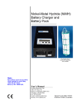
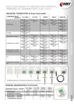
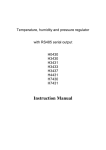
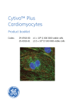
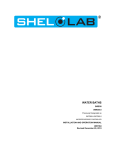
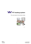
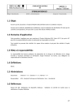
Programmable indoor transmitter of temperature T0118 Programmable indoor transmitter of atmospheric pressure T2118 Programmable indoor transmitter of temperature, relative humidity and other derived humidity values T3118 with current output 4 to 20 mA Instruction Manual Instruction Manual Device type T0118 T2118 T3118 Temperature Humidity Computed value Pressure - Output name I1 I1 I1, I2 Devices are designed for indoor applications. By device type (see previous table) they can measure ambient temperature at °C or °F, relative humidity of air without aggressive ingredients or atmospheric pressure at hPa, PSI, inHg, mBar, oz/in2, mmHg, inH2O or kPa. Unit choice is provided by User’s software – see later. It is possible to choice one of the following computed value (for T3118 device only): dew point temperature, absolute humidity, specific humidity, mixing ratio or specific enthalpy. Device T2118 supports pressure correction for altitude setting (offset). All device setting is performed by means of the PC connected via the optional SP003 communication cable (not included in delivery) and User’s software Tsensor. Program Tsensor for device setting is available to download free at www.cometsystem.cz. It supports make the adjustment of the device too. This procedure is described at file „Calibration manual.pdf“ which is installed commonly with the software. Program enables to set own device output range, unit selection and make an adjustment process. For T3118 device allows to assign required measured value to one of the two device outputs, it means assign temperature, relative humidity or computed value to output I1 or I2 and set its range. It is also possible to assign both outputs to the same value (with the same range), if two evaluation devices are necessary to connect. Device is connected to circuitry by means of one or two galvanic isolated loops. Each loop has two-wire connection and each loop requires power from evaluation device. It is always necessary to connect current loop I1 for proper device function (from loop I1 part of the device is powered). If current loop I1 is opened or disconnected, then loop I2 and LCD will not work. Measured and computed values are optionally shown on dual line LCD display. If there are two values displayed at one LCD line, they are periodically switched between both readings with period of 4 seconds. Display can be switched OFF totally too. Temperature, relative humidity eventually pressure sensors are non-removable device parts. Please read instruction manual before the first device connection. Device setting from the manufacturer If special setting was not required in the order device is set from the manufacturer to the following parameters: T0118: output I1: temperature, range from 4 to 20 mA corresponds with -10 to +50 °C T2118: output I1: atmospheric pressure, range from 4 to 20 mA corresponds with 800 to 1100 hPa correction for altitude 0 hPa (absolute pressure) T3118:output I1: relative humidity, range from 4 to 20 mA corresponds with 0 to 100 % RH output I2: temperature, range from 4 to 20 mA corresponds with -10 to +50 °C LCD display: switched ON Change of this manufacturer device setting is possible with the PC connected via the optional SP003 communication cable and User’s software Tsensor as described at the end of this document. 2 IE-SNC-Tx118-02 Dimensions T0118, T2118 IE-SNC-Tx118-02 T3118 3 Device installation Devices are designed for indoor applications. It is recommended to mount them on universal wiring box (common installation box KU68) with using two enclosed mounting screws. For correct function there is necessary to find proper device place. It shouldn’t be placed at places where it can be affected by sunshine, near radiators, heating elements and other heat sources, air handlers, windows, doors, into racks and shelves and similar places. For buildings with less thermal insulation there is not suitable to place them on external walls of building. If there are communication conductors placed into conduit, there is strongly recommended make it caulk, to restrict air flow around device. It is recommended to use shielded copper cable (e.g. SYKFY), maximal length 1200m. The cable must be located at indoor rooms (device is not protected for outdoor use). The cable should not be led in parallel along power cabling. Safety distance is up to 0.5 m otherwise undesirable induction of interference signals can appear. Electrical system (wiring) may do only worker with required qualification by rules in operation. Setting of pressure correction for altitude For device T2118 only! If there is necessary to read value of atmospheric pressure corrected with respect to altitude, it is possible to set corresponding pressure offset for this altitude. It is possible to do it with Users software. This value is then automatically added to measured pressure value. The resultant value of pressure with added correction for altitude must be between 300 hPa and 1350 hPa (from 4.351 PSI to 19.580 PSI). Outside this range device sends value of Error 2! Device mounting Firstly mount back part of device onto wiring box with two holding screws. Connect cables to terminals with respecting the signal polarity (see figure). Terminals are self-clamping and can be opened by a suitable screwdriver. For the opening, insert the screwdriver to upper terminal hole and lever by him. Then insert front part of device firstly at bottom into hinge and then press both parts together – see figure1 Figure1: Device mounting 4 IE-SNC-Tx118-02 IE-SNC-Tx118-02 5 Device demounting If there is necessary demount the device, insert flat bladed screwdriver max. 3.5 mm wide from top side into middle device’s air hole. There is fastening member placed, insert screwdriver beyond the fastening member about 2 cm deep – number at the picture. Then slightly move screwdriver in arrow direction as shown at the picture. It unlock fastening member and the device is partially opened. Remove the screwdriver and take front part of device at top, see number at the picture. Pull front part with pendulum motion, remove front cover, numbers and at the picture. If there is necessary remove back part of device, please disconnect cables and unscrew two holding screws. Figure2: Device demounting Typical application wiring, connection of terminals Calculation of minimum power voltage Uss for proper operation: Uss min> Uo min + Imax * Rz, where: Uo min= 9 V Imax... approximately 20 mA Rz... sensing resistor (shunt) For device T3118: Both current loops (I1 and I2) are connected analogically, current loop I1 must be always connected. 6 IE-SNC-Tx118-02 Info mode If you would like to check output range settings, it is possible to verify without a use of the computer. It is necessary to connect the power. Button is placed behind small hole on the left side of the device (front view). For button pressing use thin instrument, for example paper clip. Short button press shows low range and type of measured value for first output (output I1, at LCD indicated by symbol „1“). Type of measured value is indicated with appropriated value unit. (here °C = temperature). Upper line shows current value which is assigned to value of measured value (lower display line). Here 4 mA corresponds with temperature of -10 °C. Next button press shows values for upper scale limit. (the same channel, the same value) by the same rules as at previous case. Here 20 mA corresponds with temperature of 50 °C. For T3118 device there is analogously shown I2 output setting. Next press of button exits info mode and actual measured values are displayed. Note: For atmospheric pressure device T2118 there is at the lower LCD line shown current value assigned to atmospheric pressure value shown at upper LCD line. Note: No measurement and communication is possible during info mode. If device stays in info mode for longer than 15 s, device automatically returns to measuring cycle. Readings on LCD display °C, °F Reading next to this symbol is measured temperature or error state of value. %RH Reading next to this symbol is measured relative humidity or error state of value. hPa, PSI, inHg, Reading next to this symbol is measured pressure or error state of value. If selected pressure unit is mBar or oz/in2 or mmHg or inH2O or kPa, there is shown only value (number) without corresponding pressure unit! °C / °F DP Reading next to this symbol is calculated dew point temperature or error state of value. g/m3 Reading next to this symbol is calculated absolute humidity or error state of value. g/kg Reading next to this symbol is calculated specific humidity or mixing ratio (depends on device setting) or error state of value. If specific enthalpy is selected, there is shown only value (number) without corresponding unit! IE-SNC-Tx118-02 7 Technical parameters of the device: Accuracy data shown are for value displayed on LCD display. For value on analog output is valid too, if selected output range is set inside measuring range. Analog outputs: T0118, T2118: one output channel I1, range from 4 to 20 mA T3118: two galvanic isolated outputs I1 and I2, range 4 to 20 mA Current output in case of error: approximately <3.8 mA or >24 mA Power: 9 to 30 V DC, maximum ripple 0.5 % Measuring parameters: Ambient temperature – T0118, T3118: Measuring range: -10 to +50 °C Display resolution: 0.1 °C Accuracy: ± 0.5 °C Response time: air flow approximately 0.3 m/s t90 < 12 min No air flow t90 < 25 min Atmospheric pressure – T2118 only: - accuracy of value shown on LCD display: Unit Range hPa, mBar 600 1100 PSI 8.70 15.95 mmHg 450.0 825.1 inHg 17.72 32.48 inH2O 240.9 441.6 oz/in2 139.2 255.3 kPa 60.00 110.00 accuracy ±1.3 ±0.02 ±1.0 ±0.04 ±0.5 ±0.3 ±0.13 T=23 °C ±1.5 ±0.02 ±1.1 ±0.04 ±0.6 ±0.3 ±0.15 0≤T≤40°C ±2.0 ±0.03 ±1.5 ±0.06 ±0.8 ±0.5 ±0.20 Else Output accuracy: ±(accuracy of value shown on LCD display + 0.06% FS)hPa Response time 1: t90 <44 s Relative humidity - T3118 only (reading is temperature compensated at entire temperature range): Measuring range: 5 to 95 % RH (see Device installation) Display resolution: 0.1 % RH Accuracy: ± 2.5 %RH for range from 5 to 60 %RH, ± 3 %RH for range from 60 to 95 %RH, at 23 °C Response time: t90 < 30 s (air flow approximately 1 m/s, relative humidity step 65 %RH, constant temperature) 1 There is possible to change response time. For more details see file “Description of calibration and adjustment procedure.pdf”, which is installed together with Users software. 8 IE-SNC-Tx118-02 The value computed from ambient temperature and relative humidity - T3118 only: You can choice one of the next value. Display resolution: 0.1 °C Dew point temperature Accuracy: ±1.6 °C at ambient temperature T < 25 °C and RH > 30 % Range: -60 to +80 °C Absolute humidity Accuracy: ±3g/m3 at ambient temperature T < 40 °C and RH < 95 % Range: 0 to 400 g/m3 Specific humidity 2 Accuracy: ±2g/kg at ambient temperature T < 35 °C and RH < 95 % Range: 0 to 550 g/kg Mixing ratio 2 Accuracy: ±2.2g/kg at ambient temperature T < 35 °C and RH < 95 % Range: 0 to 995 g/kg Specific enthalpy 2 Accuracy: ± 3.5kJ/kg at ambient temperature T < 25 °C and RH < 95 % Range: 0 to 995 kJ/kg Recommended calibration interval: T0118 2 years T2118, T3118 1 year Measuring interval and LCD display refresh: 0.5 s, T2118 2 s Communication with computer: via USB port by means of USB communication cable SP003 Protection: IP20 Operating conditions: Operating temperature range: -10 to +50 °C Operating humidity range: 0 to 100 %RH (without condensation) Outer characteristics in accordance with EN33-2000-3 normal environment with the specifications: AE1, AN1, BE1 Electromagnetic compatibility: complies EN 61326-1 Storing conditions: temperature -30 to +80 °C, humidity 0 to 100 %RH without condensation Not allowed manipulations: It is not allowed to operate the device under other than specified conditions in technical parameters. Devices are not designed for locations with chemically aggressive environment. Temperature and humidity sensors must not be exposed to direct contact to water or other liquids. Do not use the device in an explosive environment. Dimensions: 106 x 88 x 33 (h x l x d) Weight: approximately 150 g Material of the case: ABS 2 This value depends on the atmospheric pressure. For computing there is used constant value stored inside the device memory. Default value preset by manufacturer is 1013hPa and can be changed by user’s software. IE-SNC-Tx118-02 9 Procedure of modification of device adjustment: device adjustment is performed by means of the optional SP003 communication cable, connected to USB port of the PC. It is necessary to have installed configuration program Tsensor on the PC, It is free to download at www.cometsystem.cz. During installation please take care about installation of driver for USB communication cable Demount the device (see chapter “Device demounting”) Connect SP003 communication cable to the device and PC. Installed USB driver detect connected cable and create virtual COM port inside the PC. Display must light up, or at least must light up all symbols for one second (if LCD was switched OFF by program before). Run installed Tsensor program and select corresponding communication COM port (as described above) Now make new device setting throw Tsensor program When new setting is saved and finished, disconnect the cable from the device and mount the device. Error States of the device Device continuously checks its state during operation. In case error is found LCD displays corresponding error code: Error 0 First line displays „Err0“. Check sum error of stored setting inside device’s memory. Output value is < 3.8 mA. This error appears if incorrect writing procedure to device’s memory occurred or if damage of calibration data appeared. At this state device does not measure and calculate values. It is a serious error, contact distributor of the device to fix. Error 1 Measured or calculated value except in pressure is over upper limit of allowed full scale range. There is a reading „Err1“ on LCD display. Output value is about 24.5 mA This state appears in case of: Measured temperature is higher than approximately 600°C (i.e. high non-measurable resistance of temperature sensor, probably opened circuit). Relative humidity is higher than 100%, i.e. damaged humidity sensor, or humidity calculation of humidity is not possible (due to error during temperature measurement) Computed value – calculation of the value is not possible (error during measurement of temperature or relative humidity or value is over range) Error 2 There is a reading „Err2“ on LCD display. Measured or calculated value is below lower limit of allowed full scale range or atmospheric pressure error occurred. Output value is about 3.8 mA. This state appears in case of: Measured temperature is lower than approximately -210°C (i.e. low resistance of temperature sensor, probably short circuit). 10 IE-SNC-Tx118-02 Relative humidity is lower than 0%, i.e. damaged sensor for measurement of relative humidity, or calculation of humidity is not possible (due to error during temperature measurement) Computed value – calculation of computed value is not possible (error during measurement of temperature or relative humidity) Measured pressure value with added correction for altitude is outside of range from 300 hPa to 1350 hPa (from 4.351 PSI to 19.580 PSI) or the pressure sensor is damaged. Please check setting of pressure correction for altitude with User’s software. Error 3 There is a reading „Err3“ on LCD display upper line. Error of internal A/D converter appeared (converter does not respond, probably damage of A/D converter). This error does NOT affect pressure measurement. Rest values are NOT measured. Output value is about 3.8 mA. It is a serious error, contact distributor of the device. Error 4 There is a reading „Err4“ on LCD display. It is internal device error during pressure sensor initialization. Under this condition device does NOT measure atmospheric pressure Output value is about 3.8 mA. Pressure sensor is probably damaged. It is a serious error, contact distributor of the device. End of operation Device itself (after its life) is necessary to liquidate ecologically! Technical support and service Technical support and service is provided by distributor. For contact see warranty certificate IE-SNC-Tx118-02 11